EP2285662B1 - A chock insert for a maritime craft - Google Patents
A chock insert for a maritime craft Download PDFInfo
- Publication number
- EP2285662B1 EP2285662B1 EP09732880.1A EP09732880A EP2285662B1 EP 2285662 B1 EP2285662 B1 EP 2285662B1 EP 09732880 A EP09732880 A EP 09732880A EP 2285662 B1 EP2285662 B1 EP 2285662B1
- Authority
- EP
- European Patent Office
- Prior art keywords
- chock
- insert
- rope
- passageway
- running surface
- Prior art date
- Legal status (The legal status is an assumption and is not a legal conclusion. Google has not performed a legal analysis and makes no representation as to the accuracy of the status listed.)
- Active
Links
Images




Classifications
-
- B—PERFORMING OPERATIONS; TRANSPORTING
- B63—SHIPS OR OTHER WATERBORNE VESSELS; RELATED EQUIPMENT
- B63B—SHIPS OR OTHER WATERBORNE VESSELS; EQUIPMENT FOR SHIPPING
- B63B21/00—Tying-up; Shifting, towing, or pushing equipment; Anchoring
- B63B21/04—Fastening or guiding equipment for chains, ropes, hawsers, or the like
- B63B21/10—Fairleads
-
- B—PERFORMING OPERATIONS; TRANSPORTING
- B63—SHIPS OR OTHER WATERBORNE VESSELS; RELATED EQUIPMENT
- B63B—SHIPS OR OTHER WATERBORNE VESSELS; EQUIPMENT FOR SHIPPING
- B63B21/00—Tying-up; Shifting, towing, or pushing equipment; Anchoring
- B63B21/04—Fastening or guiding equipment for chains, ropes, hawsers, or the like
-
- B—PERFORMING OPERATIONS; TRANSPORTING
- B63—SHIPS OR OTHER WATERBORNE VESSELS; RELATED EQUIPMENT
- B63B—SHIPS OR OTHER WATERBORNE VESSELS; EQUIPMENT FOR SHIPPING
- B63B21/00—Tying-up; Shifting, towing, or pushing equipment; Anchoring
- B63B21/04—Fastening or guiding equipment for chains, ropes, hawsers, or the like
- B63B21/14—Hawse-holes; Hawse-pipes; Hawse-hole closures
Definitions
- the invention relates to a chock insert for a maritime craft, particularly a ship but also for use in rigs and floating platforms.
- Chocks on ships, rigs, floating platforms and other maritime craft or installations generally comprise a flared aperture through which mooring ropes can pass.
- the flared nature of the chock is intended to prevent the mooring rope from passing over a small radius which would increase the level of wear on the rope.
- the mooring ropes are held under tension against the surface of the chock and the chock and rope running through it move relative to each other due to the movement of the craft, for example due to swell, the tides, wind and other phenomena.
- the chocks on vessels are generally made of sand cast steel. Whilst the sand cast steel surface does not present a wear problem for steel wire rope, the surface is rough enough to accelerate wear in fibre ropes. Chocks are also prone to rust which increases the abrasive qualities of the chock when the fibre rope is passing over it.
- FR2371371 describes a fairlead having a sleeve through which a rope may extend, one end of the sleeve being rigidly connected at an inboard end of the fairlead and the other end of the sleeve being free to move relative to the outboard end of the fairlead.
- DE20014131U1 describes a fairlead that may be mounted in a hole of a ship's wall to allow the passage of a rope there through.
- the fibre rope runs over a plastics material surface which is less abrasive.
- the outer surface of the body of the chock insert is preferably arranged to conform to part of the inner surface of the chock. Most preferably, the outer surface of the body of the insert conforms substantially to the entire inner surface of the chock.
- the body is formed in two parts.
- the two parts of the body are preferably secured together compressively, for example by screw threaded fastener means, such as a series of nuts and bolts. Any gap that exists between the two parts of the body may be filled with a filler material.
- the two parts of the body comprise an inner part and an outer part, the inner part being arranged to conform to the onboard side of the chock and the outer part being arranged to conform to the outboard side of the chock.
- the passageway may be bounded on all sides by the body of the chock insert.
- the passageway may be circular, elliptical or obround.
- the rope running surface preferably extends around the entrance to the passageway, the exit to the passageway or both sides of the passageway.
- the rope running surface may comprise the entire surface of the passageway.
- the plastics material of the rope running surface may comprise a removable plastics insert.
- the plastics material may be one selected from the group of polyamide, polyester, epoxy or polyurethane.
- the plastics material may comprise a composite material comprising a plastics material matrix with a filler of different materials.
- the fillers may be provided so as to alter the performance of the rope running surface.
- the fillers may reduce the surface friction of the rope running surface.
- the fillers may improve the wear properties of the rope running surface.
- the fillers may be selected from the group of PTFE, FEP or graphite particles.
- the plastics material matrix can have fibrous or other strengthening materials added to it.
- the fibrous materials may be glass, aramid or carbon fibre or other suitable fibre reinforcing material.
- the body may be made by casting. Where the rope running surface comprises a separate plastics insert, the insert should be made by casting. Although it is less preferred, the body or insert could also be made by rotomoulding or injection moulding the plastics material.
- a chock insert 10 comprises a first and second trumpet-shaped body parts 12, 14.
- the body parts 12, 14 butt together at their respective narrow ends 12a, 14a and flare outwardly to flared ends 12b, 14b.
- the parts 12, 14 are secured together by means of multiple nut and bolt fastener assemblies 16 which extend through apertures 18 and bores 20 formed respectively in each body part 14, 12.
- the body parts 12, 14 are made of plastics material, for example a polyamide, a polyester, epoxy or a polyurethane.
- the inner surfaces of the body parts 12, 14 define a rope running surface over which mooring rope can run.
- the plastics material surface is less abrasive to synthetic fibre rope than the surface of a chock.
- Fig.2 one side of the chock insert 10 is shown.
- the body part 14 in Fig.2 is the craft side part of the chock insert. In other words, in use, that part is arranged to face towards the craft when installed on the chock.
- the body part 14 comprises an obround narrow end 14a and an obround wide end 14b.
- a parabolically flaring wall 14c extends between the narrow end 14a and the wide end 14b.
- Six fastener receiving apertures 18 are formed equally angularly spaced around the inside surface of the body part 14. The apertures 18 extend through the body part 14 and emerge on the end face of the body part 14 at the narrow end 14a. Only four apertures are shown in Fig.2 .
- Bolts 16a of the nut and bolt fastener assembly 16 are arranged in the apertures 18.
- the chock body part 12 shown is the quay-side part of the chock insert.
- the part 12 is the part that, when arranged on the ship or other maritime craft, faces towards the quay.
- the part 12 comprises an obround narrow end 12a, an obround wide end 12b and a parabolically flared wall 12c extending between the ends 12a, 12b.
- a series of bores 20 are formed in the end face of the narrow end 12a of the body part 12.
- the bores extend through the body towards the wide end 12b and they receive a nut of the nut and bolt fastener arrangement 16.
- Access apertures 22 extend from the outer surface of the body part 12 inwardly towards the bores 20 to enable either insertion or manipulation of a nut of the nut and bolt fastener arrangement 16.
- Fig.4 the chock insert 10 is shown, schematically, assembled upon a chock of a ship or other maritime craft.
- a ship (not shown) has a ship wall 24 in which a chock 26 is mounted.
- the chock 26 is supported by chock mounting webs 28 which may be bolted or welded to the ship wall 24.
- the chock 26 defines an aperture generally indicated at 30 through the ship wall 24, through which a rope R can run.
- the running surface of the chock 26 is rough and tends to wear synthetic fibre rope.
- the chock insert 10 is arranged within the chock 26 so as to cover the surface of the chock 26.
- the chock insert 10 is secured on the chock by means of the nut and bolt arrangements 16 as shown in Figs. 1-3 .
- the rope R runs over the inner surface of the chock insert 10 rather than the surface of the chock 26.
- the inner surface of the chock 10 is considerably less wearing on synthetic fibre rope R than the surface of the chock.
- the quay-side part 12 is larger than the craft-side part 14.
- they may be identical in size or the craft-side part may be larger than the quay-side part.
- various shapes of chock inserts are possible.
- the parts 12, 14 could be conical in shape.
- the aperture defined by the chock insert 10 could vary in shape from circular, through elliptical to obround. It is likely that the aperture will always have a rounded profile and the inner surface of the insert will flare convexly so as to maximise the radii over which the rope must pass.
- a test rig 34 comprises opposite drive mechanisms 36, 38 which are spaced apart from each other and which drive away from each other.
- a rope R is secured between the drive mechanisms 36, 38 and passes over a first roller 40, through a chock 42 and over a second roller 44.
- the drive mechanisms 36, 38 are intended to pull the rope back and forth as illustrated by the arrow in Fig.5 through the chock 42.
- Identical ropes were tested on an unfinished chock (A), on a smoothed chock (B) and then on a chock insert (C) in accordance with the invention.
- An alternative chock insert comprises a framework of a first material, for example steel, with a plastics material insert received in the framework to define the rope running surface.
Landscapes
- Chemical & Material Sciences (AREA)
- Engineering & Computer Science (AREA)
- Combustion & Propulsion (AREA)
- Mechanical Engineering (AREA)
- Ocean & Marine Engineering (AREA)
- Ropes Or Cables (AREA)
- Laminated Bodies (AREA)
- Revetment (AREA)
- Body Structure For Vehicles (AREA)
- Laying Of Electric Cables Or Lines Outside (AREA)
Description
- The invention relates to a chock insert for a maritime craft, particularly a ship but also for use in rigs and floating platforms.
- Chocks on ships, rigs, floating platforms and other maritime craft or installations generally comprise a flared aperture through which mooring ropes can pass. The flared nature of the chock is intended to prevent the mooring rope from passing over a small radius which would increase the level of wear on the rope. The mooring ropes are held under tension against the surface of the chock and the chock and rope running through it move relative to each other due to the movement of the craft, for example due to swell, the tides, wind and other phenomena.
- Mooring ropes for large vessels such as tankers, gas carriers and container ships have typically been made from steel wire. However, these ropes are heavy which makes them difficult and time consuming to handle, placing an additional burden on crew and increasing time at berth. Also, as the wire ropes become worn individual wires break away and they can cut the hands of rope handling personnel. Also, in the salt water environment steel ropes can be subject to corrosion. Accordingly, synthetic fibre ropes have been offered as an alternative to steel. Generally these synthetic fibre ropes are made from a high modulus polyethylene fibre, aramid fibre or liquid crystal polyester fibre, all of which combine high strength with good resistance to stretch and make their performance largely equivalent to steel wire rope. The ropes are lighter and easier to handle. They tend not to present sharp fibres as they wear. Also, steel ropes are prone to sparking as they drag along the deck and that risk, which is significant when it occurs on a tanker or gas carrier, is eliminated with the synthetic fibre rope.
- One issue with the synthetic fibre ropes in relation to steel ropes is that they have a relatively poor wear resistance. The chocks on vessels are generally made of sand cast steel. Whilst the sand cast steel surface does not present a wear problem for steel wire rope, the surface is rough enough to accelerate wear in fibre ropes. Chocks are also prone to rust which increases the abrasive qualities of the chock when the fibre rope is passing over it.
-
FR2371371 DE20014131U1 describes a fairlead that may be mounted in a hole of a ship's wall to allow the passage of a rope there through. - It is an object of the invention to provide an improved chock insert for a maritime craft.
- According to the invention there is provided a chock insert for a maritime craft as set out in
claim 1 appended hereto. - In that way, the fibre rope runs over a plastics material surface which is less abrasive.
- The outer surface of the body of the chock insert is preferably arranged to conform to part of the inner surface of the chock. Most preferably, the outer surface of the body of the insert conforms substantially to the entire inner surface of the chock.
- The body is formed in two parts. The two parts of the body are preferably secured together compressively, for example by screw threaded fastener means, such as a series of nuts and bolts. Any gap that exists between the two parts of the body may be filled with a filler material. The two parts of the body comprise an inner part and an outer part, the inner part being arranged to conform to the onboard side of the chock and the outer part being arranged to conform to the outboard side of the chock.
- The passageway may be bounded on all sides by the body of the chock insert. The passageway may be circular, elliptical or obround.
- The rope running surface preferably extends around the entrance to the passageway, the exit to the passageway or both sides of the passageway. The rope running surface may comprise the entire surface of the passageway. The plastics material of the rope running surface may comprise a removable plastics insert.
- The plastics material may be one selected from the group of polyamide, polyester, epoxy or polyurethane. The plastics material may comprise a composite material comprising a plastics material matrix with a filler of different materials. The fillers may be provided so as to alter the performance of the rope running surface. The fillers may reduce the surface friction of the rope running surface. The fillers may improve the wear properties of the rope running surface. The fillers may be selected from the group of PTFE, FEP or graphite particles. Alternatively or in addition to the fillers, the plastics material matrix can have fibrous or other strengthening materials added to it. The fibrous materials may be glass, aramid or carbon fibre or other suitable fibre reinforcing material.
- The body may be made by casting. Where the rope running surface comprises a separate plastics insert, the insert should be made by casting. Although it is less preferred, the body or insert could also be made by rotomoulding or injection moulding the plastics material.
- An embodiment of the invention will now be described in detail by way of example and with reference to the accompanying drawings, in which:
-
Fig.1 is a perspective view of a chock insert in accordance with the invention, -
Fig.2 is a perspective view of the first part of the chock insert, -
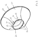
Fig.3 is a perspective view of the second part of the chock insert, -
Fig.4 is a schematic sectional view through a chock with the chock insert ofFigs. 1 to 3 installed thereon, -
Fig.5 is a schematic illustration of a chock liner test rig, -
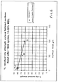
Fig.6 is a table showing results of cycle testing of synthetic fibre rope. - In
Fig.1 achock insert 10 comprises a first and second trumpet-shaped body parts body parts narrow ends ends 12b, 14b. Theparts bolt fastener assemblies 16 which extend throughapertures 18 andbores 20 formed respectively in eachbody part - The
body parts - The inner surfaces of the
body parts - In
Fig.2 , one side of thechock insert 10 is shown. - The
body part 14 inFig.2 is the craft side part of the chock insert. In other words, in use, that part is arranged to face towards the craft when installed on the chock. Thebody part 14 comprises an obroundnarrow end 14a and an obroundwide end 14b. A parabolically flaring wall 14c extends between thenarrow end 14a and thewide end 14b. Sixfastener receiving apertures 18 are formed equally angularly spaced around the inside surface of thebody part 14. Theapertures 18 extend through thebody part 14 and emerge on the end face of thebody part 14 at thenarrow end 14a. Only four apertures are shown inFig.2 .Bolts 16a of the nut andbolt fastener assembly 16 are arranged in theapertures 18. - Turning to
Fig.3 , thechock body part 12 shown is the quay-side part of the chock insert. In other words, thepart 12 is the part that, when arranged on the ship or other maritime craft, faces towards the quay. - Again, as with the
part 14, thepart 12 comprises an obroundnarrow end 12a, an obround wide end 12b and a parabolically flared wall 12c extending between theends 12a, 12b. - A series of
bores 20 are formed in the end face of thenarrow end 12a of thebody part 12. The bores extend through the body towards the wide end 12b and they receive a nut of the nut andbolt fastener arrangement 16.Access apertures 22 extend from the outer surface of thebody part 12 inwardly towards thebores 20 to enable either insertion or manipulation of a nut of the nut andbolt fastener arrangement 16. - In
Fig.4 , thechock insert 10 is shown, schematically, assembled upon a chock of a ship or other maritime craft. - In
Fig.4 , a ship (not shown) has aship wall 24 in which achock 26 is mounted. Thechock 26 is supported bychock mounting webs 28 which may be bolted or welded to theship wall 24. - The
chock 26 defines an aperture generally indicated at 30 through theship wall 24, through which a rope R can run. The running surface of thechock 26 is rough and tends to wear synthetic fibre rope. InFig.4 , thechock insert 10 is arranged within thechock 26 so as to cover the surface of thechock 26. The chock insert 10 is secured on the chock by means of the nut andbolt arrangements 16 as shown inFigs. 1-3 . As can be seen inFig.4 , the rope R runs over the inner surface of the chock insert 10 rather than the surface of thechock 26. The inner surface of thechock 10 is considerably less wearing on synthetic fibre rope R than the surface of the chock. - In the chock insert of
Figs.1-3 , the quay-side part 12 is larger than the craft-side part 14. However, they may be identical in size or the craft-side part may be larger than the quay-side part. Also, various shapes of chock inserts are possible. For example, theparts chock insert 10 could vary in shape from circular, through elliptical to obround. It is likely that the aperture will always have a rounded profile and the inner surface of the insert will flare convexly so as to maximise the radii over which the rope must pass. - The chock insert 10 in accordance with the invention was tested in a test rig as shown in
Fig.5 . InFig.5 atest rig 34 comprisesopposite drive mechanisms drive mechanisms first roller 40, through achock 42 and over asecond roller 44. Thedrive mechanisms Fig.5 through thechock 42. Identical ropes were tested on an unfinished chock (A), on a smoothed chock (B) and then on a chock insert (C) in accordance with the invention. After 1500 cycles back and forth through the chock, the rope used on the unfinished chock retained just over 60% of its residual strength. The rope that was used in the relation to the smoothed chock had around 67% of its original strength. A series of ropes tested on the chock insert retained between 78% and 85% of their residual strength after 1500 cycles. Thus it can be seen that the use of the chock insert substantially improves the fatigue life of ropes passing through the chock insert in comparison to ropes passing through both finished and unfinished chocks. - An alternative chock insert comprises a framework of a first material, for example steel, with a plastics material insert received in the framework to define the rope running surface.
Claims (11)
- A chock insert (10) for a maritime craft comprising a body arranged to be receivable within or mountable to a flared chock, in which the body is formed in two parts (12, 14), the two parts of the body comprising an inner part (14) and an outer part (12), the parts (12, 14) being secured together, the body having an outer surface and an inner surface, the inner surface defining a passageway through the body to allow passage of a rope, the inner surface providing a substantially smooth rope running surface which rope passing through the passageway can run over in direct contact therewith, the rope running surface comprising a plastics material, characterised in that the inner part (14) is trumpet-shaped to conform to the onboard side of the flared chock and the outer part (12) being trumpet-shaped to conform to the outboard side of the flared chock, and in that the inner part (14) and the outer part (12) butt together at their respective narrow ends (14a, 12a) and flare outwardly to flared ends (14b, 12b).
- A chock insert (10) according to claim 1, in which the two parts of the body (12, 14) are secured together compressively, for example by screw threaded fastener means (16), such as a series of nuts and bolts.
- A chock insert (10) according to claim 2, in which any gap that exists between the two parts (12, 14) of the body may be filled with a filler material (32).
- A chock insert (10) according to any preceding claim, in which the passageway is bounded on all sides by the body of the chock insert (10).
- A chock insert (10) according to any preceding claim, in which the passageway is circular, elliptical or obround.
- A chock insert (10) according to any preceding claim, in which the rope running surface extends around the entrance to the passageway or the exit to the passageway or both entrance and exit of the passageway.
- A chock insert (10) according to claim 6, in which the rope running surface comprises the entire surface of the passageway.
- A chock insert (10) according to any of claims 1 to 7, in which the plastics material of the rope running surface comprises a removable plastics insert.
- A chock insert (10) according to any preceding claim, in which the plastics material comprises a composite plastics material matrix with a filler of different materials.
- A chock insert (10) according to claim 9, in which the filler is provided so as to alter one or more of the performance of the rope running surface, the surface friction of the rope running surface, or the wear properties of the rope running surface.
- A chock insert (10) according to any preceding claim, in which the body is made by casting.
Priority Applications (2)
| Application Number | Priority Date | Filing Date | Title |
|---|---|---|---|
| PL09732880T PL2285662T3 (en) | 2008-04-15 | 2009-04-15 | A chock insert for a maritime craft |
| EP16167822.2A EP3081476A1 (en) | 2008-04-15 | 2009-04-15 | A chock insert for a maritime craft |
Applications Claiming Priority (2)
| Application Number | Priority Date | Filing Date | Title |
|---|---|---|---|
| GB0806822.3A GB2459270B (en) | 2008-04-15 | 2008-04-15 | A chock insert for a maritime craft |
| PCT/GB2009/000988 WO2009127832A2 (en) | 2008-04-15 | 2009-04-15 | A chock insert for a maritime craft |
Related Child Applications (2)
| Application Number | Title | Priority Date | Filing Date |
|---|---|---|---|
| EP16167822.2A Division-Into EP3081476A1 (en) | 2008-04-15 | 2009-04-15 | A chock insert for a maritime craft |
| EP16167822.2A Division EP3081476A1 (en) | 2008-04-15 | 2009-04-15 | A chock insert for a maritime craft |
Publications (3)
| Publication Number | Publication Date |
|---|---|
| EP2285662A2 EP2285662A2 (en) | 2011-02-23 |
| EP2285662B1 true EP2285662B1 (en) | 2017-12-06 |
| EP2285662B8 EP2285662B8 (en) | 2018-02-21 |
Family
ID=39433674
Family Applications (2)
| Application Number | Title | Priority Date | Filing Date |
|---|---|---|---|
| EP16167822.2A Ceased EP3081476A1 (en) | 2008-04-15 | 2009-04-15 | A chock insert for a maritime craft |
| EP09732880.1A Active EP2285662B8 (en) | 2008-04-15 | 2009-04-15 | A chock insert for a maritime craft |
Family Applications Before (1)
| Application Number | Title | Priority Date | Filing Date |
|---|---|---|---|
| EP16167822.2A Ceased EP3081476A1 (en) | 2008-04-15 | 2009-04-15 | A chock insert for a maritime craft |
Country Status (10)
| Country | Link |
|---|---|
| US (1) | US8985045B2 (en) |
| EP (2) | EP3081476A1 (en) |
| JP (1) | JP5506781B2 (en) |
| KR (1) | KR101691419B1 (en) |
| CN (1) | CN102026866B (en) |
| ES (1) | ES2661703T3 (en) |
| GB (1) | GB2459270B (en) |
| PL (1) | PL2285662T3 (en) |
| TR (1) | TR201803031T4 (en) |
| WO (1) | WO2009127832A2 (en) |
Families Citing this family (20)
| Publication number | Priority date | Publication date | Assignee | Title |
|---|---|---|---|---|
| US8333162B2 (en) * | 2010-08-12 | 2012-12-18 | Fluoron Inc. | Covered marine deck structure for rope contact |
| KR101280996B1 (en) * | 2010-10-21 | 2013-07-08 | 탱크테크 (주) | Apparatus for preventing damage of leading rope in ship |
| EP2712800B1 (en) | 2012-09-28 | 2015-08-26 | Bluewater Energy Services B.V. | A floating object provided with a permanent mooring system and a mooring line |
| GB201219812D0 (en) * | 2012-11-04 | 2012-12-19 | Foster Gavin P | Rope protector |
| US10336405B1 (en) | 2017-01-31 | 2019-07-02 | Michael Ratigan | Removable cover |
| CN109229283B (en) * | 2018-09-27 | 2019-09-20 | 中国船舶科学研究中心(中国船舶重工集团公司第七0二研究所) | Island reef exploration ROV water surface deployment recovery system and recovery method |
| KR102225827B1 (en) | 2019-04-22 | 2021-03-10 | 탱크테크(주) | Mooring rope protection device of ship |
| US11066129B2 (en) * | 2019-07-06 | 2021-07-20 | David C Brezina | Toerail grommet |
| RU197798U1 (en) * | 2019-12-18 | 2020-05-28 | Александр Петрович Платошин | VEHICLE CLOSE FOR THE VEHICLE WINCH COIL |
| FR3106778B1 (en) * | 2020-01-30 | 2025-03-07 | Groupe Dld | Side-mounted de-silting winch and method of manufacturing |
| KR102235098B1 (en) | 2020-09-02 | 2021-04-01 | 탱크테크 (주) | Mooring rope protection device of ship |
| KR102259405B1 (en) | 2020-11-17 | 2021-05-31 | 천상동 | Assembly type choke insert |
| KR102728767B1 (en) | 2022-02-24 | 2024-11-11 | 탱크테크 (주) | Mooring rope protection device of ship |
| KR102734732B1 (en) | 2023-03-10 | 2024-11-27 | 대광기업 주식회사 | Choke insert molding apparatus and molding method using the same |
| CN116573100A (en) * | 2023-05-29 | 2023-08-11 | 上海外高桥造船有限公司 | Marine rope penetrating piece |
| KR102672422B1 (en) * | 2023-08-28 | 2024-06-07 | 미르이엔지 주식회사 | Choke protection cover for ship and offshore structures |
| WO2025067009A1 (en) * | 2023-09-28 | 2025-04-03 | 启东恒昊船舶科技有限公司 | Ship fairlead sheath |
| KR102693121B1 (en) * | 2024-05-22 | 2024-08-08 | 동명산업(주) | A choke for ships |
| KR20260019985A (en) | 2024-08-02 | 2026-02-10 | 탱크테크 (주) | Separate mooring rope protection device for ships with stainless steel material |
| CN119117177A (en) * | 2024-08-22 | 2024-12-13 | 江苏申浦船舶设备有限公司 | A cable guide insert and method of use |
Citations (2)
| Publication number | Priority date | Publication date | Assignee | Title |
|---|---|---|---|---|
| US4430023A (en) * | 1981-12-17 | 1984-02-07 | Exxon Production Research Co. | Rope guiding device |
| US6916014B1 (en) * | 1999-11-13 | 2005-07-12 | Jonathan P. Thomas | Cable routing and affixment apparatus |
Family Cites Families (19)
| Publication number | Priority date | Publication date | Assignee | Title |
|---|---|---|---|---|
| US748618A (en) * | 1904-01-05 | Device for mooring and warping vessels | ||
| US316997A (en) * | 1885-05-05 | Warping-chock | ||
| FR2371371A1 (en) * | 1976-11-22 | 1978-06-16 | Emh | Flexible hawse-pipe sleeve reducing wear on ship mooring lines - is split sleeve pref. of polyolefin, polyurethane or PTFE |
| JPS5382195U (en) * | 1976-12-09 | 1978-07-07 | ||
| JPS5382195A (en) * | 1976-12-27 | 1978-07-20 | Seiko Epson Corp | Holding mechanism of crystal vibrator |
| US4173194A (en) * | 1977-12-05 | 1979-11-06 | Mclaughlin Charles S | Marine cleat for receiving a thrown line |
| JPS554278A (en) * | 1979-05-30 | 1980-01-12 | Ishikawajima Harima Heavy Ind Co Ltd | Method of manufacturing closed shock of steel plate |
| JPS56101052A (en) | 1980-01-17 | 1981-08-13 | Nippon Denso Co Ltd | Fuel vaporization promoting apparatus for internal combustion engine |
| JPS5772394U (en) * | 1980-10-21 | 1982-05-04 | ||
| KR920007732B1 (en) * | 1985-09-09 | 1992-09-16 | 모코스 에이. 에스. | Fairlead |
| US5216972A (en) * | 1991-09-06 | 1993-06-08 | Dufrene John K | Lighted cleat |
| US5280138A (en) * | 1992-03-31 | 1994-01-18 | Virginia Plastics Company, Inc. | Cable protector |
| US5307751A (en) * | 1992-07-02 | 1994-05-03 | David Shell | Device for releaseably connecting rope ends in tension |
| JP3252674B2 (en) | 1995-10-19 | 2002-02-04 | 住友電装株式会社 | Grommet |
| JP2000062683A (en) * | 1998-08-20 | 2000-02-29 | Tokuyama Corp | Anchor structure |
| NO305739B1 (en) | 1998-09-03 | 1999-07-19 | Norske Stats Oljeselskap | Device for guiding and stopping an anchor chain on a floating structure |
| DE20014131U1 (en) * | 2000-08-16 | 2001-01-25 | Niro Petersen OHG, 24939 Flensburg | Lumps |
| JP2006008169A (en) | 2004-06-24 | 2006-01-12 | Yoshida Industry Co Ltd | Container |
| JP3109434U (en) | 2004-12-16 | 2005-05-19 | 内外製綱株式会社 | Rope guard |
-
2008
- 2008-04-15 GB GB0806822.3A patent/GB2459270B/en active Active
-
2009
- 2009-04-15 EP EP16167822.2A patent/EP3081476A1/en not_active Ceased
- 2009-04-15 PL PL09732880T patent/PL2285662T3/en unknown
- 2009-04-15 TR TR2018/03031T patent/TR201803031T4/en unknown
- 2009-04-15 ES ES09732880.1T patent/ES2661703T3/en active Active
- 2009-04-15 EP EP09732880.1A patent/EP2285662B8/en active Active
- 2009-04-15 WO PCT/GB2009/000988 patent/WO2009127832A2/en not_active Ceased
- 2009-04-15 US US12/988,073 patent/US8985045B2/en active Active
- 2009-04-15 KR KR1020107025649A patent/KR101691419B1/en active Active
- 2009-04-15 JP JP2011504531A patent/JP5506781B2/en active Active
- 2009-04-15 CN CN200980117546.2A patent/CN102026866B/en active Active
Patent Citations (2)
| Publication number | Priority date | Publication date | Assignee | Title |
|---|---|---|---|---|
| US4430023A (en) * | 1981-12-17 | 1984-02-07 | Exxon Production Research Co. | Rope guiding device |
| US6916014B1 (en) * | 1999-11-13 | 2005-07-12 | Jonathan P. Thomas | Cable routing and affixment apparatus |
Also Published As
| Publication number | Publication date |
|---|---|
| CN102026866B (en) | 2015-05-20 |
| GB0806822D0 (en) | 2008-05-14 |
| JP5506781B2 (en) | 2014-05-28 |
| EP2285662B8 (en) | 2018-02-21 |
| KR101691419B1 (en) | 2017-01-09 |
| WO2009127832A3 (en) | 2010-12-16 |
| GB2459270B (en) | 2012-08-15 |
| EP3081476A1 (en) | 2016-10-19 |
| PL2285662T3 (en) | 2018-06-29 |
| CN102026866A (en) | 2011-04-20 |
| GB2459270A (en) | 2009-10-21 |
| ES2661703T3 (en) | 2018-04-03 |
| TR201803031T4 (en) | 2018-03-21 |
| US20110132248A1 (en) | 2011-06-09 |
| EP2285662A2 (en) | 2011-02-23 |
| KR20110009155A (en) | 2011-01-27 |
| KR101691419B9 (en) | 2022-12-28 |
| WO2009127832A2 (en) | 2009-10-22 |
| JP2011517642A (en) | 2011-06-16 |
| US8985045B2 (en) | 2015-03-24 |
Similar Documents
| Publication | Publication Date | Title |
|---|---|---|
| US8985045B2 (en) | Chock insert for a maritime craft | |
| US4164378A (en) | Rope fitting | |
| US9499236B1 (en) | Equipment protection sleeves | |
| US20170066507A1 (en) | Equipment protection sleeves | |
| HK1228860A1 (en) | A chock insert for a maritime craft | |
| US11364975B2 (en) | Mooring connector for connecting synthetic fibre ropes | |
| EP2712800B1 (en) | A floating object provided with a permanent mooring system and a mooring line | |
| US7455025B1 (en) | Bridal plate for mooring | |
| RU2777543C2 (en) | Mooring connecting device | |
| CN218641029U (en) | Press-fixed type cable guide hole insertion kit | |
| Black et al. | Low-friction, low-abrasion fairlead liners | |
| Volpenhein et al. | Abrasion and Twist Effects on High-Performance Synthetic Ropes for Towing Applications | |
| Sharp | Rope in the marine environment | |
| RU133090U1 (en) | SHIP BOARD | |
| HK40042786A (en) | Mooring connector for connecting synthetic fibre ropes | |
| HK40042786B (en) | Mooring connector for connecting synthetic fibre ropes | |
| Wardenier et al. | MOORING LINE SOLUTIONS FOR STATE-OF-THE-ART CONTAINER VESSELS WITH DYNEEMA® | |
| GB2562516A (en) | A Coupling Device |
Legal Events
| Date | Code | Title | Description |
|---|---|---|---|
| PUAI | Public reference made under article 153(3) epc to a published international application that has entered the european phase |
Free format text: ORIGINAL CODE: 0009012 |
|
| 17P | Request for examination filed |
Effective date: 20101112 |
|
| AK | Designated contracting states |
Kind code of ref document: A2 Designated state(s): AT BE BG CH CY CZ DE DK EE ES FI FR GB GR HR HU IE IS IT LI LT LU LV MC MK MT NL NO PL PT RO SE SI SK TR |
|
| AX | Request for extension of the european patent |
Extension state: AL BA RS |
|
| DAX | Request for extension of the european patent (deleted) | ||
| 17Q | First examination report despatched |
Effective date: 20140120 |
|
| REG | Reference to a national code |
Ref country code: DE Ref legal event code: R079 Ref document number: 602009049728 Country of ref document: DE Free format text: PREVIOUS MAIN CLASS: B63B0021140000 Ipc: B63B0021100000 |
|
| RIC1 | Information provided on ipc code assigned before grant |
Ipc: B63B 21/10 20060101AFI20161129BHEP |
|
| GRAP | Despatch of communication of intention to grant a patent |
Free format text: ORIGINAL CODE: EPIDOSNIGR1 |
|
| STAA | Information on the status of an ep patent application or granted ep patent |
Free format text: STATUS: GRANT OF PATENT IS INTENDED |
|
| INTG | Intention to grant announced |
Effective date: 20170117 |
|
| GRAJ | Information related to disapproval of communication of intention to grant by the applicant or resumption of examination proceedings by the epo deleted |
Free format text: ORIGINAL CODE: EPIDOSDIGR1 |
|
| STAA | Information on the status of an ep patent application or granted ep patent |
Free format text: STATUS: EXAMINATION IS IN PROGRESS |
|
| GRAP | Despatch of communication of intention to grant a patent |
Free format text: ORIGINAL CODE: EPIDOSNIGR1 |
|
| STAA | Information on the status of an ep patent application or granted ep patent |
Free format text: STATUS: GRANT OF PATENT IS INTENDED |
|
| INTC | Intention to grant announced (deleted) | ||
| INTG | Intention to grant announced |
Effective date: 20170627 |
|
| GRAS | Grant fee paid |
Free format text: ORIGINAL CODE: EPIDOSNIGR3 |
|
| GRAA | (expected) grant |
Free format text: ORIGINAL CODE: 0009210 |
|
| STAA | Information on the status of an ep patent application or granted ep patent |
Free format text: STATUS: THE PATENT HAS BEEN GRANTED |
|
| AK | Designated contracting states |
Kind code of ref document: B1 Designated state(s): AT BE BG CH CY CZ DE DK EE ES FI FR GB GR HR HU IE IS IT LI LT LU LV MC MK MT NL NO PL PT RO SE SI SK TR |
|
| REG | Reference to a national code |
Ref country code: GB Ref legal event code: FG4D |
|
| REG | Reference to a national code |
Ref country code: AT Ref legal event code: REF Ref document number: 952123 Country of ref document: AT Kind code of ref document: T Effective date: 20171215 Ref country code: CH Ref legal event code: EP |
|
| REG | Reference to a national code |
Ref country code: IE Ref legal event code: FG4D |
|
| RAP2 | Party data changed (patent owner data changed or rights of a patent transferred) |
Owner name: NYLACAST LTD |
|
| REG | Reference to a national code |
Ref country code: DE Ref legal event code: R096 Ref document number: 602009049728 Country of ref document: DE |
|
| REG | Reference to a national code |
Ref country code: NL Ref legal event code: FP |
|
| REG | Reference to a national code |
Ref country code: ES Ref legal event code: FG2A Ref document number: 2661703 Country of ref document: ES Kind code of ref document: T3 Effective date: 20180403 |
|
| REG | Reference to a national code |
Ref country code: FR Ref legal event code: PLFP Year of fee payment: 10 |
|
| REG | Reference to a national code |
Ref country code: LT Ref legal event code: MG4D |
|
| PG25 | Lapsed in a contracting state [announced via postgrant information from national office to epo] |
Ref country code: LT Free format text: LAPSE BECAUSE OF FAILURE TO SUBMIT A TRANSLATION OF THE DESCRIPTION OR TO PAY THE FEE WITHIN THE PRESCRIBED TIME-LIMIT Effective date: 20171206 Ref country code: FI Free format text: LAPSE BECAUSE OF FAILURE TO SUBMIT A TRANSLATION OF THE DESCRIPTION OR TO PAY THE FEE WITHIN THE PRESCRIBED TIME-LIMIT Effective date: 20171206 Ref country code: NO Free format text: LAPSE BECAUSE OF FAILURE TO SUBMIT A TRANSLATION OF THE DESCRIPTION OR TO PAY THE FEE WITHIN THE PRESCRIBED TIME-LIMIT Effective date: 20180306 Ref country code: SE Free format text: LAPSE BECAUSE OF FAILURE TO SUBMIT A TRANSLATION OF THE DESCRIPTION OR TO PAY THE FEE WITHIN THE PRESCRIBED TIME-LIMIT Effective date: 20171206 |
|
| PG25 | Lapsed in a contracting state [announced via postgrant information from national office to epo] |
Ref country code: BG Free format text: LAPSE BECAUSE OF FAILURE TO SUBMIT A TRANSLATION OF THE DESCRIPTION OR TO PAY THE FEE WITHIN THE PRESCRIBED TIME-LIMIT Effective date: 20180306 Ref country code: LV Free format text: LAPSE BECAUSE OF FAILURE TO SUBMIT A TRANSLATION OF THE DESCRIPTION OR TO PAY THE FEE WITHIN THE PRESCRIBED TIME-LIMIT Effective date: 20171206 Ref country code: HR Free format text: LAPSE BECAUSE OF FAILURE TO SUBMIT A TRANSLATION OF THE DESCRIPTION OR TO PAY THE FEE WITHIN THE PRESCRIBED TIME-LIMIT Effective date: 20171206 |
|
| REG | Reference to a national code |
Ref country code: GR Ref legal event code: EP Ref document number: 20180400636 Country of ref document: GR Effective date: 20180627 |
|
| PG25 | Lapsed in a contracting state [announced via postgrant information from national office to epo] |
Ref country code: SK Free format text: LAPSE BECAUSE OF FAILURE TO SUBMIT A TRANSLATION OF THE DESCRIPTION OR TO PAY THE FEE WITHIN THE PRESCRIBED TIME-LIMIT Effective date: 20171206 Ref country code: EE Free format text: LAPSE BECAUSE OF FAILURE TO SUBMIT A TRANSLATION OF THE DESCRIPTION OR TO PAY THE FEE WITHIN THE PRESCRIBED TIME-LIMIT Effective date: 20171206 |
|
| PG25 | Lapsed in a contracting state [announced via postgrant information from national office to epo] |
Ref country code: RO Free format text: LAPSE BECAUSE OF FAILURE TO SUBMIT A TRANSLATION OF THE DESCRIPTION OR TO PAY THE FEE WITHIN THE PRESCRIBED TIME-LIMIT Effective date: 20171206 |
|
| REG | Reference to a national code |
Ref country code: DE Ref legal event code: R097 Ref document number: 602009049728 Country of ref document: DE |
|
| PLBE | No opposition filed within time limit |
Free format text: ORIGINAL CODE: 0009261 |
|
| STAA | Information on the status of an ep patent application or granted ep patent |
Free format text: STATUS: NO OPPOSITION FILED WITHIN TIME LIMIT |
|
| 26N | No opposition filed |
Effective date: 20180907 |
|
| PG25 | Lapsed in a contracting state [announced via postgrant information from national office to epo] |
Ref country code: SI Free format text: LAPSE BECAUSE OF FAILURE TO SUBMIT A TRANSLATION OF THE DESCRIPTION OR TO PAY THE FEE WITHIN THE PRESCRIBED TIME-LIMIT Effective date: 20171206 Ref country code: DK Free format text: LAPSE BECAUSE OF FAILURE TO SUBMIT A TRANSLATION OF THE DESCRIPTION OR TO PAY THE FEE WITHIN THE PRESCRIBED TIME-LIMIT Effective date: 20171206 Ref country code: MC Free format text: LAPSE BECAUSE OF FAILURE TO SUBMIT A TRANSLATION OF THE DESCRIPTION OR TO PAY THE FEE WITHIN THE PRESCRIBED TIME-LIMIT Effective date: 20171206 |
|
| GBPC | Gb: european patent ceased through non-payment of renewal fee |
Effective date: 20180415 |
|
| PG25 | Lapsed in a contracting state [announced via postgrant information from national office to epo] |
Ref country code: LU Free format text: LAPSE BECAUSE OF NON-PAYMENT OF DUE FEES Effective date: 20180415 |
|
| PG25 | Lapsed in a contracting state [announced via postgrant information from national office to epo] |
Ref country code: GB Free format text: LAPSE BECAUSE OF NON-PAYMENT OF DUE FEES Effective date: 20180415 |
|
| PG25 | Lapsed in a contracting state [announced via postgrant information from national office to epo] |
Ref country code: MT Free format text: LAPSE BECAUSE OF NON-PAYMENT OF DUE FEES Effective date: 20180415 |
|
| PG25 | Lapsed in a contracting state [announced via postgrant information from national office to epo] |
Ref country code: PT Free format text: LAPSE BECAUSE OF FAILURE TO SUBMIT A TRANSLATION OF THE DESCRIPTION OR TO PAY THE FEE WITHIN THE PRESCRIBED TIME-LIMIT Effective date: 20171206 Ref country code: HU Free format text: LAPSE BECAUSE OF FAILURE TO SUBMIT A TRANSLATION OF THE DESCRIPTION OR TO PAY THE FEE WITHIN THE PRESCRIBED TIME-LIMIT; INVALID AB INITIO Effective date: 20090415 |
|
| REG | Reference to a national code |
Ref country code: AT Ref legal event code: UEP Ref document number: 952123 Country of ref document: AT Kind code of ref document: T Effective date: 20171206 |
|
| PG25 | Lapsed in a contracting state [announced via postgrant information from national office to epo] |
Ref country code: CY Free format text: LAPSE BECAUSE OF FAILURE TO SUBMIT A TRANSLATION OF THE DESCRIPTION OR TO PAY THE FEE WITHIN THE PRESCRIBED TIME-LIMIT Effective date: 20171206 Ref country code: MK Free format text: LAPSE BECAUSE OF NON-PAYMENT OF DUE FEES Effective date: 20171206 |
|
| PG25 | Lapsed in a contracting state [announced via postgrant information from national office to epo] |
Ref country code: IS Free format text: LAPSE BECAUSE OF FAILURE TO SUBMIT A TRANSLATION OF THE DESCRIPTION OR TO PAY THE FEE WITHIN THE PRESCRIBED TIME-LIMIT Effective date: 20180406 |
|
| REG | Reference to a national code |
Ref country code: DE Ref legal event code: R081 Ref document number: 602009049728 Country of ref document: DE Owner name: NYLACAST ENGINEERED PRODUCTS LTD, GB Free format text: FORMER OWNER: NYLACAST LTD., LEICESTER, GB |
|
| REG | Reference to a national code |
Ref country code: ES Ref legal event code: PC2A Owner name: NYLACAST ENGINEERED PRODUCTS, LTD. Effective date: 20241219 |
|
| REG | Reference to a national code |
Ref country code: AT Ref legal event code: PC Ref document number: 952123 Country of ref document: AT Kind code of ref document: T Owner name: NYLACAST ENGINEERED PRODUCTS LTD, GB Effective date: 20241210 |
|
| REG | Reference to a national code |
Ref country code: BE Ref legal event code: PD Owner name: NYLACAST ENGINEERED PRODUCTS LTD; GB Free format text: DETAILS ASSIGNMENT: CHANGE OF OWNER(S), ASSIGNMENT; FORMER OWNER NAME: NYLACAST LTD Effective date: 20241115 |
|
| REG | Reference to a national code |
Ref country code: NL Ref legal event code: PD Owner name: NYLACAST ENGINEERED PRODUCTS LTD; GB Free format text: DETAILS ASSIGNMENT: CHANGE OF OWNER(S), ASSIGNMENT; FORMER OWNER NAME: NYLACAST LTD Effective date: 20250415 |
|
| REG | Reference to a national code |
Ref country code: CH Ref legal event code: U11 Free format text: ST27 STATUS EVENT CODE: U-0-0-U10-U11 (AS PROVIDED BY THE NATIONAL OFFICE) Effective date: 20260501 |
|
| PGFP | Annual fee paid to national office [announced via postgrant information from national office to epo] |
Ref country code: NL Payment date: 20260420 Year of fee payment: 18 |
|
| PGFP | Annual fee paid to national office [announced via postgrant information from national office to epo] |
Ref country code: ES Payment date: 20260529 Year of fee payment: 18 |
|
| PGFP | Annual fee paid to national office [announced via postgrant information from national office to epo] |
Ref country code: PL Payment date: 20260407 Year of fee payment: 18 |
|
| PGFP | Annual fee paid to national office [announced via postgrant information from national office to epo] |
Ref country code: IT Payment date: 20260420 Year of fee payment: 18 Ref country code: GR Payment date: 20260421 Year of fee payment: 18 |
|
| PGFP | Annual fee paid to national office [announced via postgrant information from national office to epo] |
Ref country code: DE Payment date: 20260422 Year of fee payment: 18 |
|
| PGFP | Annual fee paid to national office [announced via postgrant information from national office to epo] |
Ref country code: AT Payment date: 20260421 Year of fee payment: 18 |
|
| PGFP | Annual fee paid to national office [announced via postgrant information from national office to epo] |
Ref country code: CH Payment date: 20260501 Year of fee payment: 18 Ref country code: IE Payment date: 20260420 Year of fee payment: 18 Ref country code: BE Payment date: 20260420 Year of fee payment: 18 |
|
| PGFP | Annual fee paid to national office [announced via postgrant information from national office to epo] |
Ref country code: CZ Payment date: 20260410 Year of fee payment: 18 Ref country code: TR Payment date: 20260408 Year of fee payment: 18 |
|
| PGFP | Annual fee paid to national office [announced via postgrant information from national office to epo] |
Ref country code: FR Payment date: 20260420 Year of fee payment: 18 |