EP2285535B1 - Powered device having an on-off mechanism - Google Patents
Powered device having an on-off mechanism Download PDFInfo
- Publication number
- EP2285535B1 EP2285535B1 EP08748475.4A EP08748475A EP2285535B1 EP 2285535 B1 EP2285535 B1 EP 2285535B1 EP 08748475 A EP08748475 A EP 08748475A EP 2285535 B1 EP2285535 B1 EP 2285535B1
- Authority
- EP
- European Patent Office
- Prior art keywords
- trigger
- powered device
- pressing surface
- mounting surface
- unlocked position
- Prior art date
- Legal status (The legal status is an assumption and is not a legal conclusion. Google has not performed a legal analysis and makes no representation as to the accuracy of the status listed.)
- Not-in-force
Links
Images


Classifications
-
- B—PERFORMING OPERATIONS; TRANSPORTING
- B25—HAND TOOLS; PORTABLE POWER-DRIVEN TOOLS; MANIPULATORS
- B25F—COMBINATION OR MULTI-PURPOSE TOOLS NOT OTHERWISE PROVIDED FOR; DETAILS OR COMPONENTS OF PORTABLE POWER-DRIVEN TOOLS NOT PARTICULARLY RELATED TO THE OPERATIONS PERFORMED AND NOT OTHERWISE PROVIDED FOR
- B25F5/00—Details or components of portable power-driven tools not particularly related to the operations performed and not otherwise provided for
-
- B—PERFORMING OPERATIONS; TRANSPORTING
- B24—GRINDING; POLISHING
- B24B—MACHINES, DEVICES, OR PROCESSES FOR GRINDING OR POLISHING; DRESSING OR CONDITIONING OF ABRADING SURFACES; FEEDING OF GRINDING, POLISHING, OR LAPPING AGENTS
- B24B23/00—Portable grinding machines, e.g. hand-guided; Accessories therefor
- B24B23/02—Portable grinding machines, e.g. hand-guided; Accessories therefor with rotating grinding tools; Accessories therefor
- B24B23/028—Angle tools
-
- H—ELECTRICITY
- H01—ELECTRIC ELEMENTS
- H01H—ELECTRIC SWITCHES; RELAYS; SELECTORS; EMERGENCY PROTECTIVE DEVICES
- H01H3/00—Mechanisms for operating contacts
- H01H3/02—Operating parts, i.e. for operating driving mechanism by a mechanical force external to the switch
- H01H3/20—Operating parts, i.e. for operating driving mechanism by a mechanical force external to the switch wherein an auxiliary movement thereof, or of an attachment thereto, is necessary before the main movement is possible or effective, e.g. for unlatching, for coupling
-
- H—ELECTRICITY
- H01—ELECTRIC ELEMENTS
- H01H—ELECTRIC SWITCHES; RELAYS; SELECTORS; EMERGENCY PROTECTIVE DEVICES
- H01H9/00—Details of switching devices, not covered by groups H01H1/00 - H01H7/00
- H01H9/02—Bases, casings, or covers
- H01H9/06—Casing of switch constituted by a handle serving a purpose other than the actuation of the switch, e.g. by the handle of a vacuum cleaner
Definitions
- the present invention relates to ON-OFF switches for powered devices, and especially for hand-held electrical devices such as power tools. More particularly, it relates to manual ON-OFF triggers that can be used to activate and/or lock such ON-OFF switches.
- the accidental engagement of an ON-OFF trigger may present safety risks.
- U.S. Patent No. 5,638,945 discloses a power switch for an electric hedge trimmer that has a spring which normally biases the trigger from an unlocked ON state into an OFF state.
- a separate latching member is provided so the user can choose to maintain the trigger in a locked ON state.
- To engage the latching member a separate movement is necessary. Therefore two distinct movements are required before the trigger can be locked into the ON state and this minimizes the risk of accidentally locking the tool into the ON state. It would be useful to have an ON-OFF mechanism with similar safety measures but which requires no additional latching parts.
- Another device is known from DE 2 450 577 A1 .
- a powered device which is, in one embodiment, a hand-held angle grinder.
- the powered device has an ON-OFF mechanism comprising a housing having a mounting surface, a trigger associated with said mounting surface and having an OFF position, an ON-UNLOCKED position, and an ON-LOCKED position, means for biasing the trigger into the OFF position from the ON-UNLOCKED position.
- the trigger includes a first pressing surface for manual movement of the trigger from the OFF position against said biasing means to the ON-UNLOCKED position, and a second pressing surface for manual movement of the trigger from the ON-UNLOCKED position to the ON-LOCKED position.
- the first pressing surface and the second pressing surface are generally adjacent to each other and form a reflex angle.
- the obtuse angle used in a prior art design makes it possible that the user can engage both surfaces without readjusting the position of the thumb on the trigger button. Since the reflex angle requires readjustment, the powered device is safer and less likely to be accidentally locked into an ON state.
- two raised guide shoulders extending from the mounting surface can define a path for movement of the trigger provided that it is positioned between these two shoulders.
- the trigger must first slide along the mounting surface, i.e., an axial movement along the length of the motor housing, in order to move from the OFF position into the ON-UNLOCKED position. Then the trigger needs to be generally rotated relative to the mounting surface. This changes the trigger from the ON-UNLOCKED position into the ON-LOCKED position.
- the mounting surface is provided with a cavity for cooperating with a protrusion that is an integral part of the trigger for locking the trigger into the ON-LOCKED position.
- the same biasing means that is used to bias the switch into the OFF position provides the biasing force to retain this protrusion in the cavity.
- the housing may be provided with two shelves extending from the mounting surface. In the OFF position they can serve as guide surfaces for the sliding of the locking protrusion that extends from the trigger when the trigger is moved into the ON-UNLOCKED position. In addition, they can provide a surface onto which the underside of the trigger can cooperate for locking the trigger in the ON-LOCKED position.
- the trigger can be conveniently mounted to the motor housing by providing a second cavity in the mounting surface and by providing a second protrusion on the trigger for passing through the cavity and retaining the trigger.
- a second cavity in the mounting surface and by providing a second protrusion on the trigger for passing through the cavity and retaining the trigger.
- an inexpensive way is to have one or more protrusions that are flexible so that they can flex into an insertion position and then resiliently return to their original shape to retain the trigger.
- a third protrusion that can act as a pivot point. It is advantageous if this protrusion has a smooth curved surface so that it can also slide easily along the mounting surface. The positioned lengthwise at a position closer to a center of the second pressing surface than to an interface between the first pressing surface and the second pressing surface. Doing so means there is less leverage for rotating the trigger when pressing the second pressing surface. As such it is less likely to be accidentally rotated than if the third protrusion were placed directly at the interface between the two pressing surfaces or if it were closer to a comparable midpoint of the first pressing surface.
- the relative proportions are such that pressing in a direction normal to the first pressing surface when the trigger is in the ON-UNLOCKED position will not rotate or slide the trigger. This is makes it less likely that for undesirable movements which may inadvertently turn on the device.
- the trigger can be retained in the ON-LOCKED position. Therefore it is advantageous that once the user has positioned his thumb or fingers such that he can engage the second pressing surface, additional pressure on the second pressing surface will not cause the trigger to slide or rotate. Therefore, once the contemplated action of turning on the tool is completed, the user must also make a conscious decision in order to turn off the tool.
- the first pressing surface which is also used for initiating the movement of the switch into the ON-UNLOCKED position can at the same time provide a pressing surface for additional actions, such as for manually moving the trigger from the ON-LOCKED position to the ON-UNLOCKED position.
- This aspect is advantageously combined with the fact that the biasing force will semi-automatically complete the action of returning the trigger from the ON-UNLOCKED position to the OFF position. Therefore advantageously only a single action is needed to turn the tool off.
- inventive embodiments herein described can be used for a variety of different powered devices. Although also suitable for stationary devices, they are particularly useful for hand-held devices, and especially for hand-held power tools, such as grinders, saws, rotary tools, etc., since improper handling of these devices may often present safety risks. Certain embodiments are particularly well suited for incorporation into an angle grinder, since safety is a great concern for such devices and a thumb trigger is a customary means used for activating the device.
- a powered device in this case an angle grinder 10, is shown in Fig. 1 .
- a motor housing 12 also provides a first operational handle for the user.
- a second operational handle 14 may also be provided so that a user can accurately guide the working tool 16 driven by the device.
- a portion of the motor housing 12 is configured with a gently curved but generally flat mounting surface 18 for mounting an ON-OFF trigger button 20 that is coupled with a switch 22 that is used to switch the tool between an ON and an OFF state (see Figs. 6 and 10 ).
- the motor housing 12 can also act as an operational handle by providing a palm gripping surface 24. The gripping of this surface with the user's palm conveniently positions the hand so that his thumb can manipulate ON-OFF trigger button 20.
- angle grinder 10 is illustrated for the purpose of describing the structure of certain embodiments of the invention, the invention is not limited in utility to power tools, or to hand-held devices, or even to electrical devices. Any sort of machinery - irrespective of size - having a source of power and an ON-OFF switch may benefit from the invention. A variety of hand-held items not generally considered to be power tools, such as a hair dryers or the like, may also benefit. Pneumatic devices could benefit, in so far as the flow of their source of power (pressurized gas) can be switched on or off to enable the device.
- the trigger button 20 herein described is separate from and coupled with a distinct switch 22 since this arrangement is often used for economic or design reasons, but it is contemplated that such a trigger may alternatively be an intrinsic part of a switch.
- a prior art ON-OFF trigger button 20' shown in Fig. 1 will first be described. To facilitate comparison with embodiments of the invention described thereafter, each feature of prior art trigger button 20' will be identified with a prime symbol (i.e., "'"). Certain aspects of the angle grinder 10, motor housing 12 and mounting surface 18 will be described in the context of prior art trigger button 20', but it should be appreciated that an identical mounting surface 18 can be utilized with both prior art trigger button 20' and trigger button 20.
- trigger button 20' On its top side, trigger button 20' is provided with a first pressing surface 26' and a second pressing surface 28' (see Fig. 2 ).
- a paired set of symmetrical or asymmetrical flexible retaining arms 30' is present on the underside of trigger button 20'. These flex so that during assembly they can pass through a cavity 32 in the mounting surface 18 of the motor housing 12 but later resiliently return to their original shape so that paired latching protrusions 34' will retain trigger button 20'.
- a locking protrusion 36' Also on the underside of trigger button 20' is a locking protrusion 36' that cooperates with a second cavity 38 in the mounting surface 18 to retain trigger button 20' in the locked position that will be described below.
- the underside also provides paired laterally located pivot protrusions 40' which also contribute to this locking mechanism.
- Trigger button 20 shares these all of these features, including first pressing surface 26, second pressing surface 28, flexible retaining arms 30, latching protrusions 34, locking protrusion 36, and pivot protrusions 40 (see Figs. 3, 4 and 5 ). However, while certain features are shared - and in fact the two trigger buttons 20, 20' can cooperate with the same mounting surface 18 - the arrangement of the features and the way they cooperate is quite different.
- first pressing surfaces 26, 26' and second pressing surfaces 28, 28' are quite different. Though in neither case are the pressing surfaces perfectly flat, they are generally planar so that one can consider the general angle formed between the two surfaces.
- the angle 42' is obtuse, that is, between 90 and 180 degrees, and as illustrated is generally about 150 degrees.
- the angle 42 is generally a reflex angle, that is, greater than 180 degrees, and as illustrated is generally about 205 degrees.
- the surfaces in each case are adjacent each other, so that there are nevertheless general interfaces 44, 44' between the two pressing surfaces somewhere near the vertex of the angles 42, 42' defined above.
- the pivot protrusions 40' in the case of prior art trigger button 20' are approximately underneath this interface 44', but the pivot protrusions 40 in trigger button 20 are further away from the interface 44 and are positioned closer to the lengthwise center 46 of second pressing surface 28.
- retaining arms 30 pass through a cavity 32 in the mounting surface 18 for retaining trigger button 20, but these retaining arms 30 furthermore pass through a switch arm 48 present within motor housing 12 so that these parts are coupled.
- the top face 50 of each of the paired latching protrusions 34 is angled to accommodate rotation of trigger button 20 since it must nevertheless pass through the switch arm 48.
- Switch arm 48 cooperates directly with switch 22 and is biased by a compression spring 52 in a direction of arrow 54 so that in the rest position, trigger button 20 is biased into a first "OFF" position as shown in Fig. 7 .
- Compression spring 52 is positioned between a housing portion 56 and switch arm 48.
- An extension 58 of switch arm 28 mechanically activates switch 22.
- Trigger button 20 is positioned between two raised shoulders 60 extending from mounting surface 18. Raised shoulders 60 and mounting surface 18 form a track in which trigger button 20 can slide from the OFF position to the other positions.
- first pressing surface 26 By preferably manipulating first pressing surface 26, a user can slide trigger button 20 against the biasing force of spring 52 so that trigger button 20 takes on the position shown in Fig. 8 .
- locking protrusion 36 passes between two guide shelves 62 which are on either side of locking protrusion 36 and the pivot protrusions 40 slide along mounting surface 18. This is the "ON-UNLOCKED" position, since switch arm 48 in this position will enable switch 22.
- Trigger button 20 is retained in this position due to the force of spring 52 which pulls the locking protrusion 36 against a wall 64 of second cavity 38.
- the trigger has a partially hollow underside so that an inner wall 66 of the trigger 20 found on this underside is pulled by the force of spring 52 into contact with guide shelves 62. Therefore spring 52 acts as biasing means not only for establishing the OFF position but also for retaining the trigger in the ON-LOCKED position.
- trigger button 20 This splitting of the movement of trigger button 20 into two phases is realized due to the particular shape of trigger button 20.
- prior art trigger button 20' works differently. Normally the second pressing surface 28' is engaged for moving from the OFF position to the ON-UNLOCKED position. However, continued pressure on the second pressing surface 28' will also move trigger button 20' further all the way into the ON-LOCKED position.
- the movement into the ON-LOCKED position does not involve further axial movement of trigger button 20 but instead involves a rotation of trigger button 20 around pivot points created by the pivot protrusions 40 pressing against mounting surface 18.
- the pivot protrusions 40 have a curved under surface 68 to enable this pivoting while at the same time permit pivot protrusions 40 to slide smoothly along mounting surface 18 when trigger button 20 is moved from the OFF position to the ON-UNLOCKED position.
- trigger button 20 To release trigger button 20 from the ON-LOCKED position, the user presses with a force normal to first pressing surface 26. This rotates trigger button 20 in the opposite direction with respect to pivot protrusions 40, thereby freeing the locking protrusion 36 from cavity 38 so that the biasing force of spring 52 will "automatically" return trigger button 20 into the OFF position.
- Prior art button 20' has a similar release mechanism, in so far as pressure on first pressing surface 26' achieves the same effect.
- ribs 70 are provided on the first pressing surface 26.
- a concave depression 72 is provided on the second pressing surface 28, and as best seen in Fig. 4 , the first pressing surface 26 also has a bit of a concave curved shape.
Landscapes
- Engineering & Computer Science (AREA)
- Mechanical Engineering (AREA)
- Switch Cases, Indication, And Locking (AREA)
- Push-Button Switches (AREA)
Description
- The present invention relates to ON-OFF switches for powered devices, and especially for hand-held electrical devices such as power tools. More particularly, it relates to manual ON-OFF triggers that can be used to activate and/or lock such ON-OFF switches. Depending on the device, the accidental engagement of an ON-OFF trigger may present safety risks. At the same time, it may be desirable that the trigger be retainable in an ON position so that persistent effort is not needed to engage the trigger when utilizing the device. This may present even greater safety risks in the case of power tools which might be dropped or otherwise separated from the user while they are activated. Even if no safety risks are present, the locking of a trigger may be undesirable since, if unintentional, it might cause batteries to discharge unnecessarily or power from an electrical outlet to be wasted.
-
U.S. Patent No. 5,638,945 discloses a power switch for an electric hedge trimmer that has a spring which normally biases the trigger from an unlocked ON state into an OFF state. A separate latching member is provided so the user can choose to maintain the trigger in a locked ON state. To engage the latching member, a separate movement is necessary. Therefore two distinct movements are required before the trigger can be locked into the ON state and this minimizes the risk of accidentally locking the tool into the ON state. It would be useful to have an ON-OFF mechanism with similar safety measures but which requires no additional latching parts. - Another device is known from
DE 2 450 577 A1 . - A powered device is described which is, in one embodiment, a hand-held angle grinder. The powered device has an ON-OFF mechanism comprising a housing having a mounting surface, a trigger associated with said mounting surface and having an OFF position, an ON-UNLOCKED position, and an ON-LOCKED position, means for biasing the trigger into the OFF position from the ON-UNLOCKED position. The trigger includes a first pressing surface for manual movement of the trigger from the OFF position against said biasing means to the ON-UNLOCKED position, and a second pressing surface for manual movement of the trigger from the ON-UNLOCKED position to the ON-LOCKED position.
- So that a user cannot accidentally engage both pressing surfaces without intentionally moving his finger or thumb, the first pressing surface and the second pressing surface are generally adjacent to each other and form a reflex angle. The obtuse angle used in a prior art design makes it possible that the user can engage both surfaces without readjusting the position of the thumb on the trigger button. Since the reflex angle requires readjustment, the powered device is safer and less likely to be accidentally locked into an ON state.
- It is useful to provide guide features in order to position the trigger on the housing. To provide a track for sliding along the mounting surface, two raised guide shoulders extending from the mounting surface can define a path for movement of the trigger provided that it is positioned between these two shoulders.
- Not only must the user reposition his hand in order to achieve the ON-LOCKED state, but additionally the user must make two distinct and qualitatively different movements. This also makes it less likely that the trigger will be inadvertently engaged. In a described embodiment of the invention, the trigger must first slide along the mounting surface, i.e., an axial movement along the length of the motor housing, in order to move from the OFF position into the ON-UNLOCKED position. Then the trigger needs to be generally rotated relative to the mounting surface. This changes the trigger from the ON-UNLOCKED position into the ON-LOCKED position.
- So that the trigger can be conveniently locked without any distinct latching members, the mounting surface is provided with a cavity for cooperating with a protrusion that is an integral part of the trigger for locking the trigger into the ON-LOCKED position. The same biasing means that is used to bias the switch into the OFF position provides the biasing force to retain this protrusion in the cavity.
- It is advantageous to provide other features that contribute to the locking mechanism. For example, the housing may be provided with two shelves extending from the mounting surface. In the OFF position they can serve as guide surfaces for the sliding of the locking protrusion that extends from the trigger when the trigger is moved into the ON-UNLOCKED position. In addition, they can provide a surface onto which the underside of the trigger can cooperate for locking the trigger in the ON-LOCKED position.
- The trigger can be conveniently mounted to the motor housing by providing a second cavity in the mounting surface and by providing a second protrusion on the trigger for passing through the cavity and retaining the trigger. Though other manners of retaining the trigger are possible, an inexpensive way is to have one or more protrusions that are flexible so that they can flex into an insertion position and then resiliently return to their original shape to retain the trigger.
- To facilitate rotational movement of the trigger relative to the mounting surface, it is provided with a third protrusion that can act as a pivot point. It is advantageous if this protrusion has a smooth curved surface so that it can also slide easily along the mounting surface. The positioned lengthwise at a position closer to a center of the second pressing surface than to an interface between the first pressing surface and the second pressing surface. Doing so means there is less leverage for rotating the trigger when pressing the second pressing surface. As such it is less likely to be accidentally rotated than if the third protrusion were placed directly at the interface between the two pressing surfaces or if it were closer to a comparable midpoint of the first pressing surface.
- The relative proportions are such that pressing in a direction normal to the first pressing surface when the trigger is in the ON-UNLOCKED position will not rotate or slide the trigger. This is makes it less likely that for undesirable movements which may inadvertently turn on the device.
- Although safety is a critical concern, it is also important that the trigger can be retained in the ON-LOCKED position. Therefore it is advantageous that once the user has positioned his thumb or fingers such that he can engage the second pressing surface, additional pressure on the second pressing surface will not cause the trigger to slide or rotate. Therefore, once the contemplated action of turning on the tool is completed, the user must also make a conscious decision in order to turn off the tool.
- It is convenient if the first pressing surface, which is also used for initiating the movement of the switch into the ON-UNLOCKED position can at the same time provide a pressing surface for additional actions, such as for manually moving the trigger from the ON-LOCKED position to the ON-UNLOCKED position. This aspect is advantageously combined with the fact that the biasing force will semi-automatically complete the action of returning the trigger from the ON-UNLOCKED position to the OFF position. Therefore advantageously only a single action is needed to turn the tool off.
- The inventive embodiments herein described can be used for a variety of different powered devices. Although also suitable for stationary devices, they are particularly useful for hand-held devices, and especially for hand-held power tools, such as grinders, saws, rotary tools, etc., since improper handling of these devices may often present safety risks. Certain embodiments are particularly well suited for incorporation into an angle grinder, since safety is a great concern for such devices and a thumb trigger is a customary means used for activating the device.
-
- Figure 1
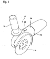
- is a perspective view of an angle grinder according to the present invention.
- Figure 2
- is a side view of a prior art trigger for a powered device. Also illustrated is an angle that approximates the shape of the prior art trigger surface.
- Figure 3
- is a side view of a trigger for a powered device. Also illustrated is an angle that approximates the shape of the trigger surface.
- Figure 4
- is a perspective view of a trigger for a powered device.
- Figure 5
- is a front view of a trigger for a powered device.
- Figure 6
- is a partial side view of a housing of a powered device with the trigger removed.
- Figure 7
- is a partial section view of a powered device with its trigger in the OFF position.
- Figure 8
- is a partial section view of a powered device with its trigger in the ON-UNLOCKED position.
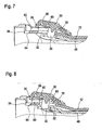
- Figure 9
- is a partial section view of a powered device with its trigger in the ON-LOCKED position.
- Figure 10
- is a schematic view of the coupling between a trigger and a switch.
- A powered device, in this case an
angle grinder 10, is shown inFig. 1 . In this particular device and also in many devices of this type, amotor housing 12 also provides a first operational handle for the user. A secondoperational handle 14 may also be provided so that a user can accurately guide the workingtool 16 driven by the device. A portion of themotor housing 12 is configured with a gently curved but generally flat mountingsurface 18 for mounting an ON-OFF trigger button 20 that is coupled with aswitch 22 that is used to switch the tool between an ON and an OFF state (seeFigs. 6 and10 ). As mentioned, themotor housing 12 can also act as an operational handle by providing apalm gripping surface 24. The gripping of this surface with the user's palm conveniently positions the hand so that his thumb can manipulate ON-OFF trigger button 20. - Although an
angle grinder 10 is illustrated for the purpose of describing the structure of certain embodiments of the invention, the invention is not limited in utility to power tools, or to hand-held devices, or even to electrical devices. Any sort of machinery - irrespective of size - having a source of power and an ON-OFF switch may benefit from the invention. A variety of hand-held items not generally considered to be power tools, such as a hair dryers or the like, may also benefit. Pneumatic devices could benefit, in so far as the flow of their source of power (pressurized gas) can be switched on or off to enable the device. - The
trigger button 20 herein described is separate from and coupled with adistinct switch 22 since this arrangement is often used for economic or design reasons, but it is contemplated that such a trigger may alternatively be an intrinsic part of a switch. - To better describe embodiments of the invention, a prior art ON-OFF trigger button 20' shown in
Fig. 1 will first be described. To facilitate comparison with embodiments of the invention described thereafter, each feature of prior art trigger button 20' will be identified with a prime symbol (i.e., "'"). Certain aspects of theangle grinder 10,motor housing 12 and mountingsurface 18 will be described in the context of prior art trigger button 20', but it should be appreciated that an identical mountingsurface 18 can be utilized with both prior art trigger button 20' andtrigger button 20. - On its top side, trigger button 20' is provided with a first pressing surface 26' and a second pressing surface 28' (see
Fig. 2 ). A paired set of symmetrical or asymmetrical flexible retaining arms 30' is present on the underside of trigger button 20'. These flex so that during assembly they can pass through acavity 32 in the mountingsurface 18 of themotor housing 12 but later resiliently return to their original shape so that paired latching protrusions 34' will retain trigger button 20'. Also on the underside of trigger button 20' is a lockingprotrusion 36' that cooperates with asecond cavity 38 in the mountingsurface 18 to retain trigger button 20' in the locked position that will be described below. The underside also provides paired laterally located pivot protrusions 40' which also contribute to this locking mechanism. -
Trigger button 20 shares these all of these features, including first pressingsurface 26, second pressingsurface 28, flexible retainingarms 30, latchingprotrusions 34, lockingprotrusion 36, and pivot protrusions 40 (seeFigs. 3, 4 and5 ). However, while certain features are shared - and in fact the twotrigger buttons 20, 20' can cooperate with the same mounting surface 18 - the arrangement of the features and the way they cooperate is quite different. - For example in comparing the side views in
Figs. 2 and 3 , it is apparent that the orientation of firstpressing surfaces 26, 26' and secondpressing surfaces 28, 28' with respect to each other is quite different. Though in neither case are the pressing surfaces perfectly flat, they are generally planar so that one can consider the general angle formed between the two surfaces. In prior art trigger button 20', the angle 42' is obtuse, that is, between 90 and 180 degrees, and as illustrated is generally about 150 degrees. In the case oftrigger button 20, theangle 42 is generally a reflex angle, that is, greater than 180 degrees, and as illustrated is generally about 205 degrees. - Although there may or may not be a specific interface between the two pressing surfaces, the surfaces in each case are adjacent each other, so that there are nevertheless
general interfaces 44, 44' between the two pressing surfaces somewhere near the vertex of theangles 42, 42' defined above. The pivot protrusions 40' in the case of prior art trigger button 20' are approximately underneath this interface 44', but thepivot protrusions 40 intrigger button 20 are further away from theinterface 44 and are positioned closer to thelengthwise center 46 of secondpressing surface 28. - As is also the case in for prior art trigger button 20', retaining
arms 30 pass through acavity 32 in the mountingsurface 18 for retainingtrigger button 20, but these retainingarms 30 furthermore pass through aswitch arm 48 present withinmotor housing 12 so that these parts are coupled. Thetop face 50 of each of the paired latchingprotrusions 34 is angled to accommodate rotation oftrigger button 20 since it must nevertheless pass through theswitch arm 48.Switch arm 48 cooperates directly withswitch 22 and is biased by acompression spring 52 in a direction ofarrow 54 so that in the rest position,trigger button 20 is biased into a first "OFF" position as shown inFig. 7 . The arrangement of these features is shown schematically inFig. 10 .Compression spring 52 is positioned between ahousing portion 56 and switcharm 48. Anextension 58 ofswitch arm 28 mechanically activatesswitch 22. -
Trigger button 20 is positioned between two raisedshoulders 60 extending from mountingsurface 18. Raisedshoulders 60 and mountingsurface 18 form a track in which triggerbutton 20 can slide from the OFF position to the other positions. By preferably manipulating first pressingsurface 26, a user can slidetrigger button 20 against the biasing force ofspring 52 so thattrigger button 20 takes on the position shown inFig. 8 . In doing so, lockingprotrusion 36 passes between twoguide shelves 62 which are on either side of lockingprotrusion 36 and thepivot protrusions 40 slide along mountingsurface 18. This is the "ON-UNLOCKED" position, sinceswitch arm 48 in this position will enableswitch 22. - Although in this
position locking protrusion 36 is no longer betweenguide shelves 62 and is position abovecavity 38, further pressure on firstpressing surface 26 can not and does not movetrigger button 20 into the "ON-LOCKED" position inFig. 9 . This can only be accomplished though pressure on secondpressing surface 28 once the button is in the ON-UNLOCKED position.Trigger button 20 is retained in this position due to the force ofspring 52 which pulls the lockingprotrusion 36 against awall 64 ofsecond cavity 38. In addition, the trigger has a partially hollow underside so that aninner wall 66 of thetrigger 20 found on this underside is pulled by the force ofspring 52 into contact withguide shelves 62. Therefore spring 52 acts as biasing means not only for establishing the OFF position but also for retaining the trigger in the ON-LOCKED position. - This splitting of the movement of
trigger button 20 into two phases is realized due to the particular shape oftrigger button 20. In similar circumstances, prior art trigger button 20' works differently. Normally the second pressing surface 28' is engaged for moving from the OFF position to the ON-UNLOCKED position. However, continued pressure on the second pressing surface 28' will also move trigger button 20' further all the way into the ON-LOCKED position. - The movement into the ON-LOCKED position does not involve further axial movement of
trigger button 20 but instead involves a rotation oftrigger button 20 around pivot points created by thepivot protrusions 40 pressing against mountingsurface 18. The pivot protrusions 40 have a curved undersurface 68 to enable this pivoting while at the same timepermit pivot protrusions 40 to slide smoothly along mountingsurface 18 whentrigger button 20 is moved from the OFF position to the ON-UNLOCKED position. - To release
trigger button 20 from the ON-LOCKED position, the user presses with a force normal to firstpressing surface 26. This rotatestrigger button 20 in the opposite direction with respect to pivotprotrusions 40, thereby freeing the lockingprotrusion 36 fromcavity 38 so that the biasing force ofspring 52 will "automatically"return trigger button 20 into the OFF position. Prior art button 20' has a similar release mechanism, in so far as pressure on first pressing surface 26' achieves the same effect. - To facilitate manual manipulation of
trigger button 20,ribs 70 are provided on the first pressingsurface 26. To better fit the shape of a user's thumb, aconcave depression 72 is provided on the secondpressing surface 28, and as best seen inFig. 4 , the first pressingsurface 26 also has a bit of a concave curved shape.
Claims (14)
- A powered device having an ON-OFF mechanism comprising:a housing (12) having a mounting surface (18);a trigger (20) associated with said mounting surface (18) and having an OFF position, an ON-UNLOCKED position, and an ON-LOCKED position, wherein said trigger (20) is coupled with a switch (22) that is used to switch the device between an ON and an OFF state;means for biasing the trigger (52) into the OFF position from the ON-UNLOCKED position; said trigger (20) comprising a first pressing surface (26) for manual movement of the trigger (20) from the OFF position against said biasing means (52) to the ON-UNLOCKED position, and a second pressing surface (28) for manual movement of the trigger (20) from the ON-UNLOCKED position to the ON-LOCKED position, wherein this can only be accomplished through pressure on second pressing surface (28) once the trigger (20) is in the ON-UNLOCKED position; whereinthe first pressing surface (26) and the second pressing surface (28) are generally adjacent to each other and form a reflex angle (42).
- A powered device according to claim 1, characterized in that the housing (12) has two shoulders (60) which extend from the mounting surface (18) and the trigger (20) is positioned between the two shoulders (60).
- A powered device according to any one of the preceding claims, characterized in that the trigger (20) slides along the mounting surface (18) when the trigger (20) is moved from the OFF position to the ON-UNLOCKED position.
- A powered device according to any one of the preceding claims, characterized in that the trigger (20) generally rotates relative to said mounting surface (18) when the trigger (20) is moved from the ON-UNLOCKED position to the ON-LOCKED position.
- A powered device according to any one of the preceding claims, characterized in that said mounting surface (18) has a first cavity (38) for cooperating with a first protrusion (36) on the trigger (20) for locking the trigger (20) into the ON-LOCKED position.
- A powered device according to claim 5, characterized in that the housing (12) has two shelves (62) extending from the mounting surface (18) which are on either side of the first protrusion (36) when the trigger (20) is in the OFF position and which cooperate with the underside (66) of the trigger (20) for locking the trigger in the ON-LOCKED position.
- A powered device according to any one of the preceding claims, characterized in that said mounting surface (18) has a second cavity (32) for cooperating with a second protrusion (30) on the trigger (20) for retaining the trigger (20) onto the housing (12).
- A powered device according to any one of the preceding claims, characterized in that the trigger (20) further comprises a third protrusion (40) that acts as a pivot point when the trigger (20) rotates relative to said mounting surface (18).
- A powered device according to claim 8, characterized in that the third protrusion (40) is positioned lengthwise at a position closer to a center (46) of the second pressing surface (28) than to an interface (44) between the first pressing surface (26) and the second pressing surface (28).
- A powered device according to any one of the preceding claims, characterized in that when the trigger (20) is in the ON-UNLOCKED position, pressure normal to the first pressing surface (26) does not rotate or slide the trigger (20).
- A powered device according to any one of the preceding claims, characterized in that when the trigger (20) is in the OFF position, pressure on the second pressing surface (28) does not rotate or slide the trigger (20).
- A powered device according to any one of the preceding claims, characterized in that when the trigger (20) is in the ON-LOCKED position, pressure on the second pressing surface (28) does not rotate or slide the trigger (20).
- A powered device according to any one of the preceding claims, characterized in that pressure normal to the first pressing surface (26) can be used for manually moving the trigger (20) from the ON-LOCKED position to the ON-UNLOCKED position.
- A powered device according to any one of the preceding claims, characterized in that the powered device is an angle grinder (10).
Applications Claiming Priority (1)
| Application Number | Priority Date | Filing Date | Title |
|---|---|---|---|
| PCT/CN2008/000917 WO2009135338A1 (en) | 2008-05-09 | 2008-05-09 | Powered device having an on-off mechanism |
Publications (3)
| Publication Number | Publication Date |
|---|---|
| EP2285535A1 EP2285535A1 (en) | 2011-02-23 |
| EP2285535A4 EP2285535A4 (en) | 2015-01-28 |
| EP2285535B1 true EP2285535B1 (en) | 2015-10-14 |
Family
ID=41264398
Family Applications (1)
| Application Number | Title | Priority Date | Filing Date |
|---|---|---|---|
| EP08748475.4A Not-in-force EP2285535B1 (en) | 2008-05-09 | 2008-05-09 | Powered device having an on-off mechanism |
Country Status (3)
| Country | Link |
|---|---|
| EP (1) | EP2285535B1 (en) |
| CN (1) | CN102015218B (en) |
| WO (1) | WO2009135338A1 (en) |
Cited By (3)
| Publication number | Priority date | Publication date | Assignee | Title |
|---|---|---|---|---|
| CN104972441A (en) * | 2014-04-11 | 2015-10-14 | 罗伯特·博世有限公司 | Electric Power Tool Having Switching Device |
| US11867224B2 (en) | 2021-01-27 | 2024-01-09 | Black & Decker Inc. | Locking mechanism for two telescoping poles of a power tool |
| US11931851B2 (en) | 2019-10-23 | 2024-03-19 | Black & Decker Inc. | Pole sander |
Families Citing this family (10)
| Publication number | Priority date | Publication date | Assignee | Title |
|---|---|---|---|---|
| DE102011075196A1 (en) | 2011-05-04 | 2012-11-08 | Robert Bosch Gmbh | Machine tool switching device |
| CN102528163B (en) * | 2012-01-06 | 2015-01-07 | 南京德朔实业有限公司 | Palm-shaped sweep saw |
| JP5854914B2 (en) * | 2012-04-20 | 2016-02-09 | 株式会社マキタ | Rechargeable power tool |
| US9954418B2 (en) | 2014-03-17 | 2018-04-24 | Makita Corporation | Power tool |
| DE102014213394A1 (en) * | 2014-07-10 | 2016-01-14 | Robert Bosch Gmbh | Electric machine tool with a slide switch |
| JP6874481B2 (en) * | 2017-03-31 | 2021-05-19 | 工機ホールディングス株式会社 | Electric tool |
| CN107217632A (en) * | 2017-06-06 | 2017-09-29 | 浙江亚特电器有限公司 | A kind of blower of safe operation |
| JP7389652B2 (en) * | 2017-06-12 | 2023-11-30 | アトラス・コプコ・インダストリアル・テクニーク・アクチボラグ | Power wrench with angle drive |
| JP7147871B2 (en) | 2018-11-30 | 2022-10-05 | 工機ホールディングス株式会社 | work machine |
| JP7210261B2 (en) | 2018-12-14 | 2023-01-23 | 株式会社マキタ | ELECTRIC WORKING MACHINE AND METHOD FOR MANUFACTURING STATOR IN MOTOR FOR ELECTRIC WORKING MACHINE |
Family Cites Families (8)
| Publication number | Priority date | Publication date | Assignee | Title |
|---|---|---|---|---|
| DE2450577A1 (en) * | 1974-10-24 | 1976-05-06 | Gloria Werke Schulte H Kg | Electric hand tool switch - which is fitted to battery-operated grass shears or other implement has bow-shaped handle |
| DE3201744A1 (en) * | 1982-01-21 | 1983-07-28 | Karl M. Reich Maschinenfabrik GmbH, 7440 Nürtingen | SWITCHES FOR ELECTRIC TOOLS |
| US4592144A (en) * | 1984-06-22 | 1986-06-03 | The Singer Company | Molded scroller saw lock button spring |
| US5540291A (en) * | 1993-07-23 | 1996-07-30 | Ryobi Outdoor Products | Switch actuator for a portable power tool |
| JPH11277462A (en) * | 1998-03-27 | 1999-10-12 | Makita Corp | Switch mechanism for power tool |
| US6805208B2 (en) * | 2002-08-02 | 2004-10-19 | Black & Decker Inc. | Switch lock-off mechanism for power tools |
| US6812425B1 (en) * | 2003-11-24 | 2004-11-02 | Defond Components Limited | Locking trigger switch mechanism |
| US6989503B2 (en) * | 2004-03-22 | 2006-01-24 | Defond Components Limited | Power tool trigger assembly |
-
2008
- 2008-05-09 CN CN200880129074.8A patent/CN102015218B/en active Active
- 2008-05-09 EP EP08748475.4A patent/EP2285535B1/en not_active Not-in-force
- 2008-05-09 WO PCT/CN2008/000917 patent/WO2009135338A1/en active Application Filing
Cited By (4)
| Publication number | Priority date | Publication date | Assignee | Title |
|---|---|---|---|---|
| CN104972441A (en) * | 2014-04-11 | 2015-10-14 | 罗伯特·博世有限公司 | Electric Power Tool Having Switching Device |
| CN104972441B (en) * | 2014-04-11 | 2019-02-05 | 罗伯特·博世有限公司 | Electric tools with switching device |
| US11931851B2 (en) | 2019-10-23 | 2024-03-19 | Black & Decker Inc. | Pole sander |
| US11867224B2 (en) | 2021-01-27 | 2024-01-09 | Black & Decker Inc. | Locking mechanism for two telescoping poles of a power tool |
Also Published As
| Publication number | Publication date |
|---|---|
| CN102015218B (en) | 2012-07-11 |
| EP2285535A4 (en) | 2015-01-28 |
| WO2009135338A1 (en) | 2009-11-12 |
| EP2285535A1 (en) | 2011-02-23 |
| CN102015218A (en) | 2011-04-13 |
Similar Documents
| Publication | Publication Date | Title |
|---|---|---|
| EP2285535B1 (en) | Powered device having an on-off mechanism | |
| US6861598B2 (en) | Lockout mechanism for power tool | |
| CN112470737B (en) | Hand-guided work apparatus with tool | |
| EP2688715B1 (en) | Hand held power tool with locking rotatable handle | |
| CN106573368B (en) | Electric machine tool | |
| JP5510887B2 (en) | Electric tool | |
| GB2471945A (en) | Locking switch device for a power tool | |
| US6288350B1 (en) | Lockout mechanism for power tool | |
| US8393835B2 (en) | Detachable operating handle for a power tool | |
| KR19980070503A (en) | Multifunctional tool with spring-loaded device | |
| JP6755913B2 (en) | Locking system for use with trigger assemblies in electrical equipment | |
| JP2000173400A (en) | Switch of power tool | |
| US11990294B2 (en) | Switch assembly and power tool | |
| CN212322862U (en) | Switch assembly and electric tool | |
| CN221726978U (en) | Switch handle and hand-held electric tool | |
| WO2024108782A1 (en) | Folding knife | |
| RU2466011C2 (en) | Machine with mechanical drive with on-off mechanism | |
| CN115720773A (en) | Rotary holding device for electric hedge shears | |
| JP2802574B2 (en) | Scissors | |
| JPS6058989B2 (en) | electric razor | |
| JPS59139514A (en) | Locking structure for switch |
Legal Events
| Date | Code | Title | Description |
|---|---|---|---|
| PUAI | Public reference made under article 153(3) epc to a published international application that has entered the european phase |
Free format text: ORIGINAL CODE: 0009012 |
|
| 17P | Request for examination filed |
Effective date: 20101209 |
|
| AK | Designated contracting states |
Kind code of ref document: A1 Designated state(s): AT BE BG CH CY CZ DE DK EE ES FI FR GB GR HR HU IE IS IT LI LT LU LV MC MT NL NO PL PT RO SE SI SK TR |
|
| AX | Request for extension of the european patent |
Extension state: AL BA MK RS |
|
| DAX | Request for extension of the european patent (deleted) | ||
| A4 | Supplementary search report drawn up and despatched |
Effective date: 20150109 |
|
| RIC1 | Information provided on ipc code assigned before grant |
Ipc: H01H 3/20 20060101ALI20141223BHEP Ipc: B25F 5/00 20060101AFI20141223BHEP Ipc: H01H 9/06 20060101ALI20141223BHEP |
|
| RIC1 | Information provided on ipc code assigned before grant |
Ipc: B25F 5/00 20060101AFI20150415BHEP Ipc: H01H 3/20 20060101ALI20150415BHEP Ipc: H01H 9/06 20060101ALI20150415BHEP |
|
| GRAP | Despatch of communication of intention to grant a patent |
Free format text: ORIGINAL CODE: EPIDOSNIGR1 |
|
| INTG | Intention to grant announced |
Effective date: 20150618 |
|
| GRAS | Grant fee paid |
Free format text: ORIGINAL CODE: EPIDOSNIGR3 |
|
| GRAA | (expected) grant |
Free format text: ORIGINAL CODE: 0009210 |
|
| AK | Designated contracting states |
Kind code of ref document: B1 Designated state(s): AT BE BG CH CY CZ DE DK EE ES FI FR GB GR HR HU IE IS IT LI LT LU LV MC MT NL NO PL PT RO SE SI SK TR |
|
| REG | Reference to a national code |
Ref country code: GB Ref legal event code: FG4D |
|
| REG | Reference to a national code |
Ref country code: AT Ref legal event code: REF Ref document number: 754753 Country of ref document: AT Kind code of ref document: T Effective date: 20151015 Ref country code: CH Ref legal event code: EP |
|
| REG | Reference to a national code |
Ref country code: IE Ref legal event code: FG4D |
|
| REG | Reference to a national code |
Ref country code: DE Ref legal event code: R096 Ref document number: 602008040655 Country of ref document: DE |
|
| REG | Reference to a national code |
Ref country code: NL Ref legal event code: MP Effective date: 20151014 |
|
| REG | Reference to a national code |
Ref country code: LT Ref legal event code: MG4D |
|
| REG | Reference to a national code |
Ref country code: AT Ref legal event code: MK05 Ref document number: 754753 Country of ref document: AT Kind code of ref document: T Effective date: 20151014 |
|
| PG25 | Lapsed in a contracting state [announced via postgrant information from national office to epo] |
Ref country code: NL Free format text: LAPSE BECAUSE OF FAILURE TO SUBMIT A TRANSLATION OF THE DESCRIPTION OR TO PAY THE FEE WITHIN THE PRESCRIBED TIME-LIMIT Effective date: 20151014 Ref country code: ES Free format text: LAPSE BECAUSE OF FAILURE TO SUBMIT A TRANSLATION OF THE DESCRIPTION OR TO PAY THE FEE WITHIN THE PRESCRIBED TIME-LIMIT Effective date: 20151014 Ref country code: NO Free format text: LAPSE BECAUSE OF FAILURE TO SUBMIT A TRANSLATION OF THE DESCRIPTION OR TO PAY THE FEE WITHIN THE PRESCRIBED TIME-LIMIT Effective date: 20160114 Ref country code: LT Free format text: LAPSE BECAUSE OF FAILURE TO SUBMIT A TRANSLATION OF THE DESCRIPTION OR TO PAY THE FEE WITHIN THE PRESCRIBED TIME-LIMIT Effective date: 20151014 Ref country code: IS Free format text: LAPSE BECAUSE OF FAILURE TO SUBMIT A TRANSLATION OF THE DESCRIPTION OR TO PAY THE FEE WITHIN THE PRESCRIBED TIME-LIMIT Effective date: 20160214 Ref country code: HR Free format text: LAPSE BECAUSE OF FAILURE TO SUBMIT A TRANSLATION OF THE DESCRIPTION OR TO PAY THE FEE WITHIN THE PRESCRIBED TIME-LIMIT Effective date: 20151014 Ref country code: IT Free format text: LAPSE BECAUSE OF FAILURE TO SUBMIT A TRANSLATION OF THE DESCRIPTION OR TO PAY THE FEE WITHIN THE PRESCRIBED TIME-LIMIT Effective date: 20151014 |
|
| PG25 | Lapsed in a contracting state [announced via postgrant information from national office to epo] |
Ref country code: PT Free format text: LAPSE BECAUSE OF FAILURE TO SUBMIT A TRANSLATION OF THE DESCRIPTION OR TO PAY THE FEE WITHIN THE PRESCRIBED TIME-LIMIT Effective date: 20160215 Ref country code: LV Free format text: LAPSE BECAUSE OF FAILURE TO SUBMIT A TRANSLATION OF THE DESCRIPTION OR TO PAY THE FEE WITHIN THE PRESCRIBED TIME-LIMIT Effective date: 20151014 Ref country code: FI Free format text: LAPSE BECAUSE OF FAILURE TO SUBMIT A TRANSLATION OF THE DESCRIPTION OR TO PAY THE FEE WITHIN THE PRESCRIBED TIME-LIMIT Effective date: 20151014 Ref country code: PL Free format text: LAPSE BECAUSE OF FAILURE TO SUBMIT A TRANSLATION OF THE DESCRIPTION OR TO PAY THE FEE WITHIN THE PRESCRIBED TIME-LIMIT Effective date: 20151014 Ref country code: GR Free format text: LAPSE BECAUSE OF FAILURE TO SUBMIT A TRANSLATION OF THE DESCRIPTION OR TO PAY THE FEE WITHIN THE PRESCRIBED TIME-LIMIT Effective date: 20160115 Ref country code: SE Free format text: LAPSE BECAUSE OF FAILURE TO SUBMIT A TRANSLATION OF THE DESCRIPTION OR TO PAY THE FEE WITHIN THE PRESCRIBED TIME-LIMIT Effective date: 20151014 Ref country code: AT Free format text: LAPSE BECAUSE OF FAILURE TO SUBMIT A TRANSLATION OF THE DESCRIPTION OR TO PAY THE FEE WITHIN THE PRESCRIBED TIME-LIMIT Effective date: 20151014 |
|
| REG | Reference to a national code |
Ref country code: DE Ref legal event code: R097 Ref document number: 602008040655 Country of ref document: DE |
|
| PG25 | Lapsed in a contracting state [announced via postgrant information from national office to epo] |
Ref country code: CZ Free format text: LAPSE BECAUSE OF FAILURE TO SUBMIT A TRANSLATION OF THE DESCRIPTION OR TO PAY THE FEE WITHIN THE PRESCRIBED TIME-LIMIT Effective date: 20151014 |
|
| PLBE | No opposition filed within time limit |
Free format text: ORIGINAL CODE: 0009261 |
|
| STAA | Information on the status of an ep patent application or granted ep patent |
Free format text: STATUS: NO OPPOSITION FILED WITHIN TIME LIMIT |
|
| PG25 | Lapsed in a contracting state [announced via postgrant information from national office to epo] |
Ref country code: SK Free format text: LAPSE BECAUSE OF FAILURE TO SUBMIT A TRANSLATION OF THE DESCRIPTION OR TO PAY THE FEE WITHIN THE PRESCRIBED TIME-LIMIT Effective date: 20151014 Ref country code: DK Free format text: LAPSE BECAUSE OF FAILURE TO SUBMIT A TRANSLATION OF THE DESCRIPTION OR TO PAY THE FEE WITHIN THE PRESCRIBED TIME-LIMIT Effective date: 20151014 Ref country code: BE Free format text: LAPSE BECAUSE OF NON-PAYMENT OF DUE FEES Effective date: 20160531 Ref country code: RO Free format text: LAPSE BECAUSE OF FAILURE TO SUBMIT A TRANSLATION OF THE DESCRIPTION OR TO PAY THE FEE WITHIN THE PRESCRIBED TIME-LIMIT Effective date: 20151014 Ref country code: EE Free format text: LAPSE BECAUSE OF FAILURE TO SUBMIT A TRANSLATION OF THE DESCRIPTION OR TO PAY THE FEE WITHIN THE PRESCRIBED TIME-LIMIT Effective date: 20151014 |
|
| 26N | No opposition filed |
Effective date: 20160715 |
|
| PG25 | Lapsed in a contracting state [announced via postgrant information from national office to epo] |
Ref country code: SI Free format text: LAPSE BECAUSE OF FAILURE TO SUBMIT A TRANSLATION OF THE DESCRIPTION OR TO PAY THE FEE WITHIN THE PRESCRIBED TIME-LIMIT Effective date: 20151014 |
|
| PG25 | Lapsed in a contracting state [announced via postgrant information from national office to epo] |
Ref country code: LU Free format text: LAPSE BECAUSE OF FAILURE TO SUBMIT A TRANSLATION OF THE DESCRIPTION OR TO PAY THE FEE WITHIN THE PRESCRIBED TIME-LIMIT Effective date: 20160509 Ref country code: BE Free format text: LAPSE BECAUSE OF FAILURE TO SUBMIT A TRANSLATION OF THE DESCRIPTION OR TO PAY THE FEE WITHIN THE PRESCRIBED TIME-LIMIT Effective date: 20151014 |
|
| REG | Reference to a national code |
Ref country code: CH Ref legal event code: PL |
|
| GBPC | Gb: european patent ceased through non-payment of renewal fee |
Effective date: 20160509 |
|
| PG25 | Lapsed in a contracting state [announced via postgrant information from national office to epo] |
Ref country code: CH Free format text: LAPSE BECAUSE OF NON-PAYMENT OF DUE FEES Effective date: 20160531 Ref country code: LI Free format text: LAPSE BECAUSE OF NON-PAYMENT OF DUE FEES Effective date: 20160531 |
|
| REG | Reference to a national code |
Ref country code: IE Ref legal event code: MM4A |
|
| REG | Reference to a national code |
Ref country code: FR Ref legal event code: ST Effective date: 20170131 |
|
| PG25 | Lapsed in a contracting state [announced via postgrant information from national office to epo] |
Ref country code: FR Free format text: LAPSE BECAUSE OF NON-PAYMENT OF DUE FEES Effective date: 20160531 |
|
| PG25 | Lapsed in a contracting state [announced via postgrant information from national office to epo] |
Ref country code: GB Free format text: LAPSE BECAUSE OF NON-PAYMENT OF DUE FEES Effective date: 20160509 Ref country code: IE Free format text: LAPSE BECAUSE OF NON-PAYMENT OF DUE FEES Effective date: 20160509 |
|
| PG25 | Lapsed in a contracting state [announced via postgrant information from national office to epo] |
Ref country code: HU Free format text: LAPSE BECAUSE OF FAILURE TO SUBMIT A TRANSLATION OF THE DESCRIPTION OR TO PAY THE FEE WITHIN THE PRESCRIBED TIME-LIMIT; INVALID AB INITIO Effective date: 20080509 Ref country code: CY Free format text: LAPSE BECAUSE OF FAILURE TO SUBMIT A TRANSLATION OF THE DESCRIPTION OR TO PAY THE FEE WITHIN THE PRESCRIBED TIME-LIMIT Effective date: 20151014 |
|
| PG25 | Lapsed in a contracting state [announced via postgrant information from national office to epo] |
Ref country code: MT Free format text: LAPSE BECAUSE OF NON-PAYMENT OF DUE FEES Effective date: 20160531 Ref country code: MC Free format text: LAPSE BECAUSE OF FAILURE TO SUBMIT A TRANSLATION OF THE DESCRIPTION OR TO PAY THE FEE WITHIN THE PRESCRIBED TIME-LIMIT Effective date: 20151014 Ref country code: TR Free format text: LAPSE BECAUSE OF FAILURE TO SUBMIT A TRANSLATION OF THE DESCRIPTION OR TO PAY THE FEE WITHIN THE PRESCRIBED TIME-LIMIT Effective date: 20151014 |
|
| REG | Reference to a national code |
Ref country code: DE Ref legal event code: R081 Ref document number: 602008040655 Country of ref document: DE Owner name: ROBERT BOSCH GMBH, DE Free format text: FORMER OWNER: BOSCH POWER TOOLS (CHINA) CO., LTD., HANGZHOU, ZHEJIANG, CN |
|
| PG25 | Lapsed in a contracting state [announced via postgrant information from national office to epo] |
Ref country code: BG Free format text: LAPSE BECAUSE OF FAILURE TO SUBMIT A TRANSLATION OF THE DESCRIPTION OR TO PAY THE FEE WITHIN THE PRESCRIBED TIME-LIMIT Effective date: 20151014 |
|
| PGFP | Annual fee paid to national office [announced via postgrant information from national office to epo] |
Ref country code: DE Payment date: 20190716 Year of fee payment: 12 |
|
| REG | Reference to a national code |
Ref country code: DE Ref legal event code: R119 Ref document number: 602008040655 Country of ref document: DE |
|
| PG25 | Lapsed in a contracting state [announced via postgrant information from national office to epo] |
Ref country code: DE Free format text: LAPSE BECAUSE OF NON-PAYMENT OF DUE FEES Effective date: 20201201 |