EP2284969A1 - Cord seal for swimming pool and spa light niches - Google Patents
Cord seal for swimming pool and spa light niches Download PDFInfo
- Publication number
- EP2284969A1 EP2284969A1 EP10186179A EP10186179A EP2284969A1 EP 2284969 A1 EP2284969 A1 EP 2284969A1 EP 10186179 A EP10186179 A EP 10186179A EP 10186179 A EP10186179 A EP 10186179A EP 2284969 A1 EP2284969 A1 EP 2284969A1
- Authority
- EP
- European Patent Office
- Prior art keywords
- seal
- main seal
- cord
- main
- split
- Prior art date
- Legal status (The legal status is an assumption and is not a legal conclusion. Google has not performed a legal analysis and makes no representation as to the accuracy of the status listed.)
- Withdrawn
Links
- 230000009182 swimming Effects 0.000 title 1
- XLYOFNOQVPJJNP-UHFFFAOYSA-N water Substances O XLYOFNOQVPJJNP-UHFFFAOYSA-N 0.000 claims description 16
- 238000000034 method Methods 0.000 claims 3
- 229920001971 elastomer Polymers 0.000 description 6
- 238000009434 installation Methods 0.000 description 4
- 238000000605 extraction Methods 0.000 description 3
- 239000004590 silicone sealant Substances 0.000 description 3
- 238000003780 insertion Methods 0.000 description 2
- 230000037431 insertion Effects 0.000 description 2
- 239000000463 material Substances 0.000 description 2
- 239000000565 sealant Substances 0.000 description 2
- 238000007789 sealing Methods 0.000 description 2
- 229920002943 EPDM rubber Polymers 0.000 description 1
- 230000007797 corrosion Effects 0.000 description 1
- 238000005260 corrosion Methods 0.000 description 1
- 230000008030 elimination Effects 0.000 description 1
- 238000003379 elimination reaction Methods 0.000 description 1
- 239000003292 glue Substances 0.000 description 1
- 238000002347 injection Methods 0.000 description 1
- 239000007924 injection Substances 0.000 description 1
- 239000002184 metal Substances 0.000 description 1
- 239000004033 plastic Substances 0.000 description 1
- 229920001296 polysiloxane Polymers 0.000 description 1
- 239000003566 sealing material Substances 0.000 description 1
- 239000000243 solution Substances 0.000 description 1
Images
Classifications
-
- H—ELECTRICITY
- H02—GENERATION; CONVERSION OR DISTRIBUTION OF ELECTRIC POWER
- H02G—INSTALLATION OF ELECTRIC CABLES OR LINES, OR OF COMBINED OPTICAL AND ELECTRIC CABLES OR LINES
- H02G3/00—Installations of electric cables or lines or protective tubing therefor in or on buildings, equivalent structures or vehicles
- H02G3/22—Installations of cables or lines through walls, floors or ceilings, e.g. into buildings
-
- H—ELECTRICITY
- H02—GENERATION; CONVERSION OR DISTRIBUTION OF ELECTRIC POWER
- H02G—INSTALLATION OF ELECTRIC CABLES OR LINES, OR OF COMBINED OPTICAL AND ELECTRIC CABLES OR LINES
- H02G3/00—Installations of electric cables or lines or protective tubing therefor in or on buildings, equivalent structures or vehicles
- H02G3/02—Details
- H02G3/08—Distribution boxes; Connection or junction boxes
- H02G3/088—Dustproof, splashproof, drip-proof, waterproof, or flameproof casings or inlets
-
- H—ELECTRICITY
- H02—GENERATION; CONVERSION OR DISTRIBUTION OF ELECTRIC POWER
- H02G—INSTALLATION OF ELECTRIC CABLES OR LINES, OR OF COMBINED OPTICAL AND ELECTRIC CABLES OR LINES
- H02G3/00—Installations of electric cables or lines or protective tubing therefor in or on buildings, equivalent structures or vehicles
- H02G3/02—Details
- H02G3/08—Distribution boxes; Connection or junction boxes
- H02G3/18—Distribution boxes; Connection or junction boxes providing line outlets
- H02G3/20—Ceiling roses or other lighting sets
-
- F—MECHANICAL ENGINEERING; LIGHTING; HEATING; WEAPONS; BLASTING
- F21—LIGHTING
- F21V—FUNCTIONAL FEATURES OR DETAILS OF LIGHTING DEVICES OR SYSTEMS THEREOF; STRUCTURAL COMBINATIONS OF LIGHTING DEVICES WITH OTHER ARTICLES, NOT OTHERWISE PROVIDED FOR
- F21V27/00—Cable-stowing arrangements structurally associated with lighting devices, e.g. reels
- F21V27/02—Cable inlets
-
- F—MECHANICAL ENGINEERING; LIGHTING; HEATING; WEAPONS; BLASTING
- F21—LIGHTING
- F21V—FUNCTIONAL FEATURES OR DETAILS OF LIGHTING DEVICES OR SYSTEMS THEREOF; STRUCTURAL COMBINATIONS OF LIGHTING DEVICES WITH OTHER ARTICLES, NOT OTHERWISE PROVIDED FOR
- F21V31/00—Gas-tight or water-tight arrangements
-
- F—MECHANICAL ENGINEERING; LIGHTING; HEATING; WEAPONS; BLASTING
- F21—LIGHTING
- F21W—INDEXING SCHEME ASSOCIATED WITH SUBCLASSES F21K, F21L, F21S and F21V, RELATING TO USES OR APPLICATIONS OF LIGHTING DEVICES OR SYSTEMS
- F21W2131/00—Use or application of lighting devices or systems not provided for in codes F21W2102/00-F21W2121/00
- F21W2131/40—Lighting for industrial, commercial, recreational or military use
- F21W2131/401—Lighting for industrial, commercial, recreational or military use for swimming pools
-
- Y—GENERAL TAGGING OF NEW TECHNOLOGICAL DEVELOPMENTS; GENERAL TAGGING OF CROSS-SECTIONAL TECHNOLOGIES SPANNING OVER SEVERAL SECTIONS OF THE IPC; TECHNICAL SUBJECTS COVERED BY FORMER USPC CROSS-REFERENCE ART COLLECTIONS [XRACs] AND DIGESTS
- Y10—TECHNICAL SUBJECTS COVERED BY FORMER USPC
- Y10T—TECHNICAL SUBJECTS COVERED BY FORMER US CLASSIFICATION
- Y10T29/00—Metal working
- Y10T29/49—Method of mechanical manufacture
- Y10T29/49826—Assembling or joining
Definitions
- the present invention relates to a pool and spa underwater light niche. More specifically, the present invention relates to a cord seal for an underwater light to prevent water from entering the electrical conduit.
- Underwater lighting has generally been employed in pools, spas and the like to enhance the attractiveness and safety of the water.
- the underwater light is typically installed in either a wet or dry niche located in the pool wall.
- wet niche applications where water resides inside the niche, it is desirable to prevent water from entering the electrical conduit, which carries the power cord and grounding cord for the light. If the conduit is not sealed off from the pool water, chemically active water resides in the conduit, thus, creating a risk of corrosion. Further, any damage to the underground conduit will cause a pool leak that is difficult to locate. The threat of a pool leak that cannot be located causes many builders to specify a more costly metal conduit rather than the plastic conduit.
- One solution to prevent water from entering the electrical conduit is to inject a silicone sealant into the conduit and around the power and ground cord.
- the silicone sealant may or may not provide an adequate seal. Further, the injection of the silicone sealant makes it difficult to replace the light because the silicone glues the power and ground cords into the conduit.
- a seal that overcomes that solves the problems discussed above, including making it easier to replace a light and accommodating a power and a ground cord of different dimensions.
- the present invention overcomes these problems by providing a deformable seal having a split design.
- the split design allows the seal to be installed after the power and ground cords are installed. Further, the present invention can accommodate two cords of different diameters.
- the present invention can be installed before a pool is filled with water. Passage of water into the conduit will be prevented by the present invention.
- a cord seal for use in an underwater niche comprises a seal cap and a main seal having a front side and a rear side and the main seal further includes a plurality of passages that are accessible from the front side and the rear side.
- the main seal also includes at least one split where the main seal is deformable to provide a water-tight seal.
- the invention may take physical form in certain parts and arrangement of parts, a preferred embodiment of which will be described in detail in this specification and illustrated in the accompanying drawings that form a part of the specification.
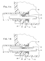
- FIGURE 1A is a partial side view of an underwater niche showing the present invention installed with one wire.
- FIGURE 1B is a partial side view of an underwater niche showing the present invention installed with two wires.
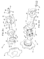
- FIGURES 2A and 2B are exploded views of the present invention shown in opposite directions.
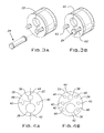
- FIGURES 3A and 3B are an assembled perspective view of the present invention with a cylindrical seal exploded and inserted respectively.
- FIGURES 4A and 4B are front and rear views respectively of a main seal.
- the present invention is a cord seal device that contains a split seal device.
- the present invention can also contain additional supporting pieces to aid in forming the seal.
- the support pieces may be placed above and below the main seal. Each of these supporting pieces can be made in halves.
- the support pieces are attached to a main seal by having a plurality of projections that connect with apertures and cavities in the main seal.
- the assembly can then be pried open along at least one split in the main seal for installation and removal of either a lamp cord and a grounding or bonding wire.
- the lamp cord and the grounding wire fit into passages in the main seal.
- the split in the main seal allows easier assembly of the underwater light assembly and allows for the elimination of the use of any sealant.
- the main seal acts as a spring by deforming in response to a force applied to the cord seal, such as by a seal cap.
- the seal cap forces the material of the main seal, such as rubber, to fill the gaps around the lamp cord and the grounding wire and also fills any other small gaps between the main seal in a niche.
- the deformation of the main seal results in a water-tight seal around the lamp cord passage and a grounding wire passage so that the split does not affect the seal of the device.
- the cord seal 20 in one embodiment may contain only a seal cap 30 and a main seal 22 as long as the seal cap 30 is tightened by a plurality of screws.
- the seal cap 30 tightens by rotating on a thread and the cord seal 20 may contain at least one additional support pieces.
- the additional support pieces may be comprised of a front seal support 26 and/or a rear seal support 28 to allow free rotation of the seal cap 30 without tearing the soft rubber seal and the support pieces are composed of a harder material than the main seal.
- An embodiment containing both the front seal support 26 and the rear seal support 28 is shown in FIGURES 2A, 2B , 3A, 3B, 4A, and 4B . In the embodiment where the seal cap 30 has threads, these threads mate with the threads of the hub 12, as shown in FIGURES 1A and 1B .
- FIGURES 1A and 1B show the different installation configurations of a cord seal 20 in accordance with the present invention.
- FIGURE 1A shows a single wire installation
- FIGURE 1B shows a two-wire installation.
- FIGURE 1A shows a partial cross-sectional side view of an underwater niche 10 showing the cord seal 20 comprising a main seal 22, front seal support 26, a rear seal support 28, and a seal cap 30.
- the cord seal 20 is installed in a hub 12 with a lamp cord 14 and a cylindrical seal 24.
- FIGURE 1B shows the same underwater niche 10 with the cord seal 20 installed in the hub 12 with the lamp cord 14 and a grounding wire 16 instead of a cylindrical seal 24.
- FIGURES 2A and 2B show exploded views of the cord seal 20.
- the cord seal 20 includes a main seal 22, a cylindrical seal 24, a front seal support 26, a rear seal support 28, and a seal cap 30.
- the cylindrical seal 24 that is used in place of the grounding wire 16 in single wire applications may include a seal body 50 and a stop portion 52 located at each end of the seal body 50. Each stop portion 52 has a diameter larger than the seal body 50.
- the stop portion 52 contacts a front side of the front seal support 26 and the other stop portion 52 contacts a back side of the rear seal support 28. Therefore, when installed, the stop portion 52 prevents the cylindrical seal 24 from sliding and becoming dislodged from the main seal 22.
- additional supporting pieces may be included with the cord seal 20 and that the seal body 50 would have a larger length to accommodate the additional structures.
- One stop portion 52 would contact a front side of a supporting piece that is the greatest distance from the seal cap 30 and the other stop portion would contact a back side of a supporting piece that is closest to the seal cap 30.
- the front seal support 26 is comprised of two halves, a front left half 54 and a front right half 56.
- Each half 54, 56 includes two semi-circles 58, 60.
- the first semi-circle 58 has approximately the same radius as a cord receiving passage 36 located on the main seal 22 and the second semi-circle 60 has approximately the same radius as a wire receiving passage 38 on the main seal 22.
- the first semi-circle 58 from each half 54, 56 forms an aperture that has the same diametric center as the cord receiving passage 36 to receive the lamp cord 14.
- the second semi-circle 60 from each half 54, 56 forms a circumference that has the same diametric center as the wire receiving passage 38 thereby receiving either the cylindrical seal 24 or the grounding wire 16. It is to be appreciated that the exploded views presented in FIGURES 2A and 2B may include a grounding wire 16 instead of a cylindrical seal 24.
- a plurality of fastening projections 62 extend substantially perpendicular from a rear side 64 of each half 54, 56 of the front seal support 26.
- each fastening projection 62 penetrates one of a plurality of fastening apertures 40 on the main seal 22 thereby securing the front seal support 26 to the main seal 22.
- the location of the fastening apertures 40 in one embodiment is shown in FIGURES 4A and 4B and will be described more specifically further below.
- the rear seal support 28 is also comprised of two halves in this embodiment, a rear left half 66 and a rear right half 68.
- Each half 66, 68 includes a flange portion 69 that has a radius slightly larger than each half 66, 68. This flange portion 69 provides a stop against an inner portion of the hub 12 when the cord seal 10 is installed so as to prevent over tightening.
- Each half 66, 68 further includes two semi-circles 70, 72.
- the first semi-circle 70 has approximately the same radius as the cord receiving passage 36 and the second semi-circle 72 has approximately the same radius as the wire receiving passage 38 on the main seal 22.
- the first semi-circle 70 from each half 66, 68 forms a passage that has the same circumference as the cord receiving passage 36 thereby receiving the lamp cord 14.
- the second semi-circle 72 from each half 66, 68 forms a passage that has the same circumference as the wire receiving passage 38 thereby receiving either the cylindrical seal 24 or the grounding wire 16.
- At least one fastening stub 74 extends substantially perpendicular from a front side 76 of each half 66, 68. When the cord seal 20 is installed the fastening stubs 74 penetrate a plurality of cavities 48 on the main seal 22 to thereby secure the rear seal support 28 to the main seal 22.
- Each half 66, 68 further includes an alignment aperture 78.
- the alignment apertures 78 have the same diametric center as the fastening apertures 40.
- FIGURES 3A and 3B an embodiment of a fully assembled cord seal is shown using a cylindrical seal 24.
- the fastening projections 62 extend through the main seal 22 and extend into and out of the rear seal support.
- the portion extending out the back of the rear seal support 28 allows the lamp cord 14 to be easily installed and removed with an extraction tool such as pliers.
- the user can spread apart the main seal 22 by using an extraction tool to grasp the fastening projections 62.
- Providing a front seal support 26 with two halves 54, 56 and a rear seal support 28 with two halves 66, 68 allows for the support pieces to also spread apart.
- the fastening projections 62 aid in holding the cord seal together as one structure.
- the main seal 22 can be made of any type of sealing material known in the art such as rubber.
- the main seal 22 is made from a deformable rubber and more specifically from EPDM.
- the main seal 22 is circular in shape and has an overall diameter and thickness to fit a standard sized hub 12 for an underwater niche 10 in a pool, spa, and the like.
- the main seal 22 has a front 32 and a rear 34 side and includes a plurality of passages 36, 38 and a plurality of apertures 40 which are accessible from the front side 32 and the rear side 34.
- the multiple passages include a cord receiving passage 36 and a wire receiving passage 38.
- the multiple apertures include at least two fastening apertures 40.
- the main seal 22 further includes a plurality of cavities 48 located on the rear side 34, as seen in FIGURE 4B .
- the multiple cavities 48 receive a plurality of fastening stubs 74 extending from the rear seal support 28.
- the cord receiving passage 36 receives the lamp cord 14 as shown in FIGURES 1A and 1B .
- the main seal 22 is a one piece design.
- the main seal 22 includes a first split 42.
- the first split 42 is accessible from the front side 32 and the rear side 34 of the main seal 22 and from the cord receiving passage 36 to the outer circumferential edge of the main seal 22.
- the lamp cord 14 is inserted into the cord receiving passage 36 by simply spreading the main seal 22 at the location of the first split 42.
- the tightening of the seal cap 30 causes the main seal to deform thereby causing both sides of the first split 42 to tightly compress against each other, thus, forming a seal.
- the tightening of the seal cap 30 deforms the rubber to fill the gap around the wires and any other small gaps between the rubber and cavity walls or other components. Therefore, even though the cord seal 20 has a split design the deformity of the main seal 22 prevents water from flowing into the electrical conduit through the first split 42.
- the wire receiving passage 38 receives a cylindrical object, and can have one of two functions depending on the application.
- the wire receiving passage 38 receives the cylindrical seal 24 in a single wire application as shown in FIGURE 1A and receives the grounding wire 16 in a two-wire application as shown in FIGURE 1B .
- the main seal 22 includes a second split 44 diametrically opposite from the first split 42.
- the second split 44 is accessible from the front side 32 and the rear side 34 of the main seal 22 and from the wire receiving passage 38 to the outer circumferential edge of the main seal 22.
- the cylindrical seal 24 or the grounding wire 16 is inserted into the wire receiving passage 38 by simply spreading the main seal 22 at the location of the second split 44.
- the grounding wire 16 is a #8 bonding wire.
- the tightening of the seal cap 30 causes the main seal 22 to deform thereby causing both sides of the second split 44 to tightly compress against each other, thus, forming a seal. Therefore, even though the cord seal 20 has a split design the deformity of the main seal 22 prevents water from flowing into the electrical conduit through the second split 44.
- the apertures are equal in diameter and are located on opposite sides of an axis 46 formed by the first 42 and second 44 splits.
- Each fastening aperture 40 receives a fastening projection 62 extending from the front seal support 26, as seen in FIGURE 2A and 2B .
- the number of fastening apertures 40 can be any number as long as there is at least one fastening aperture 40 on each side of the axis 46. In the embodiment shown, the number of fastening apertures 40 is four.
- the main seal 22 includes multiple cavities 48 located on the rear side 34 of the main seal 22.
- Each cavity 48 receives a fastening stub 74 extending from the rear seal support 28, as seen in FIGURE 2A and 2B .
- the number of cavities 48 can be any number as long as there is at least one cavity 48 on each side of the axis 46. In the embodiment shown, the number of cavities 48 is four, two on either side of the axis 46.
- a niche in a wall can house a lighting structure, where the lighting structure is connected by an electrical conduit to a power source located on the exterior of the niche.
- the main seal is connected between the lighting structure and the electrical conduit to prevent water from entering the electrical conduit and the exterior of the niche.
- the seal cap is placed in physical contact with one side of the main seal.
- a cord is then routed through the exterior of the niche in the electrical conduit, through the main seal, and into the interior of the niche wherein the cord is routed through the main seal by spreading apart the main seal at the location of a first split in the main seal.
- the main seal is deformable in response to the physical contact of the seal to provide a water-tight seal.
- the lamp cord 14 and the grounding wire 16 will be routed into the inside of the niche 10 through the seal cap 30 and into the conduit.
- the required length of the lamp cord 14 is pulled into the niche 10.
- the grounding wire 16 is pulled through the niche 10 with enough slack to connect to a bonding lug (not shown).
- the main seal 22 is grasped.
- the main seal 22 should be spread apart at the location of the first split 42 to allow for passage of the lamp cord 14 at the cord receiving passage 36.
- the main seal 22 should be spread apart at the location of the second split 44 to allow for passage of the grounding wire 16 at the wire receiving passage 38.
- the main seal 22 can be spread apart by the aid of pulling apart the fastening projections 62 from the front seal support 26.
- the orientation of the main seal in this embodiment, is such that if a front seal support 26 is used, the fastening projections 62 from the front seal support 26 will be oriented towards the seal cap 30.
- the seal cap 30 can be turned clockwise two or three turns to facilitate a partial connection.
- the end of the grounding wire 16 extending out of the cord seal 20 should be connected to a lug (not shown) inside the niche 10.
- a screw is used to secure the grounding wire 16 to the lug, but the user must ensure that the wire has sufficient slack to allow for removal of the seal cap 30 and the cord seal 20 in the future. Due to the seal cap 30 only being partially connected, the length of the lamp cord 14 and the grounding wire 16 should still be adjustable by gently tugging on either wire.
- the connection between the grounding wire and the lug should be sealed, such as by the use of a 3M Scotchcast 2135 sealant.
- the seal cap 30 should be connected fully, or in one embodiment turned clockwise as much as possible. The turning of the seal cap 30 will secure and lock the cord seal 20, and the lengths of the lamp cord and the grounding wire will no longer be adjustable. The user can then tug on the lamp cord and the grounding wire to ensure that they do not move.
- the cord seal 20 will form a water-tight seal so that water cannot enter the conduit from inside of the niche.
- the cylindrical seal 24 should be inserted into the wire receiving passage 38. Furthermore, there will be no steps for installing that involve the grounding lug.
- the light assembly should be removed from the niche 10 and the wire that is connected to the existing light, the lamp cord 14, should be cut.
- the seal cap 30 should be unscrewed form the hub 12 in the niche.
- the lamp cord 14 should then be pulled slightly to loosen the cord seal 20 from the threaded hub 12.
- each of the fastening projections 62 should be gently pulled to spread apart the main seal 22 to provide access for removing the lamp cord 14.
- the grounding wire 16 and the lamp cord 14 should then be removed from the main seal 22.
- the main seal 22 should then be removed from any supporting pieces and removed from the niche 10.
- the grounding wire should still be connected to the lug inside the niche.
- a cylindrical seal 24 would only need to be removed from the main seal 22, as opposed to a grounding wire 16.
- a new lamp cord 14 should be inserted through the seal cap 30.
- the new main seal 22 should be attached to any supporting pieces and should be spread apart at the first split 42 for insertion of the lamp cord 14.
- the second split 44 of the main seal 22 should be spread apart for insertion of the grounding wire 16 or the cylindrical seal 24.
- the length of the lamp cord 14 should still be adjustable by gently tugging on the lamp cord 14.
- the seal cap 30 should be connected fully, or in one embodiment turned clockwise as much as possible. The turning of the seal cap 30 will secure and lock the cord seal 20, and the length of the lamp cord will no longer be adjustable. The user can then tug on the lamp cord 14 to ensure that it does not move.
- the grounding wire 16 should still be connected to a lug (not shown) inside the niche 10.
- the cord seal 20 will form a water-tight seal so that water cannot enter the conduit from inside the niche.
Landscapes
- Engineering & Computer Science (AREA)
- Architecture (AREA)
- Civil Engineering (AREA)
- Structural Engineering (AREA)
- Instruments For Viewing The Inside Of Hollow Bodies (AREA)
- Connector Housings Or Holding Contact Members (AREA)
Abstract
Description
- Benefit of
U.S. Provisional Patent Application Serial Number 60/730,636, filed October 27, 2005 - The present invention relates to a pool and spa underwater light niche. More specifically, the present invention relates to a cord seal for an underwater light to prevent water from entering the electrical conduit.
- Underwater lighting has generally been employed in pools, spas and the like to enhance the attractiveness and safety of the water. The underwater light is typically installed in either a wet or dry niche located in the pool wall. In wet niche applications, where water resides inside the niche, it is desirable to prevent water from entering the electrical conduit, which carries the power cord and grounding cord for the light. If the conduit is not sealed off from the pool water, chemically active water resides in the conduit, thus, creating a risk of corrosion. Further, any damage to the underground conduit will cause a pool leak that is difficult to locate. The threat of a pool leak that cannot be located causes many builders to specify a more costly metal conduit rather than the plastic conduit. One solution to prevent water from entering the electrical conduit is to inject a silicone sealant into the conduit and around the power and ground cord. The silicone sealant, however, may or may not provide an adequate seal. Further, the injection of the silicone sealant makes it difficult to replace the light because the silicone glues the power and ground cords into the conduit.
- Thus, what is desired is a seal that overcomes that solves the problems discussed above, including making it easier to replace a light and accommodating a power and a ground cord of different dimensions. The present invention overcomes these problems by providing a deformable seal having a split design. The split design allows the seal to be installed after the power and ground cords are installed. Further, the present invention can accommodate two cords of different diameters. The present invention can be installed before a pool is filled with water. Passage of water into the conduit will be prevented by the present invention.
- A cord seal for use in an underwater niche comprises a seal cap and a main seal having a front side and a rear side and the main seal further includes a plurality of passages that are accessible from the front side and the rear side. The main seal also includes at least one split where the main seal is deformable to provide a water-tight seal.
- The invention may take physical form in certain parts and arrangement of parts, a preferred embodiment of which will be described in detail in this specification and illustrated in the accompanying drawings that form a part of the specification.
-
FIGURE 1A is a partial side view of an underwater niche showing the present invention installed with one wire. -
FIGURE 1B is a partial side view of an underwater niche showing the present invention installed with two wires. -
FIGURES 2A and 2B are exploded views of the present invention shown in opposite directions. -
FIGURES 3A and 3B are an assembled perspective view of the present invention with a cylindrical seal exploded and inserted respectively. -
FIGURES 4A and 4B are front and rear views respectively of a main seal. - The present invention is a cord seal device that contains a split seal device. The present invention can also contain additional supporting pieces to aid in forming the seal. The support pieces may be placed above and below the main seal. Each of these supporting pieces can be made in halves. The support pieces are attached to a main seal by having a plurality of projections that connect with apertures and cavities in the main seal. The assembly can then be pried open along at least one split in the main seal for installation and removal of either a lamp cord and a grounding or bonding wire. The lamp cord and the grounding wire fit into passages in the main seal. The split in the main seal allows easier assembly of the underwater light assembly and allows for the elimination of the use of any sealant. The main seal acts as a spring by deforming in response to a force applied to the cord seal, such as by a seal cap. The seal cap forces the material of the main seal, such as rubber, to fill the gaps around the lamp cord and the grounding wire and also fills any other small gaps between the main seal in a niche. The deformation of the main seal results in a water-tight seal around the lamp cord passage and a grounding wire passage so that the split does not affect the seal of the device.
- It is to be appreciated that the
cord seal 20 in one embodiment may contain only aseal cap 30 and amain seal 22 as long as theseal cap 30 is tightened by a plurality of screws. In another embodiment, theseal cap 30 tightens by rotating on a thread and thecord seal 20 may contain at least one additional support pieces. In another alternative embodiment, the additional support pieces may be comprised of afront seal support 26 and/or arear seal support 28 to allow free rotation of theseal cap 30 without tearing the soft rubber seal and the support pieces are composed of a harder material than the main seal. An embodiment containing both thefront seal support 26 and therear seal support 28 is shown inFIGURES 2A, 2B ,3A, 3B, 4A, and 4B . In the embodiment where theseal cap 30 has threads, these threads mate with the threads of thehub 12, as shown inFIGURES 1A and 1B . - Referring now to the drawings,
FIGURES 1A and 1B show the different installation configurations of acord seal 20 in accordance with the present invention. For example,FIGURE 1A shows a single wire installation andFIGURE 1B shows a two-wire installation. More specifically,FIGURE 1A shows a partial cross-sectional side view of anunderwater niche 10 showing thecord seal 20 comprising amain seal 22,front seal support 26, arear seal support 28, and aseal cap 30. Thecord seal 20 is installed in ahub 12 with alamp cord 14 and acylindrical seal 24.FIGURE 1B shows thesame underwater niche 10 with thecord seal 20 installed in thehub 12 with thelamp cord 14 and agrounding wire 16 instead of acylindrical seal 24. -
FIGURES 2A and 2B show exploded views of thecord seal 20. In this embodiment, thecord seal 20 includes amain seal 22, acylindrical seal 24, afront seal support 26, arear seal support 28, and aseal cap 30. Thecylindrical seal 24 that is used in place of thegrounding wire 16 in single wire applications may include aseal body 50 and astop portion 52 located at each end of theseal body 50. Eachstop portion 52 has a diameter larger than theseal body 50. When thecylindrical seal 24 is installed, onestop portion 52 contacts a front side of thefront seal support 26 and theother stop portion 52 contacts a back side of therear seal support 28. Therefore, when installed, thestop portion 52 prevents thecylindrical seal 24 from sliding and becoming dislodged from themain seal 22. It is to be appreciated that additional supporting pieces may be included with thecord seal 20 and that theseal body 50 would have a larger length to accommodate the additional structures. Onestop portion 52 would contact a front side of a supporting piece that is the greatest distance from theseal cap 30 and the other stop portion would contact a back side of a supporting piece that is closest to theseal cap 30. - In the embodiment shown in
FIGURES 2A and 2B , thefront seal support 26 is comprised of two halves, a front lefthalf 54 and a frontright half 56. Eachhalf semi-circles first semi-circle 58 has approximately the same radius as acord receiving passage 36 located on themain seal 22 and thesecond semi-circle 60 has approximately the same radius as awire receiving passage 38 on themain seal 22. When thecord seal 20 is installed in theunderwater niche 10, thefirst semi-circle 58 from eachhalf cord receiving passage 36 to receive thelamp cord 14. The second semi-circle 60 from eachhalf wire receiving passage 38 thereby receiving either thecylindrical seal 24 or thegrounding wire 16. It is to be appreciated that the exploded views presented inFIGURES 2A and 2B may include agrounding wire 16 instead of acylindrical seal 24. - A plurality of
fastening projections 62 extend substantially perpendicular from arear side 64 of eachhalf front seal support 26. When thecord seal 20 is installed in theunderwater niche 10 eachfastening projection 62 penetrates one of a plurality offastening apertures 40 on themain seal 22 thereby securing thefront seal support 26 to themain seal 22. The location of thefastening apertures 40 in one embodiment is shown inFIGURES 4A and 4B and will be described more specifically further below. - The
rear seal support 28 is also comprised of two halves in this embodiment, a rearleft half 66 and a rearright half 68. Eachhalf flange portion 69 that has a radius slightly larger than each half 66, 68. Thisflange portion 69 provides a stop against an inner portion of thehub 12 when thecord seal 10 is installed so as to prevent over tightening. Eachhalf semi-circles first semi-circle 70 has approximately the same radius as thecord receiving passage 36 and thesecond semi-circle 72 has approximately the same radius as thewire receiving passage 38 on themain seal 22. When thecord seal 20 is installed in theunderwater niche 10 the first semi-circle 70 from eachhalf cord receiving passage 36 thereby receiving thelamp cord 14. The second semi-circle 72 from eachhalf wire receiving passage 38 thereby receiving either thecylindrical seal 24 or thegrounding wire 16. At least onefastening stub 74 extends substantially perpendicular from afront side 76 of eachhalf cord seal 20 is installed the fastening stubs 74 penetrate a plurality ofcavities 48 on themain seal 22 to thereby secure therear seal support 28 to themain seal 22. The location of thecavities 48 in one embodiment is shown inFIGURES 4A and 4B and will be described more specifically further below. Eachhalf alignment aperture 78. The alignment apertures 78 have the same diametric center as thefastening apertures 40. Thus, when thecord seal 20 is installed, thefastening projections 62 from thefront seal support 26 penetrate thealignment apertures 78 to thereby align the rear seal support halves 66, 68 to themain seal 22. - Referring to
FIGURES 3A and 3B , an embodiment of a fully assembled cord seal is shown using acylindrical seal 24. Thefastening projections 62 extend through themain seal 22 and extend into and out of the rear seal support. The portion extending out the back of therear seal support 28 allows thelamp cord 14 to be easily installed and removed with an extraction tool such as pliers. The user can spread apart themain seal 22 by using an extraction tool to grasp thefastening projections 62. Providing afront seal support 26 with twohalves rear seal support 28 with twohalves fastening projections 62 aid in holding the cord seal together as one structure. - Referring to
FIGURES 4A and 4B , themain seal 22 can be made of any type of sealing material known in the art such as rubber. In the embodiment shown, themain seal 22 is made from a deformable rubber and more specifically from EPDM. Themain seal 22 is circular in shape and has an overall diameter and thickness to fit a standardsized hub 12 for anunderwater niche 10 in a pool, spa, and the like. Themain seal 22 has a front 32 and a rear 34 side and includes a plurality ofpassages apertures 40 which are accessible from thefront side 32 and therear side 34. The multiple passages include acord receiving passage 36 and awire receiving passage 38. The multiple apertures include at least twofastening apertures 40. Themain seal 22 further includes a plurality ofcavities 48 located on therear side 34, as seen inFIGURE 4B . Themultiple cavities 48 receive a plurality offastening stubs 74 extending from therear seal support 28. Thecord receiving passage 36 receives thelamp cord 14 as shown inFIGURES 1A and 1B . - The
main seal 22 is a one piece design. In order for thecord receiving passage 36 to receive thelamp cord 14, themain seal 22 includes afirst split 42. The first split 42 is accessible from thefront side 32 and therear side 34 of themain seal 22 and from thecord receiving passage 36 to the outer circumferential edge of themain seal 22. Thus, thelamp cord 14 is inserted into thecord receiving passage 36 by simply spreading themain seal 22 at the location of thefirst split 42. When thecord seal 20 is installed, the tightening of theseal cap 30 causes the main seal to deform thereby causing both sides of the first split 42 to tightly compress against each other, thus, forming a seal. The tightening of theseal cap 30 deforms the rubber to fill the gap around the wires and any other small gaps between the rubber and cavity walls or other components. Therefore, even though thecord seal 20 has a split design the deformity of themain seal 22 prevents water from flowing into the electrical conduit through thefirst split 42. - The
wire receiving passage 38 receives a cylindrical object, and can have one of two functions depending on the application. Thewire receiving passage 38 receives thecylindrical seal 24 in a single wire application as shown inFIGURE 1A and receives thegrounding wire 16 in a two-wire application as shown inFIGURE 1B . In order for thewire receiving passage 38 to receive either thecylindrical seal 24 or thegrounding wire 16, themain seal 22 includes asecond split 44 diametrically opposite from thefirst split 42. Thesecond split 44 is accessible from thefront side 32 and therear side 34 of themain seal 22 and from thewire receiving passage 38 to the outer circumferential edge of themain seal 22. Thus, thecylindrical seal 24 or thegrounding wire 16 is inserted into thewire receiving passage 38 by simply spreading themain seal 22 at the location of thesecond split 44. In typical applications, thegrounding wire 16 is a #8 bonding wire. When thecord seal 20 is installed, the tightening of theseal cap 30 causes themain seal 22 to deform thereby causing both sides of the second split 44 to tightly compress against each other, thus, forming a seal. Therefore, even though thecord seal 20 has a split design the deformity of themain seal 22 prevents water from flowing into the electrical conduit through thesecond split 44. - Regarding the two
fastening apertures 40, the apertures are equal in diameter and are located on opposite sides of anaxis 46 formed by the first 42 and second 44 splits. Eachfastening aperture 40 receives afastening projection 62 extending from thefront seal support 26, as seen inFIGURE 2A and 2B . The number offastening apertures 40 can be any number as long as there is at least onefastening aperture 40 on each side of theaxis 46. In the embodiment shown, the number offastening apertures 40 is four. - As previously mentioned, the
main seal 22 includesmultiple cavities 48 located on therear side 34 of themain seal 22. Eachcavity 48 receives afastening stub 74 extending from therear seal support 28, as seen inFIGURE 2A and 2B . The number ofcavities 48 can be any number as long as there is at least onecavity 48 on each side of theaxis 46. In the embodiment shown, the number ofcavities 48 is four, two on either side of theaxis 46. - The different embodiments of the described cord seal can be used in a niche assembly. A niche in a wall can house a lighting structure, where the lighting structure is connected by an electrical conduit to a power source located on the exterior of the niche. The main seal is connected between the lighting structure and the electrical conduit to prevent water from entering the electrical conduit and the exterior of the niche. The seal cap is placed in physical contact with one side of the main seal. A cord is then routed through the exterior of the niche in the electrical conduit, through the main seal, and into the interior of the niche wherein the cord is routed through the main seal by spreading apart the main seal at the location of a first split in the main seal. The main seal is deformable in response to the physical contact of the seal to provide a water-tight seal.
- Referring to
FIGURES 1A and 1B , to install thecord seal 20, thelamp cord 14 and thegrounding wire 16 will be routed into the inside of theniche 10 through theseal cap 30 and into the conduit. The required length of thelamp cord 14 is pulled into theniche 10. Thegrounding wire 16 is pulled through theniche 10 with enough slack to connect to a bonding lug (not shown). Themain seal 22 is grasped. Themain seal 22 should be spread apart at the location of the first split 42 to allow for passage of thelamp cord 14 at thecord receiving passage 36. Themain seal 22 should be spread apart at the location of the second split 44 to allow for passage of thegrounding wire 16 at thewire receiving passage 38. In an alternative embodiment, themain seal 22 can be spread apart by the aid of pulling apart thefastening projections 62 from thefront seal support 26. The orientation of the main seal, in this embodiment, is such that if afront seal support 26 is used, thefastening projections 62 from thefront seal support 26 will be oriented towards theseal cap 30. Once the user ensures that the sealing surface is clean and clear of any debris and the lamp cord and the other cylindrical object is inserted, thecord seal 20 should be slid down the wires and inserted into the threadedhub 12 in theniche 10. Thecord seal 20 should be inserted into theniche 10 until it cannot travel any farther. Theseal cap 30 should then be partially connected to thecord seal 20. For example, theseal cap 30 can be turned clockwise two or three turns to facilitate a partial connection. The end of thegrounding wire 16 extending out of thecord seal 20 should be connected to a lug (not shown) inside theniche 10. A screw is used to secure thegrounding wire 16 to the lug, but the user must ensure that the wire has sufficient slack to allow for removal of theseal cap 30 and thecord seal 20 in the future. Due to theseal cap 30 only being partially connected, the length of thelamp cord 14 and thegrounding wire 16 should still be adjustable by gently tugging on either wire. The connection between the grounding wire and the lug should be sealed, such as by the use of a 3M Scotchcast 2135 sealant. After the user has determined the desired length of the lamp cord and the grounding wire, theseal cap 30 should be connected fully, or in one embodiment turned clockwise as much as possible. The turning of theseal cap 30 will secure and lock thecord seal 20, and the lengths of the lamp cord and the grounding wire will no longer be adjustable. The user can then tug on the lamp cord and the grounding wire to ensure that they do not move. Thecord seal 20 will form a water-tight seal so that water cannot enter the conduit from inside of the niche. - Alternatively, if a
grounding wire 16 is not being used, thecylindrical seal 24 should be inserted into thewire receiving passage 38. Furthermore, there will be no steps for installing that involve the grounding lug. - To remove the
cord seal 20 and replace it, the light assembly should be removed from theniche 10 and the wire that is connected to the existing light, thelamp cord 14, should be cut. Theseal cap 30 should be unscrewed form thehub 12 in the niche. Thelamp cord 14 should then be pulled slightly to loosen thecord seal 20 from the threadedhub 12. Using pliers or another extraction tool, each of thefastening projections 62 should be gently pulled to spread apart themain seal 22 to provide access for removing thelamp cord 14. Thegrounding wire 16 and thelamp cord 14 should then be removed from themain seal 22. Themain seal 22 should then be removed from any supporting pieces and removed from theniche 10. The grounding wire should still be connected to the lug inside the niche. Alternatively, acylindrical seal 24 would only need to be removed from themain seal 22, as opposed to agrounding wire 16. - To begin replacing the
cord seal 20, anew lamp cord 14 should be inserted through theseal cap 30. The newmain seal 22 should be attached to any supporting pieces and should be spread apart at thefirst split 42 for insertion of thelamp cord 14. The second split 44 of themain seal 22 should be spread apart for insertion of thegrounding wire 16 or thecylindrical seal 24. Once the user ensures that the sealing surface is clean and clear of any debris, thecord seal 20 should be slid down the wires and inserted into the threadedhub 12 in theniche 10. Thecord seal 20 should be inserted into theniche 10 until it cannot travel any farther. Theseal cap 30 should then be partially connected to thecord seal 20. For example, theseal cap 30 can be turned clockwise two or three turns to facilitate a partial connection. The length of thelamp cord 14 should still be adjustable by gently tugging on thelamp cord 14. After the user has determined the desired length of thelamp cord 14, theseal cap 30 should be connected fully, or in one embodiment turned clockwise as much as possible. The turning of theseal cap 30 will secure and lock thecord seal 20, and the length of the lamp cord will no longer be adjustable. The user can then tug on thelamp cord 14 to ensure that it does not move. Thegrounding wire 16 should still be connected to a lug (not shown) inside theniche 10. Thecord seal 20 will form a water-tight seal so that water cannot enter the conduit from inside the niche. - While specific embodiments of the invention have been described and illustrated, it is to be understood that these embodiments are provided by way of example only and that the invention is not to be construed as being limited thereto.
Claims (8)
- A cord seal for use in an underwater niche comprising:a main seal that includes a plurality of passages that are accessible from one side of the main seal and an opposite side of the main seal;wherein the main seal includes one split; a seal cap is placed in physical contact with the opposite side of the main seal; andwherein the main seal is deformable in response to the physical contact of the seal cap to provide a water-tight seal.
- A cord seal for use in an underwater niche according to claim 1:wherein the one split spans from the one side of the main seal to the opposite side of the main seal and the one split begins at an edge of one of the plurality of passages and ends at an outer circumferential edge of the main seal; andwherein the main seal further comprises a second split that spans from the one side of the main seal to the opposite side of the main seal and the second split begins at an edge of another one of the plurality of passages and ends at an outer circumferential edge of the main seal.
- A niche assembly comprising:a niche in a wall that houses a lighting structure; wherein the lighting structure is connected by an electrical conduit to a power source located on the exterior of the niche;a main seal is located between the lighting structure and the electrical conduit to prevent water from entering the electrical conduit and the exterior of the niche;wherein the main seal includes a plurality of passages that are accessible from one side of the main seal and an opposite side of the main seal;wherein the main seal includes one split; a seal cap is placed in physical contact with the opposite side of the main seal;a cord is routed though the exterior of the niche in the electrical conduit, through the main seal, and into the interior of the niche wherein the cord is routed through the main seal by spreading apart the main seal at the location of a first split in the main seal;wherein the main seal is deformable in response to the physical contact of the seal cap to provide a water-tight seal.
- A niche assembly according to claim 3:wherein the one split spans from the one side of the main seal to the opposite side of the main seal and the one split begins at an edge of one of the plurality of passages and ends at an outer circumferential edge of the main seal; andwherein the main seal further comprises a second split that spans from the one side of the main seal to the opposite side of the main seal and the second split begins at an edge of another one of the plurality of passages and ends at an outer circumferential edge of the main seal.
- A niche assembly according to claim 4 further comprises one support piece placed above or below the main seal.
- A method for forming a cord seal in an underwater niche comprising the steps of:inserting a cord into a passage of a main seal by spreading apart the main seal at the location of a first split in the main seal;inserting a cylindrical object into a second passage of the main seal by spreading apart the main seal at the location of a second split in the main seal; andtightening a seal cap causing both sides of each split in the main seal to deform to prevent water from flowing into either the passage or the second passage.
- A method for forming a cord seal in an underwater niche according to claim 6, wherein the cylindrical object inserted into the second passage is a cylindrical seal.
- A method for forming a cord seal in an underwater niche according to claim 6, wherein the cylindrical object inserted into the second passage is a grounding wire.
Applications Claiming Priority (2)
| Application Number | Priority Date | Filing Date | Title |
|---|---|---|---|
| US73063605P | 2005-10-27 | 2005-10-27 | |
| EP06121975A EP1780851A1 (en) | 2005-10-27 | 2006-10-09 | Cord seal for swimming pool and spa light niches |
Related Parent Applications (1)
| Application Number | Title | Priority Date | Filing Date |
|---|---|---|---|
| EP06121975.4 Division | 2006-10-09 |
Publications (1)
| Publication Number | Publication Date |
|---|---|
| EP2284969A1 true EP2284969A1 (en) | 2011-02-16 |
Family
ID=37685082
Family Applications (2)
| Application Number | Title | Priority Date | Filing Date |
|---|---|---|---|
| EP10186179A Withdrawn EP2284969A1 (en) | 2005-10-27 | 2006-10-09 | Cord seal for swimming pool and spa light niches |
| EP06121975A Withdrawn EP1780851A1 (en) | 2005-10-27 | 2006-10-09 | Cord seal for swimming pool and spa light niches |
Family Applications After (1)
| Application Number | Title | Priority Date | Filing Date |
|---|---|---|---|
| EP06121975A Withdrawn EP1780851A1 (en) | 2005-10-27 | 2006-10-09 | Cord seal for swimming pool and spa light niches |
Country Status (5)
| Country | Link |
|---|---|
| US (2) | US7705240B2 (en) |
| EP (2) | EP2284969A1 (en) |
| AU (1) | AU2006233248B2 (en) |
| CA (1) | CA2564553C (en) |
| MX (1) | MXPA06012214A (en) |
Families Citing this family (23)
| Publication number | Priority date | Publication date | Assignee | Title |
|---|---|---|---|---|
| US7575675B2 (en) | 2006-06-19 | 2009-08-18 | Pentair Water Pool And Spa, Inc. | Pool cleaner debris bag |
| EP2087280B1 (en) * | 2006-11-28 | 2018-07-18 | Hayward Industries, Inc. | Programmable underwater lighting system |
| US7762322B2 (en) * | 2008-05-14 | 2010-07-27 | Halliburton Energy Services, Inc. | Swellable packer with variable quantity feed-throughs for lines |
| US8050528B2 (en) * | 2008-06-05 | 2011-11-01 | Channell Commercial Corporation | Sealing gland system |
| NL2002120C (en) * | 2008-10-21 | 2010-04-22 | Berend Fennechienes Alberts | Method for guiding a cable or conduit through a hole in a wall and universal wall entry system for performing the method. |
| US20110267834A1 (en) | 2010-04-28 | 2011-11-03 | Hayward Industries, Inc. | Underwater Light Having A Sealed Polymer Housing and Method of Manufacture Therefor |
| US8968559B2 (en) | 2010-05-14 | 2015-03-03 | Pentair Water Pool And Spa, Inc. | Biodegradable disposable debris bag |
| JP5600521B2 (en) * | 2010-08-25 | 2014-10-01 | パナソニック株式会社 | Power supply control device |
| JP5747869B2 (en) * | 2012-06-18 | 2015-07-15 | 株式会社デンソー | Power converter |
| US9046247B2 (en) | 2012-10-03 | 2015-06-02 | Hayward Industries, Inc. | Low-profile niche for underwater pool/spa lights |
| US9392711B2 (en) | 2012-10-03 | 2016-07-12 | Hayward Industries, Inc. | Electrical junction box with built-in isolation transformer |
| EP3620149B1 (en) | 2013-03-15 | 2021-10-06 | Hayward Industries, Inc. | Modular pool/spa control system |
| AU2016206633A1 (en) | 2015-01-14 | 2017-08-31 | Pentair Water Pool And Spa. Inc. | Debris bag with detachable collar |
| US11720085B2 (en) | 2016-01-22 | 2023-08-08 | Hayward Industries, Inc. | Systems and methods for providing network connectivity and remote monitoring, optimization, and control of pool/spa equipment |
| US20170209338A1 (en) | 2016-01-22 | 2017-07-27 | Hayward Industries, Inc. | Systems and Methods for Providing Network Connectivity and Remote Monitoring, Optimization, and Control of Pool/Spa Equipment |
| WO2018000074A1 (en) * | 2016-06-27 | 2018-01-04 | Volvo Group Canada Inc. | Cable sealing device for an electrical junction box |
| US10072831B2 (en) | 2016-09-30 | 2018-09-11 | Intermatic Incorporated | Pool junction box with transformer |
| US9954347B1 (en) * | 2017-06-19 | 2018-04-24 | Delphi Technologies, Inc. | Wire harness assembly and seal retainer therefore |
| IL260942B (en) * | 2018-08-01 | 2019-09-26 | Karpel Eran | Transferring appartus for pipeline and electricity wiring insertion into residential secured spaces |
| US11168876B2 (en) | 2019-03-06 | 2021-11-09 | Hayward Industries, Inc. | Underwater light having programmable controller and replaceable light-emitting diode (LED) assembly |
| GB2587479B (en) * | 2019-07-15 | 2021-12-08 | Gripple Ltd | Insulated electric cord |
| US11460128B1 (en) * | 2019-08-11 | 2022-10-04 | Arlington Industries, Inc. | Flanged conduit support with ganging mechanism |
| US11448340B1 (en) * | 2019-10-04 | 2022-09-20 | Arlington Industries, Inc. | Flanged conduit support with ganging mechanism |
Citations (4)
| Publication number | Priority date | Publication date | Assignee | Title |
|---|---|---|---|---|
| US4267401A (en) * | 1978-07-03 | 1981-05-12 | Wilkinson William L | Seal plug |
| EP0580130A1 (en) * | 1992-07-21 | 1994-01-26 | Ichikoh Industries Limited | Lead-wire grommet |
| US20030209359A1 (en) * | 2002-05-08 | 2003-11-13 | Baker Robert W. | Water seal for electrical conduit |
| FR2856203A1 (en) * | 2003-06-13 | 2004-12-17 | Paul Sibert | Cable gland installing method, involves conjugating or complementing right section of housing with cable section, and drilling orifice in upper compression disc that is interposed between cap and joint |
Family Cites Families (23)
| Publication number | Priority date | Publication date | Assignee | Title |
|---|---|---|---|---|
| US4433366A (en) * | 1982-09-30 | 1984-02-21 | Wade Charles E | Pool light mounting structure |
| US4460944A (en) * | 1983-05-17 | 1984-07-17 | Purex Pool Products, Inc. | Heat sensitive pool light |
| US4539629A (en) * | 1984-02-10 | 1985-09-03 | Gty Industries | Spa light |
| US4574337A (en) * | 1984-02-10 | 1986-03-04 | Gty Industries | Underwater lights |
| US4556933A (en) * | 1984-08-27 | 1985-12-03 | Purex Pool Products, Inc. | Underwater light assembly with annularly flared re-entrant wall and sealing means |
| US4622436A (en) * | 1985-05-21 | 1986-11-11 | L & F Company | Plug assembly and method for encapsulating a cable within a conduit |
| US4656689A (en) * | 1986-04-01 | 1987-04-14 | Molded Products Company | Grommet |
| GB2216736B (en) * | 1988-02-12 | 1992-09-02 | Yazaki Corp | Waterproof plug for electrical connector |
| US5051875A (en) * | 1990-06-01 | 1991-09-24 | Kdi American Products, Inc. | Underwater pool light |
| US5147980A (en) * | 1991-02-19 | 1992-09-15 | Ferguson Jr Robert A | Swimming pool flush mount junction box |
| US5207499A (en) * | 1991-06-04 | 1993-05-04 | Kdi American Products, Inc. | Integral light and liquid circulation fitting |
| US5349505A (en) * | 1992-11-24 | 1994-09-20 | Gty Industries | Wet niche light |
| US5607224A (en) * | 1993-03-12 | 1997-03-04 | H-Tech, Inc. | Plastic niche and grounding assembly therefor |
| US5432688A (en) * | 1993-03-12 | 1995-07-11 | H-Tech, Inc. | Plastic niche and grounding assembly therefor |
| US5412549A (en) * | 1993-08-04 | 1995-05-02 | Blakely; Mark K. | Electrical lighting device |
| US5545952A (en) * | 1993-09-13 | 1996-08-13 | Essef Corporation | Self grounding lamp for special use in an underwater environment |
| GB9410401D0 (en) * | 1994-05-24 | 1994-07-13 | Poggi Bryan | Underwater light fitting |
| US5842771A (en) * | 1995-11-03 | 1998-12-01 | American Products, Inc. | Submersible light fixture |
| US6250776B1 (en) * | 1997-11-20 | 2001-06-26 | Pacfab, Inc. | Niche assembly for a pool and method therefor |
| US6174067B1 (en) * | 1998-04-21 | 2001-01-16 | Pacfab, Inc. | Lighting system, apparatus, and method |
| US6379025B1 (en) * | 2000-03-31 | 2002-04-30 | Pacfab, Inc. | Submersible lighting fixture with color wheel |
| US6798154B1 (en) * | 2001-09-24 | 2004-09-28 | Challen Sullivan | Digital pool light |
| US6957817B2 (en) * | 2002-10-29 | 2005-10-25 | Mar Don Corporation | Seal assembly and method of forming seal |
-
2006
- 2006-10-06 US US11/544,335 patent/US7705240B2/en active Active
- 2006-10-09 EP EP10186179A patent/EP2284969A1/en not_active Withdrawn
- 2006-10-09 EP EP06121975A patent/EP1780851A1/en not_active Withdrawn
- 2006-10-18 CA CA2564553A patent/CA2564553C/en not_active Expired - Fee Related
- 2006-10-20 MX MXPA06012214A patent/MXPA06012214A/en active IP Right Grant
- 2006-10-23 AU AU2006233248A patent/AU2006233248B2/en not_active Ceased
-
2010
- 2010-03-08 US US12/719,740 patent/US8338707B2/en active Active
Patent Citations (4)
| Publication number | Priority date | Publication date | Assignee | Title |
|---|---|---|---|---|
| US4267401A (en) * | 1978-07-03 | 1981-05-12 | Wilkinson William L | Seal plug |
| EP0580130A1 (en) * | 1992-07-21 | 1994-01-26 | Ichikoh Industries Limited | Lead-wire grommet |
| US20030209359A1 (en) * | 2002-05-08 | 2003-11-13 | Baker Robert W. | Water seal for electrical conduit |
| FR2856203A1 (en) * | 2003-06-13 | 2004-12-17 | Paul Sibert | Cable gland installing method, involves conjugating or complementing right section of housing with cable section, and drilling orifice in upper compression disc that is interposed between cap and joint |
Also Published As
| Publication number | Publication date |
|---|---|
| US8338707B2 (en) | 2012-12-25 |
| EP1780851A1 (en) | 2007-05-02 |
| CA2564553C (en) | 2014-12-30 |
| AU2006233248B2 (en) | 2011-01-27 |
| CA2564553A1 (en) | 2007-04-27 |
| US20100218991A1 (en) | 2010-09-02 |
| MXPA06012214A (en) | 2007-04-26 |
| US7705240B2 (en) | 2010-04-27 |
| US20070097667A1 (en) | 2007-05-03 |
| AU2006233248A1 (en) | 2007-05-17 |
Similar Documents
| Publication | Publication Date | Title |
|---|---|---|
| US8338707B2 (en) | Cord seal for swimming pool and spa light niches | |
| JPH077837A (en) | Cable gland | |
| KR100601590B1 (en) | A cable pulling eye using for construction public house | |
| US5831213A (en) | Electrical outlet box and removable clamp therefor | |
| CA2646841C (en) | Submersible electrical connector | |
| WO2004051338A1 (en) | Sealing device | |
| KR20130006641A (en) | Cable fitting having a clamping device for an armor of the cable | |
| WO2007016072A2 (en) | Submersible electrical connector | |
| PT1709469E (en) | A crimp for an optical cable connector | |
| ES2725000A2 (en) | Connector for an optical fibre cable and jaw for an optical fibre cable | |
| CA2761988C (en) | Submersible electrical set-screw connector | |
| US20120325548A1 (en) | Watertight seal assembly | |
| KR101290687B1 (en) | Cable connector | |
| KR20090129956A (en) | Connector for fixing wiring | |
| US20170054281A1 (en) | Tubular part, embeddable electrical box, and kits formed by both | |
| US11611179B2 (en) | Connection device | |
| US4033662A (en) | Electrical connector | |
| US6818829B1 (en) | Buried splice enclosure | |
| KR200296553Y1 (en) | fixing apparatus for insert in manhole of optical cable protecting tube | |
| KR100929796B1 (en) | Pipe line waterproofing device for transmission and distribution | |
| AU2009100862B4 (en) | A sealed electrical plug and assembly | |
| CA2532289C (en) | Insulated water-tight connector assembly including a set screw driver and plug | |
| JP2003274545A (en) | Water-proof apparatus of conduit for cable, and waterproofing construction method using the same | |
| KR20020061750A (en) | a | |
| KR200402380Y1 (en) | A water pipe for cable connection device |
Legal Events
| Date | Code | Title | Description |
|---|---|---|---|
| PUAI | Public reference made under article 153(3) epc to a published international application that has entered the european phase |
Free format text: ORIGINAL CODE: 0009012 |
|
| AC | Divisional application: reference to earlier application |
Ref document number: 1780851 Country of ref document: EP Kind code of ref document: P |
|
| AK | Designated contracting states |
Kind code of ref document: A1 Designated state(s): AT BE BG CH CY CZ DE DK EE ES FI FR GB GR HU IE IS IT LI LT LU LV MC NL PL PT RO SE SI SK TR |
|
| 17P | Request for examination filed |
Effective date: 20110718 |
|
| 17Q | First examination report despatched |
Effective date: 20140317 |
|
| STAA | Information on the status of an ep patent application or granted ep patent |
Free format text: STATUS: THE APPLICATION IS DEEMED TO BE WITHDRAWN |
|
| 18D | Application deemed to be withdrawn |
Effective date: 20140729 |