EP2284931B1 - Battery pack - Google Patents
Battery pack Download PDFInfo
- Publication number
- EP2284931B1 EP2284931B1 EP20100172351 EP10172351A EP2284931B1 EP 2284931 B1 EP2284931 B1 EP 2284931B1 EP 20100172351 EP20100172351 EP 20100172351 EP 10172351 A EP10172351 A EP 10172351A EP 2284931 B1 EP2284931 B1 EP 2284931B1
- Authority
- EP
- European Patent Office
- Prior art keywords
- heat transfer
- transfer member
- battery pack
- internal terminal
- cell
- Prior art date
- Legal status (The legal status is an assumption and is not a legal conclusion. Google has not performed a legal analysis and makes no representation as to the accuracy of the status listed.)
- Active
Links
Images



Classifications
-
- H—ELECTRICITY
- H01—ELECTRIC ELEMENTS
- H01M—PROCESSES OR MEANS, e.g. BATTERIES, FOR THE DIRECT CONVERSION OF CHEMICAL ENERGY INTO ELECTRICAL ENERGY
- H01M50/00—Constructional details or processes of manufacture of the non-active parts of electrochemical cells other than fuel cells, e.g. hybrid cells
- H01M50/50—Current conducting connections for cells or batteries
- H01M50/572—Means for preventing undesired use or discharge
-
- H—ELECTRICITY
- H01—ELECTRIC ELEMENTS
- H01M—PROCESSES OR MEANS, e.g. BATTERIES, FOR THE DIRECT CONVERSION OF CHEMICAL ENERGY INTO ELECTRICAL ENERGY
- H01M10/00—Secondary cells; Manufacture thereof
- H01M10/60—Heating or cooling; Temperature control
- H01M10/61—Types of temperature control
- H01M10/613—Cooling or keeping cold
-
- H—ELECTRICITY
- H01—ELECTRIC ELEMENTS
- H01M—PROCESSES OR MEANS, e.g. BATTERIES, FOR THE DIRECT CONVERSION OF CHEMICAL ENERGY INTO ELECTRICAL ENERGY
- H01M10/00—Secondary cells; Manufacture thereof
- H01M10/60—Heating or cooling; Temperature control
- H01M10/63—Control systems
- H01M10/637—Control systems characterised by the use of reversible temperature-sensitive devices, e.g. NTC, PTC or bimetal devices; characterised by control of the internal current flowing through the cells, e.g. by switching
-
- H—ELECTRICITY
- H01—ELECTRIC ELEMENTS
- H01M—PROCESSES OR MEANS, e.g. BATTERIES, FOR THE DIRECT CONVERSION OF CHEMICAL ENERGY INTO ELECTRICAL ENERGY
- H01M10/00—Secondary cells; Manufacture thereof
- H01M10/60—Heating or cooling; Temperature control
- H01M10/64—Heating or cooling; Temperature control characterised by the shape of the cells
- H01M10/647—Prismatic or flat cells, e.g. pouch cells
-
- H—ELECTRICITY
- H01—ELECTRIC ELEMENTS
- H01M—PROCESSES OR MEANS, e.g. BATTERIES, FOR THE DIRECT CONVERSION OF CHEMICAL ENERGY INTO ELECTRICAL ENERGY
- H01M10/00—Secondary cells; Manufacture thereof
- H01M10/60—Heating or cooling; Temperature control
- H01M10/65—Means for temperature control structurally associated with the cells
- H01M10/653—Means for temperature control structurally associated with the cells characterised by electrically insulating or thermally conductive materials
-
- H—ELECTRICITY
- H01—ELECTRIC ELEMENTS
- H01M—PROCESSES OR MEANS, e.g. BATTERIES, FOR THE DIRECT CONVERSION OF CHEMICAL ENERGY INTO ELECTRICAL ENERGY
- H01M10/00—Secondary cells; Manufacture thereof
- H01M10/60—Heating or cooling; Temperature control
- H01M10/65—Means for temperature control structurally associated with the cells
- H01M10/655—Solid structures for heat exchange or heat conduction
- H01M10/6554—Rods or plates
-
- H—ELECTRICITY
- H01—ELECTRIC ELEMENTS
- H01M—PROCESSES OR MEANS, e.g. BATTERIES, FOR THE DIRECT CONVERSION OF CHEMICAL ENERGY INTO ELECTRICAL ENERGY
- H01M10/00—Secondary cells; Manufacture thereof
- H01M10/60—Heating or cooling; Temperature control
- H01M10/65—Means for temperature control structurally associated with the cells
- H01M10/658—Means for temperature control structurally associated with the cells by thermal insulation or shielding
-
- H—ELECTRICITY
- H01—ELECTRIC ELEMENTS
- H01M—PROCESSES OR MEANS, e.g. BATTERIES, FOR THE DIRECT CONVERSION OF CHEMICAL ENERGY INTO ELECTRICAL ENERGY
- H01M50/00—Constructional details or processes of manufacture of the non-active parts of electrochemical cells other than fuel cells, e.g. hybrid cells
- H01M50/10—Primary casings; Jackets or wrappings
- H01M50/147—Lids or covers
-
- H—ELECTRICITY
- H01—ELECTRIC ELEMENTS
- H01M—PROCESSES OR MEANS, e.g. BATTERIES, FOR THE DIRECT CONVERSION OF CHEMICAL ENERGY INTO ELECTRICAL ENERGY
- H01M50/00—Constructional details or processes of manufacture of the non-active parts of electrochemical cells other than fuel cells, e.g. hybrid cells
- H01M50/50—Current conducting connections for cells or batteries
- H01M50/528—Fixed electrical connections, i.e. not intended for disconnection
-
- H—ELECTRICITY
- H01—ELECTRIC ELEMENTS
- H01M—PROCESSES OR MEANS, e.g. BATTERIES, FOR THE DIRECT CONVERSION OF CHEMICAL ENERGY INTO ELECTRICAL ENERGY
- H01M50/00—Constructional details or processes of manufacture of the non-active parts of electrochemical cells other than fuel cells, e.g. hybrid cells
- H01M50/50—Current conducting connections for cells or batteries
- H01M50/543—Terminals
-
- H—ELECTRICITY
- H01—ELECTRIC ELEMENTS
- H01M—PROCESSES OR MEANS, e.g. BATTERIES, FOR THE DIRECT CONVERSION OF CHEMICAL ENERGY INTO ELECTRICAL ENERGY
- H01M50/00—Constructional details or processes of manufacture of the non-active parts of electrochemical cells other than fuel cells, e.g. hybrid cells
- H01M50/50—Current conducting connections for cells or batteries
- H01M50/572—Means for preventing undesired use or discharge
- H01M50/574—Devices or arrangements for the interruption of current
-
- H—ELECTRICITY
- H01—ELECTRIC ELEMENTS
- H01M—PROCESSES OR MEANS, e.g. BATTERIES, FOR THE DIRECT CONVERSION OF CHEMICAL ENERGY INTO ELECTRICAL ENERGY
- H01M50/00—Constructional details or processes of manufacture of the non-active parts of electrochemical cells other than fuel cells, e.g. hybrid cells
- H01M50/50—Current conducting connections for cells or batteries
- H01M50/572—Means for preventing undesired use or discharge
- H01M50/574—Devices or arrangements for the interruption of current
- H01M50/581—Devices or arrangements for the interruption of current in response to temperature
-
- H—ELECTRICITY
- H01—ELECTRIC ELEMENTS
- H01M—PROCESSES OR MEANS, e.g. BATTERIES, FOR THE DIRECT CONVERSION OF CHEMICAL ENERGY INTO ELECTRICAL ENERGY
- H01M50/00—Constructional details or processes of manufacture of the non-active parts of electrochemical cells other than fuel cells, e.g. hybrid cells
- H01M50/50—Current conducting connections for cells or batteries
- H01M50/572—Means for preventing undesired use or discharge
- H01M50/584—Means for preventing undesired use or discharge for preventing incorrect connections inside or outside the batteries
- H01M50/588—Means for preventing undesired use or discharge for preventing incorrect connections inside or outside the batteries outside the batteries, e.g. incorrect connections of terminals or busbars
-
- H—ELECTRICITY
- H01—ELECTRIC ELEMENTS
- H01M—PROCESSES OR MEANS, e.g. BATTERIES, FOR THE DIRECT CONVERSION OF CHEMICAL ENERGY INTO ELECTRICAL ENERGY
- H01M50/00—Constructional details or processes of manufacture of the non-active parts of electrochemical cells other than fuel cells, e.g. hybrid cells
- H01M50/50—Current conducting connections for cells or batteries
- H01M50/572—Means for preventing undesired use or discharge
- H01M50/584—Means for preventing undesired use or discharge for preventing incorrect connections inside or outside the batteries
- H01M50/59—Means for preventing undesired use or discharge for preventing incorrect connections inside or outside the batteries characterised by the protection means
- H01M50/595—Tapes
-
- H—ELECTRICITY
- H01—ELECTRIC ELEMENTS
- H01M—PROCESSES OR MEANS, e.g. BATTERIES, FOR THE DIRECT CONVERSION OF CHEMICAL ENERGY INTO ELECTRICAL ENERGY
- H01M2200/00—Safety devices for primary or secondary batteries
-
- H—ELECTRICITY
- H01—ELECTRIC ELEMENTS
- H01M—PROCESSES OR MEANS, e.g. BATTERIES, FOR THE DIRECT CONVERSION OF CHEMICAL ENERGY INTO ELECTRICAL ENERGY
- H01M2200/00—Safety devices for primary or secondary batteries
- H01M2200/10—Temperature sensitive devices
- H01M2200/106—PTC
-
- Y—GENERAL TAGGING OF NEW TECHNOLOGICAL DEVELOPMENTS; GENERAL TAGGING OF CROSS-SECTIONAL TECHNOLOGIES SPANNING OVER SEVERAL SECTIONS OF THE IPC; TECHNICAL SUBJECTS COVERED BY FORMER USPC CROSS-REFERENCE ART COLLECTIONS [XRACs] AND DIGESTS
- Y02—TECHNOLOGIES OR APPLICATIONS FOR MITIGATION OR ADAPTATION AGAINST CLIMATE CHANGE
- Y02E—REDUCTION OF GREENHOUSE GAS [GHG] EMISSIONS, RELATED TO ENERGY GENERATION, TRANSMISSION OR DISTRIBUTION
- Y02E60/00—Enabling technologies; Technologies with a potential or indirect contribution to GHG emissions mitigation
- Y02E60/10—Energy storage using batteries
Definitions
- the protective circuit module may transfer heat from the battery cell to the PTC device.
- the side wall 162 may include a rib coupling hole 147 protrudingly defined from a region of the respective connection parts 146 corresponding to the rib 137 of the frame case 130.
- the rib 137 of the frame case 130 is inserted into the rib coupling hole 147 to physically couple the frame case 130 to the cover 140.
- the PTC device 125 has room temperature resistance of several hundred ohms and an operation temperature of about 75°C to about 120°C.
- the PTC device 125 may indude a chip PTC thermister that can be surface mounted on the circuit board 121, but is not limited thereto.
- a PTC device 125 is electrically connected to the internal terminal 124, and the internal terminal 124 is electrically connected to the cell tab 113, the PTC device 125 is electrically connected to the cell tab 113.
- FIG. 5 illustrates a sectional view of an attachment state of a heat transfer member according to another embodiment.
- a heat transfer member 260 may be attached to only a cell tab 113. That is, the heat transfer member 260 constituted by an adhesion part 262, a heat conductive part 261, and an adiabatic insulating part 263 is attached to only the cell tab 113.
- the adhesion part 262 is attached to only the cell tab 113, and the heat conductive part 261 is disposed on the surface of the adhesion part 262.
- the adiabatic insulating part 263 is disposed on the heat conductive part 261. Therefore, in practical, although the heat transfer member 260 absorbs heat from the cell tab 113, the heat is not well dissipated to the outside. As a result heat generated at the cell tab 113 is transferred to a PTC device 125 mainly through an interconnection pattern 121b.
- an adhesion part 362 is attached to the cell tab 113, the internal terminal 124 and the PTC device 125, and the outer circumference of the circuit board 121 thereof.
- a heat conductive part 361 is disposed on the adhesion part 362.
- An adiabatic insulating part 363 is disposed on the heat conductive part 361. In this way, the outer circumference of the circuit board 121, as well as the surfaces of the cell tab 113, the internal terminal 124 and the PTC device 125, is completely covered with the adhesion part 362, the heat conductive part 361, and the adiabatic insulating part 363.
Landscapes
- Chemical & Material Sciences (AREA)
- Chemical Kinetics & Catalysis (AREA)
- Electrochemistry (AREA)
- General Chemical & Material Sciences (AREA)
- Engineering & Computer Science (AREA)
- Manufacturing & Machinery (AREA)
- Automation & Control Theory (AREA)
- Connection Of Batteries Or Terminals (AREA)
- Battery Mounting, Suspending (AREA)
- Secondary Cells (AREA)
Abstract
Description
- The present invention relates to a battery pack.
- Generally, battery packs indudes a rechargeable battery cell and a protective circuit module for preventing the battery cell from being overcharged or overdischarged. Lithium ion batteries or lithium polymer batteries are now used as the battery cell. The protective circuit module indudes a plurality of circuit devices for preventing the battery cell from being overcharged or overdischarged.
- The lithium polymer batteries may be classified into an absolute solid type lithium polymer battery containing no organic electrolyte and a lithium ion polymer battery using a gel type polymer electrolyte containing an organic electrolyte.
- In case of the lithium ion polymer battery, the leaking of the electrolyte is very low or does not occur when compared to the lithium ion battery using a liquid electrolyte. Thus, a pouch induding a metal foil and an insulating layer instead of a metal can may be used as a battery sheath in the lithium ion polymer battery.
- A battery with a protective circuit module is known from
US 2005/0156574 . - The present invention is directed to a battery pack in which heat generated from a battery cell, a cell tab, and an internal terminal is quickly transferred to a positive temperature coefficient (PTC) device to quickly interrupt current when the battery cell is exposed to high temperature.
- According to the present invention, there is provided a battery pack as defined in claim 1.
- The heat transfer member may be a thermally conductive tape, in particular the heat transfer member may be a thermally conductive adhesive tape. A backside of the thermally conductive adhesive tape may be covered by an adiabatic insulating layer. The heat transfer member may comprise ceramic particles, pressure sensitive acrylics, and/or a flame retardant. The heat transfer member may comprise: a heat conductive layer, a first adhesive layer disposed between the heat conductive layer and the cell tab; and a second adhesive layer disposed on the heat conductive layer on a side opposite the first adhesive layer. The internal terminal may extend beyond the edges of the cell tab, and the heat transfer member may contact the cell tab, the internal terminal, and a protection layer of the protective circuit module.
- The heat transfer member may contact the cell tab, the internal terminal, the PTC device, and a protection layer of the protective circuit module.
- The heat transfer member may contact an interconnection pattern of the protective circuit module adjacent to the internal terminal, the cell tab and the PTC device.
- The internal terminal may extend beyond at least an edge of the cell tab, and the heat transfer member may contact the cell tab, the internal terminal, the PTC device, and an interconnection pattern of the protective circuit module adjacent to the cell tab, the internal terminal, and the PTC device.
- The battery pack may further indude a frame case being formed of a resin and surrounding the battery cell. The frame case maybe coupled to the protective circuit module such that there remains a space between the protective circuit board and the frame case, wherein the internal terminal , the cell tab, the PTC device and the heat transfer member are provided within the space.
- The protective circuit module may transfer heat from the battery cell to the PTC device.
- In the battery pack according to the embodiments, the heat generated in the battery cell, the cell tab, and the internal terminal is quickly transferred to the PTC device through the heat transfer member to quickly interrupt current when the battery cell is exposed to high temperature. Therefore, the battery pack according to the embodiments may have the improved stability and reliability.
- The features and advantages of the present invention will be more apparent from the following detailed description in conjunction with the accompanying drawings, in which:
-
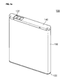
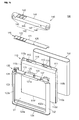
FIG. 1A illustrates an assembled perspective view of a battery pack according to an embodiment, andFIG. 2B illustrates an exploded perspective view; -
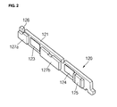
FIG. 2 illustrates a rear perspective view of a protective circuit module of a battery pack according to an embodiment; -
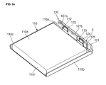
FIG. 3A illustrates a perspective view of a state in which a battery cell and a protective circuit module are electrically connected to each other in a battery pack according to an embodiment, andFIG. 3B illustrates an enlarged perspective view of aregion 3 ofFIG. 3A ; -
FIG. 4A illustrates a partially enlarged perspective view of a state in which a heat transfer member is attached to a cell tab and a positive temperature coefficient (PTC) device in a battery pack according to an embodiment, andFIG. 4B illustrates a sectional view taken along line 4-4 ofFIG. 4A ; -
FIG. 5 illustrates a sectional view of an attachment state of a heat transfer member according to another embodiment; -
FIG. 6 illustrates a sectional view of an attachment state of a heat transfer member according to another embodiments -
FIG. 7 illustrates a sectional view of an attachment state of a heat transfer member according to another embodiment; and -
FIG. 8 illustrates a sectional view of an attachment state of a heat transfer member according to another embodiment - Now, preferred embodiments of the present invention will be described in more detail with reference to the accompanying drawings, such that those skilled in the art can easily practice the present invention.
-
FIG. 1A illustrates an assembled perspective view of a battery pack according to an embodiment, andFIG. 2B illustrates an exploded perspective view. - Referring to
FIGS.1A and1B , abattery pack 100 according to an embodiment indudes abattery cell 110, aprotective circuit module 120, aframe case 130, acover 140, and alabel 150. - An electric charge is stored in or discharged from the
battery cell 110. Thebattery cell 110 is classified into a can type battery cell and a pouch type battery cell according to the material of a case surrounding an electrode assembly. The pouch type battery cell will be described in this embodiment as example. - The
battery cell 110 indudes an electrode assembly (not shown),cell tabs pouch case 111. The electrode assembly indudes a positive electrode, a negative electrode, and a separator disposed between the positive electrode and the negative electrode. Thecell tabs pouch case 111 receives the electrode assembly to expose thecell tabs insulating tapes electrode tabs pouch case 111 may be further disposed on thecell tabs - The
battery cell 110 may have atop surface 110a, a pair ofshort side surfaces long side surfaces bottom surface 110f. Thecircuit module 120 is disposed on thetop surface 110a. The pair ofshort side surfaces long side surfaces 110d and I 1 0e are connected to thetop surface 110a. Thebottom surface 110f faces thetop surface 110a and is connected to theside surfaces short side surfaces side surfaces top surface 110a of thebattery cell 110. The pair oflong side surfaces battery cell 110. - The
protective circuit module 120 is disposed on thetop surface 110a of thebattery cell 110 and electrically connected to thebattery cell 110 to control the charging and discharging of thebattery cell 110. Theprotective circuit module 120 may indude acircuit board 121,external terminals 122, internal terminals (not shown), a positive temperature coefficient (PTC) device (not shown), and acoupling groove 126. - The
external terminals 122 are disposed on a top surface of thecircuit board 121 to electrically connect thecircuit board 121 to an external electric device (not shown). Thecoupling groove 126 is defined in an outer circumference of a long side of thecircuit board 121 to physically couple theprotective circuit module 120 to theframe case 130. Theprotective circuit module 120 will be described below in detail. - The
frame case 130 surrounds thebattery cell 110 between thebattery cell 110 and theprotective module 120 and is physically coupled to theprotective circuit module 120. Theframe case 130 covers thetop surface 110a, thebottom surface 110f, and the pair of short side surfaces 110b and 110c of thebattery cell 110, respectively. Also, theframe case 130 exposes the pair oflong side surfaces battery cell 110 to the outside and covers lateral edge portions of the pair oflong side surfaces 110d and 11 due. Thus, theframe case 130 has a receiving space S1 of thebattery cell 110. - Specifically, the
frame case 130 indudesplanar parts planar parts top surface 110a, the pair of short side surfaces 110b and 110c, and thebottom surface 110f. The extension surfaces 131 a, 132a, 133a, and 134a are bent from end portions of theplanar parts long side surfaces battery cell 110 and extends toward thelong side surfaces battery cell 110 to cover the edge portions of the pair oflong side surfaces battery cell 110. - The
frame case 130 may indude asupport part 135 disposed on theplanar part 131, acoupling protrusion 136, and arib 137. - Each
support part 135 protrudes from an edge and a middle region of theplanar part 131 toward theprotective circuit module 120. Thesupport part 135 supports theprotective circuit module 120 when theprotective circuit module 120 is disposed above theplanar part 131 to provide a space between theplanar part 131 and theprotective circuit module 120. Thecell tabs - The
coupling protrusion 136 protrudes from thesupport part 135 corresponding to thecoupling groove 126 of theprotective circuit module 120 toward theprotective circuit module 120. Thecoupling protrusion 136 is inserted into thecoupling groove 126 to physically couple theprotective circuit module 120 to theframe case 130. - The
rib 137 protrudes from a lateral surface of thesupport part 135. Therib 137 is inserted into a rib coupling hole, which will be described later, of thecover 140 to physically couple theframe case 130 to thecover 140. - The
frame case 130 induding the above-described components may be integrally formed by an injection molding process. Theframe case 130 may be formed of one of polycarbonate (PC), polyethylene terephthalate glycol (PETG), polyethylene (PE), polypropylene (PP), and acronitrile-butadiene-styren (ABS). Thecover 140 is coupled to an upper portion of thebattery cell 110 to receive theprotective circuit module 120 in an inner space thereof. Thecover 140 indudes acover plate 141 and asidewall 162 extending from thecover plate 141 toward theprotective circuit module 120. - The
cover plate 141 may have a shape approximately similar to that of thecircuit board 121. An inner surface of thecover plate 141 facingly contacts the top surface of thecircuit board 121. Throughholes 143 are defined in a region of thecover plate 141 corresponding to theexternal terminals 122. The throughholes 143 expose theexternal terminals 122 to the outside to electrically connect thebattery pack 100 to an external electric device (not shown). - The
side wall 162 indude both endparts cover 140 andconnexion parts 146 connecting theend part 144 to theend part 145. Here, the bothend parts connection parts 146 are covered by thelabel 150. - Also, the
side wall 162 may include arib coupling hole 147 protrudingly defined from a region of therespective connection parts 146 corresponding to therib 137 of theframe case 130. Therib 137 of theframe case 130 is inserted into therib coupling hole 147 to physically couple theframe case 130 to thecover 140. - The
label 150 is surroundingly attached to the side surfaces 110b, 110c, 110d, and 110e of thebattery cell 110. Thelabel 150 covers portions of the bothend parts cover 140 and portions of theconnection parts 146. Thelabel 150 may improve coupling between thebattery cell 110, theframe case 130, and thecover 140. -
FIG. 2 illustrates a rear perspective view of a protective circuit module of a battery pack according to an embodiment. - Referring to
FIG. 2 , acircuit board 121 of aprotective circuit module 120 is mainly provided with an insulating layer. Thecircuit board 121 indudes acircuit 127a for detecting a charge voltage, a discharge voltage, and a current of abattery cell 110 and aswitch 127b for interrupting a current when an overcharge voltage, an overdischarge voltage, or an overcurrent condition is detected. -
Internal terminals circuit board 121 toward thebattery cell 110. Theinternal terminals battery cell 110 by direct welding. Here, theinternal terminal 123 and the cell tab may be electrically connected to a positive interconnection pattern (not shown), and theinternal terminal 124 and the cell tab may be electrically connected to a negative interconnection pattern (not shown) of theprotective circuit module 120 via a positive temperature coefficient (PTC)device 125. - The
PTC device 125 is mounted on thecircuit board 121. ThePTC device 125 is electrically connected to theinternal terminal 124 to interrupt a current when a temperature of thebattery cell 110 is beyond its allowable temperature, thereby preventing abnormal behavior due to overheating of the battery cell from occurring. Here, thePTC device 125 may be connected to theinternal terminal 123 instead of theinternal terminal 124. - Moreover, the
PTC device 125 has room temperature resistance of several hundred ohms and an operation temperature of about 75°C to about 120°C. ThePTC device 125 may indude a chip PTC thermister that can be surface mounted on thecircuit board 121, but is not limited thereto. - Although being described below in detail, a heat transfer member (not shown) is integrally attached to the cell tab, the
internal terminal 124, and thePTC device 125 to more quickly transfer heat generated in the cell tab and theinternal terminal 124 to thePTC device 125. -
FIG. 3A illustrates a perspective view of a state in which a battery cell and a protective circuit module are etectrica!!y connected to each other in a battery pack according to an embodiment, andFIG. 3B illustrates an enlarged perspective view of aregion 3 ofFIG. 3A . - Referring to
FIGS. 3A and3B , acell tab 112 of abattery cell 110 is connected to aninternal terminal 123 disposed on acircuit board 121 of aprotective circuit module 120. For example, thecell tab 112 may be connected to theinternal terminal 123 by ultrasonic welding, resistance welding, or laser welding. Also, acell tab 113 of thebattery cell 110 is connected to aninternal terminal 124 disposed on thecircuit board 121 of theprotective circuit module 120. Here, the connection process is performed using the same method as the above-described method. - Since a
PTC device 125 is electrically connected to theinternal terminal 124, and theinternal terminal 124 is electrically connected to thecell tab 113, thePTC device 125 is electrically connected to thecell tab 113. - Here, although not shown in
FIGS. 3A and3B , a planar part (seereference numeral 131 ofFIG. 1B ) of aframe case 130 is disposed between thebattery cell 110 and theprotective circuit module 120. Since theframe case 130 is formed of a resin having a low thermal conductivity, heat of thebattery cell 110 is not quickly transferred to thePTC device 125. Thus, when a temperature of thebattery cell 110 is beyond its allowable temperature, thePTC device 125 may not be quickly operated. -
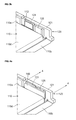
FIG. 4A illustrates a partially enlarged perspective view of a state in which a heat transfer member is attached to a cell tab and a positive temperature coefficient (PTC) device in a battery pack according to an embodiment, andFIG. 4B illustrates a sectional view taken along line 4-4 ofFIG. 4A Here, for convenience of comprehension, a frame case is not illustrated inFIG. 4A , and aplanar part 131 of the frame case is illustrated inFIG. 4B . - Referring to
FIGS. 4A and4B , acell tab 113 is connected to aninternal terminal 124, and aheat transfer member 160 having an integrated plate shape is attached to thecell tab 113 and thePTC device 125. When a current flows from thecell tab 113 to theinternal terminal 124 or from theinternal terminal 124 to thecell tab 113, a relative large contact resistance occurs in a contact region of thecell tab 113 and theinternal terminal 124. As a result, a large amount of heat is generated in the contact region. Specifically, when an overcurrent flows to generate heat in thebattery cell 110, thecell tab 113 and theinternal terminal 124 generate a large amount of heat. In this case, the heat generated in thecell tab 113 and theinternal terminal 124 is quickly and directly transferred to thePTC device 125 through theheat transfer member 160. Thus, although theplaner part 131 having a poor thermal conductivity is disposed between thebattery cell 110 and thePTC device 125, thePTC device 125 may be quickly operated because the heat generated in thecell tab 113 and theinternal terminal 124 is directly transferred to thePTC device 125 through theheat transfer member 160. That is, when the battery cell is overheated, the current is quickly interrupted. Thus, the stability and reliability of thebattery cell 110 are further improved. Moreover, one surface of theheat transfer member 160 may be attached or closely adhere to thecell tab 113, theinternal terminal 124, and thePTC device 125, and the other surface of theheat transfer member 160 may closely adhere to or be spaced from theplanar part 131 of the frame case. Theheat transfer member 160 may closely adhere to theplanar part 131 of the frame case to improve thermosensitive with respect to thebattery cell 110. - Referring to
FIG. 4B , thecircuit board 121 indudes an insulatinglayer 121a having a plate shape,interconnection patterns layer 121a, a conductive via 121e electrically connecting theinterconnection pattern 121c to theinterconnection pattern 121d, and a protection layers 121f and 121g covering theinterconnection patterns circuit board 121 is described as example, but is not limited thereto. For example, thecircuit board 121 may have a multi-layered structure. - The
internal terminal 124 is connected to theinterconnection pattern 121b. Also, thecell tab 113 is connected to theinternal terminal 124. ThePTC device 125 includesterminals PTC device material 125c. The oneside terminal 125a is connected to theinterconnection pattern 121 b, and theother side terminal 125b is connected to theinterconnection pattern 121c. Moreover, although not shown, theinterconnection pattern 121d may be electrically connected to an external terminal (e.g., a negative terminal). Theinternal terminal 124 may be integrally formed with theinterconnection pattern 121 b. Also, a plating layer is thickly coated on theinterconnection pattern 121 b to form theinternal terminal 124. - By the above-desaibed structure, the heat generated in the
cell tab 113 and theinternal terminal 124 may be transferred to thePTC device 125 through theinterconnection pattern 121b. However, since theinterconnection pattern 121 b has a thin thickness, a large amount of heat is not effectively transferred through theinterconnection pattern 121b when compared to theheat transfer member 160. Thus, theinterconnection pattern 121 b may have a relatively thick thickness to improve heat transfer efficiency through theinterconnection pattern 121 b. - The heat is transferred to the
PTC device 125 through three paths. Firstly, the heat is transferred to thePTC device 125 from thebattery cell 110 through theplanar part 131 of the frame case. Secondly, the heat is transferred to thePTC device 125 from thecell tab 113 and theinternal terminal 124 through theinterconnection pattern 121 b. Thirdly, the heat is transferred to thePTC device 125 from thecell tab 113 and theinternal terminal 124 through theheat transfer member 160. - Among these, when the heat is transferred through the
heat transfer member 160, heat transfer efficiency is the most excellent Next, when the heat is transferred through theinterconnection pattern 121b and theplanar part 131 of the frame case, heat transfer efficiency is excellent. - The
heat transfer member 160 may indude any member having electrical insulation and thermal conductivity. For example, theheat transfer member 160 may indude a thermally conductive acrylic foam tape induding ceramic particles, pressure sensitive acrylics, and flame retardants, but is not limited thereto. Also, theheat transfer member 160 may include a heatconductive part 161 and anadhesion part 162. That is, since the heatconductive part 161 does not have an adhesion property, thethin adhesion part 162 may be disposed on a surface of the heatconductive part 161. Theadhesion part 162 may be disposed on one surface or both side surfaces of the heatconductive part 161. That is, theheat transfer member 160 may have double-sided adhesive tape shape in which theadhesion parts 162 are disposed on the both side surfaces of the heatconductive part 161. If some technology is developed later on to allow the heatconductive part 161 to have an adhesion property, aseparate adhesion part 162 may not be disposed on the surface of the heatconducive part 161. - Referring to
FIG. 4B , theadhesion part 162 is disposed on only one surface of the heatconductive part 161 to provide theheat transfer member 160 attached to thecell tab 113 and thePTC device 125. - Additionally, an adiabatic
insulating part 163 by which heat is not well dissipated is further disposed on theheat transfer member 160. The adiabaticinsulating part 163 prevents heat from being dissipated to the outside after the heat is absorbed from thecell tab 113 into the heatconductive part 161. Thus, the heat absorbed through thecell tab 113 is stayed in the heatconductive part 161 for a long time to further improve thermal conductivity at thePTC device 125. The adiabaticinsulating part 163 may be formed of a material having thermal conductivity of about 0.03 W/m-k to about 0.06 W/m-k. For example, the adiabatic insulatingpart 163 may be formed of a material selected from the group consisting of a foam polystyrene thermal insulation material, an extruded foam polystyrene board, a thermal insulation material made of glass wool, a thermal insulation material made of rock wool, a foam polyethylene thermal insulation material, a polyurethane foam, a vermiculite, a perlite (pearl stone), and equivalents thereof, but is not limited thereto. In addition, when it is intended to effectively transfer the heat transferred from thebattery cell 110 through theplanar part 131 to theheat transfer member 160, the adiabatic insulatingpart 163 may be omitted. Also, the adiabatic insulatingpart 163 may be omitted in the following description. - The
heat transfer member 160 may indude the heatconductive part 161 and theadhesion part 162. One of commercial models of Korean company Samdo Ind.: SD-AT090, SD-AT040C, SD-AT045, STC-2400, and STC-2250 may be used as theheat transfer member 160. For example, physical properties of STC-2250 are as follows.Color Thickness Tensile Strength Elongation Initial Adhesive Strength Normal Adhesive Strength *HRC Heat Conductivity mm kg/cm2 % g/cm g/cm °C W/m-K White 025 12.4 260 375 650 ≥110 0.8 * HRC: Heat Creep Resistance - In Table, the initial adhesive strength was measured by a 180-degree pulling separation method based on KSA 1529 (Korean industrial standards).
- Wait time: 30 minutes
- Measurement Speed: 300 mm/min
- Measurement Width: 10 mm
- The normal adhesive strength was measured by the same method except that the wait time was one day (24 hours).
- The HCR was measured by attaching a 25 mm x 25 mm sample to a SUS (stainless steel plane), suspending a 500-g weight from the sample, and increasing the temperature at a rate of 10°C/20 minutes. Then, when the weight falls down, the temperature or slipping distance was measured.
- As shown above, the
heat transfer member 160 has high heat conductivity (K>0.8 W/m-K), low heat resistance, uniform heat distribution property (temperature uniformity), and high mechanical strength (shear, tensile strength) at high temperatures. In addition, the adhesive strength of theheat transfer member 160 may be well maintained at high temperatures. - Therefore, when the
cell tab 113 and theinternal terminals 124 are overheated due to an overcurrent, heat may be quickly transferred to thePTC device 125 through theheat transfer member 160 of which the mechanical strength and adhesive strength are not reduced at high temperatures. That is, theheat transfer member 160 may be applied to the battery pack according to an embodiment. -
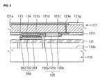
FIG. 5 illustrates a sectional view of an attachment state of a heat transfer member according to another embodiment. - Referring to
Fig. 5 , according to the current embodiment, aheat transfer member 260 may be attached to only acell tab 113. That is, theheat transfer member 260 constituted by anadhesion part 262, a heatconductive part 261, and an adiabaticinsulating part 263 is attached to only thecell tab 113. - In detail, the
adhesion part 262 is attached to only thecell tab 113, and the heatconductive part 261 is disposed on the surface of theadhesion part 262. The adiabaticinsulating part 263 is disposed on the heatconductive part 261. Therefore, in practical, although theheat transfer member 260 absorbs heat from thecell tab 113, the heat is not well dissipated to the outside. As a result heat generated at thecell tab 113 is transferred to aPTC device 125 mainly through aninterconnection pattern 121b. That is, since theheat transfer member 260 does not directly connect thecell tab 113 and thePTC device 125 at the same time, heat accumulated in theheat transfer member 260 is transferred to thePTC device 125 through theinterconnection pattern 121 b that electrically connects thecell tab 113 to thePTC device 125. -
FIG. 6 illustrates a sectional view of an attachment state of a heat transfer member according to another embodiment. - Referring to
Fig. 6 , according to the current embodiment, aheat transfer member 360 completely covers acell tab 113, aninternal terminal 124 and aPTC device 125. In addition, theheat transfer member 360 covers a portion of acircuit board 121 corresponding to an outer circumference of thecell tab 113, theinternal terminal 124 and thePTC device 125. - In more detail, an
adhesion part 362 is attached to thecell tab 113, theinternal terminal 124 and thePTC device 125, and the outer circumference of thecircuit board 121 thereof. A heatconductive part 361 is disposed on theadhesion part 362. An adiabatic insulatingpart 363 is disposed on the heatconductive part 361. In this way, the outer circumference of thecircuit board 121, as well as the surfaces of thecell tab 113, theinternal terminal 124 and thePTC device 125, is completely covered with theadhesion part 362, the heatconductive part 361, and the adiabatic insulatingpart 363. - Therefore, heat transfer from the
cell tab 113 to thePTC device 125 may be efficiency performed through the heatconducive part 361, and heat is not dissipated from the heatconductive part 361 to the outside area owning to the adiabatic insulatingpart 363. Therefore, thePTC device 125 may be sensitively operated in response to heat generated from thecell tab 113. When the surfaces of thecell tab 113 and thePTC device 125 are substantially covered with theheat transfer member 360, the heat transfer efficiency of theheat transfer member 360 may be optimal. -
FIG. 7 illustrates a sectional view of an attachment state of a heat transfer member according to another embodiment - Referring to
FIG. 7 , aheat transfer member 460 completely covers only acell tab 113 and aninternal terminal 124. Also, theheat transfer member 460 covers a portion of acircuit board 121, i.e., an outer circumference of thecell tab 113 and theinternal terminal 124. - In detail, an
adhesion part 462 is attached to thecell tab 113, theinternal terminal 124 and the circuit board corresponding to the outer circumference of thecell tab 113 andinternal terminal 124. Also, a heatconductive part 461 is disposed on theadhesion part 462. An adiabatic insulatingpart 463 is disposed on the heatconductive part 461. Thus, heat generated in thecell tab 113 is absorbed through the heatconductive part 461 and is not dissipated by the adiabatic insulatingpart 463 to the outside. Therefore, the heat generated from thecell tab 113 is mainly quickly transferred to aPTC device 125 through aninterconnection pattern 121b. -
FIG. 8 illustrates a sectional view of an attachment state of a heat transfer member according to another embodiment. - Referring to
FIG. 8 , aheat transfer member 560 covers acell tab 113, aninternal terminal 124 and aninterconnection pattern 121 b disposed outside theinternal terminal 124. - In detail, a protection layers 121f does not cover the
interconnection pattern 121b corresponding to the outside of theinternal terminal 124. Therefore, theinterconnection pattern 121 b is exposed to outside. Anadhesion part 562 of theheat transfer member 560 is attached to thecell tab 113, theinternal terminal 124 and theinterconnection pattern 121b. Also, a heatconductive part 561 is disposed on theadhesion part 562. An adiabatic insulatingpart 563 is disposed on the heatconductive part 561. - Thus, heat generated in the
cell tab 113 is rapidly transferred to theinterconnection pattern 121 b through theheat transfer member 560, and the heat is rapidly transferred to aPTC device 125 through aninterconnection pattern 121 b.
Claims (12)
- A battery pack (100), comprising:a battery cell (110) induding a cell tab (113), anda protective circuit module (120) induding an internal terminal (124) coupled to the cell tab (113) anda positive temperature coefficient (PTC) device (125) coupled to the internal terminal (124),characterized in thatthe protective circuit module (120) further indudes a heat transfer member (160) consisting in parts or totally of a thermal but not electrically conductive material and being coupled to the cell tab (113) and the PTC device (125), wherein the heat transfer member (160) is covered by an adiabatic insulating part (163).
- The battery pack of claim 1, wherein the heat transfer member (160) is a thermally conductive tape.
- The battery pack of claim 2, wherein the heat transfer member (160) is a thermally conductive adhesive tape.
- The battery pack of any of daims 2 or 3, wherein the heat transfer member (160) comprises ceramic particles, pressure sensitive acrylics, and/or a flame retardant
- The battery pack of any of daims 2 through 4, wherein the heat transfer member (160) comprises:a heat conductive layer,a first adhesive layer disposed between the heat conductive layer and the cell tab (113); anda second adhesive layer disposed on the heat conductive layer on a side opposite the first adhesive layer.
- The battery pack of any of the preceding claims, wherein the internal terminal (124) extends beyond the edges of the cell tab (113), and the heat transfer member (460) contacts the cell tab (113), the internal terminal (124), and a protection layer (121f) of the protective circuit module (120).
- The battery pack of any of daims 1 through 5, wherein the heat transfer member (360) contacts the cell tab (113), the internal terminal (124), the PTC device (125), and a protection layer (121f) of the protective circuit module (120).
- The battery pack of any of daims 1 through 5, wherein the heat transfer member (560) contacts an interconnection pattern (121 b) of the protective circuit module (120) adjacent to the internal terminal (124), the cell tab (113) and the PTC device (125).
- The battery pack of any of claims 1 through 5, wherein the internal terminal (124) extends beyond at least an edge of the cell tab (113), and the heat transfer member (160) contacts the cell tab (113), the internal terminal (124), the PTC device (125), and an interconnection pattern (121b) of the protective circuit module (120) adjacent to the cell tab (113), the internal terminal (124), and the PTC device (125).
- The battery pack of any of the preceding claims, wherein the battery pack (100) further indudes a frame case (130) being formed of a resin and surrounding the battery cell (110).
- The battery pack of claim 10, wherein the frame case (130) is being coupled to the protective circuit module (120) such that there remains a space between the protective circuit board (120) and the frame case (130), wherein the internal terminal (124), the cell tab (113), the PTC device (125) and the heat transfer member (160) are provided within the space.
- The battery pack of any of the preceding claims, wherein the protective circuit module (120) transfers heat from the battery cell (110) to the PTC device (125).
Applications Claiming Priority (1)
| Application Number | Priority Date | Filing Date | Title |
|---|---|---|---|
| US27206309P | 2009-08-12 | 2009-08-12 |
Publications (2)
| Publication Number | Publication Date |
|---|---|
| EP2284931A1 EP2284931A1 (en) | 2011-02-16 |
| EP2284931B1 true EP2284931B1 (en) | 2012-01-04 |
Family
ID=42984643
Family Applications (1)
| Application Number | Title | Priority Date | Filing Date |
|---|---|---|---|
| EP20100172351 Active EP2284931B1 (en) | 2009-08-12 | 2010-08-10 | Battery pack |
Country Status (6)
| Country | Link |
|---|---|
| US (1) | US8916278B2 (en) |
| EP (1) | EP2284931B1 (en) |
| JP (1) | JP5449085B2 (en) |
| KR (1) | KR101146455B1 (en) |
| CN (1) | CN101997093B (en) |
| AT (1) | ATE540442T1 (en) |
Families Citing this family (42)
| Publication number | Priority date | Publication date | Assignee | Title |
|---|---|---|---|---|
| US9350001B2 (en) * | 2010-07-09 | 2016-05-24 | Samsung Sdi Co., Ltd. | Battery pack for a lithium polymer Battery |
| KR20130062197A (en) * | 2011-12-02 | 2013-06-12 | 삼성에스디아이 주식회사 | Battery pack and method of manufacturing thereof |
| KR102028172B1 (en) * | 2013-06-25 | 2019-10-02 | 삼성에스디아이 주식회사 | Battery pack |
| US20150044511A1 (en) * | 2013-08-08 | 2015-02-12 | Samsung Sdi Co., Ltd. | Battery pack |
| US20150064518A1 (en) * | 2013-08-29 | 2015-03-05 | Fuzetec Technology Co., Ltd. | Over-current protection device and battery assembly |
| KR102030110B1 (en) | 2013-08-30 | 2019-11-08 | 삼성에스디아이 주식회사 | Secondary battery |
| KR101673972B1 (en) * | 2014-02-17 | 2016-11-08 | 주식회사 엘지화학 | Battery pack |
| CN104953642A (en) * | 2015-03-27 | 2015-09-30 | 广东欧珀移动通信有限公司 | Rechargeable battery pack and terminal device |
| CN105605413B (en) * | 2016-01-07 | 2019-05-28 | 惠生(南通)重工有限公司 | A kind of insulating treatment method of SPB storage tank |
| US10103415B2 (en) * | 2016-02-03 | 2018-10-16 | GM Global Technology Operations LLC | Battery pack with intracell heat conducting members |
| CN105703037B (en) * | 2016-04-08 | 2018-08-17 | 努比亚技术有限公司 | A kind of battery heat removal system and method |
| EP3316384B1 (en) * | 2016-10-25 | 2019-02-20 | Samsung SDI Co., Ltd. | Battery module with a fixing for a temperature sensitive element |
| WO2018080033A1 (en) * | 2016-10-25 | 2018-05-03 | 삼성에스디아이 주식회사 | Battery module having fixing structure for temperature sensor |
| CN109478691B (en) | 2017-01-12 | 2021-12-21 | 株式会社Lg化学 | Secondary battery |
| KR102431281B1 (en) | 2017-01-12 | 2022-08-11 | 주식회사 엘지에너지솔루션 | Positive electrode and secondary battery comprising the same |
| KR102101008B1 (en) | 2017-01-12 | 2020-04-14 | 주식회사 엘지화학 | Secondary battery |
| KR102357835B1 (en) * | 2017-01-26 | 2022-02-04 | 삼성에스디아이 주식회사 | Battery pack |
| KR102179687B1 (en) * | 2017-05-29 | 2020-11-17 | 주식회사 엘지화학 | Battery pack and method for manufacturing the same |
| KR102195728B1 (en) * | 2017-12-11 | 2020-12-28 | 삼성에스디아이 주식회사 | Battery Pack |
| KR102353917B1 (en) | 2018-01-04 | 2022-01-19 | 주식회사 엘지에너지솔루션 | Battery Module Having Heat Conduction Pad |
| KR102270269B1 (en) | 2018-01-17 | 2021-06-28 | 주식회사 엘지에너지솔루션 | Battery module housing having a reusable, recyclable or reworkable adhesive structure and Battery module the same |
| CN110071255B (en) * | 2018-01-23 | 2022-09-09 | 宁德新能源科技有限公司 | Cells and Batteries |
| EP3700004A4 (en) * | 2018-06-14 | 2021-03-10 | Lg Chem, Ltd. | APPARATUS AND METHOD FOR MEASURING THE BATTERY TEMPERATURE |
| KR102549437B1 (en) * | 2018-11-30 | 2023-06-28 | 주식회사 엘지에너지솔루션 | Electrode assembly and secondary battery including the same |
| JP7136708B2 (en) * | 2019-01-16 | 2022-09-13 | 本田技研工業株式会社 | All-solid battery cell |
| CN111477966B (en) * | 2019-01-23 | 2021-11-23 | 北京小米移动软件有限公司 | Terminal battery protection board, terminal battery and terminal |
| KR102480959B1 (en) | 2019-04-17 | 2022-12-23 | 주식회사 엘지에너지솔루션 | secondary battery and battery module including the same |
| CN110001453B (en) * | 2019-04-19 | 2019-12-03 | 宿州速果信息科技有限公司 | A kind of new energy car battery packet temperature protection equipment |
| CN110176563A (en) * | 2019-05-13 | 2019-08-27 | 北京长城华冠汽车科技股份有限公司 | Car battery and its battery core support component |
| DE102019113914A1 (en) * | 2019-05-24 | 2020-11-26 | Bayerische Motoren Werke Aktiengesellschaft | Lid assembly for a cell housing of a prismatic battery cell with connection contacts for a heating device, battery cell and high-voltage battery |
| MX2022007435A (en) * | 2020-01-07 | 2022-07-19 | Aspen Aerogels Inc | BATTERY THERMAL MANAGEMENT ELEMENT. |
| KR102812829B1 (en) * | 2020-03-05 | 2025-05-23 | 주식회사 엘지에너지솔루션 | Battery pack with structure of improved convenience for carrying and assembling and improved safety |
| CN114287172A (en) * | 2020-03-27 | 2022-04-05 | 鹏鼎控股(深圳)股份有限公司 | Cover film, circuit board, and manufacturing method |
| WO2021245780A1 (en) * | 2020-06-02 | 2021-12-09 | ソニーグループ株式会社 | Electronic instrument |
| KR102755060B1 (en) * | 2020-10-29 | 2025-01-20 | 주식회사 엘지에너지솔루션 | Battery pack including a protection circuit module heat radiation structure using heat radiation tape |
| KR20220158538A (en) * | 2021-05-24 | 2022-12-01 | 삼성에스디아이 주식회사 | Battery pack |
| CN117157806A (en) * | 2021-07-02 | 2023-12-01 | 亚斯朋空气凝胶公司 | System and method for mitigating heat transfer in battery-based energy storage systems |
| EP4539209A3 (en) | 2021-09-27 | 2025-07-30 | QuantumScape Battery, Inc. | Electrochemical stack and method of assembly thereof |
| US20230139302A1 (en) * | 2021-09-30 | 2023-05-04 | Inventus Power, Inc. | Thermal management for a conformal wearable battery |
| WO2024123295A1 (en) * | 2022-12-06 | 2024-06-13 | Nero Endüstri̇ Savunma Sanayi̇ Anoni̇m Şi̇rketi̇ | Thermal wire system for battery boxes |
| KR20250082668A (en) * | 2023-11-30 | 2025-06-09 | 삼성에스디아이 주식회사 | Apparatus for heating battery cell and battery module |
| CN222654116U (en) * | 2024-04-03 | 2025-03-21 | 惠州亿纬锂能股份有限公司 | Battery assembly structure and battery module |
Family Cites Families (14)
| Publication number | Priority date | Publication date | Assignee | Title |
|---|---|---|---|---|
| JP3203623B2 (en) * | 1992-03-06 | 2001-08-27 | ソニー株式会社 | Organic electrolyte battery |
| AU5574396A (en) * | 1995-05-04 | 1996-11-21 | Intel Corporation | Printed circuit board with selectable routing configuration |
| JP4904614B2 (en) * | 2000-06-22 | 2012-03-28 | パナソニック株式会社 | Battery pack and manufacturing method thereof |
| JP2002313295A (en) * | 2001-04-11 | 2002-10-25 | Gs-Melcotec Co Ltd | Rechargeable battery pack |
| JP4629952B2 (en) | 2002-02-13 | 2011-02-09 | パナソニック株式会社 | Manufacturing method of secondary battery |
| DE10214366B4 (en) | 2002-03-30 | 2017-03-16 | Robert Bosch Gmbh | measuring arrangement |
| KR100502354B1 (en) | 2003-06-20 | 2005-07-21 | 삼성에스디아이 주식회사 | Pouched-type lithium secondary battery |
| US7456614B2 (en) * | 2003-10-27 | 2008-11-25 | Sony Corporation | Battery pack |
| KR100645256B1 (en) * | 2004-01-28 | 2006-11-14 | 주식회사 엘지화학 | Secondary battery of assemble-type structure |
| JP4766842B2 (en) | 2004-04-30 | 2011-09-07 | 三洋電機株式会社 | Pack battery |
| KR100624950B1 (en) * | 2004-10-18 | 2006-09-15 | 삼성에스디아이 주식회사 | Battery exterior material with heat dissipation layer and lithium polymer battery using same |
| KR100760784B1 (en) | 2006-07-04 | 2007-09-20 | 삼성에스디아이 주식회사 | Secondary battery protection circuit module and battery pack using same |
| KR100778993B1 (en) | 2006-08-31 | 2007-11-22 | 삼성에스디아이 주식회사 | Secondary battery with side cover |
| KR100851963B1 (en) | 2008-02-22 | 2008-08-12 | 주식회사 퓨처라인 | Secondary Battery with Protection Circuit Module with Fetish Element |
-
2010
- 2010-07-21 US US12/840,462 patent/US8916278B2/en active Active
- 2010-07-23 KR KR1020100071339A patent/KR101146455B1/en active Active
- 2010-08-10 AT AT10172351T patent/ATE540442T1/en active
- 2010-08-10 EP EP20100172351 patent/EP2284931B1/en active Active
- 2010-08-10 JP JP2010179672A patent/JP5449085B2/en active Active
- 2010-08-12 CN CN201010253696.0A patent/CN101997093B/en active Active
Also Published As
| Publication number | Publication date |
|---|---|
| ATE540442T1 (en) | 2012-01-15 |
| JP2011040387A (en) | 2011-02-24 |
| KR20110016821A (en) | 2011-02-18 |
| CN101997093A (en) | 2011-03-30 |
| US8916278B2 (en) | 2014-12-23 |
| EP2284931A1 (en) | 2011-02-16 |
| JP5449085B2 (en) | 2014-03-19 |
| CN101997093B (en) | 2014-12-10 |
| KR101146455B1 (en) | 2012-05-18 |
| US20110039134A1 (en) | 2011-02-17 |
Similar Documents
| Publication | Publication Date | Title |
|---|---|---|
| EP2284931B1 (en) | Battery pack | |
| EP2058878B1 (en) | Battery pack and electronic device using the same | |
| US9219266B2 (en) | Secondary battery pack of novel structure | |
| KR101431720B1 (en) | Switching Board of Novel Structure, and Battery Module Containing the Same | |
| KR101192042B1 (en) | Battery Pack | |
| EP2835846A1 (en) | Battery pack | |
| EP2413400A2 (en) | Secondary battery | |
| KR100824875B1 (en) | Battery packs and manufacturing methods thereof | |
| CN101400209B (en) | Protective circuit board and battery pack using the same | |
| KR20130018477A (en) | Secondary battery pack of novel structure | |
| EP2284926A2 (en) | Secondary battery | |
| KR20150065280A (en) | Battery pack | |
| CN103840228A (en) | Battery pack | |
| EP2706588B1 (en) | Lead tab, battery pack having the lead tab and method of manufacturing the lead tab | |
| US8945734B2 (en) | Secondary battery including protection circuit module | |
| US20110076520A1 (en) | Secondary battery | |
| US20140349141A1 (en) | Battery pack | |
| WO2025084232A1 (en) | Electronic apparatus, battery pack, and method for manufacturing battery pack | |
| JP2014102989A (en) | Battery pack |
Legal Events
| Date | Code | Title | Description |
|---|---|---|---|
| PUAI | Public reference made under article 153(3) epc to a published international application that has entered the european phase |
Free format text: ORIGINAL CODE: 0009012 |
|
| 17P | Request for examination filed |
Effective date: 20100810 |
|
| AK | Designated contracting states |
Kind code of ref document: A1 Designated state(s): AL AT BE BG CH CY CZ DE DK EE ES FI FR GB GR HR HU IE IS IT LI LT LU LV MC MK MT NL NO PL PT RO SE SI SK SM TR |
|
| AX | Request for extension of the european patent |
Extension state: BA ME RS |
|
| GRAP | Despatch of communication of intention to grant a patent |
Free format text: ORIGINAL CODE: EPIDOSNIGR1 |
|
| RIC1 | Information provided on ipc code assigned before grant |
Ipc: H01M 6/50 20060101ALI20110628BHEP Ipc: H01M 2/34 20060101ALI20110628BHEP Ipc: H01M 2/22 20060101AFI20110628BHEP Ipc: H01M 10/50 20060101ALI20110628BHEP |
|
| GRAS | Grant fee paid |
Free format text: ORIGINAL CODE: EPIDOSNIGR3 |
|
| GRAA | (expected) grant |
Free format text: ORIGINAL CODE: 0009210 |
|
| AK | Designated contracting states |
Kind code of ref document: B1 Designated state(s): AL AT BE BG CH CY CZ DE DK EE ES FI FR GB GR HR HU IE IS IT LI LT LU LV MC MK MT NL NO PL PT RO SE SI SK SM TR |
|
| REG | Reference to a national code |
Ref country code: GB Ref legal event code: FG4D |
|
| REG | Reference to a national code |
Ref country code: CH Ref legal event code: EP |
|
| REG | Reference to a national code |
Ref country code: AT Ref legal event code: REF Ref document number: 540442 Country of ref document: AT Kind code of ref document: T Effective date: 20120115 |
|
| REG | Reference to a national code |
Ref country code: IE Ref legal event code: FG4D |
|
| REG | Reference to a national code |
Ref country code: DE Ref legal event code: R096 Ref document number: 602010000626 Country of ref document: DE Effective date: 20120301 |
|
| REG | Reference to a national code |
Ref country code: NL Ref legal event code: VDEP Effective date: 20120104 |
|
| PG25 | Lapsed in a contracting state [announced via postgrant information from national office to epo] |
Ref country code: SI Free format text: LAPSE BECAUSE OF FAILURE TO SUBMIT A TRANSLATION OF THE DESCRIPTION OR TO PAY THE FEE WITHIN THE PRESCRIBED TIME-LIMIT Effective date: 20120104 |
|
| LTIE | Lt: invalidation of european patent or patent extension |
Effective date: 20120104 |
|
| PG25 | Lapsed in a contracting state [announced via postgrant information from national office to epo] |
Ref country code: IS Free format text: LAPSE BECAUSE OF FAILURE TO SUBMIT A TRANSLATION OF THE DESCRIPTION OR TO PAY THE FEE WITHIN THE PRESCRIBED TIME-LIMIT Effective date: 20120504 Ref country code: NL Free format text: LAPSE BECAUSE OF FAILURE TO SUBMIT A TRANSLATION OF THE DESCRIPTION OR TO PAY THE FEE WITHIN THE PRESCRIBED TIME-LIMIT Effective date: 20120104 Ref country code: BG Free format text: LAPSE BECAUSE OF FAILURE TO SUBMIT A TRANSLATION OF THE DESCRIPTION OR TO PAY THE FEE WITHIN THE PRESCRIBED TIME-LIMIT Effective date: 20120404 Ref country code: BE Free format text: LAPSE BECAUSE OF FAILURE TO SUBMIT A TRANSLATION OF THE DESCRIPTION OR TO PAY THE FEE WITHIN THE PRESCRIBED TIME-LIMIT Effective date: 20120104 Ref country code: NO Free format text: LAPSE BECAUSE OF FAILURE TO SUBMIT A TRANSLATION OF THE DESCRIPTION OR TO PAY THE FEE WITHIN THE PRESCRIBED TIME-LIMIT Effective date: 20120404 Ref country code: HR Free format text: LAPSE BECAUSE OF FAILURE TO SUBMIT A TRANSLATION OF THE DESCRIPTION OR TO PAY THE FEE WITHIN THE PRESCRIBED TIME-LIMIT Effective date: 20120104 Ref country code: LT Free format text: LAPSE BECAUSE OF FAILURE TO SUBMIT A TRANSLATION OF THE DESCRIPTION OR TO PAY THE FEE WITHIN THE PRESCRIBED TIME-LIMIT Effective date: 20120104 |
|
| PG25 | Lapsed in a contracting state [announced via postgrant information from national office to epo] |
Ref country code: PL Free format text: LAPSE BECAUSE OF FAILURE TO SUBMIT A TRANSLATION OF THE DESCRIPTION OR TO PAY THE FEE WITHIN THE PRESCRIBED TIME-LIMIT Effective date: 20120104 Ref country code: LV Free format text: LAPSE BECAUSE OF FAILURE TO SUBMIT A TRANSLATION OF THE DESCRIPTION OR TO PAY THE FEE WITHIN THE PRESCRIBED TIME-LIMIT Effective date: 20120104 Ref country code: GR Free format text: LAPSE BECAUSE OF FAILURE TO SUBMIT A TRANSLATION OF THE DESCRIPTION OR TO PAY THE FEE WITHIN THE PRESCRIBED TIME-LIMIT Effective date: 20120405 Ref country code: FI Free format text: LAPSE BECAUSE OF FAILURE TO SUBMIT A TRANSLATION OF THE DESCRIPTION OR TO PAY THE FEE WITHIN THE PRESCRIBED TIME-LIMIT Effective date: 20120104 Ref country code: PT Free format text: LAPSE BECAUSE OF FAILURE TO SUBMIT A TRANSLATION OF THE DESCRIPTION OR TO PAY THE FEE WITHIN THE PRESCRIBED TIME-LIMIT Effective date: 20120504 |
|
| REG | Reference to a national code |
Ref country code: AT Ref legal event code: MK05 Ref document number: 540442 Country of ref document: AT Kind code of ref document: T Effective date: 20120104 |
|
| PG25 | Lapsed in a contracting state [announced via postgrant information from national office to epo] |
Ref country code: CY Free format text: LAPSE BECAUSE OF FAILURE TO SUBMIT A TRANSLATION OF THE DESCRIPTION OR TO PAY THE FEE WITHIN THE PRESCRIBED TIME-LIMIT Effective date: 20120104 |
|
| PG25 | Lapsed in a contracting state [announced via postgrant information from national office to epo] |
Ref country code: EE Free format text: LAPSE BECAUSE OF FAILURE TO SUBMIT A TRANSLATION OF THE DESCRIPTION OR TO PAY THE FEE WITHIN THE PRESCRIBED TIME-LIMIT Effective date: 20120104 Ref country code: CZ Free format text: LAPSE BECAUSE OF FAILURE TO SUBMIT A TRANSLATION OF THE DESCRIPTION OR TO PAY THE FEE WITHIN THE PRESCRIBED TIME-LIMIT Effective date: 20120104 Ref country code: RO Free format text: LAPSE BECAUSE OF FAILURE TO SUBMIT A TRANSLATION OF THE DESCRIPTION OR TO PAY THE FEE WITHIN THE PRESCRIBED TIME-LIMIT Effective date: 20120104 Ref country code: SE Free format text: LAPSE BECAUSE OF FAILURE TO SUBMIT A TRANSLATION OF THE DESCRIPTION OR TO PAY THE FEE WITHIN THE PRESCRIBED TIME-LIMIT Effective date: 20120104 Ref country code: DK Free format text: LAPSE BECAUSE OF FAILURE TO SUBMIT A TRANSLATION OF THE DESCRIPTION OR TO PAY THE FEE WITHIN THE PRESCRIBED TIME-LIMIT Effective date: 20120104 |
|
| PLBE | No opposition filed within time limit |
Free format text: ORIGINAL CODE: 0009261 |
|
| STAA | Information on the status of an ep patent application or granted ep patent |
Free format text: STATUS: NO OPPOSITION FILED WITHIN TIME LIMIT |
|
| PG25 | Lapsed in a contracting state [announced via postgrant information from national office to epo] |
Ref country code: SK Free format text: LAPSE BECAUSE OF FAILURE TO SUBMIT A TRANSLATION OF THE DESCRIPTION OR TO PAY THE FEE WITHIN THE PRESCRIBED TIME-LIMIT Effective date: 20120104 Ref country code: IT Free format text: LAPSE BECAUSE OF FAILURE TO SUBMIT A TRANSLATION OF THE DESCRIPTION OR TO PAY THE FEE WITHIN THE PRESCRIBED TIME-LIMIT Effective date: 20120104 |
|
| 26N | No opposition filed |
Effective date: 20121005 |
|
| PG25 | Lapsed in a contracting state [announced via postgrant information from national office to epo] |
Ref country code: AT Free format text: LAPSE BECAUSE OF FAILURE TO SUBMIT A TRANSLATION OF THE DESCRIPTION OR TO PAY THE FEE WITHIN THE PRESCRIBED TIME-LIMIT Effective date: 20120104 |
|
| REG | Reference to a national code |
Ref country code: DE Ref legal event code: R097 Ref document number: 602010000626 Country of ref document: DE Effective date: 20121005 |
|
| PG25 | Lapsed in a contracting state [announced via postgrant information from national office to epo] |
Ref country code: MC Free format text: LAPSE BECAUSE OF NON-PAYMENT OF DUE FEES Effective date: 20120831 |
|
| PG25 | Lapsed in a contracting state [announced via postgrant information from national office to epo] |
Ref country code: ES Free format text: LAPSE BECAUSE OF FAILURE TO SUBMIT A TRANSLATION OF THE DESCRIPTION OR TO PAY THE FEE WITHIN THE PRESCRIBED TIME-LIMIT Effective date: 20120415 |
|
| REG | Reference to a national code |
Ref country code: IE Ref legal event code: MM4A |
|
| PG25 | Lapsed in a contracting state [announced via postgrant information from national office to epo] |
Ref country code: IE Free format text: LAPSE BECAUSE OF NON-PAYMENT OF DUE FEES Effective date: 20120810 |
|
| PG25 | Lapsed in a contracting state [announced via postgrant information from national office to epo] |
Ref country code: AL Free format text: LAPSE BECAUSE OF FAILURE TO SUBMIT A TRANSLATION OF THE DESCRIPTION OR TO PAY THE FEE WITHIN THE PRESCRIBED TIME-LIMIT Effective date: 20120104 Ref country code: MT Free format text: LAPSE BECAUSE OF FAILURE TO SUBMIT A TRANSLATION OF THE DESCRIPTION OR TO PAY THE FEE WITHIN THE PRESCRIBED TIME-LIMIT Effective date: 20120104 |
|
| PG25 | Lapsed in a contracting state [announced via postgrant information from national office to epo] |
Ref country code: TR Free format text: LAPSE BECAUSE OF FAILURE TO SUBMIT A TRANSLATION OF THE DESCRIPTION OR TO PAY THE FEE WITHIN THE PRESCRIBED TIME-LIMIT Effective date: 20120104 |
|
| PG25 | Lapsed in a contracting state [announced via postgrant information from national office to epo] |
Ref country code: LU Free format text: LAPSE BECAUSE OF NON-PAYMENT OF DUE FEES Effective date: 20120810 Ref country code: SM Free format text: LAPSE BECAUSE OF FAILURE TO SUBMIT A TRANSLATION OF THE DESCRIPTION OR TO PAY THE FEE WITHIN THE PRESCRIBED TIME-LIMIT Effective date: 20120104 |
|
| PG25 | Lapsed in a contracting state [announced via postgrant information from national office to epo] |
Ref country code: HU Free format text: LAPSE BECAUSE OF FAILURE TO SUBMIT A TRANSLATION OF THE DESCRIPTION OR TO PAY THE FEE WITHIN THE PRESCRIBED TIME-LIMIT Effective date: 20100810 |
|
| REG | Reference to a national code |
Ref country code: CH Ref legal event code: PL |
|
| PG25 | Lapsed in a contracting state [announced via postgrant information from national office to epo] |
Ref country code: CH Free format text: LAPSE BECAUSE OF NON-PAYMENT OF DUE FEES Effective date: 20140831 Ref country code: LI Free format text: LAPSE BECAUSE OF NON-PAYMENT OF DUE FEES Effective date: 20140831 |
|
| PG25 | Lapsed in a contracting state [announced via postgrant information from national office to epo] |
Ref country code: MK Free format text: LAPSE BECAUSE OF FAILURE TO SUBMIT A TRANSLATION OF THE DESCRIPTION OR TO PAY THE FEE WITHIN THE PRESCRIBED TIME-LIMIT Effective date: 20120104 |
|
| REG | Reference to a national code |
Ref country code: FR Ref legal event code: PLFP Year of fee payment: 7 |
|
| REG | Reference to a national code |
Ref country code: FR Ref legal event code: PLFP Year of fee payment: 8 |
|
| REG | Reference to a national code |
Ref country code: FR Ref legal event code: PLFP Year of fee payment: 9 |
|
| REG | Reference to a national code |
Ref country code: DE Ref legal event code: R079 Ref document number: 602010000626 Country of ref document: DE Free format text: PREVIOUS MAIN CLASS: H01M0002220000 Ipc: H01M0050528000 |
|
| P01 | Opt-out of the competence of the unified patent court (upc) registered |
Effective date: 20230528 |
|
| PGFP | Annual fee paid to national office [announced via postgrant information from national office to epo] |
Ref country code: DE Payment date: 20250805 Year of fee payment: 16 |
|
| PGFP | Annual fee paid to national office [announced via postgrant information from national office to epo] |
Ref country code: GB Payment date: 20250731 Year of fee payment: 16 |
|
| PGFP | Annual fee paid to national office [announced via postgrant information from national office to epo] |
Ref country code: FR Payment date: 20250808 Year of fee payment: 16 |