EP2284422A1 - Piston for engine having stable behavior of piston ring - Google Patents
Piston for engine having stable behavior of piston ring Download PDFInfo
- Publication number
- EP2284422A1 EP2284422A1 EP10008169A EP10008169A EP2284422A1 EP 2284422 A1 EP2284422 A1 EP 2284422A1 EP 10008169 A EP10008169 A EP 10008169A EP 10008169 A EP10008169 A EP 10008169A EP 2284422 A1 EP2284422 A1 EP 2284422A1
- Authority
- EP
- European Patent Office
- Prior art keywords
- ring
- piston
- gap
- shaped groove
- engine
- Prior art date
- Legal status (The legal status is an assumption and is not a legal conclusion. Google has not performed a legal analysis and makes no representation as to the accuracy of the status listed.)
- Granted
Links
Images




Classifications
-
- F—MECHANICAL ENGINEERING; LIGHTING; HEATING; WEAPONS; BLASTING
- F16—ENGINEERING ELEMENTS AND UNITS; GENERAL MEASURES FOR PRODUCING AND MAINTAINING EFFECTIVE FUNCTIONING OF MACHINES OR INSTALLATIONS; THERMAL INSULATION IN GENERAL
- F16J—PISTONS; CYLINDERS; SEALINGS
- F16J1/00—Pistons; Trunk pistons; Plungers
- F16J1/09—Pistons; Trunk pistons; Plungers with means for guiding fluids
-
- F—MECHANICAL ENGINEERING; LIGHTING; HEATING; WEAPONS; BLASTING
- F16—ENGINEERING ELEMENTS AND UNITS; GENERAL MEASURES FOR PRODUCING AND MAINTAINING EFFECTIVE FUNCTIONING OF MACHINES OR INSTALLATIONS; THERMAL INSULATION IN GENERAL
- F16J—PISTONS; CYLINDERS; SEALINGS
- F16J9/00—Piston-rings, e.g. non-metallic piston-rings, seats therefor; Ring sealings of similar construction
Definitions
- the present invention relates to a piston for an engine having a stable behavior of a piston ring. More particularly the present invention relates to a piston for an engine having a stable behavior of a piston ring on which a blow-by gas passing through between a cylinder and the piston has an effect.
- a piston for an internal combustion engine performs a role of compressing air provided to a cylinder through reciprocation within the cylinder, and transferring expansion pressure caused by the air and fuel combustion, to a connecting rod.
- the piston is a component constituting a part of a combustion chamber for combustion in an engine, and includes a head part subject to high temperature and high pressure of exploded gas, a ring part, and a skirt part.
- the ring part has a piston ring made of special cast iron, which is put in 2 to 4 grooves dug in the circumference of the piston.
- the skirt part is subject to a side thrust, and has an outer diameter somewhat smaller than an inner diameter of the cylinder, against thermal expansion.
- the piston ring not only performs a role of maintaining the airtightness between the piston and the cylinder, but also scrapes off engine oil (or lubricant oil) on the cylinder.
- an exhaust gas is generated by combustion through fuel injection.
- the exhaust gas may move into a crank case through the lateral surface of the piston.
- the engine oil within the crank case may be moved to the combustion chamber and then combusted.
- the exhaust gas moving from the combustion chamber into the crank case is referred to as a blow-by gas, and the consumed amount of the engine oil moved from the inside of the crank case to the combustion chamber is referred to as an oil consumption amount.
- blow-by gas When the blow-by gas stays within the crank case, the pressure within a crank is increased. This increases oil leakage at respective sealing portions, and deteriorates the engine oil. For this reason, the blow-by gas passes through an oil separator. Then, the oil is collected by the oil separator, while the blow-by gas, from which the oil has been separated, is sent again to an intake manifold, and is then supplied and re-combusted, together with the intake air, in the combustion chamber, or simply discharged to the atmosphere.
- FIG. 1 shows a conventional piston of a diesel engine.
- the conventional piston for the diesel engine includes an upper ring 102, a middle ring 112, and an oil ring 122, provided therewithin. Between the upper ring 102 and the middle ring 112, a ring-shaped groove 140 is formed, and there are small gaps between the upper/lower ends of the ring-shaped groove 140, and a liner.
- FIGs. 2 and 3 show graphs illustrating pressure fluctuations of a blow-by gas in 8-liter grade and 11-liter grade diesel engines which employ the piston shown in FIG. 1 .
- a conventional piston for a diesel engine has the ring-shaped groove 140 between the upper ring 102 and the middle ring 112, the gaps between the upper/lower ends of the ring-shaped groove 140, and the liner are the same as each other, and relatively small.
- the blow-by gas coming out from the combustion chamber via the upper ring 102 stays between the upper ring 102 and the middle ring 112, and forms a pressure, which destabilizes the behaviors of the upper ring 102 and the middle ring 112.
- Japanese Patent Publication No. 2001-214804 discloses a technology on a piston having a step-shaped ring-shaped groove formed between an upper ring and an oil ring.
- the ring-shaped groove between the upper ring and the oil ring is formed in a step shape with a wider upper space and a narrower lower space, there is a problem in that oil staying in the upper portion of the ring-shaped groove cannot smoothly flow down to the oil ring by being subjected to resistance of the height of the step.
- such a structure results in an increase in oil consumption, and a decrease in capability of reducing a blow-by gas.
- Japanese Patent Publication No. 2001-214805 discloses a technology on a piston having a wedge-shaped ring-shaped groove formed between an upper ring, and an oil ring. Since the piston according to the conventional technology has a structure where the ring-shaped groove between the upper ring and the oil ring is formed into a wedge shape with a wider upper space and a narrower lower space, it is impossible to secure a sufficient amount of oil in the upper portion of the ring-shaped groove. Thus, there is a problem in that oil in the upper portion cannot smoothly flow down to the oil ring.
- the present invention has been made to solve the above-mentioned problems occurring in the prior art, and the present invention provides a piston for an engine having a stable behavior of a piston ring, which can stabilizes a blow-by gas passing through between the piston ring and a cylinder wall, and reduce oil consumption.
- a piston for an engine having a stable behavior of a piston ring including: an upper ring, a middle ring, and an oil ring, provided in an outer circumferential portion; and a ring-shaped groove formed between the upper ring, and the middle ring, wherein the ring-shaped groove has a deep portion which has a concave shape so as to oil staying in the ring-shaped groove to be uniformly smoothly flowed, a straight-lined shaped first gap is formed between a liner of a cylinder, and an area from the ring-shaped groove to the middle ring, and the first gap is larger than a gap between the liner of the cylinder, and an area from a portion provided with the upper ring to the ring-shaped groove.
- a straight-line shaped second gap is further formed in an area from the middle ring to the oil ring, and the second gap is larger than a gap between the liner of the cylinder, and the area from the portion provided with the upper ring to the ring-shaped groove.
- first gap and the second gap, formed between the liner of the cylinder, and the piston have a size of 0.5 to 3mm, respectively.
- the first gap and the second gap have a size of 0.5 to 2mm, respectively.
- first gap and the second gap are differently formed from each other.
- the second gap has a size of 0.5 to 1.5mm.
- a ratio of a longest distance between the ring-shaped groove and the liner, to the first gap or the second gap ranges from 7:1 to 7:5.
- an internal upper surface of the ring-shaped groove is curved or slightly inclined.
- a lower surface within the ring-shaped groove is formed with a steeply downward slope
- the deep portion (or bottom surface) of the ring-shaped groove is curved.
- the first gap and the second gap have a size of 1 to 3mm, respectively.
- a blow-by gas which is a mixed gas flowed into a crank case from a combustion chamber by passing through a gap between the cylinder and the piston, formed below the ring-shaped groove, thereby stabilizing the behavior of the blow-by gas.
- the stabilization of the behavior of the blow-by gas stabilizes the behavior of the upper ring inserted in the upper body, thereby reducing the amount of oil scraped off toward the combustion chamber by the upper ring. This can reduce oil consumption.
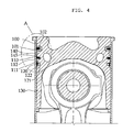
- FIG. 4 shows a cross-sectional view illustrating a piston for a diesel engine having a stable behavior of a piston ring, according to an embodiment of the present invention
- FIG. 5 shows an enlarged view of a part A in FIG. 1 .
- a piston for an engine having a stable behavior of a piston ring includes an upper body 100, a middle body 110, a lower body 120, and a connecting rod connection 130 for a connecting rod, which are integrally formed.
- a ring-shaped groove 101 is formed, and in the groove, an upper ring 102 is inserted.
- a ring-shaped groove 111 is formed, and in the groove, a middle ring 112 is inserted.
- a ring-shaped groove 121 is formed, and in the groove, an oil ring 122 is inserted.
- the upper ring 102, the middle ring 112, and the oil ring 122 are piston rings of the piston, and more rings may be inserted according to the specifications (or models) of an engine.
- a ring-shaped groove 140 having a concave-shaped deep portion is further formed where a ring is not inserted.
- a straight-line shaped (or a straight-line cross-sectional shaped) gap 145 is formed between a liner of a cylinder, and an area from the ring-shaped groove 140 formed in the middle body 110 to the oil ring 122 inserted in the lower body 120.
- the gap 145 is larger than a minute gap between the liner 150 of the cylinder, and an area from the upper ring 102 to the ring-shaped groove 140.
- the deep portion of the ring-shaped groove 140 has a concave shape, it is possible to store and flow a large amount of oil, and to store a large amount of oil by using only a minimum area between the upper ring and the middle ring. Thus, a very high controllability of a blow-by gas can be achieved.
- the ring-shaped groove 140 occupies a large area between the upper ring and the middle ring, there is a problem in that the area of a gap 145a for flow control of the blow-by gas is reduced.
- the ring-shaped groove 140 has an internal upper surface 141 which is flat or slightly slanted, and a lower surface 142 which faces the upper surface and is largely slanted downward, so that oil on the inner wall of the cylinder can be easily scraped off toward the crank case below the cylinder.
- the oil scraped off by an upper portion 143 of the ring-shaped groove 140 is flowed in the ring-shaped groove 140, and is moved toward the crank case from the inner wall of the cylinder while being on the ring-shaped groove 140.
- the gap 145 is formed, as described above.
- the blow-by gas and the oil can be flowed in, and stored or passed through the gap.
- the blow-by gas is flowed toward the crank case while passing through the middle ring 112 and the oil ring 122 via the gap 145 formed below the ring-shaped groove 140.
- the gap 145 is not formed at the upper portion 143 of the middle body 110, but formed at a lower portion 144.
- the gap 145 is divided into a straight-shaped (or straight-cross sectional) first gap 145a from the ring-shaped groove 140 to the middle ring 112, and a straight-shaped (or straight-cross sectional) second gap 145b from the middle ring 112 to the oil ring 122.
- the first gap 145a connects the ring-shaped groove 140 to the second gap 145b via the middle ring 112, thereby allowing the blow-by gas and the oil to be smoothly flowed from the ring-shaped groove 140 side to the second gap 145b side.
- the first gap 145a and the second gap 145b may be formed with a size of 0.5 to 3mm, respectively. More preferably, the first gap 145a and the second gap 145b may be optimized with a size of 0.5 to 2mm, or a size of 1 to 3mm, respectively. Herein, the first gap 145a and the second gap 145b may be differently formed from each other. When the first gap 145a and the second gap 145b are different from each other, the second gap 145b may have a size of 0.5 to 1.5mm. This stabilizes the blow-by gas, and reduces the consumption of oil.
- the first gap 145a or the second gap 145b has a size corresponding to a half of a diameter difference value obtained by subtracting the outside diameter of the piston's corresponding portion, from the inside diameter of the liner 150 of the cylinder.
- each gap (the first gap, or the second gap) is 3mm or more, the portion upwardly/downwardly supporting the middle ring 112 is reduced, thereby destabilizing behavior of the middle ring 112.
- each gap (the first gap, or the second gap) is 0.5mm or less, such a size is not enough to control and stabilize the blow-by gas. Thus, there may be no effect on the reduction of oil consumption.
- the gap 145 between the ring-shaped groove 140 and the liner 150 is fixed with a size of 7mm in the embodiment of the present invention.
- the internal upper surface 141 of the ring-shaped groove 140 may have a curved shape or a slightly inclined shape. Such a curved structure or an inclined structure of the internal upper surface 141 stabilizes the flow of the blow-by gas, and reduces the consumption of oil.
- the lower surface 142 within the ring-shaped groove 140 may be formed with a steeply downward slope while the deep portion (or a bottom surface) of the ring-shaped groove 140 may be curved. Such a structure of the ring-shaped groove may allow a large amount of oil to be stored and flowed.
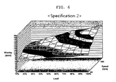
- FIG. 6 shows a graph illustrating the behavior of a blow-by gas in an 8-liter grade engine employing the piston for a diesel engine having a stable behavior of a piston ring, according to an embodiment of the present invention
- FIG. 7 shows a graph illustrating the behavior of a blow-by gas in an 11-liter grade engine employing the piston for a diesel engine having a stable behavior of a piston ring, according to an embodiment of the present invention.
- a ring-shaped groove on a middle body has a first gap 145a between its lower end and a liner, which is 0.5mm larger than another gap between its upper end and the liner.
Landscapes
- Engineering & Computer Science (AREA)
- General Engineering & Computer Science (AREA)
- Mechanical Engineering (AREA)
- Chemical & Material Sciences (AREA)
- Combustion & Propulsion (AREA)
- Pistons, Piston Rings, And Cylinders (AREA)
Abstract
Description
- The present invention relates to a piston for an engine having a stable behavior of a piston ring. More particularly the present invention relates to a piston for an engine having a stable behavior of a piston ring on which a blow-by gas passing through between a cylinder and the piston has an effect.
- As generally known in the art, a piston for an internal combustion engine performs a role of compressing air provided to a cylinder through reciprocation within the cylinder, and transferring expansion pressure caused by the air and fuel combustion, to a connecting rod.
- The piston is a component constituting a part of a combustion chamber for combustion in an engine, and includes a head part subject to high temperature and high pressure of exploded gas, a ring part, and a skirt part. The ring part has a piston ring made of special cast iron, which is put in 2 to 4 grooves dug in the circumference of the piston. The skirt part is subject to a side thrust, and has an outer diameter somewhat smaller than an inner diameter of the cylinder, against thermal expansion. The piston ring not only performs a role of maintaining the airtightness between the piston and the cylinder, but also scrapes off engine oil (or lubricant oil) on the cylinder.
- While the piston compresses air, an exhaust gas is generated by combustion through fuel injection. The exhaust gas may move into a crank case through the lateral surface of the piston. On the other hand, the engine oil within the crank case may be moved to the combustion chamber and then combusted. The exhaust gas moving from the combustion chamber into the crank case is referred to as a blow-by gas, and the consumed amount of the engine oil moved from the inside of the crank case to the combustion chamber is referred to as an oil consumption amount.
- Although the piston ring or the engine oil seals up between a cylinder wall and the piston, a gap between the cylinder wall and the piston cannot help but exist. Through such a gap, a trace amount of mixed gas is leaked into the crank case during compression stroke of the engine. The blow-by gas discharged to the crank case is transferred to a head cover.
- When the blow-by gas stays within the crank case, the pressure within a crank is increased. This increases oil leakage at respective sealing portions, and deteriorates the engine oil. For this reason, the blow-by gas passes through an oil separator. Then, the oil is collected by the oil separator, while the blow-by gas, from which the oil has been separated, is sent again to an intake manifold, and is then supplied and re-combusted, together with the intake air, in the combustion chamber, or simply discharged to the atmosphere.
- An increase in both the blow-by gas and the oil consumption has a bad effect on the performance of the engine. When the oil consumption increases, a financial burden is increased, thereby causing dissatisfaction of consumers. Also, when the blow-by gas is instable, oil consumption increases due to instable behavior of the piston ring, or the performance of a closed crankcase ventilation (CCV) system becomes low due to instability of the internal pressure of the crank case. Especially, in a case where a filter-type CCV is used, such instability has an effect on the life of a filter, which increases a financial burden of the consumers, thereby causing dissatisfaction of them.
-
FIG. 1 shows a conventional piston of a diesel engine. Referring toFIG. 1 , the conventional piston for the diesel engine includes anupper ring 102, amiddle ring 112, and anoil ring 122, provided therewithin. Between theupper ring 102 and themiddle ring 112, a ring-shaped groove 140 is formed, and there are small gaps between the upper/lower ends of the ring-shaped groove 140, and a liner.FIGs. 2 and3 show graphs illustrating pressure fluctuations of a blow-by gas in 8-liter grade and 11-liter grade diesel engines which employ the piston shown inFIG. 1 . - Referring to
FIGs. 2 and3 , although a conventional piston for a diesel engine has the ring-shaped groove 140 between theupper ring 102 and themiddle ring 112, the gaps between the upper/lower ends of the ring-shaped groove 140, and the liner are the same as each other, and relatively small. Thus, the blow-by gas coming out from the combustion chamber via theupper ring 102 stays between theupper ring 102 and themiddle ring 112, and forms a pressure, which destabilizes the behaviors of theupper ring 102 and themiddle ring 112. This destabilizes the behavior of the blow-by gas coming into the crank case via themiddle ring 112, thereby causing non-uniformity of a change in a pressure diagram of the blow-by gas, and increasing the consumption of oil. - Meanwhile, as another example of a conventional technology, Japanese Patent Publication No.
2001-214804 - As a further example of a conventional technology, Japanese Patent Publication No.
2001-214805 - Accordingly, the present invention has been made to solve the above-mentioned problems occurring in the prior art, and the present invention provides a piston for an engine having a stable behavior of a piston ring, which can stabilizes a blow-by gas passing through between the piston ring and a cylinder wall, and reduce oil consumption.
- In accordance with an aspect of the present invention, there is provided a piston for an engine having a stable behavior of a piston ring, the piston including: an upper ring, a middle ring, and an oil ring, provided in an outer circumferential portion; and a ring-shaped groove formed between the upper ring, and the middle ring, wherein the ring-shaped groove has a deep portion which has a concave shape so as to oil staying in the ring-shaped groove to be uniformly smoothly flowed, a straight-lined shaped first gap is formed between a liner of a cylinder, and an area from the ring-shaped groove to the middle ring, and the first gap is larger than a gap between the liner of the cylinder, and an area from a portion provided with the upper ring to the ring-shaped groove.
- Also, in the present invention, a straight-line shaped second gap is further formed in an area from the middle ring to the oil ring, and the second gap is larger than a gap between the liner of the cylinder, and the area from the portion provided with the upper ring to the ring-shaped groove.
- Also, the first gap and the second gap, formed between the liner of the cylinder, and the piston, have a size of 0.5 to 3mm, respectively.
- Also, the first gap and the second gap have a size of 0.5 to 2mm, respectively.
- Also, the first gap and the second gap are differently formed from each other.
- Also, when the first gap and the second gap are differently formed from each other, the second gap has a size of 0.5 to 1.5mm.
- Also, a ratio of a longest distance between the ring-shaped groove and the liner, to the first gap or the second gap, ranges from 7:1 to 7:5.
- Also, an internal upper surface of the ring-shaped groove is curved or slightly inclined.
- Also, a lower surface within the ring-shaped groove is formed with a steeply downward slope
- Also, the deep portion (or bottom surface) of the ring-shaped groove is curved.
- Also, the first gap and the second gap have a size of 1 to 3mm, respectively.
- In the present invention, it is possible to adjust the amount of a blow-by gas, which is a mixed gas flowed into a crank case from a combustion chamber by passing through a gap between the cylinder and the piston, formed below the ring-shaped groove, thereby stabilizing the behavior of the blow-by gas.
- Also, the stabilization of the behavior of the blow-by gas stabilizes the behavior of the upper ring inserted in the upper body, thereby reducing the amount of oil scraped off toward the combustion chamber by the upper ring. This can reduce oil consumption.
- Also, it is possible to stabilize the behavior of the middle ring inserted in the middle body, and to smoothly scrape off the oil on the inner wall of the cylinder toward the crank case through the space formed below the ring-shaped groove. This reduces the oil remaining on the inner wall of the cylinder, and thereby reduces the oil consumption caused by evaporation.
- Also, it is possible to stabilize the crank case's internal pressure caused by the blow-by gas, thereby improving the durability of a blow-by gas processing apparatus for processing the blow-by gas.
- Also, it is possible to prevent the oil from flowing toward the combustion chamber, to prevent the gas from leaking in the combustion chamber, and to stabilize the behavior of the piston ring.
- The above and other inventive aspects, features and embodiments of the present invention will be more apparent from the following detailed description taken in conjunction with the accompanying drawings, in which:
-
FIG. 1 shows a cross-sectional view illustrating a conventional piston of a diesel engine; -
FIG. 2 shows a graph showing press fluctuation of a blow-by gas in an 8-liter grade diesel engine employing the piston shown inFIG. 1 ; -
FIG. 3 shows a graph showing press fluctuation of a blow-by gas in an 11-liter grade diesel engine employing the piston shown inFIG. 1 ; -
FIG. 4 shows a cross-sectional view illustrating a piston for a diesel engine having a stable behavior of a piston ring, according to an embodiment of the present invention; -
FIG. 5 shows an enlarged view of a part A inFIG. 4 ; -
FIG. 6 shows a graph illustrating the behavior of a blow-by gas in an 8-liter grade engine employing a piston for a diesel engine having a stable behavior of a piston ring, according to an embodiment of the present invention; and -
FIG. 7 shows a graph illustrating the behavior of a blow-by gas in an 11-liter grade engine employing a piston for a diesel engine having a stable behavior of a piston ring, according to an embodiment of the present invention. - Hereinafter, an embodiment of a piston for an engine having a stable behavior of a piston ring, according to the present invention, will be described with reference to
FIGs 4 to 7 . - In the description, thicknesses of lines or sizes of components, shown in the drawings may be exaggerated for clarity of explanation and convenience of understanding. Also, terms that will be described below are defined in consideration of functions in the present invention, which may vary according to a user, a purpose of an operator, or usage.
-
FIG. 4 shows a cross-sectional view illustrating a piston for a diesel engine having a stable behavior of a piston ring, according to an embodiment of the present invention, andFIG. 5 shows an enlarged view of a part A inFIG. 1 . - Referring to
FIG. 4 , a piston for an engine having a stable behavior of a piston ring, according to an embodiment of the present invention, includes anupper body 100, amiddle body 110, alower body 120, and a connectingrod connection 130 for a connecting rod, which are integrally formed. - In the lower outer circumferential portion of the
upper body 100, a ring-shapedgroove 101 is formed, and in the groove, anupper ring 102 is inserted. Also, in the lower outer circumferential portion of themiddle body 110, a ring-shapedgroove 111 is formed, and in the groove, amiddle ring 112 is inserted. Also, in the lower outer circumferential portion of thelower body 120, a ring-shapedgroove 121 is formed, and in the groove, anoil ring 122 is inserted. Theupper ring 102, themiddle ring 112, and theoil ring 122 are piston rings of the piston, and more rings may be inserted according to the specifications (or models) of an engine. - Herein, in the
middle body 110, a ring-shapedgroove 140 having a concave-shaped deep portion is further formed where a ring is not inserted. A straight-line shaped (or a straight-line cross-sectional shaped)gap 145 is formed between a liner of a cylinder, and an area from the ring-shapedgroove 140 formed in themiddle body 110 to theoil ring 122 inserted in thelower body 120. Herein, thegap 145 is larger than a minute gap between theliner 150 of the cylinder, and an area from theupper ring 102 to the ring-shapedgroove 140. Since the deep portion of the ring-shapedgroove 140 has a concave shape, it is possible to store and flow a large amount of oil, and to store a large amount of oil by using only a minimum area between the upper ring and the middle ring. Thus, a very high controllability of a blow-by gas can be achieved. When the ring-shapedgroove 140 occupies a large area between the upper ring and the middle ring, there is a problem in that the area of agap 145a for flow control of the blow-by gas is reduced. - Referring to
FIGs. 4 and5 , the ring-shapedgroove 140 has an internalupper surface 141 which is flat or slightly slanted, and alower surface 142 which faces the upper surface and is largely slanted downward, so that oil on the inner wall of the cylinder can be easily scraped off toward the crank case below the cylinder. In other words, the oil scraped off by anupper portion 143 of the ring-shapedgroove 140 is flowed in the ring-shapedgroove 140, and is moved toward the crank case from the inner wall of the cylinder while being on the ring-shapedgroove 140. - Herein, between the lower portion of the ring-shaped
groove 140, and the liner, thegap 145 is formed, as described above. The blow-by gas and the oil can be flowed in, and stored or passed through the gap. The blow-by gas is flowed toward the crank case while passing through themiddle ring 112 and theoil ring 122 via thegap 145 formed below the ring-shapedgroove 140. - Herein, the
gap 145 is not formed at theupper portion 143 of themiddle body 110, but formed at alower portion 144. Thegap 145 is divided into a straight-shaped (or straight-cross sectional)first gap 145a from the ring-shapedgroove 140 to themiddle ring 112, and a straight-shaped (or straight-cross sectional)second gap 145b from themiddle ring 112 to theoil ring 122. Thefirst gap 145a connects the ring-shapedgroove 140 to thesecond gap 145b via themiddle ring 112, thereby allowing the blow-by gas and the oil to be smoothly flowed from the ring-shapedgroove 140 side to thesecond gap 145b side. - Meanwhile, the
first gap 145a and thesecond gap 145b may be formed with a size of 0.5 to 3mm, respectively. More preferably, thefirst gap 145a and thesecond gap 145b may be optimized with a size of 0.5 to 2mm, or a size of 1 to 3mm, respectively. Herein, thefirst gap 145a and thesecond gap 145b may be differently formed from each other. When thefirst gap 145a and thesecond gap 145b are different from each other, thesecond gap 145b may have a size of 0.5 to 1.5mm. This stabilizes the blow-by gas, and reduces the consumption of oil. Thefirst gap 145a or thesecond gap 145b has a size corresponding to a half of a diameter difference value obtained by subtracting the outside diameter of the piston's corresponding portion, from the inside diameter of theliner 150 of the cylinder. - When each gap (the first gap, or the second gap) is 3mm or more, the portion upwardly/downwardly supporting the
middle ring 112 is reduced, thereby destabilizing behavior of themiddle ring 112. On the other hand, when each gap (the first gap, or the second gap) is 0.5mm or less, such a size is not enough to control and stabilize the blow-by gas. Thus, there may be no effect on the reduction of oil consumption. - The ratio of the longest distance from the ring-shaped
groove 140 to theliner 150, to thegap 145, ranges from 7:1 to 7:5. Thegap 145 between the ring-shapedgroove 140 and theliner 150 is fixed with a size of 7mm in the embodiment of the present invention. The internalupper surface 141 of the ring-shapedgroove 140 may have a curved shape or a slightly inclined shape. Such a curved structure or an inclined structure of the internalupper surface 141 stabilizes the flow of the blow-by gas, and reduces the consumption of oil. Meanwhile, thelower surface 142 within the ring-shapedgroove 140 may be formed with a steeply downward slope while the deep portion (or a bottom surface) of the ring-shapedgroove 140 may be curved. Such a structure of the ring-shaped groove may allow a large amount of oil to be stored and flowed. - As described above, since there is provided the
gap 145 for allowing the blow-by gas and the oil to be flowed toward or stored in the crank case, pressure fluctuation of the blow-by gas is reduced, and behavior fluctuation of theupper ring 102 and themiddle ring 112, caused by the blow-by gas, is reduced, compared to the case where there is nogap 145 below the ring-shapedgroove 140. - Accordingly, a minute change in the shape of the
upper ring 102 according to the behavior of theupper ring 102 is reduced, and thereby it is possible for theupper ring 102 to more perfectly maintain its airtight state against the inner wall of the cylinder. Also, when the piston is placed in a compression state while moving to the upper portion of theliner 150, the amount of oil scraped off from the inner wall of the cylinder, by theupper ring 102, is reduced. - When the combustion chamber formed between the piston and the cylinder is placed from a compressed state to an explosion state, a large amount of blow-by gas can stay in the
gap 145 formed below the ring-shapedgroove 140. Thus, pressure fluctuation is reduced, and the blow-by gas can be stably and smoothly moved downward, which stabilizes the behavior of themiddle ring 112 inserted in themiddle body 110. - Since the behavior of the
middle ring 112 is stabilized, and thegap 145 is provided below the ring-shapedgroove 140, it is possible to smoothly scrape off the oil on the inner wall of the cylinder, toward the crank case side. Furthermore, it is possible to reduce the consumption of oil, caused by evaporation, because the amount of the oil remaining on the inner wall of the cylinder is reduced. Herein, since the internal pressure of the crank case, caused by the blow-by gas, is stabilized, it is possible to improve the durability in a blow-by gas processing apparatus for processing the blow-by gas. -
FIG. 6 shows a graph illustrating the behavior of a blow-by gas in an 8-liter grade engine employing the piston for a diesel engine having a stable behavior of a piston ring, according to an embodiment of the present invention, andFIG. 7 shows a graph illustrating the behavior of a blow-by gas in an 11-liter grade engine employing the piston for a diesel engine having a stable behavior of a piston ring, according to an embodiment of the present invention. - Referring to
FIGs. 2 and3 , as a result of the test on the 8-liter grade engine and the 11-liter grade engine, a difference of the amounts of the blow-by gas according to a load was non-uniform in specification (or model) 1. On the other hand, referring toFIGs. 5 and6 , in the case ofspecification 2, a change in the blow-by gas according to a load was uniform. Also, as noted in Table 1, it was determined that oil consumption was reduced by 81% and 34%, respectively.Table 1 Specification 1Specification 2Change in oil consumption 8-liter grade engine 8.58 ℓ/100h 1.60 ℓ/100hr Reduction of 81% 11-liter grade engine 3.57 ℓ/100hr 2.36 ℓ/100hr Reduction of 34 % - Herein, in the case of
specification 1, only a ring-shaped groove exists on a generally used piston body, which has a uniform gap between its upper/lower ends and a liner. Meanwhile, in the case ofspecification 2, a ring-shaped groove on a middle body has afirst gap 145a between its lower end and a liner, which is 0.5mm larger than another gap between its upper end and the liner.
Claims (11)
- A piston for an engine having a stable behavior of a piston ring, the piston comprising:an upper ring(102), a middle ring(112), and an oil ring(122), which are provided at an outer circumferential portion; anda ring-shaped groove(140) formed between the upper ring(102) and the middle ring(112),wherein the ring-shaped groove(140) has a deep portion which has a concave shape so as to oil staying in the ring-shaped groove(140) to be uniformly smoothly flowed, a first gap(145a) having a shape of a straight line is formed between a liner(150) of a cylinder and an area from the ring-shaped groove(140) to the middle ring(112), and the first gap(145a) is larger than a gap between the liner(150) of the cylinder and an area from a portion provided with the upper ring (102) to the ring-shaped groove (140).
- The piston for the engine having the stable behavior of the piston ring as claimed in claim 1, wherein a second gap(145b) having a shape of a straight line is further formed from the middle ring(112) to the oil ring(122), and the second gap(145b) is larger than the gap between the liner(150) of the cylinder and the area from the portion provided with the upper ring(102) to the ring-shaped groove (140).
- The piston for the engine having the stable behavior of the piston ring as claimed in claim 1, wherein the first gap(145a) and the second gap(145b) formed between the liner(150) of the cylinder and the piston have a size of 0.5 to 3mm, respectively.
- The piston for the engine having the stable behavior of the piston ring as claimed in claim 3, wherein the first gap(145a) and the second gap(145b) have a size of 0.5 to 2mm, respectively.
- The piston for the engine having the stable behavior of the piston ring as claimed in claim 2, wherein the first gap(145a) and the second gap(145b) are differently formed from each other.
- The piston for the engine having the stable behavior of the piston ring as claimed in claim 1, wherein when the first gap(145a) and the second gap(145b) are differently formed from each other, the second gap(145b) has a size of 0.5 to 1.5mm.
- The piston for the engine having the stable behavior of the piston ring as claimed in claim 1 or 2, wherein a ratio of a longest distance between the ring-shaped groove(140) and the liner(150) with respect to the first gap(145a) or the second gap(145b) ranges from 7:1 to 7:5.
- The piston for the engine having the stable behavior of the piston ring as claimed in claim 1 or 2, wherein an internal upper surface(141) of the ring-shaped groove(140) is curved or slightly inclined.
- The piston for the engine having the stable behavior of the piston ring as claimed in claim 1, wherein a lower surface(142) within the ring-shaped groove(140) is formed with a steeply downward slope
- The piston for the engine having the stable behavior of the piston ring as claimed in claim 1, wherein the deep portion of the ring-shaped groove(140) is curved.
- The piston for the engine having the stable behavior of the piston ring as claimed in claim 3, wherein the first gap(145a) and the second gap(145b) have a size of 1 to 3mm, respectively.
Applications Claiming Priority (2)
| Application Number | Priority Date | Filing Date | Title |
|---|---|---|---|
| KR20090074081 | 2009-08-12 | ||
| KR1020100053844A KR102026480B1 (en) | 2009-08-12 | 2010-06-08 | Piston for engine having stabled behavior of piston ring |
Publications (2)
| Publication Number | Publication Date |
|---|---|
| EP2284422A1 true EP2284422A1 (en) | 2011-02-16 |
| EP2284422B1 EP2284422B1 (en) | 2012-11-07 |
Family
ID=43066823
Family Applications (1)
| Application Number | Title | Priority Date | Filing Date |
|---|---|---|---|
| EP10008169A Active EP2284422B1 (en) | 2009-08-12 | 2010-08-05 | Piston for engine having stable behavior of piston ring |
Country Status (2)
| Country | Link |
|---|---|
| US (1) | US8353267B2 (en) |
| EP (1) | EP2284422B1 (en) |
Cited By (1)
| Publication number | Priority date | Publication date | Assignee | Title |
|---|---|---|---|---|
| CN108431467A (en) * | 2016-03-16 | 2018-08-21 | 联邦摩高布尔沙伊德公司 | Multi-piece oil control piston rings with reduced friction |
Families Citing this family (3)
| Publication number | Priority date | Publication date | Assignee | Title |
|---|---|---|---|---|
| US10113643B2 (en) * | 2014-03-18 | 2018-10-30 | Ford Global Technologies, Llc | Compression piston ring for an internal combustion engine |
| US20170284544A1 (en) | 2016-03-30 | 2017-10-05 | Electro-Motive Diesel, Inc. | Piston with variable depth groove root |
| DE102020122862A1 (en) * | 2020-09-01 | 2022-03-03 | Federal-Mogul Burscheid Gmbh | PISTON RING SYSTEM FOR AN INTERNAL COMBUSTION ENGINE WITH DIRECT WATER INJECTION |
Citations (5)
| Publication number | Priority date | Publication date | Assignee | Title |
|---|---|---|---|---|
| SU723200A1 (en) * | 1978-04-14 | 1980-03-25 | Брянский Институт Транспортного Машиностроения | Piston |
| GB1584087A (en) * | 1976-10-18 | 1981-02-04 | Schmidt Gmbh Karl | Piston |
| GB2268244A (en) * | 1992-06-22 | 1994-01-05 | Riken Kk | Pisto for internal combustion engines |
| JP2001214804A (en) | 2000-01-28 | 2001-08-10 | Suzuki Motor Corp | Piston |
| JP2001214805A (en) | 2000-01-28 | 2001-08-10 | Nippon Piston Ring Co Ltd | Piston |
Family Cites Families (3)
| Publication number | Priority date | Publication date | Assignee | Title |
|---|---|---|---|---|
| DE2507899C3 (en) * | 1975-02-24 | 1980-06-04 | Karl Schmidt Gmbh, 7107 Neckarsulm | Light alloy pistons for diesel internal combustion engines |
| DE2828749C2 (en) * | 1978-06-30 | 1983-10-20 | M.A.N. Maschinenfabrik Augsburg-Nürnberg AG, 8500 Nürnberg | Pistons for internal combustion engines |
| US6557514B1 (en) * | 2001-10-23 | 2003-05-06 | Federal-Mogul World Wide, Inc. | Closed gallery monobloc piston having oil drainage groove |
-
2010
- 2010-08-05 EP EP10008169A patent/EP2284422B1/en active Active
- 2010-08-12 US US12/855,041 patent/US8353267B2/en active Active
Patent Citations (5)
| Publication number | Priority date | Publication date | Assignee | Title |
|---|---|---|---|---|
| GB1584087A (en) * | 1976-10-18 | 1981-02-04 | Schmidt Gmbh Karl | Piston |
| SU723200A1 (en) * | 1978-04-14 | 1980-03-25 | Брянский Институт Транспортного Машиностроения | Piston |
| GB2268244A (en) * | 1992-06-22 | 1994-01-05 | Riken Kk | Pisto for internal combustion engines |
| JP2001214804A (en) | 2000-01-28 | 2001-08-10 | Suzuki Motor Corp | Piston |
| JP2001214805A (en) | 2000-01-28 | 2001-08-10 | Nippon Piston Ring Co Ltd | Piston |
Non-Patent Citations (1)
| Title |
|---|
| DATABASE WPI Week 198045, Derwent World Patents Index; AN 1980-K8125C * |
Cited By (2)
| Publication number | Priority date | Publication date | Assignee | Title |
|---|---|---|---|---|
| CN108431467A (en) * | 2016-03-16 | 2018-08-21 | 联邦摩高布尔沙伊德公司 | Multi-piece oil control piston rings with reduced friction |
| CN108431467B (en) * | 2016-03-16 | 2021-04-20 | 联邦摩高布尔沙伊德公司 | Multi-piece oil controlled piston rings with reduced friction |
Also Published As
| Publication number | Publication date |
|---|---|
| US8353267B2 (en) | 2013-01-15 |
| EP2284422B1 (en) | 2012-11-07 |
| US20110036322A1 (en) | 2011-02-17 |
Similar Documents
| Publication | Publication Date | Title |
|---|---|---|
| US8365696B2 (en) | Piston device for internal combustion engines | |
| EP2284422B1 (en) | Piston for engine having stable behavior of piston ring | |
| US9027933B2 (en) | Engine | |
| US20130068188A1 (en) | Arrangement in a combustion engine | |
| JPS6140448A (en) | Special form piston with piston ring | |
| WO2019203358A1 (en) | Piston ring | |
| US7004140B2 (en) | Piston structure of engine | |
| JP6389865B2 (en) | Piston for internal combustion engine | |
| US20130287325A1 (en) | Bearing Arrangement For A Crankshaft Of An Internal Combustion Engine | |
| KR20130083608A (en) | Exhaust valve and valve seat for supercharged gas engine | |
| KR102026480B1 (en) | Piston for engine having stabled behavior of piston ring | |
| US7429048B1 (en) | Piston ring with projection | |
| JP2013238117A (en) | Internal combustion engine | |
| CN118728587A (en) | Internal combustion engine and cylinder block | |
| JPS63131839A (en) | Piston for internal combustion engine | |
| JPH11351402A (en) | Valve stem seal | |
| EP4575275A1 (en) | Piston ring with trapezoidal openning | |
| KR102429575B1 (en) | Piston | |
| JP2590145B2 (en) | Piston for internal combustion engine | |
| CN118049324A (en) | Internal combustion engine | |
| JPS6126565Y2 (en) | ||
| JP2001214805A (en) | Piston | |
| JPS647215B2 (en) | ||
| EP4735749A1 (en) | A piston for a reciprocating internal combustion piston engine, a reciprocating internal combustion engine and use of such piston | |
| EP1707786A1 (en) | Two-cycle internal combustion engine |
Legal Events
| Date | Code | Title | Description |
|---|---|---|---|
| PUAI | Public reference made under article 153(3) epc to a published international application that has entered the european phase |
Free format text: ORIGINAL CODE: 0009012 |
|
| AK | Designated contracting states |
Kind code of ref document: A1 Designated state(s): AL AT BE BG CH CY CZ DE DK EE ES FI FR GB GR HR HU IE IS IT LI LT LU LV MC MK MT NL NO PL PT RO SE SI SK SM TR |
|
| AX | Request for extension of the european patent |
Extension state: BA ME RS |
|
| 17P | Request for examination filed |
Effective date: 20110816 |
|
| RIC1 | Information provided on ipc code assigned before grant |
Ipc: F02F 3/00 20060101ALI20120405BHEP Ipc: F16J 9/00 20060101ALI20120405BHEP Ipc: F16J 1/09 20060101AFI20120405BHEP |
|
| GRAP | Despatch of communication of intention to grant a patent |
Free format text: ORIGINAL CODE: EPIDOSNIGR1 |
|
| GRAS | Grant fee paid |
Free format text: ORIGINAL CODE: EPIDOSNIGR3 |
|
| GRAA | (expected) grant |
Free format text: ORIGINAL CODE: 0009210 |
|
| AK | Designated contracting states |
Kind code of ref document: B1 Designated state(s): AL AT BE BG CH CY CZ DE DK EE ES FI FR GB GR HR HU IE IS IT LI LT LU LV MC MK MT NL NO PL PT RO SE SI SK SM TR |
|
| REG | Reference to a national code |
Ref country code: GB Ref legal event code: FG4D |
|
| REG | Reference to a national code |
Ref country code: CH Ref legal event code: EP Ref country code: AT Ref legal event code: REF Ref document number: 583146 Country of ref document: AT Kind code of ref document: T Effective date: 20121115 |
|
| REG | Reference to a national code |
Ref country code: IE Ref legal event code: FG4D |
|
| REG | Reference to a national code |
Ref country code: DE Ref legal event code: R096 Ref document number: 602010003474 Country of ref document: DE Effective date: 20130103 |
|
| REG | Reference to a national code |
Ref country code: AT Ref legal event code: MK05 Ref document number: 583146 Country of ref document: AT Kind code of ref document: T Effective date: 20121107 |
|
| REG | Reference to a national code |
Ref country code: NL Ref legal event code: VDEP Effective date: 20121107 |
|
| REG | Reference to a national code |
Ref country code: LT Ref legal event code: MG4D |
|
| PG25 | Lapsed in a contracting state [announced via postgrant information from national office to epo] |
Ref country code: LT Free format text: LAPSE BECAUSE OF FAILURE TO SUBMIT A TRANSLATION OF THE DESCRIPTION OR TO PAY THE FEE WITHIN THE PRESCRIBED TIME-LIMIT Effective date: 20121107 Ref country code: HR Free format text: LAPSE BECAUSE OF FAILURE TO SUBMIT A TRANSLATION OF THE DESCRIPTION OR TO PAY THE FEE WITHIN THE PRESCRIBED TIME-LIMIT Effective date: 20121107 Ref country code: SE Free format text: LAPSE BECAUSE OF FAILURE TO SUBMIT A TRANSLATION OF THE DESCRIPTION OR TO PAY THE FEE WITHIN THE PRESCRIBED TIME-LIMIT Effective date: 20121107 Ref country code: NO Free format text: LAPSE BECAUSE OF FAILURE TO SUBMIT A TRANSLATION OF THE DESCRIPTION OR TO PAY THE FEE WITHIN THE PRESCRIBED TIME-LIMIT Effective date: 20130207 Ref country code: IS Free format text: LAPSE BECAUSE OF FAILURE TO SUBMIT A TRANSLATION OF THE DESCRIPTION OR TO PAY THE FEE WITHIN THE PRESCRIBED TIME-LIMIT Effective date: 20130307 Ref country code: FI Free format text: LAPSE BECAUSE OF FAILURE TO SUBMIT A TRANSLATION OF THE DESCRIPTION OR TO PAY THE FEE WITHIN THE PRESCRIBED TIME-LIMIT Effective date: 20121107 Ref country code: NL Free format text: LAPSE BECAUSE OF FAILURE TO SUBMIT A TRANSLATION OF THE DESCRIPTION OR TO PAY THE FEE WITHIN THE PRESCRIBED TIME-LIMIT Effective date: 20121107 |
|
| PG25 | Lapsed in a contracting state [announced via postgrant information from national office to epo] |
Ref country code: PT Free format text: LAPSE BECAUSE OF FAILURE TO SUBMIT A TRANSLATION OF THE DESCRIPTION OR TO PAY THE FEE WITHIN THE PRESCRIBED TIME-LIMIT Effective date: 20130307 Ref country code: LV Free format text: LAPSE BECAUSE OF FAILURE TO SUBMIT A TRANSLATION OF THE DESCRIPTION OR TO PAY THE FEE WITHIN THE PRESCRIBED TIME-LIMIT Effective date: 20121107 Ref country code: PL Free format text: LAPSE BECAUSE OF FAILURE TO SUBMIT A TRANSLATION OF THE DESCRIPTION OR TO PAY THE FEE WITHIN THE PRESCRIBED TIME-LIMIT Effective date: 20121107 Ref country code: BE Free format text: LAPSE BECAUSE OF FAILURE TO SUBMIT A TRANSLATION OF THE DESCRIPTION OR TO PAY THE FEE WITHIN THE PRESCRIBED TIME-LIMIT Effective date: 20121107 Ref country code: GR Free format text: LAPSE BECAUSE OF FAILURE TO SUBMIT A TRANSLATION OF THE DESCRIPTION OR TO PAY THE FEE WITHIN THE PRESCRIBED TIME-LIMIT Effective date: 20130208 Ref country code: SI Free format text: LAPSE BECAUSE OF FAILURE TO SUBMIT A TRANSLATION OF THE DESCRIPTION OR TO PAY THE FEE WITHIN THE PRESCRIBED TIME-LIMIT Effective date: 20121107 |
|
| PG25 | Lapsed in a contracting state [announced via postgrant information from national office to epo] |
Ref country code: AT Free format text: LAPSE BECAUSE OF FAILURE TO SUBMIT A TRANSLATION OF THE DESCRIPTION OR TO PAY THE FEE WITHIN THE PRESCRIBED TIME-LIMIT Effective date: 20121107 |
|
| PG25 | Lapsed in a contracting state [announced via postgrant information from national office to epo] |
Ref country code: SK Free format text: LAPSE BECAUSE OF FAILURE TO SUBMIT A TRANSLATION OF THE DESCRIPTION OR TO PAY THE FEE WITHIN THE PRESCRIBED TIME-LIMIT Effective date: 20121107 Ref country code: EE Free format text: LAPSE BECAUSE OF FAILURE TO SUBMIT A TRANSLATION OF THE DESCRIPTION OR TO PAY THE FEE WITHIN THE PRESCRIBED TIME-LIMIT Effective date: 20121107 Ref country code: BG Free format text: LAPSE BECAUSE OF FAILURE TO SUBMIT A TRANSLATION OF THE DESCRIPTION OR TO PAY THE FEE WITHIN THE PRESCRIBED TIME-LIMIT Effective date: 20130207 Ref country code: CZ Free format text: LAPSE BECAUSE OF FAILURE TO SUBMIT A TRANSLATION OF THE DESCRIPTION OR TO PAY THE FEE WITHIN THE PRESCRIBED TIME-LIMIT Effective date: 20121107 Ref country code: DK Free format text: LAPSE BECAUSE OF FAILURE TO SUBMIT A TRANSLATION OF THE DESCRIPTION OR TO PAY THE FEE WITHIN THE PRESCRIBED TIME-LIMIT Effective date: 20121107 |
|
| PLBI | Opposition filed |
Free format text: ORIGINAL CODE: 0009260 |
|
| PG25 | Lapsed in a contracting state [announced via postgrant information from national office to epo] |
Ref country code: RO Free format text: LAPSE BECAUSE OF FAILURE TO SUBMIT A TRANSLATION OF THE DESCRIPTION OR TO PAY THE FEE WITHIN THE PRESCRIBED TIME-LIMIT Effective date: 20121107 |
|
| 26 | Opposition filed |
Opponent name: MAHLE INTERNATIONAL GMBH Effective date: 20130806 |
|
| PLAX | Notice of opposition and request to file observation + time limit sent |
Free format text: ORIGINAL CODE: EPIDOSNOBS2 |
|
| PG25 | Lapsed in a contracting state [announced via postgrant information from national office to epo] |
Ref country code: ES Free format text: LAPSE BECAUSE OF FAILURE TO SUBMIT A TRANSLATION OF THE DESCRIPTION OR TO PAY THE FEE WITHIN THE PRESCRIBED TIME-LIMIT Effective date: 20130218 |
|
| REG | Reference to a national code |
Ref country code: DE Ref legal event code: R026 Ref document number: 602010003474 Country of ref document: DE Effective date: 20130806 |
|
| PG25 | Lapsed in a contracting state [announced via postgrant information from national office to epo] |
Ref country code: CY Free format text: LAPSE BECAUSE OF FAILURE TO SUBMIT A TRANSLATION OF THE DESCRIPTION OR TO PAY THE FEE WITHIN THE PRESCRIBED TIME-LIMIT Effective date: 20121107 |
|
| PLAF | Information modified related to communication of a notice of opposition and request to file observations + time limit |
Free format text: ORIGINAL CODE: EPIDOSCOBS2 |
|
| PG25 | Lapsed in a contracting state [announced via postgrant information from national office to epo] |
Ref country code: MC Free format text: LAPSE BECAUSE OF FAILURE TO SUBMIT A TRANSLATION OF THE DESCRIPTION OR TO PAY THE FEE WITHIN THE PRESCRIBED TIME-LIMIT Effective date: 20121107 |
|
| REG | Reference to a national code |
Ref country code: IE Ref legal event code: MM4A |
|
| PLBB | Reply of patent proprietor to notice(s) of opposition received |
Free format text: ORIGINAL CODE: EPIDOSNOBS3 |
|
| PG25 | Lapsed in a contracting state [announced via postgrant information from national office to epo] |
Ref country code: IE Free format text: LAPSE BECAUSE OF NON-PAYMENT OF DUE FEES Effective date: 20130805 |
|
| REG | Reference to a national code |
Ref country code: CH Ref legal event code: PL |
|
| PG25 | Lapsed in a contracting state [announced via postgrant information from national office to epo] |
Ref country code: CH Free format text: LAPSE BECAUSE OF NON-PAYMENT OF DUE FEES Effective date: 20140831 Ref country code: LI Free format text: LAPSE BECAUSE OF NON-PAYMENT OF DUE FEES Effective date: 20140831 |
|
| PG25 | Lapsed in a contracting state [announced via postgrant information from national office to epo] |
Ref country code: SM Free format text: LAPSE BECAUSE OF FAILURE TO SUBMIT A TRANSLATION OF THE DESCRIPTION OR TO PAY THE FEE WITHIN THE PRESCRIBED TIME-LIMIT Effective date: 20121107 |
|
| REG | Reference to a national code |
Ref country code: FR Ref legal event code: PLFP Year of fee payment: 6 |
|
| PG25 | Lapsed in a contracting state [announced via postgrant information from national office to epo] |
Ref country code: TR Free format text: LAPSE BECAUSE OF FAILURE TO SUBMIT A TRANSLATION OF THE DESCRIPTION OR TO PAY THE FEE WITHIN THE PRESCRIBED TIME-LIMIT Effective date: 20121107 Ref country code: MT Free format text: LAPSE BECAUSE OF FAILURE TO SUBMIT A TRANSLATION OF THE DESCRIPTION OR TO PAY THE FEE WITHIN THE PRESCRIBED TIME-LIMIT Effective date: 20121107 |
|
| PG25 | Lapsed in a contracting state [announced via postgrant information from national office to epo] |
Ref country code: MK Free format text: LAPSE BECAUSE OF FAILURE TO SUBMIT A TRANSLATION OF THE DESCRIPTION OR TO PAY THE FEE WITHIN THE PRESCRIBED TIME-LIMIT Effective date: 20121107 Ref country code: LU Free format text: LAPSE BECAUSE OF NON-PAYMENT OF DUE FEES Effective date: 20130805 Ref country code: HU Free format text: LAPSE BECAUSE OF FAILURE TO SUBMIT A TRANSLATION OF THE DESCRIPTION OR TO PAY THE FEE WITHIN THE PRESCRIBED TIME-LIMIT; INVALID AB INITIO Effective date: 20100805 |
|
| PLCK | Communication despatched that opposition was rejected |
Free format text: ORIGINAL CODE: EPIDOSNREJ1 |
|
| APBM | Appeal reference recorded |
Free format text: ORIGINAL CODE: EPIDOSNREFNO |
|
| APBP | Date of receipt of notice of appeal recorded |
Free format text: ORIGINAL CODE: EPIDOSNNOA2O |
|
| APAH | Appeal reference modified |
Free format text: ORIGINAL CODE: EPIDOSCREFNO |
|
| APBQ | Date of receipt of statement of grounds of appeal recorded |
Free format text: ORIGINAL CODE: EPIDOSNNOA3O |
|
| REG | Reference to a national code |
Ref country code: FR Ref legal event code: PLFP Year of fee payment: 7 |
|
| PLAB | Opposition data, opponent's data or that of the opponent's representative modified |
Free format text: ORIGINAL CODE: 0009299OPPO |
|
| R26 | Opposition filed (corrected) |
Opponent name: MAHLE INTERNATIONAL GMBH Effective date: 20130806 |
|
| REG | Reference to a national code |
Ref country code: FR Ref legal event code: PLFP Year of fee payment: 8 |
|
| REG | Reference to a national code |
Ref country code: DE Ref legal event code: R100 Ref document number: 602010003474 Country of ref document: DE |
|
| APBU | Appeal procedure closed |
Free format text: ORIGINAL CODE: EPIDOSNNOA9O |
|
| REG | Reference to a national code |
Ref country code: FR Ref legal event code: PLFP Year of fee payment: 9 |
|
| PLBN | Opposition rejected |
Free format text: ORIGINAL CODE: 0009273 |
|
| STAA | Information on the status of an ep patent application or granted ep patent |
Free format text: STATUS: OPPOSITION REJECTED |
|
| 27O | Opposition rejected |
Effective date: 20180611 |
|
| PG25 | Lapsed in a contracting state [announced via postgrant information from national office to epo] |
Ref country code: AL Free format text: LAPSE BECAUSE OF FAILURE TO SUBMIT A TRANSLATION OF THE DESCRIPTION OR TO PAY THE FEE WITHIN THE PRESCRIBED TIME-LIMIT Effective date: 20121107 |
|
| REG | Reference to a national code |
Ref country code: DE Ref legal event code: R081 Ref document number: 602010003474 Country of ref document: DE Owner name: HD HYUNDAI INFRACORE CO., LTD., KR Free format text: FORMER OWNER: DOOSAN INFRACORE CO., LTD., INCHEON, KR |
|
| PGFP | Annual fee paid to national office [announced via postgrant information from national office to epo] |
Ref country code: GB Payment date: 20250612 Year of fee payment: 16 |
|
| PGFP | Annual fee paid to national office [announced via postgrant information from national office to epo] |
Ref country code: FR Payment date: 20250610 Year of fee payment: 16 |
|
| PGFP | Annual fee paid to national office [announced via postgrant information from national office to epo] |
Ref country code: DE Payment date: 20250611 Year of fee payment: 16 |
|
| PGFP | Annual fee paid to national office [announced via postgrant information from national office to epo] |
Ref country code: IT Payment date: 20250722 Year of fee payment: 16 |