EP2284323A1 - Swing drive controller and construction machine including the same - Google Patents
Swing drive controller and construction machine including the same Download PDFInfo
- Publication number
- EP2284323A1 EP2284323A1 EP08776907A EP08776907A EP2284323A1 EP 2284323 A1 EP2284323 A1 EP 2284323A1 EP 08776907 A EP08776907 A EP 08776907A EP 08776907 A EP08776907 A EP 08776907A EP 2284323 A1 EP2284323 A1 EP 2284323A1
- Authority
- EP
- European Patent Office
- Prior art keywords
- turning
- electric motor
- rotation
- speed
- rotation speed
- Prior art date
- Legal status (The legal status is an assumption and is not a legal conclusion. Google has not performed a legal analysis and makes no representation as to the accuracy of the status listed.)
- Granted
Links
Images







Classifications
-
- B—PERFORMING OPERATIONS; TRANSPORTING
- B60—VEHICLES IN GENERAL
- B60W—CONJOINT CONTROL OF VEHICLE SUB-UNITS OF DIFFERENT TYPE OR DIFFERENT FUNCTION; CONTROL SYSTEMS SPECIALLY ADAPTED FOR HYBRID VEHICLES; ROAD VEHICLE DRIVE CONTROL SYSTEMS FOR PURPOSES NOT RELATED TO THE CONTROL OF A PARTICULAR SUB-UNIT
- B60W20/00—Control systems specially adapted for hybrid vehicles
- B60W20/10—Controlling the power contribution of each of the prime movers to meet required power demand
- B60W20/13—Controlling the power contribution of each of the prime movers to meet required power demand in order to stay within battery power input or output limits; in order to prevent overcharging or battery depletion
-
- B—PERFORMING OPERATIONS; TRANSPORTING
- B60—VEHICLES IN GENERAL
- B60K—ARRANGEMENT OR MOUNTING OF PROPULSION UNITS OR OF TRANSMISSIONS IN VEHICLES; ARRANGEMENT OR MOUNTING OF PLURAL DIVERSE PRIME-MOVERS IN VEHICLES; AUXILIARY DRIVES FOR VEHICLES; INSTRUMENTATION OR DASHBOARDS FOR VEHICLES; ARRANGEMENTS IN CONNECTION WITH COOLING, AIR INTAKE, GAS EXHAUST OR FUEL SUPPLY OF PROPULSION UNITS IN VEHICLES
- B60K6/00—Arrangement or mounting of plural diverse prime-movers for mutual or common propulsion, e.g. hybrid propulsion systems comprising electric motors and internal combustion engines
- B60K6/20—Arrangement or mounting of plural diverse prime-movers for mutual or common propulsion, e.g. hybrid propulsion systems comprising electric motors and internal combustion engines the prime-movers consisting of electric motors and internal combustion engines, e.g. HEVs
- B60K6/42—Arrangement or mounting of plural diverse prime-movers for mutual or common propulsion, e.g. hybrid propulsion systems comprising electric motors and internal combustion engines the prime-movers consisting of electric motors and internal combustion engines, e.g. HEVs characterised by the architecture of the hybrid electric vehicle
- B60K6/48—Parallel type
-
- B—PERFORMING OPERATIONS; TRANSPORTING
- B60—VEHICLES IN GENERAL
- B60K—ARRANGEMENT OR MOUNTING OF PROPULSION UNITS OR OF TRANSMISSIONS IN VEHICLES; ARRANGEMENT OR MOUNTING OF PLURAL DIVERSE PRIME-MOVERS IN VEHICLES; AUXILIARY DRIVES FOR VEHICLES; INSTRUMENTATION OR DASHBOARDS FOR VEHICLES; ARRANGEMENTS IN CONNECTION WITH COOLING, AIR INTAKE, GAS EXHAUST OR FUEL SUPPLY OF PROPULSION UNITS IN VEHICLES
- B60K25/00—Auxiliary drives
- B60K25/04—Auxiliary drives from static or dynamic pressure or vacuum, developed by the engine
-
- B—PERFORMING OPERATIONS; TRANSPORTING
- B60—VEHICLES IN GENERAL
- B60L—PROPULSION OF ELECTRICALLY-PROPELLED VEHICLES; SUPPLYING ELECTRIC POWER FOR AUXILIARY EQUIPMENT OF ELECTRICALLY-PROPELLED VEHICLES; ELECTRODYNAMIC BRAKE SYSTEMS FOR VEHICLES IN GENERAL; MAGNETIC SUSPENSION OR LEVITATION FOR VEHICLES; MONITORING OPERATING VARIABLES OF ELECTRICALLY-PROPELLED VEHICLES; ELECTRIC SAFETY DEVICES FOR ELECTRICALLY-PROPELLED VEHICLES
- B60L1/00—Supplying electric power to auxiliary equipment of vehicles
- B60L1/003—Supplying electric power to auxiliary equipment of vehicles to auxiliary motors, e.g. for pumps, compressors
-
- B—PERFORMING OPERATIONS; TRANSPORTING
- B60—VEHICLES IN GENERAL
- B60L—PROPULSION OF ELECTRICALLY-PROPELLED VEHICLES; SUPPLYING ELECTRIC POWER FOR AUXILIARY EQUIPMENT OF ELECTRICALLY-PROPELLED VEHICLES; ELECTRODYNAMIC BRAKE SYSTEMS FOR VEHICLES IN GENERAL; MAGNETIC SUSPENSION OR LEVITATION FOR VEHICLES; MONITORING OPERATING VARIABLES OF ELECTRICALLY-PROPELLED VEHICLES; ELECTRIC SAFETY DEVICES FOR ELECTRICALLY-PROPELLED VEHICLES
- B60L1/00—Supplying electric power to auxiliary equipment of vehicles
- B60L1/20—Energy regeneration from auxiliary equipment
-
- B—PERFORMING OPERATIONS; TRANSPORTING
- B60—VEHICLES IN GENERAL
- B60W—CONJOINT CONTROL OF VEHICLE SUB-UNITS OF DIFFERENT TYPE OR DIFFERENT FUNCTION; CONTROL SYSTEMS SPECIALLY ADAPTED FOR HYBRID VEHICLES; ROAD VEHICLE DRIVE CONTROL SYSTEMS FOR PURPOSES NOT RELATED TO THE CONTROL OF A PARTICULAR SUB-UNIT
- B60W10/00—Conjoint control of vehicle sub-units of different type or different function
- B60W10/04—Conjoint control of vehicle sub-units of different type or different function including control of propulsion units
- B60W10/08—Conjoint control of vehicle sub-units of different type or different function including control of propulsion units including control of electric propulsion units, e.g. motors or generators
-
- E—FIXED CONSTRUCTIONS
- E02—HYDRAULIC ENGINEERING; FOUNDATIONS; SOIL SHIFTING
- E02F—DREDGING; SOIL-SHIFTING
- E02F9/00—Component parts of dredgers or soil-shifting machines, not restricted to one of the kinds covered by groups E02F3/00 - E02F7/00
- E02F9/08—Superstructures; Supports for superstructures
- E02F9/10—Supports for movable superstructures mounted on travelling or walking gears or on other superstructures
- E02F9/12—Slewing or traversing gears
- E02F9/121—Turntables, i.e. structure rotatable about 360°
- E02F9/128—Braking systems
-
- E—FIXED CONSTRUCTIONS
- E02—HYDRAULIC ENGINEERING; FOUNDATIONS; SOIL SHIFTING
- E02F—DREDGING; SOIL-SHIFTING
- E02F9/00—Component parts of dredgers or soil-shifting machines, not restricted to one of the kinds covered by groups E02F3/00 - E02F7/00
- E02F9/20—Drives; Control devices
- E02F9/2058—Electric or electro-mechanical or mechanical control devices of vehicle sub-units
- E02F9/2062—Control of propulsion units
- E02F9/2075—Control of propulsion units of the hybrid type
-
- E—FIXED CONSTRUCTIONS
- E02—HYDRAULIC ENGINEERING; FOUNDATIONS; SOIL SHIFTING
- E02F—DREDGING; SOIL-SHIFTING
- E02F9/00—Component parts of dredgers or soil-shifting machines, not restricted to one of the kinds covered by groups E02F3/00 - E02F7/00
- E02F9/20—Drives; Control devices
- E02F9/22—Hydraulic or pneumatic drives
- E02F9/2246—Control of prime movers, e.g. depending on the hydraulic load of work tools
-
- B—PERFORMING OPERATIONS; TRANSPORTING
- B60—VEHICLES IN GENERAL
- B60K—ARRANGEMENT OR MOUNTING OF PROPULSION UNITS OR OF TRANSMISSIONS IN VEHICLES; ARRANGEMENT OR MOUNTING OF PLURAL DIVERSE PRIME-MOVERS IN VEHICLES; AUXILIARY DRIVES FOR VEHICLES; INSTRUMENTATION OR DASHBOARDS FOR VEHICLES; ARRANGEMENTS IN CONNECTION WITH COOLING, AIR INTAKE, GAS EXHAUST OR FUEL SUPPLY OF PROPULSION UNITS IN VEHICLES
- B60K1/00—Arrangement or mounting of electrical propulsion units
- B60K1/02—Arrangement or mounting of electrical propulsion units comprising more than one electric motor
-
- B—PERFORMING OPERATIONS; TRANSPORTING
- B60—VEHICLES IN GENERAL
- B60K—ARRANGEMENT OR MOUNTING OF PROPULSION UNITS OR OF TRANSMISSIONS IN VEHICLES; ARRANGEMENT OR MOUNTING OF PLURAL DIVERSE PRIME-MOVERS IN VEHICLES; AUXILIARY DRIVES FOR VEHICLES; INSTRUMENTATION OR DASHBOARDS FOR VEHICLES; ARRANGEMENTS IN CONNECTION WITH COOLING, AIR INTAKE, GAS EXHAUST OR FUEL SUPPLY OF PROPULSION UNITS IN VEHICLES
- B60K17/00—Arrangement or mounting of transmissions in vehicles
- B60K17/04—Arrangement or mounting of transmissions in vehicles characterised by arrangement, location or kind of gearing
- B60K17/10—Arrangement or mounting of transmissions in vehicles characterised by arrangement, location or kind of gearing of fluid gearing
-
- B—PERFORMING OPERATIONS; TRANSPORTING
- B60—VEHICLES IN GENERAL
- B60L—PROPULSION OF ELECTRICALLY-PROPELLED VEHICLES; SUPPLYING ELECTRIC POWER FOR AUXILIARY EQUIPMENT OF ELECTRICALLY-PROPELLED VEHICLES; ELECTRODYNAMIC BRAKE SYSTEMS FOR VEHICLES IN GENERAL; MAGNETIC SUSPENSION OR LEVITATION FOR VEHICLES; MONITORING OPERATING VARIABLES OF ELECTRICALLY-PROPELLED VEHICLES; ELECTRIC SAFETY DEVICES FOR ELECTRICALLY-PROPELLED VEHICLES
- B60L2200/00—Type of vehicles
- B60L2200/40—Working vehicles
-
- B—PERFORMING OPERATIONS; TRANSPORTING
- B60—VEHICLES IN GENERAL
- B60L—PROPULSION OF ELECTRICALLY-PROPELLED VEHICLES; SUPPLYING ELECTRIC POWER FOR AUXILIARY EQUIPMENT OF ELECTRICALLY-PROPELLED VEHICLES; ELECTRODYNAMIC BRAKE SYSTEMS FOR VEHICLES IN GENERAL; MAGNETIC SUSPENSION OR LEVITATION FOR VEHICLES; MONITORING OPERATING VARIABLES OF ELECTRICALLY-PROPELLED VEHICLES; ELECTRIC SAFETY DEVICES FOR ELECTRICALLY-PROPELLED VEHICLES
- B60L2240/00—Control parameters of input or output; Target parameters
- B60L2240/40—Drive Train control parameters
- B60L2240/42—Drive Train control parameters related to electric machines
- B60L2240/421—Speed
-
- B—PERFORMING OPERATIONS; TRANSPORTING
- B60—VEHICLES IN GENERAL
- B60L—PROPULSION OF ELECTRICALLY-PROPELLED VEHICLES; SUPPLYING ELECTRIC POWER FOR AUXILIARY EQUIPMENT OF ELECTRICALLY-PROPELLED VEHICLES; ELECTRODYNAMIC BRAKE SYSTEMS FOR VEHICLES IN GENERAL; MAGNETIC SUSPENSION OR LEVITATION FOR VEHICLES; MONITORING OPERATING VARIABLES OF ELECTRICALLY-PROPELLED VEHICLES; ELECTRIC SAFETY DEVICES FOR ELECTRICALLY-PROPELLED VEHICLES
- B60L2240/00—Control parameters of input or output; Target parameters
- B60L2240/40—Drive Train control parameters
- B60L2240/42—Drive Train control parameters related to electric machines
- B60L2240/423—Torque
-
- B—PERFORMING OPERATIONS; TRANSPORTING
- B60—VEHICLES IN GENERAL
- B60W—CONJOINT CONTROL OF VEHICLE SUB-UNITS OF DIFFERENT TYPE OR DIFFERENT FUNCTION; CONTROL SYSTEMS SPECIALLY ADAPTED FOR HYBRID VEHICLES; ROAD VEHICLE DRIVE CONTROL SYSTEMS FOR PURPOSES NOT RELATED TO THE CONTROL OF A PARTICULAR SUB-UNIT
- B60W20/00—Control systems specially adapted for hybrid vehicles
-
- B—PERFORMING OPERATIONS; TRANSPORTING
- B60—VEHICLES IN GENERAL
- B60W—CONJOINT CONTROL OF VEHICLE SUB-UNITS OF DIFFERENT TYPE OR DIFFERENT FUNCTION; CONTROL SYSTEMS SPECIALLY ADAPTED FOR HYBRID VEHICLES; ROAD VEHICLE DRIVE CONTROL SYSTEMS FOR PURPOSES NOT RELATED TO THE CONTROL OF A PARTICULAR SUB-UNIT
- B60W2510/00—Input parameters relating to a particular sub-units
- B60W2510/08—Electric propulsion units
- B60W2510/081—Speed
-
- B—PERFORMING OPERATIONS; TRANSPORTING
- B60—VEHICLES IN GENERAL
- B60W—CONJOINT CONTROL OF VEHICLE SUB-UNITS OF DIFFERENT TYPE OR DIFFERENT FUNCTION; CONTROL SYSTEMS SPECIALLY ADAPTED FOR HYBRID VEHICLES; ROAD VEHICLE DRIVE CONTROL SYSTEMS FOR PURPOSES NOT RELATED TO THE CONTROL OF A PARTICULAR SUB-UNIT
- B60W2710/00—Output or target parameters relating to a particular sub-units
- B60W2710/08—Electric propulsion units
- B60W2710/083—Torque
-
- B—PERFORMING OPERATIONS; TRANSPORTING
- B60—VEHICLES IN GENERAL
- B60Y—INDEXING SCHEME RELATING TO ASPECTS CROSS-CUTTING VEHICLE TECHNOLOGY
- B60Y2200/00—Type of vehicle
- B60Y2200/20—Off-Road Vehicles
- B60Y2200/25—Track vehicles
-
- B—PERFORMING OPERATIONS; TRANSPORTING
- B60—VEHICLES IN GENERAL
- B60Y—INDEXING SCHEME RELATING TO ASPECTS CROSS-CUTTING VEHICLE TECHNOLOGY
- B60Y2200/00—Type of vehicle
- B60Y2200/40—Special vehicles
- B60Y2200/41—Construction vehicles, e.g. graders, excavators
- B60Y2200/412—Excavators
-
- Y—GENERAL TAGGING OF NEW TECHNOLOGICAL DEVELOPMENTS; GENERAL TAGGING OF CROSS-SECTIONAL TECHNOLOGIES SPANNING OVER SEVERAL SECTIONS OF THE IPC; TECHNICAL SUBJECTS COVERED BY FORMER USPC CROSS-REFERENCE ART COLLECTIONS [XRACs] AND DIGESTS
- Y02—TECHNOLOGIES OR APPLICATIONS FOR MITIGATION OR ADAPTATION AGAINST CLIMATE CHANGE
- Y02T—CLIMATE CHANGE MITIGATION TECHNOLOGIES RELATED TO TRANSPORTATION
- Y02T10/00—Road transport of goods or passengers
- Y02T10/60—Other road transportation technologies with climate change mitigation effect
- Y02T10/62—Hybrid vehicles
-
- Y—GENERAL TAGGING OF NEW TECHNOLOGICAL DEVELOPMENTS; GENERAL TAGGING OF CROSS-SECTIONAL TECHNOLOGIES SPANNING OVER SEVERAL SECTIONS OF THE IPC; TECHNICAL SUBJECTS COVERED BY FORMER USPC CROSS-REFERENCE ART COLLECTIONS [XRACs] AND DIGESTS
- Y02—TECHNOLOGIES OR APPLICATIONS FOR MITIGATION OR ADAPTATION AGAINST CLIMATE CHANGE
- Y02T—CLIMATE CHANGE MITIGATION TECHNOLOGIES RELATED TO TRANSPORTATION
- Y02T10/00—Road transport of goods or passengers
- Y02T10/60—Other road transportation technologies with climate change mitigation effect
- Y02T10/64—Electric machine technologies in electromobility
Definitions
- the present invention relates to a turning drive control unit configured to control the driving of the turning mechanism of a construction machine and to a construction machine including the same.
- a construction machine has an electric motor as a power source for a turning mechanism for turning an upper-part turning body.
- the turning mechanism is accelerated (driven) by the power running operation of the electric motor, while a regenerative operation is performed at the time of decelerating (braking) the turning mechanism to charge a battery with generated electric power (for example, Patent Document 1).
- the construction machine described in Patent Document 1 has a hydraulic pump in order to hydraulically drive other drive mechanisms than the turning mechanism, and has a generator connected via a speed-increasing machine to an engine for driving this hydraulic pump, so as to use the electric power produced by power generation to charge the battery and to drive the electric motor of the turning mechanism.
- the present invention has an object of providing a turning drive control unit that makes ride quality good at a turning stop time and enables a construction machine to have a longer useful service life, and a construction machine including the same.
- a turning drive control unit which is configured to control driving of a rotation mechanism of a construction machine driven to turn by an electric motor, includes a speed command output part configured to output a speed command driving the electric motor based on an amount of operation input via an operation part of the construction machine; a rotation speed detection part configured to detect a rotation speed of the electric motor; and a drive command generation part configured to generate a drive command driving the electric motor based on the speed command generated in the speed command generation part and the rotation speed detected by the rotation speed detection part, wherein at a time immediately before a rotation stop of the electric motor, the drive command generation part causes a braking torque of the electric motor to be smaller than before the time immediately before the rotation stop of the electric motor.
- the turning drive control unit may include an operation control part configured to switch the electric motor to a short-circuited state, wherein at the time immediately before the rotation stop of the electric motor, the operation control part may cause the braking torque of the electric motor to be smaller than before the time immediately before the rotation stop of the electric motor by switching the electric motor to the short-circuited state.
- the turning drive control unit may further include a rotation speed detection part configured to detect a rotation speed of the motor generator, wherein the operation control part may be configured to cancel the short-circuited state of the motor generator when the rotation speed detected by the rotation speed detection part becomes zero, and the drive command generation part may control driving of the electric motor based on a zero speed command causing the rotation speed of the motor generator to be zero when the short-circuited state is canceled by the operation control part.
- the turning drive control unit may include a drive control stop part configured to stop controlling driving of the electric motor, wherein at the time immediately before the rotation stop of the electric motor, the braking torque of the electric motor may be caused to be smaller than before the time immediately before the rotation stop of the electric motor by the drive control stop part stopping controlling the driving of the electric motor.
- the turning drive control unit may further include a rotation speed detection part configured to detect a rotation speed of the motor generator, wherein the drive control stop part may be configured to cancel a stopped state of controlling the driving when the rotation speed detected by the rotation speed detection part becomes zero, and the drive command generation part may control the driving of the electric motor based on a zero speed command causing the rotation speed of the motor generator to be zero when the rotation speed detected by the rotation speed detection part becomes zero.
- the turning drive control unit may include a limiting part configured to limit a value of the drive command in absolute value so that a drive torque generated in the electric motor by the drive command is less than or equal to an allowable value, wherein at the time immediately before the rotation stop of the electric motor, the braking torque of the electric motor may be caused to be smaller than before the time immediately before the rotation stop of the electric motor by causing the allowable value of the limiting part to be lower than a regular value.
- the turning drive control unit may further include a rotation speed detection part configured to detect a rotation speed of the motor generator, wherein the drive command generation part may return the allowable value of the limiting part to the regular value and control driving of the electric motor based on a zero speed command causing the rotation speed of the motor generator to be zero when the rotation speed detected by the rotation speed detection part becomes zero.
- the drive command generation part may generate the drive command driving the electric motor at a predetermined low speed until the time immediately before the rotation stop of the electric motor, and at the time immediately before the rotation stop of the electric motor, generate the drive command driving the electric motor based on the speed command output from the speed command generation part and the rotation speed detected by the rotation speed detection part, thereby causing the braking torque of the electric motor to be smaller than before the time immediately before the rotation stop.
- the turning drive control unit may further include a rotation speed detection part configured to detect a rotation speed of the motor generator, wherein the drive command generation part may control driving of the electric motor based on a zero speed command causing the rotation speed of the motor generator to be zero when the rotation speed detected by the rotation speed detection part becomes zero.
- a construction machine includes the turning drive control unit as described in any of the above.
- the effect is produced that it is possible to provide a turning drive control unit that makes ride quality good at a turning stop time and enables a construction machine to have a longer useful service life, and a construction machine including the same.
- FIG. 1 is a side view illustrating a construction machine including a turning drive control unit of a first embodiment.
- An upper-part turning body 3 is mounted through a turning mechanism 2 on a lower-part traveling body 1 of this hybrid construction machine. Further, in addition to a boom 4, an arm 5, a bucket 6, and a boom cylinder 7, an arm cylinder 8, and a bucket cylinder 9 for hydraulically driving them, a cabin 10 and power sources are mounted on the upper-part turning body 3.
- FIG. 2 is a block diagram illustrating a configuration of the construction machine including the turning drive control unit of the first embodiment.
- a double line, a solid line, a broken line, and a one-dot-chain line indicate a mechanical power system, a high-pressure hydraulic line, a pilot line, and an electric drive and control system, respectively.
- An engine 11 as a mechanical drive part and a motor generator 12 as an assist drive part are both connected to the input shafts of a reduction machine 13 as a power-up machine. Further, a main pump 14 and a pilot pump 15 are connected to the output shaft of this reduction machine 13. A control valve 17 is connected to the main pump 14 via a high-pressure hydraulic line 16.
- the control valve 17 is a control unit that controls a hydraulic system in the construction machine of the first embodiment. Hydraulic motors 1A (for the right) and 1B (for the left) for the lower-part traveling body 1, the boom cylinder 7, the arm cylinder 8, and the bucket cylinder 9 are connected to this control valve 17 via high-pressure hydraulic lines.
- a battery 19 is connected to the motor generator 12 via an inverter 18. Further, a turning electric motor 21 is connected to the battery 19 via an inverter 20 and relays 21A and 21B.
- a resolver 22, a mechanical brake 23, and a turning reduction machine 24 are connected to a rotation shaft 21a of the turning electric motor 21. Further, an operation apparatus 26 is connected to the pilot pump 15 via a pilot line 25.
- control valve 17 and a pressure sensor 29 are connected to the operation apparatus 26 via hydraulic lines 27 and 28, respectively.
- a controller 30 that controls the driving of the electric system of the construction machine of the first embodiment is connected to this pressure sensor 29.
- This construction machine of the first embodiment is a hybrid construction machine that uses the engine 11, the motor generator 12, and the turning electric motor 21 as power sources. These power sources are mounted on the upper-part turning body 3 illustrated in FIG. 1 . A description is given below of each part.
- the engine 11 which is, for example, an internal combustion engine constituted of a diesel engine, has its output shaft connected to one of the input shafts of the reduction machine 13.
- the engine 11 is operated constantly during the operation of the construction machine.
- the motor generator 12 may be an electric motor capable of performing both a power running operation and a regenerative operation.
- a motor generator AC-driven by the inverter 18 is illustrated as the motor generator 12.
- This motor generator 12 may be constituted of, for example, an IPM (Interior Permanent Magnetic) motor having magnets embedded in a rotor.
- the rotation shaft of the motor generator 12 is connected to the other one of the input shafts of the reduction machine 13.
- the reduction machine 13 has two input shafts and one output shaft.
- the two input shafts are connected to the drive shaft of the engine 11 and the drive shaft of the motor generator 12, respectively. Further, the output shaft is connected to the drive shaft of the main pump 14.
- the motor generator 12 performs a power running operation, so that the driving force of the motor generator 12 is transmitted to the main pump 14 via the output shaft of the reduction machine 13. This assists the driving of the engine 11.
- the driving force of the engine 11 is transmitted to the motor generator 12 via the reduction machine 13, so that the motor generator 12 performs a regenerative operation to generate electric power.
- the power running operation and the regenerative operation of the motor generator 12 are switched by the controller 30 in accordance with a load on the engine 11.
- the main pump 14 is a pump that generates a hydraulic pressure to be supplied to the control valve 17. This hydraulic pressure is supplied via the control valve 17 to drive each of the hydraulic motors 1A and 1B, the boom cylinder 7, the arm cylinder 8, and the bucket cylinder 9.
- the pilot pump 15 is a pump that generates a pilot pressure necessary for a hydraulic operation system. A description is given below of a configuration of this hydraulic operation system.
- the control valve 17 is a hydraulic pressure control unit that hydraulically controls the driving of the hydraulic motors 1A and 1B for the lower-part traveling body 1, the boom cylinder 7, the arm cylinder 8, and the bucket cylinder 9, which are connected via high-pressure hydraulic lines to the control valve 17, by controlling hydraulic pressure to be supplied to each of them in accordance with an input of an operation by an operator.
- the inverter 18 is an inverter provided between the motor generator 12 and the battery 19 in order to supply electric power necessary for the power running operation of the motor generator 12 from the battery 19 to the motor generator 12 and to charge the battery 19 with the electric power generated by the regenerative operation of the motor generator 12.
- the battery 19 is provided between the inverter 18 and the inverter 20. Thereby, the battery 19 serves as a power supply for supplying necessary electric power for a power running operation when at least one of the motor generator 12 and the turning electric motor 21 is performing the power running operation and for storing the electric power regenerated by a regenerative operation as electric energy when at least one of the motor generator 12 and the turning electric motor 21 is performing the regenerative operation.
- the inverter 20 which is provided between the turning electric motor 21 and the battery 19 as described above, controls the operation of the turning electric motor 21 based on instructions from the controller 30. As a result, when controlling the power running operation of the turning electric motor 21, the inverter 20 supplies necessary electric power from the battery 19 to the turning electric motor 21. Further, during the regenerative operation of the turning electric motor 21, the inverter charges the battery 19 with the electric power generated by the turning electric motor 21.
- the regenerative operation of the turning electric motor 21 at the time of deceleration is referred to as a first regenerative operation and is thereby distinguished from a below-described second regenerative operation, which is a regenerative operation in a short-circuited state.
- a first regenerative operation is referred to as a regenerative operation and is thereby distinguished from a below-described second regenerative operation, which is a regenerative operation in a short-circuited state.
- regenerative operation if not making a distinction between the first regenerative operation and the second regenerative operation in particular.
- the turning electric motor 21 which may be an electric motor capable of both a power running operation and a regenerative operation, is provided in order to drive the turning mechanism 2 of the upper-part turning body 3.
- the turning electric motor 21 is subjected to drive control so as to accelerate the upper-part turning body 3 by a power running operation and to perform the first regenerative operation at the time of decelerating the upper-part turning body 3.
- a motor generator AC-driven by the inverter 20 is illustrated as the turning electric motor 21.
- This turning electric motor 21 may be constituted of an IPM motor of a magnet embedded type.
- the charge and discharge of the battery 19 is controlled by the controller 30 based on the charge state of the battery 19, the operating state (power running operation or regenerative operation) of the motor generator 12, and the operating state (power running operation or first regenerative operation) of the turning electric motor 21.
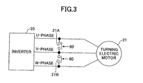
- the relays 21A and 21B are provided in the three-phase interconnection (U-phase, V-phase, and W-phase) between the inverter 20 and the turning electric motor 21 as illustrated in FIG. 3 .
- the relay 21A is provided between the U-phase and the V-phase
- the relay 21B is provided between the V-phase and the W-phase.
- the electric power generated in the state of the second regenerative operation is consumed in the internal resistor of the turning electric motor 21.
- a braking torque is generated that is determined by the resistance of the internal resistor and the rotation speed of the rotation shaft 21a of the turning electric motor 21.
- the relays 21A and 21B whose opening and closing is controlled by a main control part 60 of a turning drive control unit 40 to be described below, are opened when the driving of the turning electric motor 21 is controlled based on a speed command.
- the resolver 22 is a sensor that detects the rotation position and the rotation angle of the rotation shaft 21a of the turning electric motor 21.
- the resolver 22 is mechanically joined to the turning electric motor 21 to detect a difference between the rotation position before rotation and the rotation position after a counterclockwise rotation or a clockwise rotation of the rotation shaft 21a of the turning electric motor 21, thereby detecting the rotation angle and the rotation direction of the rotation shaft 21a.
- the rotation angle and the rotation direction of the turning mechanism 2 are derived.
- the mechanical brake 23 which is a braking device that generates a mechanical braking force, mechanically stops the rotation shaft 21a of the turning electric motor 21.
- This mechanical brake 23 is switched between braking (ON) and release (OFF) by an electromagnetic switch.
- the turning reduction machine 24 is a reduction machine that reduces the rotation speed of the rotation shaft 21a of the turning electric motor 21 and mechanically transmits it to the turning mechanism 2.
- the turning mechanism 2 is turnable with the mechanical brake 23 of the turning electric motor 21 being released, and the upper-part turning body 3 is turned counterclockwise or clockwise in this state.
- the operation apparatus 26, which is an operation apparatus for operating the turning electric motor 21, the lower-part traveling body 1, the boom 4, the arm 5, and the bucket 6, includes levers 26A and 26B and pedals 26C.
- the lever 26A which is a lever for operating the turning electric motor 21 and the arm 5, is provided near the driver's seat of the upper-part turning body 3.
- the lever 26B which is a lever for operating the boom 4 and the bucket 6, is provided near the driver's seat of the upper-part turning body 3.
- the pedals 26C which are a pair of pedals for operating the lower-part traveling body 1, are provided at the foot of the driver's seat.
- This operation apparatus 26 converts a hydraulic pressure (a primary-side hydraulic pressure) supplied through the pilot line 25 into a hydraulic pressure (a secondary-side hydraulic pressure) corresponding to the amount of operation by the operator, and outputs it.
- the secondary-side hydraulic pressure output from the operation apparatus 26 is supplied to the control valve 17 through the hydraulic line 27, and is also detected by the pressure sensor 29.
- the mechanical brake 23 is configured to be released by the controller 30 when one of the levers 26A and 26B and the pedal 26C is operated.
- the hydraulic line 27 supplies hydraulic pressures necessary for driving the hydraulic motors 1A and 1B, the boom cylinder 7, the arm cylinder 8, and the bucket cylinder 9 to the control valve 17.
- the pressure sensor 29 In the pressure sensor 29, a change in the hydraulic pressure inside the hydraulic line 28 due to the operation of the lever 26A is detected.
- the pressure sensor 29 outputs an electrical signal representing the hydraulic pressure inside the hydraulic line 28. This electrical signal is input to the controller 30.
- the controller 30, which is a control unit that controls the driving of the construction machine of the first embodiment, includes a speed command conversion part 31, a drive control unit 32, and the turning drive control unit 40.
- the controller 30 is constituted of a processor including a CPU (Central Processing Unit) and an internal memory, and the speed command conversion part 31, the drive control unit 32, and the turning drive control unit 40 are devices implemented by the CPU of the controller 30 executing a program for drive control contained in the internal memory.
- CPU Central Processing Unit
- the speed command conversion part 31 is a processing part configured to convert a signal input from the pressure sensor 29 into a speed command. Thereby, the amount of operation of the lever 26A is converted into a speed command (rad/s) for causing the turning electric motor 21 to be rotationally driven. This speed command is input to the drive control unit 32 and the turning drive control unit 40.
- the drive control unit 32 is a control unit for controlling the operation of the motor generator 12 (switching between a power running operation and a regenerative operation) and controlling the charge and discharge of the battery 19.
- This drive control unit 32 switches the power running operation and the regenerative operation of the motor generator 12 in accordance with the load state of the engine 11 and the charge state of the battery 19.
- the drive control unit 32 controls the charge and discharge of the battery 19 via the inverter 18 by switching the power running operation and the regenerative operation of the motor generator 12.
- FIG. 4 is a diagram illustrating a conversion characteristic of converting the amount of operation of the operation lever 26A into a speed command (a speed command for causing the turning electric motor 21 to rotate to cause the upper-part turning body 3 to turn) in the speed command conversion part 31 of the construction machine of the present embodiment.
- the conversion characteristic illustrated in FIG. 4 is a characteristic in the case of stopping the turning electric motor 21, and is divided into four regions, which are zero speed command regions (for counterclockwise turning and for clockwise turning), a counterclockwise turning drive region, and a clockwise turning drive region, in accordance with the amount of operation of the operation lever 26A.
- the rotation direction in which the rotation shaft 21a of the turning electric motor 21 rotates counterclockwise is referred to as "forward rotation,” and a positive sign is attached to the amount of control representing driving in the forward rotation direction.
- the rotation direction in which the rotation shaft 21a of the turning electric motor 21 rotates clockwise is referred to as “reverse rotation,” and a negative sign is attached to the amount of control representing driving in the reverse rotation direction.
- the forward rotation corresponds to the clockwise turning of the upper-part turning body 3
- the reverse rotation corresponds to the counterclockwise turning of the upper-part turning body 3.
- the zero speed command regions are regions provided in the vicinity of the neutral (within the range of ⁇ 20%) in the operating directions of the lever 26A to be used in the case of stopping the turning upper-part turning body 3.
- a zero speed command is output from the speed command conversion part 31, so that a braking torque is applied on the rotation shaft 21a of the turning electric motor 21 that is turning.
- the mechanical brake 23 is put into operation, so that the upper-part turning body 3 is kept stationary.
- the zero speed command is a speed command for causing the rotation speed of the rotation shaft 21a of the turning electric motor 21 to be zero in order to cause the turning speed of the upper-part turning body 3 to be zero, and is used as a target value for causing the rotation speed of the rotation shaft 21a to be closer to zero in PI (Proportional Integral) control to be described below.
- PI Proportional Integral
- the mechanical brake 23 is switched from a released state (OFF) to an operating state (ON) by the turning drive control unit 40 in the controller 30 when the rotation speed detected by a turning motion detection part 58 becomes zero.
- the counterclockwise turning drive region is a region where a speed command for causing the upper-part turning body 3 to turn counterclockwise is output from the speed command conversion part 31.
- the absolute value of a speed command is determined to increase in accordance with the amount of operation of the lever 26A.
- a drive command is calculated based on this speed command in the turning drive control unit 40, and the turning electric motor 21 is driven based on this drive command.
- the upper-part turning body 3 is driven to turn counterclockwise.
- the absolute value of the speed command value in the counterclockwise turning drive region is limited by a predetermined value in order to limit the turning speed of the upper-part turning body 3 to a certain value or less.
- the clockwise turning drive region is a region where a speed command for causing the upper-part turning body 3 to turn clockwise is output from the speed command conversion part 31.
- the absolute value of a speed command is determined to increase in accordance with the amount of operation of the lever 26A.
- a drive command is calculated based on this speed command in the turning drive control unit 40, and the turning electric motor 21 is driven based on this drive command.
- the upper-part turning body 3 is driven to turn clockwise.
- the absolute value of the speed command value in the clockwise turning drive region is limited by a predetermined value.
- FIG. 5 is a control block diagram illustrating a configuration of the turning drive control unit 40 of the first embodiment.
- the turning drive control unit 40 which is a control unit for controlling the driving of the turning electric motor 21 via the inverter 20, includes a drive command generation part 50 configured to generate a drive command for driving the turning electric motor 21 and the main control part 60.
- the turning drive control unit 40 calculates a drive command for controlling the driving of the turning electric motor 21 in accordance with the amount of operation of the lever 26A by executing a program for drive control contained in the internal memory of the controller 30.
- the turning drive control unit 40 controls the switching of a power running operation and a regenerative operation (first regenerative operation or second regenerative operation) and controls the charge and discharge of the battery 19 via the inverter 20 at the time of controlling the driving of the turning electric motor 21 in accordance with the amount of operation of the lever 26A.
- a speed command output from the speed command conversion part 31 in accordance with the amount of operation of the lever 26A is input to the drive command generation part 50, so that this drive command generation part 50 generates a drive command based on the speed command.
- the drive command output from the drive command generation part 50 is input to the inverter 20, and the turning electric motor 21 is AC-driven by this inverter 20 based on a PWM control signal.
- the main control part 60 is a control part configured to perform processing necessary for controlling the turning drive control unit 40. The specific contents of the processing are described at each related part.
- the turning drive control unit 40 controls the switching of a power running operation and a regenerative operation and controls the charge and discharge of the battery 19 via the inverter 20 at the time of controlling the driving of the turning electric motor 21 in accordance with the amount of operation of the operation lever 26A.
- the drive command generation part 50 includes a subtractor 51, a PI (Proportional Integral) control part 52, a torque limiting part 53, a torque limiting part 54, a subtractor 55, a PI control part 56, a current conversion part 57, and the turning motion detection part 58.
- a speed command (rad/s) for turning drive according to the amount of operation of the lever 26A is input to the subtractor 51 of this drive command generation part 50.
- the subtractor 51 subtracts the rotation speed (rad/s) of the turning electric motor 21 detected by the turning motion detection part 58 from the value of a speed command (hereinafter, speed command value) according to the amount of operation of the lever 26A, and outputs a deviation. This deviation is used for PI control for causing the rotation speed of the turning electric motor 21 to be closer to the speed command value (target value) in the PI control part 52 to be described below.
- the PI control part 52 performs PI control based on the deviation input from the subtractor 51 so as to cause the rotation speed of the turning electric motor 21 to be closer to the speed command value (target value) (that is, so as to decrease this deviation), and calculates a torque current command necessary therefor.
- the generated torque current command is input to the torque limiting part 53.
- the torque limiting part 53 performs the process of limiting the value of the torque current command (hereinafter, torque current command value) in accordance with the amount of operation of the lever 26A. This limiting process is performed based on the limitation characteristic of a slow increase in the allowable value of the torque current command value in accordance with the amount of operation of the lever 26A. An abrupt increase in the torque current command value calculated by the PI control part 52 degrades controllability. Therefore, such limiting of the torque current command value is performed in order to prevent this.
- the limitation characteristic of the torque limiting part 53 is contained in the internal memory of the main control part 60.
- the main control part 60 reads the limitation characteristic in the internal memory, and inputs it to the torque limiting part 53.
- This limitation characteristic has a characteristic to slowly increase (the absolute value of) the allowable value of the torque current command value with an increase in the amount of operation of the lever 26A, and has a characteristic for limiting both the clockwise direction and the counterclockwise direction of the upper-part turning body 3.
- Data showing the limitation characteristic are stored in the internal memory of the main control part 60, and are read by the torque limiting part 53.
- the torque limiting part 54 limits the torque current command value input from the torque limiting part 53 so that a torque generated by the torque current command input from the torque limiting part 53 is less than or equal to the maximum allowable torque value of the turning electric motor 21. This limitation of the torque current command value is performed on both the clockwise rotation and the counterclockwise rotation of the upper-part turning body 3 the same as in the torque limiting part 53.
- the upper limit value (maximum value for clockwise turning) and the lower limit value (minimum value for counterclockwise turning) of the allowable value for limiting the torque current command value in the torque limiting part 54 are set to such values as to enable generation of drive torque for turning the boom 4, the arm 5, and the bucket 6 to the upper side of a slope even in the state where the upper-part turning body 3 on the slope has a large inertia moment with the boom 4, the arm 5 and the bucket 6 being extended even if the torque current command value is limited by the torque limiting part 54.
- the allowable value of the torque limiting part 54 is contained in the internal memory of the main control part 60, and the main control part 60 reads the allowable value in the internal memory and inputs it to the torque limiting part 54.
- the subtractor 55 outputs a deviation obtained by subtracting the output value of the current conversion part 57 from the torque current command value input from the torque limiting part 54. This deviation is used in PI control for causing the drive torque of the turning electric motor 21 output from the current conversion part 57 to be closer to torque represented by the torque current command value (target value) input via the torque limiting part 54 in a feedback loop including the PI control part 56 and the current conversion part 57 described below.
- the PI control part 56 based on the deviation input from the subtractor 55, performs PI control to reduce this deviation and generates a voltage command to become a final drive command to be sent to the inverter 20.
- the inverter 20 PWM-drives the turning electric motor 21 based on the torque current command input from the PI control part 56.
- the current conversion part 57 detects the motor current of the turning electric motor 21, converts this into a value corresponding to the torque current command, and inputs it to the subtractor 55.
- the turning motion detection part 58 detects a change in the rotation position of the turning electric motor 21 detected by the resolver 22 (that is, the rotation of the upper-part turning body 3), and derives the rotation speed of the turning electric motor 21 from a temporal change in the rotation position through a differential operation. Data representing the derived rotation speed are input to the subtractor 51 and the main control part 60.
- a torque current command for driving the turning electric motor 21 is generated based on the speed command input from the speed command conversion part 31, so that the upper-part turning body 3 is caused to turn at a desired speed.
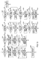
- FIG. 6 is a chart illustrating a procedure for controlling the driving of the turning electric motor 21 by the main control part 60 of the turning drive control unit 40 of the first embodiment.
- the main control part 60 uses a clockwise turning flag and a counterclockwise turning flag showing that the upper-part turning body 3 is turning clockwise and counterclockwise.
- the clockwise turning flag shows the presence or absence of the "forward rotation,” or the counterclockwise rotation of the rotation shaft 21a of the turning electric motor 21, and the counterclockwise turning flag shows the presence or absence of the "reverse rotation,” or the clockwise rotation of the rotation shaft 21a of the turning electric motor 21.
- main control part 60 includes a timer for counting elapsed time in steps S124 through S126 and S134 through S136 to be described below.
- step S100 The process illustrated in FIG. 6 starts at (1), and the process of step S100 is first executed.
- the main control part 60 determines whether the value of a speed command is positive (step S100).
- the speed command is input to the main control part 60 from the speed command conversion part 31. Therefore, this process is a process executed by determining whether the value of the speed command input to the main control part 60 from the speed command conversion part 31 is positive.
- step S101 If determining that the value of the speed command is positive, the main control part 60 sets both the clockwise turning flag and the counterclockwise turning flag to "0" (step S101). This is for resetting both flags.
- the main control part 60 determines whether a rotation speed is positive (step S102). If determining that the rotation speed is positive, the main control part 60 sets the clockwise turning flag to "1" and sets the counterclockwise turning flag to "0" (step S103). This is because in this case, the rotation shaft 21a of the turning electric motor 21 is in forward rotation so that the upper-part turning body 3 is turning clockwise.
- the main control part 60 causes the turning drive control unit 40 to control the driving of the turning electric motor 21 in accordance with the speed command output from the speed command conversion part 31 (step S150). Thereby, the upper-part turning body 3 is caused to turn clockwise.
- step S150 the procedure proceeds to step S150, and the main control part 60 causes the turning drive control unit 40 to control the driving of the turning electric motor 21 in accordance with the speed command output from the speed command conversion part 31 (step S150).
- step S150 the rotation speed of the rotation shaft 21a of the turning electric motor 21 is zero or negative although a speed command for forward rotation has been output from the speed command conversion part 31, and specifically, corresponds to the case where the upper-part turning body 3 is stationary or being caused to turn counterclockwise by an external force although the operation lever 26A is being operated in the direction of clockwise turning.
- step S110 the main control part 60 determines whether the speed command is negative (step S110).
- the speed command is input to the main control part 60 from the speed command conversion part 31. Therefore, this process is a process executed by determining whether the value of the speed command input to the main control part 60 from the speed command conversion part 31 is negative.
- step S111 If determining that the value of the speed command is negative, the main control part 60 sets both the clockwise turning flag and the counterclockwise turning flag to "0" (step S111). This is for resetting both flags.
- the main control part 60 determines whether a rotation speed is negative (step S112). If determining that the rotation speed is negative, the main control part 60 sets the clockwise turning flag to "0" and sets the counterclockwise turning flag to "1" (step S113). This is because in this case, the rotation shaft 21a of the turning electric motor 21 is in reverse rotation so that the upper-part turning body 3 is turning counterclockwise.
- the main control part 60 causes the turning drive control unit 40 to control the driving of the turning electric motor 21 in accordance with the speed command output from the speed command conversion part 31 (step S150). Thereby, the upper-part turning body 3 is caused to turn counterclockwise.
- step S150 the procedure proceeds to step S150, and the main control part 60 causes the turning drive control unit 40 to control the driving of the turning electric motor 21 in accordance with the speed command output from the speed command conversion part 31 (step S150).
- step S150 the rotation speed of the rotation shaft 21a of the turning electric motor 21 is zero or positive although a speed command for reverse rotation has been output from the speed command conversion part 31, and specifically, corresponds to the case where the upper-part turning body 3 is stationary or being caused to turn clockwise by an external force although the operation lever 26A is being operated in the direction of counterclockwise turning.
- step S110 determines whether the speed command is not negative.
- step S120 determines whether the clockwise turning flag is "1" (step S120). This is for determining whether the upper-part turning body 3 is turning clockwise (the rotation shaft 21a of the turning electric motor 21 is in forward rotation) with the speed command being zero. This corresponds to, for example, the case where the amount of operation of the lever 26A is in the zero speed command region in order to come to a stop from a clockwise turning state.
- the main control part 60 determines whether a rotation speed is lower than a predetermined set speed (S121).
- the predetermined set speed is extremely low, and is set to, for example, a 10% speed. This is for determining whether the state is immediately before a stop of rotation.
- the 10% speed is a rotation speed in the case of the highest turning speed being a 100% speed.
- the main control part 60 closes the relays 21A and 21B to short-circuit the turning electric motor 21 (step S122). This is for stopping the rotation shaft 21a with rotational resistance due to a second regenerative operation by causing the turning electric motor 21 to perform the second regenerative operation by short-circuiting its three-phase interconnection in the case of determining that the rotation is immediately before coming to a stop.
- step S123 the main control part 60 determines whether or not the rotation speed is less than or equal to zero. This is for determining whether or not the rotation shaft 21a has stopped or reversed.
- the main control part 60 sets a timer (step S124). This is for preparing for counting elapsed time.
- the timer is set to 0.1 seconds.
- the main control part 60 starts counting elapsed time with the timer (step S125). This is for making a determination for canceling the short-circuited state based on the elapsed time.
- the main control part 60 determines whether the counting is up (step S126). This process of step S126 is repeatedly performed until it is determined that the counting is up.
- step S127 the main control part 60 sets the clockwise turning flag to "0" (step S127). This is because it is believed that the rotation shaft 21a has come to a stop with the rotational resistance due to the second regenerative operation as a result of causing the turning electric motor 21 to perform the second regenerative operation by short-circuiting its three-phase interconnection only for 0.1 seconds.
- the main control part 60 causes the turning drive control unit 40 to control the driving of the turning electric motor 21 in accordance with the speed command output from the speed command conversion part 31 (step S150).
- the speed command is a zero speed command. Therefore, a braking torque is applied on the rotation shaft 21a of the turning electric motor 21, so that the rotation speed of the rotation shaft 21a is controlled to be zero. Thereby, the upper-part turning body 3 is stopped. Therefore, the mechanical brake 23 is put into operation, so that the upper-part turning body 3 is kept stationary.
- step S150 the procedure proceeds to step S150, and the main control part 60 causes the turning drive control unit 40 to control the driving of the turning electric motor 21 in accordance with the speed command output from the speed command conversion part 31 (step S150).
- step S150 This is the state where a zero speed command has been output from the speed command conversion part 31 so that a braking torque is applied on the rotation shaft 21a of the turning electric motor 21 while the rotation speed during the clockwise turning is more than or equal to the set value. This corresponds to such a time as is immediately after a release of the lever 26A during the clockwise turning.
- step S123 if it is determined in step S123 that the rotation speed is not less than or equal to zero (that is, the rotation speed is positive), the procedure proceeds to step S100, and the procedure is repeatedly performed.
- step S130 the main control part 60 determines whether the counterclockwise turning flag is "1" (step S130). This is for determining whether the upper-part turning body 3 is turning counterclockwise (the rotation shaft 21a of the turning electric motor 21 is in reverse rotation) with the speed command being zero. This corresponds to, for example, the case where the amount of operation of the lever 26A is in the zero speed command region in order to come to a stop from a counterclockwise turning state.
- the main control part 60 determines whether a rotation speed is higher than a predetermined negative set speed (S131).
- the predetermined set speed is extremely low, and is set to, for example, a -10% speed. This is for determining whether the state is immediately before a stop of rotation.
- the -10% speed is a rotation speed in the case of the highest turning speed in the reverse rotation direction being a -100% speed.
- the main control part 60 closes the relays 21A and 21B to short-circuit the turning electric motor 21 (step S132). This is for stopping the rotation shaft 21a with rotational resistance due to a second regenerative operation by causing the turning electric motor 21 to perform the second regenerative operation by short-circuiting its three-phase interconnection in the case of determining that the rotation is immediately before coming to a stop.
- step S133 the main control part 60 determines whether or not the rotation speed is more than or equal to zero. This is for determining whether or not the rotation shaft 21a has stopped or reversed.
- the main control part 60 sets a timer (step S134). This is for preparing for counting elapsed time.
- the timer is set to 0.1 seconds.
- the main control part 60 starts a countdown of elapsed time with the timer (step S135). This is for counting elapsed time.
- the main control part 60 determines whether the counting is up (step S136). This process of step S136 is repeatedly performed until it is determined that the counting is up.
- step S137 the main control part 60 sets the counterclockwise turning flag to "0" (step S137). This is because it is believed that the rotation shaft 21a has come to a stop with the rotational resistance due to the second regenerative operation as a result of causing the turning electric motor 21 to perform the second regenerative operation by short-circuiting its three-phase interconnection only for 0.1 seconds.
- the main control part 60 causes the turning drive control unit 40 to control the driving of the turning electric motor 21 in accordance with the speed command output from the speed command conversion part 31 (step S150).
- the speed command is a zero speed command. Therefore, a braking torque is applied on the rotation shaft 21a of the turning electric motor 21, so that the rotation speed of the rotation shaft 21a is controlled to be zero. Thereby, the upper-part turning body 3 is stopped. Therefore, the mechanical brake 23 is put into operation, so that the upper-part turning body 3 is kept stationary.
- step S130 If it is determined in step S130 that the counterclockwise turning flag is not "1," the procedure proceeds to step S150, and the main control part 60 causes the turning drive control unit 40 to control the driving of the turning electric motor 21 in accordance with the speed command output from the speed command conversion part 31 (step S150). This is for causing a stopped state due to a zero speed command or a stopped state due to the mechanical brake 23 to be kept by the drive control of the turning drive control unit 40 because turning is stopped.
- step S150 the procedure proceeds to step S150, and the main control part 60 causes the turning drive control unit 40 to control the driving of the turning electric motor 21 in accordance with the speed command output from the speed command conversion part 31 (step S150).
- step S150 This is the state where a zero speed command has been output from the speed command conversion part 31 so that a braking torque is applied on the rotation shaft 21a of the turning electric motor 21 while the rotation speed during the counterclockwise turning is less than or equal to the set value. This corresponds to such a time as is immediately after a release of the lever 26A during the counterclockwise turning.
- step S133 determines whether the rotation speed is not more than or equal to zero (that is, the rotation speed is negative). If it is determined in step S133 that the rotation speed is not more than or equal to zero (that is, the rotation speed is negative), the procedure proceeds to step S100, and the procedure is repeatedly performed.
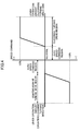
- FIG. 7 is a characteristics chart for illustrating an operation at a time when turning is stopped by the drive control of the turning drive control unit 40 of the first embodiment. These characteristics indicate temporal changes in a speed command, a turning speed, and a drive torque (braking torque) at a time when the upper-part turning body 3 comes to a stop from a clockwise turning state.
- the main control part 60 closes the relays 21A and 21B so that the turning electric motor 21 is short-circuited. Thereby, a rotational resistance due to a second regenerative operation is generated at the rotation shaft 21a of the turning electric motor 21, so that the rotation speed of the rotation shaft 21a (turning speed) gradually decreases.
- This state is realized by the drive control process by step S122 illustrated in FIG. 6 .
- the main control part 60 sets a timer and starts a countdown. This state is realized by the process by steps S123 through S125 illustrated in FIG. 6 .
- the main control part 60 opens the relays 21A and 21B, and causes the turning drive control unit 40 to execute drive control based on a zero speed command. This is realized by the process by steps S126, S127, and S150 illustrated in FIG. 6 .
- the turning drive control unit 40 of the first embodiment by short-circuiting the turning electric motor 21 immediately before a stop of rotation, it is possible to stop the rotation shaft 21a of the turning electric motor 21 with the rotational resistance force of a regenerative operation (second regenerative operation).
- the rotational resistance force applied on the rotation shaft 21a at the time of this stop is extremely small and its temporal change is slow compared with the braking torque applied on the rotation shaft 21a by drive control based on a speed command without short-circuiting as in the conventional way. Therefore, immediately before a stop of rotation, it is possible to cause the braking torque of the turning electric motor 21 to be smaller than before the time immediately before the stop of rotation.
- the turning electric motor 21 is an AC motor PWM-driven by the inverter 20, and the resolver 22 and the turning motion detection part 58 are used to detect its rotation speed.
- the turning electric motor 21 may be a DC motor.
- the inverter 20, the resolver 22, and the turning motion detection part 58 are unnecessary, and a value detected with the tachogenerator of the DC motor may be used as the rotation speed.
- the above description is given using a hybrid construction machine.
- the construction machine to which to apply the turning drive unit of the first embodiment is not limited to a hybrid type as long as the construction machine has a motorized turning mechanism.
- FIG. 8 is a block diagram illustrating a configuration of the turning drive control unit 40 of a second embodiment.
- the turning drive control unit 40 of the second embodiment is different from the turning drive control unit 40 of the first embodiment in not including the relays 21A and 21B, but otherwise, is based on the turning drive control unit 40 of the first embodiment in configuration. Therefore, the same components are given the same characters and their description is omitted.
- the main control part 60 of the second embodiment stops the inverter 20 only for a predetermined short period of time immediately before stopping the rotation shaft 21a of the turning electric motor 21. A description is given below of a procedure using FIG. 9 .
- FIG. 9 is a chart illustrating a procedure for controlling the driving of the turning electric motor 21 by the main control part 60 of the turning drive control unit 40 of the second embodiment.
- the main control part 60 uses a clockwise turning flag and a counterclockwise turning flag showing that the upper-part turning body 3 is turning clockwise and counterclockwise.
- the clockwise turning flag shows the presence or absence of the "forward rotation,” or the counterclockwise rotation of the rotation shaft 21a of the turning electric motor 21, and the counterclockwise turning flag shows the presence or absence of the "reverse rotation,” or the clockwise rotation of the rotation shaft 21a of the turning electric motor 21.
- the main control part 60 includes a timer for counting elapsed time in steps S223 through S225 and S233 through S235 to be described below.
- step S200 starts at (1), and the process of step S200 is first executed.
- the main control part 60 determines whether the value of a speed command is positive (step S200).
- the speed command is input to the main control part 60 from the speed command conversion part 31. Therefore, this process is a process executed by determining whether the value of the speed command input to the main control part 60 from the speed command conversion part 31 is positive.
- the main control part 60 sets both the clockwise turning flag and the counterclockwise turning flag to "0" (step S201). This is for resetting both flags.
- the main control part 60 determines whether a rotation speed is positive (step S202). If determining that the rotation speed is positive, the main control part 60 sets the clockwise turning flag to "1" and sets the counterclockwise turning flag to "0" (step S203). This is because in this case, the rotation shaft 21a of the turning electric motor 21 is in forward rotation so that the upper-part turning body 3 is turning clockwise.
- the main control part 60 causes the turning drive control unit 40 to control the driving of the turning electric motor 21 in accordance with the speed command output from the speed command conversion part 31 (step S250). Thereby, the upper-part turning body 3 is caused to turn clockwise.
- step S250 the procedure proceeds to step S250, and the main control part 60 causes the turning drive control unit 40 to control the driving of the turning electric motor 21 in accordance with the speed command output from the speed command conversion part 31 (step S250).
- the rotation speed of the rotation shaft 21a of the turning electric motor 21 is zero or negative although a speed command for forward rotation has been output from the speed command conversion part 31, and specifically, corresponds to the case where the upper-part turning body 3 is stationary or being caused to turn counterclockwise by an external force although the operation lever 26A is being operated in the direction of clockwise turning.
- step S210 the main control part 60 determines whether the speed command is negative.
- the speed command is input to the main control part 60 from the speed command conversion part 31. Therefore, this process is a process executed by determining whether the value of the speed command input to the main control part 60 from the speed command conversion part 31 is negative.
- the main control part 60 sets both the clockwise turning flag and the counterclockwise turning flag to "0" (step S211). This is for resetting both flags.
- the main control part 60 determines whether a rotation speed is negative (step S212). If determining that the rotation speed is negative, the main control part 60 sets the clockwise turning flag to "0" and sets the counterclockwise turning flag to "1" (step S213). This is because in this case, the rotation shaft 21a of the turning electric motor 21 is in reverse rotation so that the upper-part turning body 3 is turning counterclockwise.
- the main control part 60 causes the turning drive control unit 40 to control the driving of the turning electric motor 21 in accordance with the speed command output from the speed command conversion part 31 (step S250). Thereby, the upper-part turning body 3 is caused to turn counterclockwise.
- step S250 the procedure proceeds to step S250, and the main control part 60 causes the turning drive control unit 40 to control the driving of the turning electric motor 21 in accordance with the speed command output from the speed command conversion part 31 (step S250).
- the rotation speed of the rotation shaft 21a of the turning electric motor 21 is zero or positive although a speed command for reverse rotation has been output from the speed command conversion part 31, and specifically, corresponds to the case where the upper-part turning body 3 is stationary or being caused to turn clockwise by an external force although the operation lever 26A is being operated in the direction of counterclockwise turning.
- step S210 determines whether the speed command is not negative. This is for determining whether the upper-part turning body 3 is turning clockwise (the rotation shaft 21a of the turning electric motor 21 is in forward rotation) with the speed command being zero. This corresponds to, for example, the case where the amount of operation of the lever 26A is in the zero speed command region in order to come to a stop from a clockwise turning state.
- the main control part 60 determines whether a rotation speed is lower than a predetermined set speed (S221).
- the predetermined set speed is extremely low, and is set to, for example, a 5% speed. This is for determining whether the state is immediately before a stop of rotation.
- the 5% speed is a rotation speed in the case of the highest turning speed being a 100% speed.
- step S222 the main control part 60 stops the inverter 20 (step S222). This is for causing a braking torque immediately before a stop of rotation to be smaller than before the time immediately before the stop of rotation by freeing the rotation shaft 21a by causing a torque current command value for driving the turning electric motor 21 to be zero in the case of determining that the rotation is immediately before coming to a stop.
- the main control part 60 sets a timer (step S223). This is for preparing for counting elapsed time.
- the timer is set to 0.1 seconds.
- step S224 the main control part 60 starts counting elapsed time with the timer. This is for making a determination for returning the allowable value of the torque limiting part 54 based on the elapsed time.
- the main control part 60 determines whether the counting is up (step S225). This process of step S225 is repeatedly performed until it is determined that the counting is up.
- the main control part 60 sets the clockwise turning flag to "0" (step S226). This is because it is believed that the rotation shaft 21a has come to a stop with the rotational resistance of the turning mechanism 2 and the turning electric motor 21 as a result of freeing the rotation shaft 21a by stopping the inverter 20 for driving the turning electric motor 21 only for 0.1 seconds.
- the main control part 60 causes the turning drive control unit 40 to control the driving of the turning electric motor 21 in accordance with the speed command output from the speed command conversion part 31 (step S250).
- the speed command is a zero speed command. Therefore, a braking torque is applied on the rotation shaft 21a of the turning electric motor 21, so that the rotation speed of the rotation shaft 21a is controlled to be zero. Thereby, the upper-part turning body 3 is stopped. Therefore, the mechanical brake 23 is put into operation, so that the upper-part turning body 3 is kept stationary.
- step S250 the procedure proceeds to step S250, and the main control part 60 causes the turning drive control unit 40 to control the driving of the turning electric motor 21 in accordance with the speed command output from the speed command conversion part 31 (step S250).
- step S250 This is the state where a zero speed command has been output from the speed command conversion part 31 so that a braking torque is applied on the rotation shaft 21a of the turning electric motor 21 while the rotation speed during the clockwise turning is more than or equal to the set value. This corresponds to such a time as is immediately after a release of the lever 26A during the clockwise turning.
- step S230 the main control part 60 determines whether the counterclockwise turning flag is "1" (step S230). This is for determining whether the upper-part turning body 3 is turning counterclockwise (the rotation shaft 21a of the turning electric motor 21 is in reverse rotation) with the speed command being zero. This corresponds to, for example, the case where the amount of operation of the lever 26A is in the zero speed command region in order to come to a stop from a counterclockwise turning state.
- the main control part 60 determines whether a rotation speed is higher than a predetermined negative set speed (S231).
- the predetermined set speed is extremely low, and is set to, for example, a -5% speed. This is for determining whether the state is immediately before a stop of rotation.
- the -5% speed is a rotation speed in the case of the highest turning speed in the reverse rotation direction being a -100% speed.
- the main control part 60 causes the allowable value of the torque limiting part 54 to be zero (step S232). This is for causing a braking torque immediately before a stop of rotation to be smaller than before the time immediately before the stop of rotation by freeing the rotation shaft 21a by causing a torque current command value for driving the turning electric motor 21 to be zero in the case of determining that the rotation is immediately before coming to a stop.
- the main control part 60 sets a timer (step S233). This is for preparing for counting elapsed time.
- the timer is set to 0.1 seconds.
- the main control part 60 starts a countdown of elapsed time with the timer (step S234). This is for counting elapsed time.
- the main control part 60 determines whether the counting is up (step S235). This process of step S235 is repeatedly performed until it is determined that the counting is up.
- the main control part 60 sets the counterclockwise turning flag to "0" (step S236). This is because it is believed that the rotation shaft 21a has come to a stop with the rotational resistance of the turning mechanism 2 and the turning electric motor 21 as a result of freeing the rotation shaft 21a by stopping the inverter 20 for driving the turning electric motor 21 only for 0.1 seconds.
- the main control part 60 causes the turning drive control unit 40 to control the driving of the turning electric motor 21 in accordance with the speed command output from the speed command conversion part 31 (step S250).
- the speed command is a zero speed command. Therefore, a braking torque is applied on the rotation shaft 21a of the turning electric motor 21, so that the rotation speed of the rotation shaft 21a is controlled to be zero. Thereby, the upper-part turning body 3 is stopped. Therefore, the mechanical brake 23 is put into operation, so that the upper-part turning body 3 is kept stationary.
- step S230 If it is determined in step S230 that the counterclockwise turning flag is not "1," the procedure proceeds to step S250, and the main control part 60 causes the turning drive control unit 40 to control the driving of the turning electric motor 21 in accordance with the speed command output from the speed command conversion part 31 (step S250). This is for causing a stopped state due to a zero speed command or a stopped state due to the mechanical brake 23 to be kept by the drive control of the turning drive control unit 40 because turning is stopped.
- step S250 the procedure proceeds to step S250, and the main control part 60 causes the turning drive control unit 40 to control the driving of the turning electric motor 21 in accordance with the speed command output from the speed command conversion part 31 (step S250).
- step S250 This is the state where a zero speed command has been output from the speed command conversion part 31 so that a braking torque is applied on the rotation shaft 21a of the turning electric motor 21 while the rotation speed during the counterclockwise turning is less than or equal to the set value. This corresponds to such a time as is immediately after a release of the lever 26A during the counterclockwise turning.
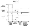
- FIG. 10 is a characteristics chart for illustrating an operation at a time when turning is stopped by the drive control of the turning drive control unit 40 of the second embodiment. These characteristics indicate temporal changes in a speed command, a turning speed, and a drive torque (braking torque) at a time when the upper-part turning body 3 comes to a stop from a clockwise turning state.
- the main control part 60 sets a timer and starts a countdown. This state is realized by the process by steps S223 and S224 illustrated in FIG. 9 .
- the main control part 60 causes the turning drive control unit 40 to execute drive control based on a zero speed command. This is realized by the process by steps S225, S226, and S250 illustrated in FIG. 9 .
- the turning drive control unit 40 of the second embodiment by turning off drive control of the driving of the turning electric motor 21 for an extremely short period of time (here, 0.1 seconds) immediately before a stop of rotation, it is possible to gradually reduce the rotation speed of the rotation shaft 21a and stop the rotation shaft 21a with the rotational resistance of the turning electric motor 21 and the turning mechanism 2.
- the rotational resistance force applied on the rotation shaft 21a at the time of this stop is extremely small and its temporal change is slow compared with the braking torque applied on the rotation shaft 21a by drive control based on a speed command without turning off the drive control as in the conventional way. Therefore, it is possible to cause the braking torque of the turning electric motor 21 to be smaller than before the time immediately before the stop of rotation.
- the turning drive control unit 40 of a third embodiment is configured to be capable of changing an allowable value input to the torque limiting part 54, but otherwise, is based on the turning drive control unit 40 of the second embodiment in configuration. Therefore, the same components are given the same characters referring to FIG. 8 , and their description is omitted.
- the main control part 60 of the third embodiment causes the value of a torque current command to be a 20% value of its maximum value for a predetermined short period of time immediately before stopping the rotation shaft 21a of the turning electric motor 21. A description is given below of a procedure using FIG. 11 .
- FIG. 11 is a chart illustrating a procedure for controlling the driving of the turning electric motor 21 by the main control part 60 of the turning drive control unit 40 of the third embodiment.
- the main control part 60 uses a clockwise turning flag and a counterclockwise turning flag showing that the upper-part turning body 3 is turning clockwise and counterclockwise.
- the clockwise turning flag shows the presence or absence of the "forward rotation,” or the counterclockwise rotation of the rotation shaft 21a of the turning electric motor 21, and the counterclockwise turning flag shows the presence or absence of the "reverse rotation,” or the clockwise rotation of the rotation shaft 21a of the turning electric motor 21.
- step S300 starts at (1), and the process of step S300 is first executed.
- the main control part 60 determines whether the value of a speed command is positive (step S300).
- the speed command is input to the main control part 60 from the speed command conversion part 31. Therefore, this process is a process executed by determining whether the value of the speed command input to the main control part 60 from the speed command conversion part 31 is positive.
- the main control part 60 sets both the clockwise turning flag and the counterclockwise turning flag to "0" (step S301). This is for resetting both flags.
- the main control part 60 determines whether a rotation speed is positive (step S302). If determining that the rotation speed is positive, the main control part 60 sets the clockwise turning flag to "1" and sets the counterclockwise turning flag to "0" (step S303). This is because in this case, the rotation shaft 21a of the turning electric motor 21 is in forward rotation so that the upper-part turning body 3 is turning clockwise.
- the main control part 60 causes the turning drive control unit 40 to control the driving of the turning electric motor 21 in accordance with the speed command output from the speed command conversion part 31 (step S350). Thereby, the upper-part turning body 3 is caused to turn clockwise.
- step S350 the procedure proceeds to step S350, and the main control part 60 causes the turning drive control unit 40 to control the driving of the turning electric motor 21 in accordance with the speed command output from the speed command conversion part 31 (step S350).
- step S350 the rotation speed of the rotation shaft 21a of the turning electric motor 21 is zero or negative although a speed command for forward rotation has been output from the speed command conversion part 31, and specifically, corresponds to the case where the upper-part turning body 3 is stationary or being caused to turn counterclockwise by an external force although the operation lever 26A is being operated in the direction of clockwise turning.
- step S310 the main control part 60 determines whether the speed command is negative.
- the speed command is input to the main control part 60 from the speed command conversion part 31. Therefore, this process is a process executed by determining whether the value of the speed command input to the main control part 60 from the speed command conversion part 31 is negative.
- step S311 If determining that the value of the speed command is negative, the main control part 60 sets both the clockwise turning flag and the counterclockwise turning flag to "0" (step S311). This is for resetting both flags.
- the main control part 60 determines whether a rotation speed is negative (step S312). If determining that the rotation speed is negative, the main control part 60 sets the clockwise turning flag to "0" and sets the counterclockwise turning flag to "1" (step S313). This is because in this case, the rotation shaft 21a of the turning electric motor 21 is in reverse rotation so that the upper-part turning body 3 is turning counterclockwise.
- the main control part 60 causes the turning drive control unit 40 to control the driving of the turning electric motor 21 in accordance with the speed command output from the speed command conversion part 31 (step S350). Thereby, the upper-part turning body 3 is caused to turn counterclockwise.
- step S350 the procedure proceeds to step S350, and the main control part 60 causes the turning drive control unit 40 to control the driving of the turning electric motor 21 in accordance with the speed command output from the speed command conversion part 31 (step S350).
- step S350 the rotation speed of the rotation shaft 21a of the turning electric motor 21 is zero or positive although a speed command for reverse rotation has been output from the speed command conversion part 31, and specifically, corresponds to the case where the upper-part turning body 3 is stationary or being caused to turn clockwise by an external force although the operation lever 26A is being operated in the direction of counterclockwise turning.
- step S320 determines whether the clockwise turning flag is "1" (step S320). This is for determining whether the upper-part turning body 3 is turning clockwise (the rotation shaft 21a of the turning electric motor 21 is in forward rotation) with the speed command being zero. This corresponds to, for example, the case where the amount of operation of the lever 26A is in the zero speed command region in order to come to a stop from a clockwise turning state.
- the main control part 60 determines whether a rotation speed is lower than a predetermined set speed (S321).
- the predetermined set speed is extremely low, and is set to, for example, a 10% speed. This is for determining whether the state is immediately before a stop of rotation.
- the 10% speed is a rotation speed in the case of the highest turning speed being a 100% speed.
- the main control part 60 causes the allowable value of the torque limiting part 54 to be value T2, which is 20% of the maximum allowable value (step S322). This is for causing a braking torque immediately before a stop of rotation to be smaller than before the time immediately before the stop of rotation by reducing a torque current command value for driving the turning electric motor 21 in the case of determining that the rotation is immediately before coming to a stop.
- step S323 the main control part 60 determines whether or not the rotation speed is less than or equal to zero. This is for determining whether or not the rotation shaft 21a has stopped or reversed.
- step S324 If determining that the rotation speed is less than or equal to zero, the main control part 60 sets the clockwise turning flag to "0" (step S324). This is because the turning electric motor 21 has stopped.
- the main control part 60 causes the turning drive control unit 40 to control the driving of the turning electric motor 21 in accordance with the speed command output from the speed command conversion part 31 (step S350).
- the speed command is a zero speed command. Therefore, a braking torque is applied on the rotation shaft 21a of the turning electric motor 21, so that the rotation speed of the rotation shaft 21a is controlled to be zero. Thereby, the upper-part turning body 3 is stopped. Therefore, the mechanical brake 23 is put into operation, so that the upper-part turning body 3 is kept stationary.
- step S350 the procedure proceeds to step S350, and the main control part 60 causes the turning drive control unit 40 to control the driving of the turning electric motor 21 in accordance with the speed command output from the speed command conversion part 31 (step S350).
- step S350 This is the state where a zero speed command has been output from the speed command conversion part 31 so that a braking torque is applied on the rotation shaft 21a of the turning electric motor 21 while the rotation speed during the clockwise turning is more than or equal to the set value. This corresponds to such a time as is immediately after a release of the lever 26A during the clockwise turning.
- step S323 determines whether the rotation speed is less than or equal to zero (that is, the rotation speed is positive). If it is determined in step S323 that the rotation speed is not less than or equal to zero (that is, the rotation speed is positive), the procedure proceeds to step S300, and the procedure is repeatedly performed.
- step S330 the main control part 60 determines whether the counterclockwise turning flag is "1" (step S330). This is for determining whether the upper-part turning body 3 is turning counterclockwise (the rotation shaft 21a of the turning electric motor 21 is in reverse rotation) with the speed command being zero. This corresponds to, for example, the case where the amount of operation of the lever 26A is in the zero speed command region in order to come to a stop from a counterclockwise turning state.
- the main control part 60 determines whether a rotation speed is higher than a predetermined negative set speed (S331).
- the predetermined set speed is extremely low, and is set to, for example, a -10% speed. This is for determining whether the state is immediately before a stop of rotation.
- the -10% speed is a rotation speed in the case of the highest turning speed in the reverse rotation direction being a -100% speed.
- the main control part 60 causes the allowable value of the torque limiting part 54 to be value T2, which is 20% of the maximum allowable value (step S332). This is for causing a braking torque immediately before a stop of rotation to be smaller than before the time immediately before the stop of rotation by reducing a torque current command value for driving the turning electric motor 21 in the case of determining that the rotation is immediately before coming to a stop.
- step S333 the main control part 60 determines whether or not the rotation speed is more than or equal to zero. This is for determining whether or not the rotation shaft 21a has stopped or reversed.
- step S334 If determining that the rotation speed is more than or equal to zero, the main control part 60 sets the counterclockwise turning flag to "0" (step S334). This is because the turning electric motor 21 has stopped.
- the main control part 60 causes the turning drive control unit 40 to control the driving of the turning electric motor 21 in accordance with the speed command output from the speed command conversion part 31 (step S350).
- the speed command is a zero speed command. Therefore, a braking torque is applied on the rotation shaft 21a of the turning electric motor 21, so that the rotation speed of the rotation shaft 21a is controlled to be zero. Thereby, the upper-part turning body 3 is stopped. Therefore, the mechanical brake 23 is put into operation, so that the upper-part turning body 3 is kept stationary.
- step S330 If it is determined in step S330 that the counterclockwise turning flag is not "1," the procedure proceeds to step S350, and the main control part 60 causes the turning drive control unit 40 to control the driving of the turning electric motor 21 in accordance with the speed command output from the speed command conversion part 31 (step S350). This is for causing a stopped state due to a zero speed command or a stopped state due to the mechanical brake 23 to be kept by the drive control of the turning drive control unit 40 because turning is stopped.
- step S350 the procedure proceeds to step S350, and the main control part 60 causes the turning drive control unit 40 to control the driving of the turning electric motor 21 in accordance with the speed command output from the speed command conversion part 31 (step S350).
- step S350 This is the state where a zero speed command has been output from the speed command conversion part 31 so that a braking torque is applied on the rotation shaft 21a of the turning electric motor 21 while the rotation speed during the counterclockwise turning is less than or equal to the set value. This corresponds to such a time as is immediately after a release of the lever 26A during the counterclockwise turning.
- step S333 determines whether the rotation speed is not more than or equal to zero (that is, the rotation speed is negative). If it is determined in step S333 that the rotation speed is not more than or equal to zero (that is, the rotation speed is negative), the procedure proceeds to step S300, and the procedure is repeatedly performed.
- FIG. 12 is a characteristics chart for illustrating an operation at a time when turning is stopped by the drive control of the turning drive control unit 40 of the third embodiment. These characteristics indicate temporal changes in a speed command, a turning speed, and a drive torque (braking torque) at a time when the upper-part turning body 3 comes to a stop from a clockwise turning state.
- the main control part 60 sets the allowable value of the torque limiting part 54 to "-T2.” Thereby, the rotation speed (turning speed) is gradually reduced with a reduced braking torque applied on the rotation shaft 21a of the turning electric motor 21.
- This state is realized by the drive control process by step S322 illustrated in FIG. 11 .
- step S350 when the turning speed is made zero by a first regenerative operation, the turning drive control unit 40 is caused to execute drive control based on a zero speed command. This is realized by the process by step S350 illustrated in FIG. 11 .
- the turning drive control unit 40 of the third embodiment it is possible to reduce the braking torque of the turning electric motor 21 immediately before a stop of rotation.
- the braking torque applied on the rotation shaft 21a at the time of this stop is extremely small and its temporal change is slow compared with the braking torque applied on the rotation shaft 21a by drive control based on a speed command without turning off the drive control as in the conventional way. Therefore, it is possible to provide a turning drive control unit and a construction machine capable of achieving a good, smooth ride at the time of a stop of rotation with the occurrence of impact due to teeth hitting due to the backlash of the turning mechanism 2 being controlled. Further, since it is possible to control teeth hitting due to the backlash of the turning mechanism 2, it is possible to prolong the useful service life of the turning mechanism 2.
- the turning drive control unit 40 of a fourth embodiment has the same configuration as the turning drive control unit 40 of the second embodiment. Therefore, the same components are given the same characters referring to FIG. 8 , and their description is omitted.
- the main control part 60 of the fourth embodiment causes a speed command to be a 20% value of its maximum value immediately before stopping the rotation shaft 21a of the turning electric motor 21. A description is given below of a procedure using FIG. 13 .
- FIG. 13 is a chart illustrating a procedure for controlling the driving of the turning electric motor 21 by the main control part 60 of the turning drive control unit 40 of the fourth embodiment.
- the main control part 60 uses a clockwise turning flag and a counterclockwise turning flag showing that the upper-part turning body 3 is turning clockwise and counterclockwise.
- the clockwise turning flag shows the presence or absence of the "forward rotation,” or the counterclockwise rotation of the rotation shaft 21a of the turning electric motor 21, and the counterclockwise turning flag shows the presence or absence of the "reverse rotation,” or the clockwise rotation of the rotation shaft 21a of the turning electric motor 21.
- step S400 starts at (1), and the process of step S400 is first executed.
- the main control part 60 determines whether the value of a speed command is positive (step S400).
- the speed command is input to the main control part 60 from the speed command conversion part 31. Therefore, this process is a process executed by determining whether the value of the speed command input to the main control part 60 from the speed command conversion part 31 is positive.
- the main control part 60 causes drive control to be executed based on the value of the speed command based on the amount of operation of the lever 26A (step S401).
- the main control part 60 sets both the clockwise turning flag and the counterclockwise turning flag to "0" (step S402). This is for resetting both flags.
- the main control part 60 determines whether a rotation speed is positive (step S403). If determining that the rotation speed is positive, the main control part 60 sets the clockwise turning flag to "1" and sets the counterclockwise turning flag to "0" (step S404). This is because in this case, the rotation shaft 21a of the turning electric motor 21 is in forward rotation so that the upper-part turning body 3 is turning clockwise.
- the main control part 60 causes the turning drive control unit 40 to control the driving of the turning electric motor 21 in accordance with the speed command output from the speed command conversion part 31 (step S450). Thereby, the upper-part turning body 3 is caused to turn clockwise.
- step S450 the procedure proceeds to step S450, and the main control part 60 causes the turning drive control unit 40 to control the driving of the turning electric motor 21 in accordance with the speed command output from the speed command conversion part 31 (step S350).
- step S350 the rotation speed of the rotation shaft 21a of the turning electric motor 21 is zero or negative although a speed command for forward rotation has been output from the speed command conversion part 31, and specifically, corresponds to the case where the upper-part turning body 3 is stationary or being caused to turn counterclockwise by an external force although the operation lever 26A is being operated in the direction of clockwise turning.
- step S410 the main control part 60 determines whether the speed command is negative.
- the speed command is input to the main control part 60 from the speed command conversion part 31. Therefore, this process is a process executed by determining whether the value of the speed command input to the main control part 60 from the speed command conversion part 31 is negative.
- the main control part 60 causes drive control to be executed based on the value of the speed command based on the amount of operation of the lever 26A (step S411).
- the main control part 60 sets both the clockwise turning flag and the counterclockwise turning flag to "0" (step S412). This is for resetting both flags.
- the main control part 60 determines whether a rotation speed is negative (step S413). If determining that the rotation speed is negative, the main control part 60 sets the clockwise turning flag to "0" and sets the counterclockwise turning flag to "1" (step S414). This is because in this case, the rotation shaft 21a of the turning electric motor 21 is in reverse rotation so that the upper-part turning body 3 is turning counterclockwise.
- the main control part 60 causes the turning drive control unit 40 to control the driving of the turning electric motor 21 in accordance with the speed command output from the speed command conversion part 31 (step S450). Thereby, the upper-part turning body 3 is caused to turn counterclockwise.
- step S450 the procedure proceeds to step S450, and the main control part 60 causes the turning drive control unit 40 to control the driving of the turning electric motor 21 in accordance with the speed command output from the speed command conversion part 31 (step S450).
- the rotation speed of the rotation shaft 21a of the turning electric motor 21 is zero or positive although a speed command for reverse rotation has been output from the speed command conversion part 31, and specifically, corresponds to the case where the upper-part turning body 3 is stationary or being caused to turn clockwise by an external force although the operation lever 26A is being operated in the direction of counterclockwise turning.
- step S410 determines whether the speed command is not negative.
- step S420 determines whether the clockwise turning flag is "1" (step S420). This is for determining whether the upper-part turning body 3 is turning clockwise (the rotation shaft 21a of the turning electric motor 21 is in forward rotation) with the speed command being zero. This corresponds to, for example, the case where the amount of operation of the lever 26A is in the zero speed command region in order to come to a stop from a clockwise turning state.
- the main control part 60 determines whether a rotation speed (rad/s) represented by the value of the speed command is higher than a predetermined set speed ⁇ 1 (step S421).
- the value of the speed command is set to value K1 for obtaining the predetermined set speed 1 ⁇ (step S422). Thereby, the value of the speed command is reduced.
- the main control part 60 determines whether the rotation speed is lower than the predetermined set speed ⁇ 1 (S423).
- the predetermined set speed ⁇ 1 is extremely low, and is set to, for example, a 10% speed. This is for determining whether the state is immediately before a stop of rotation.
- the 10% speed is a rotation speed in the case of the highest turning speed being a 100% speed.
- step S421 If it is determined in step S421 that the rotation speed (rad/s) represented by the value of the speed command is not higher than the predetermined set speed ⁇ 1, the procedure proceeds to step S423.
- the main control part 60 sets the value of the speed command to a value that is the previous value of the speed command minus a predetermined value ⁇ (step S424).
- This previous value of the speed command is the value set in step S422. Therefore, the value of the speed command is further reduced in step S424.
- the predetermined value ⁇ represents, for example, a 0.1% speed.
- This predetermined value ⁇ is a value used for gradually reducing the value of the speed command (every time the process is repeated), and may be set to any value.
- the main control part 60 determines whether the value of the speed command is less than or equal to zero (step S425). This is for performing monitoring to prevent the value of the speed command from becoming negative (a value representing reverse rotation) since an attempt is being made to put a stop.
- step S426 the main control part 60 sets the value of the speed command to zero. This is for stopping the rotation shaft 21a by a zero speed command.
- the main control part 60 sets the clockwise turning flag to "0" (step S427). This is because the rotation shaft 21a is stationary.
- step S423 If it is determined in step S423 that the rotation speed is not lower than the predetermined set speed ⁇ 1, the procedure proceeds to step S450. This is for performing deceleration with regular speed-command-based control since the rotation speed is not sufficiently reduced.
- step S425 if it is determined in step S425 that the value of the speed command is not less than or equal to zero, the procedure returns to (1) (step S400).
- step S430 the main control part 60 determines whether the counterclockwise turning flag is "1" (step S430). This is for determining whether the upper-part turning body 3 is turning counterclockwise (the rotation shaft 21a of the turning electric motor 21 is in reverse rotation) with the speed command being zero. This corresponds to, for example, the case where the amount of operation of the lever 26A is in the zero speed command region in order to come to a stop from a counterclockwise turning state.
- the main control part 60 determines whether a rotation speed (rad/s) represented by the value of the speed command is lower than a predetermined set speed "- ⁇ 1" (step S431).
- step S432 If the rotation speed (rad/s) represented by the value of the speed command is lower than the predetermined set speed "- ⁇ 1," the value of the speed command is set to value "-K1" for obtaining the predetermined set speed "- ⁇ 1" (step S432). Thereby, the value of the speed command is reduced.
- the main control part 60 determines whether the rotation speed is higher than the predetermined negative set speed "- ⁇ 1" (S433).
- the predetermined negative set speed "- ⁇ 1" is extremely low, and is set to, for example, a "-10% speed.” This is for determining whether the state is immediately before a stop of rotation.
- the "-10% speed” is a rotation speed in the case of the highest turning speed in the reverse rotation direction being a "-100% speed”.
- step S431 If it is determined in step S431 that the rotation speed (rad/s) represented by the value of the speed command is not lower than the predetermined negative set speed "'- ⁇ 1," the procedure proceeds to step S433.
- the main control part 60 sets the value of the speed command to a value that is the previous value of the speed command plus a predetermined value ⁇ (step S434).
- This previous value of the speed command is the value set in step S432. Therefore, the value of the speed command is further increased in step S434.
- the predetermined value ⁇ represents an increase in speed.
- the main control part 60 determines whether the value of the speed command is more than or equal to zero (step S435). This is for performing monitoring to prevent the value of the speed command from becoming positive (a value representing forward rotation) since an attempt is being made to stop.
- the main control part 60 sets the value of the speed command to zero (step S436). This is for stopping the rotation shaft 21a by a zero speed command.
- the main control part 60 sets the counterclockwise turning flag to "0" (step S437). This is because the rotation shaft 21a is stationary.
- step S433 If it is determined in step S433 that the rotation speed is not higher than the predetermined negative set speed "- ⁇ 1," the procedure proceeds to step S450. This is for performing deceleration with regular speed-command-based control since the rotation speed is not sufficiently reduced in absolute value.
- step S435 if it is determined in step S435 that the value of the speed command is not more than or equal to zero, the procedure returns to (1) (step S400).
- FIG. 14 is a characteristics chart for illustrating an operation at a time when turning is stopped by the drive control of the turning drive control unit 40 of the fourth embodiment. These characteristics indicate temporal changes in a speed command, a turning speed, and a drive torque (braking torque) at a time when the upper-part turning body 3 comes to a stop from a clockwise turning state.
- step S424 the drive control process by step S424 illustrated in FIG. 13 .
- the drive control is based on a speed command whose value is gradually reduced from K1 to zero (zero speed command).
- step S450 illustrated in FIG. 13 .
- the turning drive control unit 40 of the fourth embodiment immediately before a stop of rotation, it is possible to cause the braking torque of the turning electric motor 21 to be smaller than before the time immediately before the stop of rotation.
- the braking torque applied on the rotation shaft 21a at the time of this stop is extremely small and its temporal change is slow compared with the braking torque applied on the rotation shaft 21a by drive control based on a speed command without turning off the drive control as in the conventional way. Therefore, it is possible to provide a turning drive control unit and a construction machine capable of achieving a good, smooth ride at the time of a stop of rotation with the occurrence of impact due to teeth hitting due to the backlash of the turning mechanism 2 being controlled. Further, since it is possible to control teeth hitting due to the backlash of the turning mechanism 2, it is possible to prolong the useful service life of the turning mechanism 2.
Landscapes
- Engineering & Computer Science (AREA)
- Transportation (AREA)
- Mechanical Engineering (AREA)
- Power Engineering (AREA)
- Combustion & Propulsion (AREA)
- Chemical & Material Sciences (AREA)
- Mining & Mineral Resources (AREA)
- Civil Engineering (AREA)
- General Engineering & Computer Science (AREA)
- Structural Engineering (AREA)
- Automation & Control Theory (AREA)
- Operation Control Of Excavators (AREA)
- Control Of Multiple Motors (AREA)
Abstract
Description
- The present invention relates to a turning drive control unit configured to control the driving of the turning mechanism of a construction machine and to a construction machine including the same.
- Conventionally, a construction machine has been proposed that has an electric motor as a power source for a turning mechanism for turning an upper-part turning body. In such a construction machine, the turning mechanism is accelerated (driven) by the power running operation of the electric motor, while a regenerative operation is performed at the time of decelerating (braking) the turning mechanism to charge a battery with generated electric power (for example, Patent Document 1). Further, the construction machine described in
Patent Document 1 has a hydraulic pump in order to hydraulically drive other drive mechanisms than the turning mechanism, and has a generator connected via a speed-increasing machine to an engine for driving this hydraulic pump, so as to use the electric power produced by power generation to charge the battery and to drive the electric motor of the turning mechanism. - [Patent Document 1] Japanese Laid-Open Patent Application No.
2004-036303 - In the case of stopping the electric motor for driving the turning mechanism of the upper-part turning body in a driven state, if the electric motor is stopped in a state with a large braking torque, impact due to the backlash of gears of the turning mechanism may be caused.
- The occurrence of teeth hitting due to such backlash causes a large impact to be transmitted to the upper-part turning body, thus causing a problem in that a smooth stop is prevented to degrade ride quality. Further, there is a problem in that the continuation of teeth hitting due to backlash damages gears of the turning mechanism.
- The present invention has an object of providing a turning drive control unit that makes ride quality good at a turning stop time and enables a construction machine to have a longer useful service life, and a construction machine including the same.
- A turning drive control unit according to one aspect of the present invention, which is configured to control driving of a rotation mechanism of a construction machine driven to turn by an electric motor, includes a speed command output part configured to output a speed command driving the electric motor based on an amount of operation input via an operation part of the construction machine; a rotation speed detection part configured to detect a rotation speed of the electric motor; and a drive command generation part configured to generate a drive command driving the electric motor based on the speed command generated in the speed command generation part and the rotation speed detected by the rotation speed detection part, wherein at a time immediately before a rotation stop of the electric motor, the drive command generation part causes a braking torque of the electric motor to be smaller than before the time immediately before the rotation stop of the electric motor.
- In addition, the turning drive control unit may include an operation control part configured to switch the electric motor to a short-circuited state, wherein at the time immediately before the rotation stop of the electric motor, the operation control part may cause the braking torque of the electric motor to be smaller than before the time immediately before the rotation stop of the electric motor by switching the electric motor to the short-circuited state.
- In addition, the turning drive control unit may further include a rotation speed detection part configured to detect a rotation speed of the motor generator, wherein the operation control part may be configured to cancel the short-circuited state of the motor generator when the rotation speed detected by the rotation speed detection part becomes zero, and the drive command generation part may control driving of the electric motor based on a zero speed command causing the rotation speed of the motor generator to be zero when the short-circuited state is canceled by the operation control part.
- In addition, the turning drive control unit may include a drive control stop part configured to stop controlling driving of the electric motor, wherein at the time immediately before the rotation stop of the electric motor, the braking torque of the electric motor may be caused to be smaller than before the time immediately before the rotation stop of the electric motor by the drive control stop part stopping controlling the driving of the electric motor.
- In addition, the turning drive control unit may further include a rotation speed detection part configured to detect a rotation speed of the motor generator, wherein the drive control stop part may be configured to cancel a stopped state of controlling the driving when the rotation speed detected by the rotation speed detection part becomes zero, and the drive command generation part may control the driving of the electric motor based on a zero speed command causing the rotation speed of the motor generator to be zero when the rotation speed detected by the rotation speed detection part becomes zero.
- In addition, the turning drive control unit may include a limiting part configured to limit a value of the drive command in absolute value so that a drive torque generated in the electric motor by the drive command is less than or equal to an allowable value, wherein at the time immediately before the rotation stop of the electric motor, the braking torque of the electric motor may be caused to be smaller than before the time immediately before the rotation stop of the electric motor by causing the allowable value of the limiting part to be lower than a regular value.
- In addition, the turning drive control unit may further include a rotation speed detection part configured to detect a rotation speed of the motor generator, wherein the drive command generation part may return the allowable value of the limiting part to the regular value and control driving of the electric motor based on a zero speed command causing the rotation speed of the motor generator to be zero when the rotation speed detected by the rotation speed detection part becomes zero.
- In addition, when the amount of operation input via the operation part becomes zero so that the drive command generated in the drive command generation part is caused to be zero, the drive command generation part may generate the drive command driving the electric motor at a predetermined low speed until the time immediately before the rotation stop of the electric motor, and at the time immediately before the rotation stop of the electric motor, generate the drive command driving the electric motor based on the speed command output from the speed command generation part and the rotation speed detected by the rotation speed detection part, thereby causing the braking torque of the electric motor to be smaller than before the time immediately before the rotation stop.
- In addition, the turning drive control unit may further include a rotation speed detection part configured to detect a rotation speed of the motor generator, wherein the drive command generation part may control driving of the electric motor based on a zero speed command causing the rotation speed of the motor generator to be zero when the rotation speed detected by the rotation speed detection part becomes zero.
- A construction machine according to one aspect of the present invention includes the turning drive control unit as described in any of the above.
- According to the present invention, the effect is produced that it is possible to provide a turning drive control unit that makes ride quality good at a turning stop time and enables a construction machine to have a longer useful service life, and a construction machine including the same.
-
-
FIG. 1 is a side view illustrating a construction machine including a turning drive control unit of a first embodiment. -
FIG. 2 is a block diagram illustrating a configuration of the construction machine including the turning drive control unit of the first embodiment. -
FIG. 3 is a diagram illustrating relays attached to a turning electric motor in the construction machine of the first embodiment. -
FIG. 4 is a diagram illustrating a conversion characteristic of converting the amount of operation of anoperation lever 26A into a speed command (a speed command for causing a turningelectric motor 21 to rotate to cause an upper-part turningbody 3 to turn) in a speedcommand conversion part 31 of the construction machine of the first embodiment. -
FIG. 5 is a control block diagram illustrating a configuration of a turning drive control unit of the first embodiment. -
FIG. 6 is a chart illustrating a procedure for controlling the driving of the turningelectric motor 21 by amain control part 60 of the turningdrive control unit 40 of the first embodiment. -
FIG. 7 is a characteristics chart for illustrating an operation at a time when turning is stopped by the drive control of the turningdrive control unit 40 of the first embodiment. -
FIG. 8 is a block diagram illustrating a configuration of the turningdrive control unit 40 of a second embodiment. -
FIG. 9 is a chart illustrating a procedure for controlling the driving of the turningelectric motor 21 by themain control part 60 of the turningdrive control unit 40 of the second embodiment. -
FIG. 10 is a characteristics chart for illustrating an operation at a time when turning is stopped by the drive control of the turningdrive control unit 40 of the second embodiment. -
FIG. 11 is a chart illustrating a procedure for controlling the driving of the turningelectric motor 21 by themain control part 60 of the turningdrive control unit 40 of a third embodiment. -
FIG. 12 is a characteristics chart for illustrating an operation at a time when turning is stopped by the drive control of the turningdrive control unit 40 of the third embodiment. -
FIG. 13 is a chart illustrating a procedure for controlling the driving of the turningelectric motor 21 by themain control part 60 of the turningdrive control unit 40 of a fourth embodiment. -
FIG. 14 is a characteristics chart for illustrating an operation at a time when turning is stopped by the drive control of the turningdrive control unit 40 of the fourth embodiment. -
- 1
- lower-part running body
- 1A, 1B
- hydraulic motor
- 2
- turning mechanism
- 3
- upper-part turning body
- 4
- boom
- 5
- arm
- 6
- bucket
- 7
- boom cylinder
- 8
- arm cylinder
- 9
- bucket cylinder
- 10
- cabin
- 11
- engine
- 12
- motor generator
- 13
- reduction machine
- 14
- main pump
- 15
- pilot pump
- 16
- high-pressure hydraulic line
- 17
- control valve
- 18
- inverter
- 19
- battery
- 20
- inverter
- 21
- turning electric motor
- 21a
- rotation shaft
- 21A,
- 21B relay
- 22
- resolver
- 23
- mechanical brake
- 24
- turning reduction machine
- 25
- pilot line
- 26
- operation apparatus
- 26A,
- 26B lever
- 26C
- pedal
- 27
- hydraulic line
- 28
- hydraulic line
- 29
- pressure sensor
- 30
- controller
- 31
- speed command conversion part
- 32
- drive control unit
- 40
- turning drive control unit
- 50
- drive command generation part
- 51
- subtractor
- 52
- PI control part
- 53
- torque limiting part
- 54
- torque limiting part
- 55
- subtractor
- 56
- PI control part
- 57
- current conversion part
- 58
- turning motion detection part
- 60
- main control part
- A description is given below of embodiments to which a turning drive control unit according to the present invention and a construction machine including the same are applied.
-
FIG. 1 is a side view illustrating a construction machine including a turning drive control unit of a first embodiment. - An upper-
part turning body 3 is mounted through aturning mechanism 2 on a lower-part traveling body 1 of this hybrid construction machine. Further, in addition to aboom 4, anarm 5, abucket 6, and aboom cylinder 7, anarm cylinder 8, and abucket cylinder 9 for hydraulically driving them, acabin 10 and power sources are mounted on the upper-part turning body 3. -
FIG. 2 is a block diagram illustrating a configuration of the construction machine including the turning drive control unit of the first embodiment. InFIG. 2 , a double line, a solid line, a broken line, and a one-dot-chain line indicate a mechanical power system, a high-pressure hydraulic line, a pilot line, and an electric drive and control system, respectively. - An
engine 11 as a mechanical drive part and amotor generator 12 as an assist drive part are both connected to the input shafts of areduction machine 13 as a power-up machine. Further, amain pump 14 and apilot pump 15 are connected to the output shaft of thisreduction machine 13. Acontrol valve 17 is connected to themain pump 14 via a high-pressurehydraulic line 16. - The
control valve 17 is a control unit that controls a hydraulic system in the construction machine of the first embodiment.Hydraulic motors 1A (for the right) and 1B (for the left) for the lower-part traveling body 1, theboom cylinder 7, thearm cylinder 8, and thebucket cylinder 9 are connected to thiscontrol valve 17 via high-pressure hydraulic lines. - Further, a
battery 19 is connected to themotor generator 12 via aninverter 18. Further, a turningelectric motor 21 is connected to thebattery 19 via aninverter 20 andrelays - A
resolver 22, amechanical brake 23, and aturning reduction machine 24 are connected to arotation shaft 21a of the turningelectric motor 21. Further, anoperation apparatus 26 is connected to thepilot pump 15 via apilot line 25. - The
control valve 17 and apressure sensor 29 are connected to theoperation apparatus 26 viahydraulic lines controller 30 that controls the driving of the electric system of the construction machine of the first embodiment is connected to thispressure sensor 29. - This construction machine of the first embodiment is a hybrid construction machine that uses the
engine 11, themotor generator 12, and the turningelectric motor 21 as power sources. These power sources are mounted on the upper-part turning body 3 illustrated inFIG. 1 . A description is given below of each part. - The
engine 11, which is, for example, an internal combustion engine constituted of a diesel engine, has its output shaft connected to one of the input shafts of thereduction machine 13. Theengine 11 is operated constantly during the operation of the construction machine. - The
motor generator 12 may be an electric motor capable of performing both a power running operation and a regenerative operation. Here, a motor generator AC-driven by theinverter 18 is illustrated as themotor generator 12. Thismotor generator 12 may be constituted of, for example, an IPM (Interior Permanent Magnetic) motor having magnets embedded in a rotor. The rotation shaft of themotor generator 12 is connected to the other one of the input shafts of thereduction machine 13. - The
reduction machine 13 has two input shafts and one output shaft. The two input shafts are connected to the drive shaft of theengine 11 and the drive shaft of themotor generator 12, respectively. Further, the output shaft is connected to the drive shaft of themain pump 14. In the case of a heavy load on theengine 11, themotor generator 12 performs a power running operation, so that the driving force of themotor generator 12 is transmitted to themain pump 14 via the output shaft of thereduction machine 13. This assists the driving of theengine 11. On the other hand, in the case of a light load on theengine 11, the driving force of theengine 11 is transmitted to themotor generator 12 via thereduction machine 13, so that themotor generator 12 performs a regenerative operation to generate electric power. The power running operation and the regenerative operation of themotor generator 12 are switched by thecontroller 30 in accordance with a load on theengine 11. - The
main pump 14 is a pump that generates a hydraulic pressure to be supplied to thecontrol valve 17. This hydraulic pressure is supplied via thecontrol valve 17 to drive each of thehydraulic motors boom cylinder 7, thearm cylinder 8, and thebucket cylinder 9. - The
pilot pump 15 is a pump that generates a pilot pressure necessary for a hydraulic operation system. A description is given below of a configuration of this hydraulic operation system. - The
control valve 17 is a hydraulic pressure control unit that hydraulically controls the driving of thehydraulic motors part traveling body 1, theboom cylinder 7, thearm cylinder 8, and thebucket cylinder 9, which are connected via high-pressure hydraulic lines to thecontrol valve 17, by controlling hydraulic pressure to be supplied to each of them in accordance with an input of an operation by an operator. - The
inverter 18 is an inverter provided between themotor generator 12 and thebattery 19 in order to supply electric power necessary for the power running operation of themotor generator 12 from thebattery 19 to themotor generator 12 and to charge thebattery 19 with the electric power generated by the regenerative operation of themotor generator 12. - The
battery 19 is provided between theinverter 18 and theinverter 20. Thereby, thebattery 19 serves as a power supply for supplying necessary electric power for a power running operation when at least one of themotor generator 12 and the turningelectric motor 21 is performing the power running operation and for storing the electric power regenerated by a regenerative operation as electric energy when at least one of themotor generator 12 and the turningelectric motor 21 is performing the regenerative operation. - The
inverter 20, which is provided between the turningelectric motor 21 and thebattery 19 as described above, controls the operation of the turningelectric motor 21 based on instructions from thecontroller 30. As a result, when controlling the power running operation of the turningelectric motor 21, theinverter 20 supplies necessary electric power from thebattery 19 to the turningelectric motor 21. Further, during the regenerative operation of the turningelectric motor 21, the inverter charges thebattery 19 with the electric power generated by the turningelectric motor 21. - Here, the regenerative operation of the turning
electric motor 21 at the time of deceleration is referred to as a first regenerative operation and is thereby distinguished from a below-described second regenerative operation, which is a regenerative operation in a short-circuited state. In the case of describing the operating state of the turningelectric motor 21, it is simply described as "regenerative operation" if not making a distinction between the first regenerative operation and the second regenerative operation in particular. - The turning
electric motor 21, which may be an electric motor capable of both a power running operation and a regenerative operation, is provided in order to drive theturning mechanism 2 of the upper-part turning body 3. The turningelectric motor 21 is subjected to drive control so as to accelerate the upper-part turning body 3 by a power running operation and to perform the first regenerative operation at the time of decelerating the upper-part turning body 3. Here, a motor generator AC-driven by theinverter 20 is illustrated as the turningelectric motor 21. This turningelectric motor 21 may be constituted of an IPM motor of a magnet embedded type. - The charge and discharge of the
battery 19 is controlled by thecontroller 30 based on the charge state of thebattery 19, the operating state (power running operation or regenerative operation) of themotor generator 12, and the operating state (power running operation or first regenerative operation) of the turningelectric motor 21. - The
relays inverter 20 and the turningelectric motor 21 as illustrated inFIG. 3 . Therelay 21A is provided between the U-phase and the V-phase, and therelay 21B is provided between the V-phase and the W-phase. When therelays electric motor 21 is short-circuited, so that the operating state of the turningelectric motor 21 switches to the second regenerative operation. - The electric power generated in the state of the second regenerative operation is consumed in the internal resistor of the turning
electric motor 21. In this state of the second regenerative operation, a braking torque is generated that is determined by the resistance of the internal resistor and the rotation speed of therotation shaft 21a of the turningelectric motor 21. Therelays main control part 60 of a turningdrive control unit 40 to be described below, are opened when the driving of the turningelectric motor 21 is controlled based on a speed command. - The
resolver 22 is a sensor that detects the rotation position and the rotation angle of therotation shaft 21a of the turningelectric motor 21. Theresolver 22 is mechanically joined to the turningelectric motor 21 to detect a difference between the rotation position before rotation and the rotation position after a counterclockwise rotation or a clockwise rotation of therotation shaft 21a of the turningelectric motor 21, thereby detecting the rotation angle and the rotation direction of therotation shaft 21a. By detecting the rotation angle of therotation shaft 21a of the turningelectric motor 21, the rotation angle and the rotation direction of theturning mechanism 2 are derived. - The
mechanical brake 23, which is a braking device that generates a mechanical braking force, mechanically stops therotation shaft 21a of the turningelectric motor 21. Thismechanical brake 23 is switched between braking (ON) and release (OFF) by an electromagnetic switch. - The turning
reduction machine 24 is a reduction machine that reduces the rotation speed of therotation shaft 21a of the turningelectric motor 21 and mechanically transmits it to theturning mechanism 2. - The
turning mechanism 2 is turnable with themechanical brake 23 of the turningelectric motor 21 being released, and the upper-part turning body 3 is turned counterclockwise or clockwise in this state. - The
operation apparatus 26, which is an operation apparatus for operating the turningelectric motor 21, the lower-part traveling body 1, theboom 4, thearm 5, and thebucket 6, includeslevers pedals 26C. Thelever 26A, which is a lever for operating the turningelectric motor 21 and thearm 5, is provided near the driver's seat of the upper-part turning body 3. Thelever 26B, which is a lever for operating theboom 4 and thebucket 6, is provided near the driver's seat of the upper-part turning body 3. Thepedals 26C, which are a pair of pedals for operating the lower-part traveling body 1, are provided at the foot of the driver's seat. - This
operation apparatus 26 converts a hydraulic pressure (a primary-side hydraulic pressure) supplied through thepilot line 25 into a hydraulic pressure (a secondary-side hydraulic pressure) corresponding to the amount of operation by the operator, and outputs it. The secondary-side hydraulic pressure output from theoperation apparatus 26 is supplied to thecontrol valve 17 through thehydraulic line 27, and is also detected by thepressure sensor 29. - When the
levers pedal 26C are operated respectively, thecontrol valve 17 is driven via thehydraulic line 27, so that the hydraulic pressures inside thehydraulic motors boom cylinder 7, thearm cylinder 8, and thebucket cylinder 9 are controlled. Thereby, the lower-part traveling body 1, theboom 4, thearm 5, and thebucket 6 are driven. - Further, the
mechanical brake 23 is configured to be released by thecontroller 30 when one of thelevers pedal 26C is operated. - The
hydraulic line 27 supplies hydraulic pressures necessary for driving thehydraulic motors boom cylinder 7, thearm cylinder 8, and thebucket cylinder 9 to thecontrol valve 17. - In the
pressure sensor 29, a change in the hydraulic pressure inside thehydraulic line 28 due to the operation of thelever 26A is detected. Thepressure sensor 29 outputs an electrical signal representing the hydraulic pressure inside thehydraulic line 28. This electrical signal is input to thecontroller 30. - The
controller 30, which is a control unit that controls the driving of the construction machine of the first embodiment, includes a speedcommand conversion part 31, adrive control unit 32, and the turningdrive control unit 40. Thecontroller 30 is constituted of a processor including a CPU (Central Processing Unit) and an internal memory, and the speedcommand conversion part 31, thedrive control unit 32, and the turningdrive control unit 40 are devices implemented by the CPU of thecontroller 30 executing a program for drive control contained in the internal memory. - The speed
command conversion part 31 is a processing part configured to convert a signal input from thepressure sensor 29 into a speed command. Thereby, the amount of operation of thelever 26A is converted into a speed command (rad/s) for causing the turningelectric motor 21 to be rotationally driven. This speed command is input to thedrive control unit 32 and the turningdrive control unit 40. - The
drive control unit 32 is a control unit for controlling the operation of the motor generator 12 (switching between a power running operation and a regenerative operation) and controlling the charge and discharge of thebattery 19. Thisdrive control unit 32 switches the power running operation and the regenerative operation of themotor generator 12 in accordance with the load state of theengine 11 and the charge state of thebattery 19. Thedrive control unit 32 controls the charge and discharge of thebattery 19 via theinverter 18 by switching the power running operation and the regenerative operation of themotor generator 12. -
FIG. 4 is a diagram illustrating a conversion characteristic of converting the amount of operation of theoperation lever 26A into a speed command (a speed command for causing the turningelectric motor 21 to rotate to cause the upper-part turning body 3 to turn) in the speedcommand conversion part 31 of the construction machine of the present embodiment. - Here, the conversion characteristic illustrated in
FIG. 4 is a characteristic in the case of stopping the turningelectric motor 21, and is divided into four regions, which are zero speed command regions (for counterclockwise turning and for clockwise turning), a counterclockwise turning drive region, and a clockwise turning drive region, in accordance with the amount of operation of theoperation lever 26A. - Here, in the control system of the construction machine of the first embodiment, the rotation direction in which the
rotation shaft 21a of the turningelectric motor 21 rotates counterclockwise is referred to as "forward rotation," and a positive sign is attached to the amount of control representing driving in the forward rotation direction. On the other hand, the rotation direction in which therotation shaft 21a of the turningelectric motor 21 rotates clockwise is referred to as "reverse rotation," and a negative sign is attached to the amount of control representing driving in the reverse rotation direction. The forward rotation corresponds to the clockwise turning of the upper-part turning body 3, and the reverse rotation corresponds to the counterclockwise turning of the upper-part turning body 3. - The zero speed command regions are regions provided in the vicinity of the neutral (within the range of ±20%) in the operating directions of the
lever 26A to be used in the case of stopping the turning upper-part turning body 3. When the amount of operation of theoperation lever 26A is within the range of these zero speed command regions, a zero speed command is output from the speedcommand conversion part 31, so that a braking torque is applied on therotation shaft 21a of the turningelectric motor 21 that is turning. When the rotation speed of therotation shaft 21a of the turningelectric motor 21 becomes zero, themechanical brake 23 is put into operation, so that the upper-part turning body 3 is kept stationary. - Here, the zero speed command is a speed command for causing the rotation speed of the
rotation shaft 21a of the turningelectric motor 21 to be zero in order to cause the turning speed of the upper-part turning body 3 to be zero, and is used as a target value for causing the rotation speed of therotation shaft 21a to be closer to zero in PI (Proportional Integral) control to be described below. - The
mechanical brake 23 is switched from a released state (OFF) to an operating state (ON) by the turningdrive control unit 40 in thecontroller 30 when the rotation speed detected by a turningmotion detection part 58 becomes zero. - The counterclockwise turning drive region is a region where a speed command for causing the upper-
part turning body 3 to turn counterclockwise is output from the speedcommand conversion part 31. - In this region, the absolute value of a speed command is determined to increase in accordance with the amount of operation of the
lever 26A. A drive command is calculated based on this speed command in the turningdrive control unit 40, and the turningelectric motor 21 is driven based on this drive command. As a result, the upper-part turning body 3 is driven to turn counterclockwise. - The absolute value of the speed command value in the counterclockwise turning drive region is limited by a predetermined value in order to limit the turning speed of the upper-
part turning body 3 to a certain value or less. - The clockwise turning drive region is a region where a speed command for causing the upper-
part turning body 3 to turn clockwise is output from the speedcommand conversion part 31. - In this region, the absolute value of a speed command is determined to increase in accordance with the amount of operation of the
lever 26A. A drive command is calculated based on this speed command in the turningdrive control unit 40, and the turningelectric motor 21 is driven based on this drive command. As a result, the upper-part turning body 3 is driven to turn clockwise. - Like in the counterclockwise turning drive region, the absolute value of the speed command value in the clockwise turning drive region is limited by a predetermined value.
-
FIG. 5 is a control block diagram illustrating a configuration of the turningdrive control unit 40 of the first embodiment. - The turning
drive control unit 40, which is a control unit for controlling the driving of the turningelectric motor 21 via theinverter 20, includes a drivecommand generation part 50 configured to generate a drive command for driving the turningelectric motor 21 and themain control part 60. - The turning
drive control unit 40 calculates a drive command for controlling the driving of the turningelectric motor 21 in accordance with the amount of operation of thelever 26A by executing a program for drive control contained in the internal memory of thecontroller 30. - Further, the turning
drive control unit 40 controls the switching of a power running operation and a regenerative operation (first regenerative operation or second regenerative operation) and controls the charge and discharge of thebattery 19 via theinverter 20 at the time of controlling the driving of the turningelectric motor 21 in accordance with the amount of operation of thelever 26A. - A speed command output from the speed
command conversion part 31 in accordance with the amount of operation of thelever 26A is input to the drivecommand generation part 50, so that this drivecommand generation part 50 generates a drive command based on the speed command. The drive command output from the drivecommand generation part 50 is input to theinverter 20, and the turningelectric motor 21 is AC-driven by thisinverter 20 based on a PWM control signal. - The
main control part 60 is a control part configured to perform processing necessary for controlling the turningdrive control unit 40. The specific contents of the processing are described at each related part. - The turning
drive control unit 40 controls the switching of a power running operation and a regenerative operation and controls the charge and discharge of thebattery 19 via theinverter 20 at the time of controlling the driving of the turningelectric motor 21 in accordance with the amount of operation of theoperation lever 26A. - The drive
command generation part 50 includes asubtractor 51, a PI (Proportional Integral) controlpart 52, atorque limiting part 53, atorque limiting part 54, asubtractor 55, aPI control part 56, acurrent conversion part 57, and the turningmotion detection part 58. A speed command (rad/s) for turning drive according to the amount of operation of thelever 26A is input to thesubtractor 51 of this drivecommand generation part 50. - The
subtractor 51 subtracts the rotation speed (rad/s) of the turningelectric motor 21 detected by the turningmotion detection part 58 from the value of a speed command (hereinafter, speed command value) according to the amount of operation of thelever 26A, and outputs a deviation. This deviation is used for PI control for causing the rotation speed of the turningelectric motor 21 to be closer to the speed command value (target value) in thePI control part 52 to be described below. - The
PI control part 52 performs PI control based on the deviation input from thesubtractor 51 so as to cause the rotation speed of the turningelectric motor 21 to be closer to the speed command value (target value) (that is, so as to decrease this deviation), and calculates a torque current command necessary therefor. The generated torque current command is input to thetorque limiting part 53. - The
torque limiting part 53 performs the process of limiting the value of the torque current command (hereinafter, torque current command value) in accordance with the amount of operation of thelever 26A. This limiting process is performed based on the limitation characteristic of a slow increase in the allowable value of the torque current command value in accordance with the amount of operation of thelever 26A. An abrupt increase in the torque current command value calculated by thePI control part 52 degrades controllability. Therefore, such limiting of the torque current command value is performed in order to prevent this. - The limitation characteristic of the
torque limiting part 53 is contained in the internal memory of themain control part 60. Themain control part 60 reads the limitation characteristic in the internal memory, and inputs it to thetorque limiting part 53. - This limitation characteristic has a characteristic to slowly increase (the absolute value of) the allowable value of the torque current command value with an increase in the amount of operation of the
lever 26A, and has a characteristic for limiting both the clockwise direction and the counterclockwise direction of the upper-part turning body 3. Data showing the limitation characteristic are stored in the internal memory of themain control part 60, and are read by thetorque limiting part 53. - The
torque limiting part 54 limits the torque current command value input from thetorque limiting part 53 so that a torque generated by the torque current command input from thetorque limiting part 53 is less than or equal to the maximum allowable torque value of the turningelectric motor 21. This limitation of the torque current command value is performed on both the clockwise rotation and the counterclockwise rotation of the upper-part turning body 3 the same as in thetorque limiting part 53. - Here, the upper limit value (maximum value for clockwise turning) and the lower limit value (minimum value for counterclockwise turning) of the allowable value for limiting the torque current command value in the
torque limiting part 54 are set to such values as to enable generation of drive torque for turning theboom 4, thearm 5, and thebucket 6 to the upper side of a slope even in the state where the upper-part turning body 3 on the slope has a large inertia moment with theboom 4, thearm 5 and thebucket 6 being extended even if the torque current command value is limited by thetorque limiting part 54. - The allowable value of the
torque limiting part 54 is contained in the internal memory of themain control part 60, and themain control part 60 reads the allowable value in the internal memory and inputs it to thetorque limiting part 54. - The
subtractor 55 outputs a deviation obtained by subtracting the output value of thecurrent conversion part 57 from the torque current command value input from thetorque limiting part 54. This deviation is used in PI control for causing the drive torque of the turningelectric motor 21 output from thecurrent conversion part 57 to be closer to torque represented by the torque current command value (target value) input via thetorque limiting part 54 in a feedback loop including thePI control part 56 and thecurrent conversion part 57 described below. - The
PI control part 56, based on the deviation input from thesubtractor 55, performs PI control to reduce this deviation and generates a voltage command to become a final drive command to be sent to theinverter 20. Theinverter 20 PWM-drives the turningelectric motor 21 based on the torque current command input from thePI control part 56. - The
current conversion part 57 detects the motor current of the turningelectric motor 21, converts this into a value corresponding to the torque current command, and inputs it to thesubtractor 55. - The turning
motion detection part 58 detects a change in the rotation position of the turningelectric motor 21 detected by the resolver 22 (that is, the rotation of the upper-part turning body 3), and derives the rotation speed of the turningelectric motor 21 from a temporal change in the rotation position through a differential operation. Data representing the derived rotation speed are input to thesubtractor 51 and themain control part 60. - In the drive
command generation part 50 of such a configuration, a torque current command for driving the turningelectric motor 21 is generated based on the speed command input from the speedcommand conversion part 31, so that the upper-part turning body 3 is caused to turn at a desired speed. -
FIG. 6 is a chart illustrating a procedure for controlling the driving of the turningelectric motor 21 by themain control part 60 of the turningdrive control unit 40 of the first embodiment. - In this process, in controlling the driving of the turning
electric motor 21, themain control part 60 uses a clockwise turning flag and a counterclockwise turning flag showing that the upper-part turning body 3 is turning clockwise and counterclockwise. The clockwise turning flag shows the presence or absence of the "forward rotation," or the counterclockwise rotation of therotation shaft 21a of the turningelectric motor 21, and the counterclockwise turning flag shows the presence or absence of the "reverse rotation," or the clockwise rotation of therotation shaft 21a of the turningelectric motor 21. - Further, the
main control part 60 includes a timer for counting elapsed time in steps S124 through S126 and S134 through S136 to be described below. - The process illustrated in
FIG. 6 starts at (1), and the process of step S100 is first executed. - The
main control part 60 determines whether the value of a speed command is positive (step S100). The speed command is input to themain control part 60 from the speedcommand conversion part 31. Therefore, this process is a process executed by determining whether the value of the speed command input to themain control part 60 from the speedcommand conversion part 31 is positive. - If determining that the value of the speed command is positive, the
main control part 60 sets both the clockwise turning flag and the counterclockwise turning flag to "0" (step S101). This is for resetting both flags. - Next, the
main control part 60 determines whether a rotation speed is positive (step S102). If determining that the rotation speed is positive, themain control part 60 sets the clockwise turning flag to "1" and sets the counterclockwise turning flag to "0" (step S103). This is because in this case, therotation shaft 21a of the turningelectric motor 21 is in forward rotation so that the upper-part turning body 3 is turning clockwise. - Further, the
main control part 60 causes the turningdrive control unit 40 to control the driving of the turningelectric motor 21 in accordance with the speed command output from the speed command conversion part 31 (step S150). Thereby, the upper-part turning body 3 is caused to turn clockwise. - In the case of determining that the rotation speed is not positive in step S102 as well, the procedure proceeds to step S150, and the
main control part 60 causes the turningdrive control unit 40 to control the driving of the turningelectric motor 21 in accordance with the speed command output from the speed command conversion part 31 (step S150). This is the case where the rotation speed of therotation shaft 21a of the turningelectric motor 21 is zero or negative although a speed command for forward rotation has been output from the speedcommand conversion part 31, and specifically, corresponds to the case where the upper-part turning body 3 is stationary or being caused to turn counterclockwise by an external force although theoperation lever 26A is being operated in the direction of clockwise turning. - When the above process ends, the procedure returns to (1).
- If determining in step S100 that the speed command is not positive, the
main control part 60 determines whether the speed command is negative (step S110). The speed command is input to themain control part 60 from the speedcommand conversion part 31. Therefore, this process is a process executed by determining whether the value of the speed command input to themain control part 60 from the speedcommand conversion part 31 is negative. - If determining that the value of the speed command is negative, the
main control part 60 sets both the clockwise turning flag and the counterclockwise turning flag to "0" (step S111). This is for resetting both flags. - Next, the
main control part 60 determines whether a rotation speed is negative (step S112). If determining that the rotation speed is negative, themain control part 60 sets the clockwise turning flag to "0" and sets the counterclockwise turning flag to "1" (step S113). This is because in this case, therotation shaft 21a of the turningelectric motor 21 is in reverse rotation so that the upper-part turning body 3 is turning counterclockwise. - Further, the
main control part 60 causes the turningdrive control unit 40 to control the driving of the turningelectric motor 21 in accordance with the speed command output from the speed command conversion part 31 (step S150). Thereby, the upper-part turning body 3 is caused to turn counterclockwise. - In the case of determining that the rotation speed is not negative in step S112 as well, the procedure proceeds to step S150, and the
main control part 60 causes the turningdrive control unit 40 to control the driving of the turningelectric motor 21 in accordance with the speed command output from the speed command conversion part 31 (step S150). This is the case where the rotation speed of therotation shaft 21a of the turningelectric motor 21 is zero or positive although a speed command for reverse rotation has been output from the speedcommand conversion part 31, and specifically, corresponds to the case where the upper-part turning body 3 is stationary or being caused to turn clockwise by an external force although theoperation lever 26A is being operated in the direction of counterclockwise turning. - When the above process ends, the procedure returns to (1).
- If determining in step S110 that the speed command is not negative, the
main control part 60 determines whether the clockwise turning flag is "1" (step S120). This is for determining whether the upper-part turning body 3 is turning clockwise (therotation shaft 21a of the turningelectric motor 21 is in forward rotation) with the speed command being zero. This corresponds to, for example, the case where the amount of operation of thelever 26A is in the zero speed command region in order to come to a stop from a clockwise turning state. - Next, the
main control part 60 determines whether a rotation speed is lower than a predetermined set speed (S121). The predetermined set speed is extremely low, and is set to, for example, a 10% speed. This is for determining whether the state is immediately before a stop of rotation. The 10% speed is a rotation speed in the case of the highest turning speed being a 100% speed. - If determining that the rotation speed is lower than the set speed, the
main control part 60 closes therelays rotation shaft 21a with rotational resistance due to a second regenerative operation by causing the turningelectric motor 21 to perform the second regenerative operation by short-circuiting its three-phase interconnection in the case of determining that the rotation is immediately before coming to a stop. - Next, the
main control part 60 determines whether or not the rotation speed is less than or equal to zero (step S123). This is for determining whether or not therotation shaft 21a has stopped or reversed. - If determining that the rotation speed is less than or equal to zero, the
main control part 60 sets a timer (step S124). This is for preparing for counting elapsed time. Here, the timer is set to 0.1 seconds. - Next, the
main control part 60 starts counting elapsed time with the timer (step S125). This is for making a determination for canceling the short-circuited state based on the elapsed time. - The
main control part 60 determines whether the counting is up (step S126). This process of step S126 is repeatedly performed until it is determined that the counting is up. - Next, the
main control part 60 sets the clockwise turning flag to "0" (step S127). This is because it is believed that therotation shaft 21a has come to a stop with the rotational resistance due to the second regenerative operation as a result of causing the turningelectric motor 21 to perform the second regenerative operation by short-circuiting its three-phase interconnection only for 0.1 seconds. - Further, the
main control part 60 causes the turningdrive control unit 40 to control the driving of the turningelectric motor 21 in accordance with the speed command output from the speed command conversion part 31 (step S150). At this point, the speed command is a zero speed command. Therefore, a braking torque is applied on therotation shaft 21a of the turningelectric motor 21, so that the rotation speed of therotation shaft 21a is controlled to be zero. Thereby, the upper-part turning body 3 is stopped. Therefore, themechanical brake 23 is put into operation, so that the upper-part turning body 3 is kept stationary. - In the case of determining that the rotation speed is not less than the set speed in step S121 as well, the procedure proceeds to step S150, and the
main control part 60 causes the turningdrive control unit 40 to control the driving of the turningelectric motor 21 in accordance with the speed command output from the speed command conversion part 31 (step S150). This is the state where a zero speed command has been output from the speedcommand conversion part 31 so that a braking torque is applied on therotation shaft 21a of the turningelectric motor 21 while the rotation speed during the clockwise turning is more than or equal to the set value. This corresponds to such a time as is immediately after a release of thelever 26A during the clockwise turning. - Further, if it is determined in step S123 that the rotation speed is not less than or equal to zero (that is, the rotation speed is positive), the procedure proceeds to step S100, and the procedure is repeatedly performed.
- When the above process ends, the procedure returns to (1) (step S100).
- If determining in step S120 that the clockwise turning flag is not "1," the
main control part 60 determines whether the counterclockwise turning flag is "1" (step S130). This is for determining whether the upper-part turning body 3 is turning counterclockwise (therotation shaft 21a of the turningelectric motor 21 is in reverse rotation) with the speed command being zero. This corresponds to, for example, the case where the amount of operation of thelever 26A is in the zero speed command region in order to come to a stop from a counterclockwise turning state. - Next, the
main control part 60 determines whether a rotation speed is higher than a predetermined negative set speed (S131). The predetermined set speed is extremely low, and is set to, for example, a -10% speed. This is for determining whether the state is immediately before a stop of rotation. The -10% speed is a rotation speed in the case of the highest turning speed in the reverse rotation direction being a -100% speed. - If determining that the rotation speed is higher than the predetermined negative set speed, the
main control part 60 closes therelays rotation shaft 21a with rotational resistance due to a second regenerative operation by causing the turningelectric motor 21 to perform the second regenerative operation by short-circuiting its three-phase interconnection in the case of determining that the rotation is immediately before coming to a stop. - Next, the
main control part 60 determines whether or not the rotation speed is more than or equal to zero (step S133). This is for determining whether or not therotation shaft 21a has stopped or reversed. - If determining that the rotation speed is more than or equal to zero, the
main control part 60 sets a timer (step S134). This is for preparing for counting elapsed time. Here, the timer is set to 0.1 seconds. - Next, the
main control part 60 starts a countdown of elapsed time with the timer (step S135). This is for counting elapsed time. - The
main control part 60 determines whether the counting is up (step S136). This process of step S136 is repeatedly performed until it is determined that the counting is up. - Next, the
main control part 60 sets the counterclockwise turning flag to "0" (step S137). This is because it is believed that therotation shaft 21a has come to a stop with the rotational resistance due to the second regenerative operation as a result of causing the turningelectric motor 21 to perform the second regenerative operation by short-circuiting its three-phase interconnection only for 0.1 seconds. - Further, the
main control part 60 causes the turningdrive control unit 40 to control the driving of the turningelectric motor 21 in accordance with the speed command output from the speed command conversion part 31 (step S150). At this point, the speed command is a zero speed command. Therefore, a braking torque is applied on therotation shaft 21a of the turningelectric motor 21, so that the rotation speed of therotation shaft 21a is controlled to be zero. Thereby, the upper-part turning body 3 is stopped. Therefore, themechanical brake 23 is put into operation, so that the upper-part turning body 3 is kept stationary. - If it is determined in step S130 that the counterclockwise turning flag is not "1," the procedure proceeds to step S150, and the
main control part 60 causes the turningdrive control unit 40 to control the driving of the turningelectric motor 21 in accordance with the speed command output from the speed command conversion part 31 (step S150). This is for causing a stopped state due to a zero speed command or a stopped state due to themechanical brake 23 to be kept by the drive control of the turningdrive control unit 40 because turning is stopped. - In the case of determining that the rotation speed is not higher than the predetermined negative set speed in step S131 as well, the procedure proceeds to step S150, and the
main control part 60 causes the turningdrive control unit 40 to control the driving of the turningelectric motor 21 in accordance with the speed command output from the speed command conversion part 31 (step S150). This is the state where a zero speed command has been output from the speedcommand conversion part 31 so that a braking torque is applied on therotation shaft 21a of the turningelectric motor 21 while the rotation speed during the counterclockwise turning is less than or equal to the set value. This corresponds to such a time as is immediately after a release of thelever 26A during the counterclockwise turning. - Further, if it is determined in step S133 that the rotation speed is not more than or equal to zero (that is, the rotation speed is negative), the procedure proceeds to step S100, and the procedure is repeatedly performed.
- When the above process ends, the procedure returns to (1) (step S100).
-
FIG. 7 is a characteristics chart for illustrating an operation at a time when turning is stopped by the drive control of the turningdrive control unit 40 of the first embodiment. These characteristics indicate temporal changes in a speed command, a turning speed, and a drive torque (braking torque) at a time when the upper-part turning body 3 comes to a stop from a clockwise turning state. - It is assumed that at time t=0, a turning operation input to the
lever 26A of theoperation apparatus 26 is a maximum amount in the clockwise direction, a 100% speed command is output from the speedcommand conversion part 31, the turning speed is a maximum speed ωmax (rad/s) in the clockwise turning direction, and the drive torque is T1 (N·m), which is 20% of a maximum drive torque Tmax. - The state of constant speed turning like this continues until time t=t1, and the upper-
part turning body 3 is turning clockwise at constant speed. This state is realized by the drive control process by step S150 illustrated inFIG. 6 . - At time t=t1, when the
lever 26A is returned to a neutral position, the speed command output from the speedcommand conversion part 31 becomes 0%, so that feedback control is performed based on a deviation between the speed command and the rotation speed. Therefore, the drive torque becomes a reverse-side maximum value "-Tmax" (that is, the braking torque at the time of clockwise direction turning is maximized), so that the turning speed gradually decreases from ωmax. With a decrease in the turning speed, the braking torque is gradually reduced from the maximum value (-Tmax). This state is realized by the drive control step by step S150 illustrated inFIG. 6 . - At time t=t2, when the turning speed is reduced to a predetermined set value ω1, the
main control part 60 closes therelays electric motor 21 is short-circuited. Thereby, a rotational resistance due to a second regenerative operation is generated at therotation shaft 21a of the turningelectric motor 21, so that the rotation speed of therotation shaft 21a (turning speed) gradually decreases. This state is realized by the drive control process by step S122 illustrated inFIG. 6 . - At time t=t3, when the turning speed is made zero by the second regenerative operation, the
main control part 60 sets a timer and starts a countdown. This state is realized by the process by steps S123 through S125 illustrated inFIG. 6 . - At time t=t4, when the counting is up in the
main control part 60, themain control part 60 opens therelays drive control unit 40 to execute drive control based on a zero speed command. This is realized by the process by steps S126, S127, and S150 illustrated inFIG. 6 . - Thereby, according to the turning
drive control unit 40 of the first embodiment, by short-circuiting the turningelectric motor 21 immediately before a stop of rotation, it is possible to stop therotation shaft 21a of the turningelectric motor 21 with the rotational resistance force of a regenerative operation (second regenerative operation). The rotational resistance force applied on therotation shaft 21a at the time of this stop is extremely small and its temporal change is slow compared with the braking torque applied on therotation shaft 21a by drive control based on a speed command without short-circuiting as in the conventional way. Therefore, immediately before a stop of rotation, it is possible to cause the braking torque of the turningelectric motor 21 to be smaller than before the time immediately before the stop of rotation. Thereby, it is possible to provide a turning drive control unit and a construction machine capable of achieving a good, smooth ride at the time of a stop of rotation with the occurrence of impact due to teeth hitting due to the backlash of theturning mechanism 2 being controlled. Further, since it is possible to control teeth hitting due to the backlash of theturning mechanism 2, it is possible to prolong the useful service life of theturning mechanism 2. - Here, a description is given above of an operation in the case of the upper-
part turning body 3 coming to a stop from a clockwise turning state. An operation in the case of the upper-part turning body 3 coming to a stop from a counterclockwise turning state is only different in the sign of the amount of control and is on the same operation principle. Accordingly, a description thereof is omitted. - The above description is given of a configuration where the turning
electric motor 21 is an AC motor PWM-driven by theinverter 20, and theresolver 22 and the turningmotion detection part 58 are used to detect its rotation speed. However, the turningelectric motor 21 may be a DC motor. In this case, theinverter 20, theresolver 22, and the turningmotion detection part 58 are unnecessary, and a value detected with the tachogenerator of the DC motor may be used as the rotation speed. - Further, the above description is given of a configuration where PI control is used in calculating a torque current command. Alternatively, robust control, adaptive control, proportional control, integral control, etc., may be used.
- Further, the above description is given using a hybrid construction machine. However, the construction machine to which to apply the turning drive unit of the first embodiment is not limited to a hybrid type as long as the construction machine has a motorized turning mechanism.
-
FIG. 8 is a block diagram illustrating a configuration of the turningdrive control unit 40 of a second embodiment. The turningdrive control unit 40 of the second embodiment is different from the turningdrive control unit 40 of the first embodiment in not including therelays drive control unit 40 of the first embodiment in configuration. Therefore, the same components are given the same characters and their description is omitted. - The
main control part 60 of the second embodiment stops theinverter 20 only for a predetermined short period of time immediately before stopping therotation shaft 21a of the turningelectric motor 21. A description is given below of a procedure usingFIG. 9 . -
FIG. 9 is a chart illustrating a procedure for controlling the driving of the turningelectric motor 21 by themain control part 60 of the turningdrive control unit 40 of the second embodiment. - In this process, in controlling the driving of the turning
electric motor 21, themain control part 60 uses a clockwise turning flag and a counterclockwise turning flag showing that the upper-part turning body 3 is turning clockwise and counterclockwise. The clockwise turning flag shows the presence or absence of the "forward rotation," or the counterclockwise rotation of therotation shaft 21a of the turningelectric motor 21, and the counterclockwise turning flag shows the presence or absence of the "reverse rotation," or the clockwise rotation of therotation shaft 21a of the turningelectric motor 21. - Further, the
main control part 60 includes a timer for counting elapsed time in steps S223 through S225 and S233 through S235 to be described below. - The process illustrated in
FIG. 9 starts at (1), and the process of step S200 is first executed. - The
main control part 60 determines whether the value of a speed command is positive (step S200). The speed command is input to themain control part 60 from the speedcommand conversion part 31. Therefore, this process is a process executed by determining whether the value of the speed command input to themain control part 60 from the speedcommand conversion part 31 is positive. - If determining that the value of the speed command is positive, the
main control part 60 sets both the clockwise turning flag and the counterclockwise turning flag to "0" (step S201). This is for resetting both flags. - Next, the
main control part 60 determines whether a rotation speed is positive (step S202). If determining that the rotation speed is positive, themain control part 60 sets the clockwise turning flag to "1" and sets the counterclockwise turning flag to "0" (step S203). This is because in this case, therotation shaft 21a of the turningelectric motor 21 is in forward rotation so that the upper-part turning body 3 is turning clockwise. - Further, the
main control part 60 causes the turningdrive control unit 40 to control the driving of the turningelectric motor 21 in accordance with the speed command output from the speed command conversion part 31 (step S250). Thereby, the upper-part turning body 3 is caused to turn clockwise. - In the case of determining that the rotation speed is not positive in step S202 as well, the procedure proceeds to step S250, and the
main control part 60 causes the turningdrive control unit 40 to control the driving of the turningelectric motor 21 in accordance with the speed command output from the speed command conversion part 31 (step S250). This is the case where the rotation speed of therotation shaft 21a of the turningelectric motor 21 is zero or negative although a speed command for forward rotation has been output from the speedcommand conversion part 31, and specifically, corresponds to the case where the upper-part turning body 3 is stationary or being caused to turn counterclockwise by an external force although theoperation lever 26A is being operated in the direction of clockwise turning. - When the above process ends, the procedure returns to (1).
- If determining in step S200 that the speed command is not positive, the
main control part 60 determines whether the speed command is negative (step S210). The speed command is input to themain control part 60 from the speedcommand conversion part 31. Therefore, this process is a process executed by determining whether the value of the speed command input to themain control part 60 from the speedcommand conversion part 31 is negative. - If determining that the value of the speed command is negative, the
main control part 60 sets both the clockwise turning flag and the counterclockwise turning flag to "0" (step S211). This is for resetting both flags. - Next, the
main control part 60 determines whether a rotation speed is negative (step S212). If determining that the rotation speed is negative, themain control part 60 sets the clockwise turning flag to "0" and sets the counterclockwise turning flag to "1" (step S213). This is because in this case, therotation shaft 21a of the turningelectric motor 21 is in reverse rotation so that the upper-part turning body 3 is turning counterclockwise. - Further, the
main control part 60 causes the turningdrive control unit 40 to control the driving of the turningelectric motor 21 in accordance with the speed command output from the speed command conversion part 31 (step S250). Thereby, the upper-part turning body 3 is caused to turn counterclockwise. - In the case of determining that the rotation speed is not negative in step S212 as well, the procedure proceeds to step S250, and the
main control part 60 causes the turningdrive control unit 40 to control the driving of the turningelectric motor 21 in accordance with the speed command output from the speed command conversion part 31 (step S250). This is the case where the rotation speed of therotation shaft 21a of the turningelectric motor 21 is zero or positive although a speed command for reverse rotation has been output from the speedcommand conversion part 31, and specifically, corresponds to the case where the upper-part turning body 3 is stationary or being caused to turn clockwise by an external force although theoperation lever 26A is being operated in the direction of counterclockwise turning. - When the above process ends, the procedure returns to (1).
- If determining in step S210 that the speed command is not negative, the
main control part 60 determines whether the clockwise turning flag is "1" (step S220). This is for determining whether the upper-part turning body 3 is turning clockwise (therotation shaft 21a of the turningelectric motor 21 is in forward rotation) with the speed command being zero. This corresponds to, for example, the case where the amount of operation of thelever 26A is in the zero speed command region in order to come to a stop from a clockwise turning state. - Next, the
main control part 60 determines whether a rotation speed is lower than a predetermined set speed (S221). The predetermined set speed is extremely low, and is set to, for example, a 5% speed. This is for determining whether the state is immediately before a stop of rotation. The 5% speed is a rotation speed in the case of the highest turning speed being a 100% speed. - If determining that the rotation speed is lower than the set speed, the
main control part 60 stops the inverter 20 (step S222). This is for causing a braking torque immediately before a stop of rotation to be smaller than before the time immediately before the stop of rotation by freeing therotation shaft 21a by causing a torque current command value for driving the turningelectric motor 21 to be zero in the case of determining that the rotation is immediately before coming to a stop. - If determining that the rotation speed is lower than the set speed, the
main control part 60 sets a timer (step S223). This is for preparing for counting elapsed time. Here, the timer is set to 0.1 seconds. - Next, the
main control part 60 starts counting elapsed time with the timer (step S224). This is for making a determination for returning the allowable value of thetorque limiting part 54 based on the elapsed time. - The
main control part 60 determines whether the counting is up (step S225). This process of step S225 is repeatedly performed until it is determined that the counting is up. - Next, the
main control part 60 sets the clockwise turning flag to "0" (step S226). This is because it is believed that therotation shaft 21a has come to a stop with the rotational resistance of theturning mechanism 2 and the turningelectric motor 21 as a result of freeing therotation shaft 21a by stopping theinverter 20 for driving the turningelectric motor 21 only for 0.1 seconds. - Further, the
main control part 60 causes the turningdrive control unit 40 to control the driving of the turningelectric motor 21 in accordance with the speed command output from the speed command conversion part 31 (step S250). At this point, the speed command is a zero speed command. Therefore, a braking torque is applied on therotation shaft 21a of the turningelectric motor 21, so that the rotation speed of therotation shaft 21a is controlled to be zero. Thereby, the upper-part turning body 3 is stopped. Therefore, themechanical brake 23 is put into operation, so that the upper-part turning body 3 is kept stationary. - In the case of determining that the rotation speed is not less than the set speed in step S221 as well, the procedure proceeds to step S250, and the
main control part 60 causes the turningdrive control unit 40 to control the driving of the turningelectric motor 21 in accordance with the speed command output from the speed command conversion part 31 (step S250). This is the state where a zero speed command has been output from the speedcommand conversion part 31 so that a braking torque is applied on therotation shaft 21a of the turningelectric motor 21 while the rotation speed during the clockwise turning is more than or equal to the set value. This corresponds to such a time as is immediately after a release of thelever 26A during the clockwise turning. - When the above process ends, the procedure returns to (1).
- If determining in step S220 that the clockwise turning flag is not "1," the
main control part 60 determines whether the counterclockwise turning flag is "1" (step S230). This is for determining whether the upper-part turning body 3 is turning counterclockwise (therotation shaft 21a of the turningelectric motor 21 is in reverse rotation) with the speed command being zero. This corresponds to, for example, the case where the amount of operation of thelever 26A is in the zero speed command region in order to come to a stop from a counterclockwise turning state. - Next, the
main control part 60 determines whether a rotation speed is higher than a predetermined negative set speed (S231). The predetermined set speed is extremely low, and is set to, for example, a -5% speed. This is for determining whether the state is immediately before a stop of rotation. The -5% speed is a rotation speed in the case of the highest turning speed in the reverse rotation direction being a -100% speed. - If determining that the rotation speed is higher than the predetermined negative set speed, the
main control part 60 causes the allowable value of thetorque limiting part 54 to be zero (step S232). This is for causing a braking torque immediately before a stop of rotation to be smaller than before the time immediately before the stop of rotation by freeing therotation shaft 21a by causing a torque current command value for driving the turningelectric motor 21 to be zero in the case of determining that the rotation is immediately before coming to a stop. - If determining that the rotation speed is higher than the predetermined negative set speed, the
main control part 60 sets a timer (step S233). This is for preparing for counting elapsed time. Here, the timer is set to 0.1 seconds. - Next, the
main control part 60 starts a countdown of elapsed time with the timer (step S234). This is for counting elapsed time. - The
main control part 60 determines whether the counting is up (step S235). This process of step S235 is repeatedly performed until it is determined that the counting is up. - Next, the
main control part 60 sets the counterclockwise turning flag to "0" (step S236). This is because it is believed that therotation shaft 21a has come to a stop with the rotational resistance of theturning mechanism 2 and the turningelectric motor 21 as a result of freeing therotation shaft 21a by stopping theinverter 20 for driving the turningelectric motor 21 only for 0.1 seconds. - Further, the
main control part 60 causes the turningdrive control unit 40 to control the driving of the turningelectric motor 21 in accordance with the speed command output from the speed command conversion part 31 (step S250). At this point, the speed command is a zero speed command. Therefore, a braking torque is applied on therotation shaft 21a of the turningelectric motor 21, so that the rotation speed of therotation shaft 21a is controlled to be zero. Thereby, the upper-part turning body 3 is stopped. Therefore, themechanical brake 23 is put into operation, so that the upper-part turning body 3 is kept stationary. - If it is determined in step S230 that the counterclockwise turning flag is not "1," the procedure proceeds to step S250, and the
main control part 60 causes the turningdrive control unit 40 to control the driving of the turningelectric motor 21 in accordance with the speed command output from the speed command conversion part 31 (step S250). This is for causing a stopped state due to a zero speed command or a stopped state due to themechanical brake 23 to be kept by the drive control of the turningdrive control unit 40 because turning is stopped. - In the case of determining that the rotation speed is not higher than the predetermined negative set speed in step S231 as well, the procedure proceeds to step S250, and the
main control part 60 causes the turningdrive control unit 40 to control the driving of the turningelectric motor 21 in accordance with the speed command output from the speed command conversion part 31 (step S250). This is the state where a zero speed command has been output from the speedcommand conversion part 31 so that a braking torque is applied on therotation shaft 21a of the turningelectric motor 21 while the rotation speed during the counterclockwise turning is less than or equal to the set value. This corresponds to such a time as is immediately after a release of thelever 26A during the counterclockwise turning. - When the above process ends, the procedure returns to (1).
-
FIG. 10 is a characteristics chart for illustrating an operation at a time when turning is stopped by the drive control of the turningdrive control unit 40 of the second embodiment. These characteristics indicate temporal changes in a speed command, a turning speed, and a drive torque (braking torque) at a time when the upper-part turning body 3 comes to a stop from a clockwise turning state. - It is assumed that at time t=0, a turning operation input to the
lever 26A of theoperation apparatus 26 is a maximum amount in the clockwise direction, a 100% speed command is output from the speedcommand conversion part 31, the turning speed is a maximum speed ωmax (rad/s) in the clockwise turning direction, and the drive torque is T1 (N·m), which is 20% of a maximum drive torque Tmax. - The state of constant speed turning like this continues until time t=t1, and the upper-
part turning body 3 is turning clockwise at constant speed. This state is realized by the drive control process by step S250 illustrated inFIG. 9 . - At time t=t1, when the
lever 26A is returned to a neutral position, the speed command output from the speedcommand conversion part 31 becomes 0%, so that feedback control is performed based on a deviation between the speed command and the rotation speed. Therefore, the drive torque becomes a reverse-side maximum value "-Tmax" (that is, the braking torque at the time of clockwise direction turning is maximized), so that the turning speed gradually decreases from ωmax. With a decrease in the turning speed, the braking torque is gradually reduced from the maximum value (-Tmax). This state is realized by the drive control step by step S250 illustrated inFIG. 9 . - At time t=t2, when the turning speed is reduced to a predetermined set value ω1, the
main control part 60 turns off drive control of the turningelectric motor 21. Thereby, the rotation speed of therotation shaft 21a (turning speed) gradually decreases with the rotational resistance of the turningelectric motor 21 and theturning mechanism 2. This state is realized by the drive control process by step S222 illustrated inFIG. 9 . - Further, at time t=t2, the
main control part 60 sets a timer and starts a countdown. This state is realized by the process by steps S223 and S224 illustrated inFIG. 9 . - At time t=t3, when the counting is up in the
main control part 60, themain control part 60 causes the turningdrive control unit 40 to execute drive control based on a zero speed command. This is realized by the process by steps S225, S226, and S250 illustrated inFIG. 9 . - Thereby, according to the turning
drive control unit 40 of the second embodiment, by turning off drive control of the driving of the turningelectric motor 21 for an extremely short period of time (here, 0.1 seconds) immediately before a stop of rotation, it is possible to gradually reduce the rotation speed of therotation shaft 21a and stop therotation shaft 21a with the rotational resistance of the turningelectric motor 21 and theturning mechanism 2. The rotational resistance force applied on therotation shaft 21a at the time of this stop is extremely small and its temporal change is slow compared with the braking torque applied on therotation shaft 21a by drive control based on a speed command without turning off the drive control as in the conventional way. Therefore, it is possible to cause the braking torque of the turningelectric motor 21 to be smaller than before the time immediately before the stop of rotation. Thereby, it is possible to provide a turning drive control unit and a construction machine capable of achieving a good, smooth ride at the time of a stop of rotation with the occurrence of impact due to teeth hitting due to the backlash of theturning mechanism 2 being controlled. Further, since it is possible to control teeth hitting due to the backlash of theturning mechanism 2, it is possible to prolong the useful service life of theturning mechanism 2. - Here, a description is given above of an operation in the case of the upper-
part turning body 3 coming to a stop from a clockwise turning state. An operation in the case of the upper-part turning body 3 coming to a stop from a counterclockwise turning state is only different in the sign of the amount of control and is on the same operation principle. Accordingly, a description thereof is omitted. - The turning
drive control unit 40 of a third embodiment is configured to be capable of changing an allowable value input to thetorque limiting part 54, but otherwise, is based on the turningdrive control unit 40 of the second embodiment in configuration. Therefore, the same components are given the same characters referring toFIG. 8 , and their description is omitted. - The
main control part 60 of the third embodiment causes the value of a torque current command to be a 20% value of its maximum value for a predetermined short period of time immediately before stopping therotation shaft 21a of the turningelectric motor 21. A description is given below of a procedure usingFIG. 11 . -
FIG. 11 is a chart illustrating a procedure for controlling the driving of the turningelectric motor 21 by themain control part 60 of the turningdrive control unit 40 of the third embodiment. - In this process, in controlling the driving of the turning
electric motor 21, themain control part 60 uses a clockwise turning flag and a counterclockwise turning flag showing that the upper-part turning body 3 is turning clockwise and counterclockwise. The clockwise turning flag shows the presence or absence of the "forward rotation," or the counterclockwise rotation of therotation shaft 21a of the turningelectric motor 21, and the counterclockwise turning flag shows the presence or absence of the "reverse rotation," or the clockwise rotation of therotation shaft 21a of the turningelectric motor 21. - The process illustrated in
FIG. 11 starts at (1), and the process of step S300 is first executed. - The
main control part 60 determines whether the value of a speed command is positive (step S300). The speed command is input to themain control part 60 from the speedcommand conversion part 31. Therefore, this process is a process executed by determining whether the value of the speed command input to themain control part 60 from the speedcommand conversion part 31 is positive. - If determining that the value of the speed command is positive, the
main control part 60 sets both the clockwise turning flag and the counterclockwise turning flag to "0" (step S301). This is for resetting both flags. - Next, the
main control part 60 determines whether a rotation speed is positive (step S302). If determining that the rotation speed is positive, themain control part 60 sets the clockwise turning flag to "1" and sets the counterclockwise turning flag to "0" (step S303). This is because in this case, therotation shaft 21a of the turningelectric motor 21 is in forward rotation so that the upper-part turning body 3 is turning clockwise. - Further, the
main control part 60 causes the turningdrive control unit 40 to control the driving of the turningelectric motor 21 in accordance with the speed command output from the speed command conversion part 31 (step S350). Thereby, the upper-part turning body 3 is caused to turn clockwise. - In the case of determining that the rotation speed is not positive in step S302 as well, the procedure proceeds to step S350, and the
main control part 60 causes the turningdrive control unit 40 to control the driving of the turningelectric motor 21 in accordance with the speed command output from the speed command conversion part 31 (step S350). This is the case where the rotation speed of therotation shaft 21a of the turningelectric motor 21 is zero or negative although a speed command for forward rotation has been output from the speedcommand conversion part 31, and specifically, corresponds to the case where the upper-part turning body 3 is stationary or being caused to turn counterclockwise by an external force although theoperation lever 26A is being operated in the direction of clockwise turning. - When the above process ends, the procedure returns to (1).
- If determining in step S300 that the speed command is not positive, the
main control part 60 determines whether the speed command is negative (step S310). The speed command is input to themain control part 60 from the speedcommand conversion part 31. Therefore, this process is a process executed by determining whether the value of the speed command input to themain control part 60 from the speedcommand conversion part 31 is negative. - If determining that the value of the speed command is negative, the
main control part 60 sets both the clockwise turning flag and the counterclockwise turning flag to "0" (step S311). This is for resetting both flags. - Next, the
main control part 60 determines whether a rotation speed is negative (step S312). If determining that the rotation speed is negative, themain control part 60 sets the clockwise turning flag to "0" and sets the counterclockwise turning flag to "1" (step S313). This is because in this case, therotation shaft 21a of the turningelectric motor 21 is in reverse rotation so that the upper-part turning body 3 is turning counterclockwise. - Further, the
main control part 60 causes the turningdrive control unit 40 to control the driving of the turningelectric motor 21 in accordance with the speed command output from the speed command conversion part 31 (step S350). Thereby, the upper-part turning body 3 is caused to turn counterclockwise. - In the case of determining that the rotation speed is not negative in step S312 as well, the procedure proceeds to step S350, and the
main control part 60 causes the turningdrive control unit 40 to control the driving of the turningelectric motor 21 in accordance with the speed command output from the speed command conversion part 31 (step S350). This is the case where the rotation speed of therotation shaft 21a of the turningelectric motor 21 is zero or positive although a speed command for reverse rotation has been output from the speedcommand conversion part 31, and specifically, corresponds to the case where the upper-part turning body 3 is stationary or being caused to turn clockwise by an external force although theoperation lever 26A is being operated in the direction of counterclockwise turning. - When the above process ends, the procedure returns to (1).
- If determining in step S310 that the speed command is not negative, the
main control part 60 determines whether the clockwise turning flag is "1" (step S320). This is for determining whether the upper-part turning body 3 is turning clockwise (therotation shaft 21a of the turningelectric motor 21 is in forward rotation) with the speed command being zero. This corresponds to, for example, the case where the amount of operation of thelever 26A is in the zero speed command region in order to come to a stop from a clockwise turning state. - Next, the
main control part 60 determines whether a rotation speed is lower than a predetermined set speed (S321). The predetermined set speed is extremely low, and is set to, for example, a 10% speed. This is for determining whether the state is immediately before a stop of rotation. The 10% speed is a rotation speed in the case of the highest turning speed being a 100% speed. - If determining that the rotation speed is lower than the set speed, the
main control part 60 causes the allowable value of thetorque limiting part 54 to be value T2, which is 20% of the maximum allowable value (step S322). This is for causing a braking torque immediately before a stop of rotation to be smaller than before the time immediately before the stop of rotation by reducing a torque current command value for driving the turningelectric motor 21 in the case of determining that the rotation is immediately before coming to a stop. - Next, the
main control part 60 determines whether or not the rotation speed is less than or equal to zero (step S323). This is for determining whether or not therotation shaft 21a has stopped or reversed. - If determining that the rotation speed is less than or equal to zero, the
main control part 60 sets the clockwise turning flag to "0" (step S324). This is because the turningelectric motor 21 has stopped. - Further, the
main control part 60 causes the turningdrive control unit 40 to control the driving of the turningelectric motor 21 in accordance with the speed command output from the speed command conversion part 31 (step S350). At this point, the speed command is a zero speed command. Therefore, a braking torque is applied on therotation shaft 21a of the turningelectric motor 21, so that the rotation speed of therotation shaft 21a is controlled to be zero. Thereby, the upper-part turning body 3 is stopped. Therefore, themechanical brake 23 is put into operation, so that the upper-part turning body 3 is kept stationary. - In the case of determining that the rotation speed is not less than the set speed in step S321 as well, the procedure proceeds to step S350, and the
main control part 60 causes the turningdrive control unit 40 to control the driving of the turningelectric motor 21 in accordance with the speed command output from the speed command conversion part 31 (step S350). This is the state where a zero speed command has been output from the speedcommand conversion part 31 so that a braking torque is applied on therotation shaft 21a of the turningelectric motor 21 while the rotation speed during the clockwise turning is more than or equal to the set value. This corresponds to such a time as is immediately after a release of thelever 26A during the clockwise turning. - Further, if it is determined in step S323 that the rotation speed is not less than or equal to zero (that is, the rotation speed is positive), the procedure proceeds to step S300, and the procedure is repeatedly performed.
- When the above process ends, the procedure returns to (1) (step S300).
- If determining in step S320 that the clockwise turning flag is not "1," the
main control part 60 determines whether the counterclockwise turning flag is "1" (step S330). This is for determining whether the upper-part turning body 3 is turning counterclockwise (therotation shaft 21a of the turningelectric motor 21 is in reverse rotation) with the speed command being zero. This corresponds to, for example, the case where the amount of operation of thelever 26A is in the zero speed command region in order to come to a stop from a counterclockwise turning state. - Next, the
main control part 60 determines whether a rotation speed is higher than a predetermined negative set speed (S331). The predetermined set speed is extremely low, and is set to, for example, a -10% speed. This is for determining whether the state is immediately before a stop of rotation. The -10% speed is a rotation speed in the case of the highest turning speed in the reverse rotation direction being a -100% speed. - If determining that the rotation speed is higher than the predetermined negative set speed, the
main control part 60 causes the allowable value of thetorque limiting part 54 to be value T2, which is 20% of the maximum allowable value (step S332). This is for causing a braking torque immediately before a stop of rotation to be smaller than before the time immediately before the stop of rotation by reducing a torque current command value for driving the turningelectric motor 21 in the case of determining that the rotation is immediately before coming to a stop. - Next, the
main control part 60 determines whether or not the rotation speed is more than or equal to zero (step S333). This is for determining whether or not therotation shaft 21a has stopped or reversed. - If determining that the rotation speed is more than or equal to zero, the
main control part 60 sets the counterclockwise turning flag to "0" (step S334). This is because the turningelectric motor 21 has stopped. - Further, the
main control part 60 causes the turningdrive control unit 40 to control the driving of the turningelectric motor 21 in accordance with the speed command output from the speed command conversion part 31 (step S350). At this point, the speed command is a zero speed command. Therefore, a braking torque is applied on therotation shaft 21a of the turningelectric motor 21, so that the rotation speed of therotation shaft 21a is controlled to be zero. Thereby, the upper-part turning body 3 is stopped. Therefore, themechanical brake 23 is put into operation, so that the upper-part turning body 3 is kept stationary. - If it is determined in step S330 that the counterclockwise turning flag is not "1," the procedure proceeds to step S350, and the
main control part 60 causes the turningdrive control unit 40 to control the driving of the turningelectric motor 21 in accordance with the speed command output from the speed command conversion part 31 (step S350). This is for causing a stopped state due to a zero speed command or a stopped state due to themechanical brake 23 to be kept by the drive control of the turningdrive control unit 40 because turning is stopped. - In the case of determining that the rotation speed is not higher than the predetermined negative set speed in step S331 as well, the procedure proceeds to step S350, and the
main control part 60 causes the turningdrive control unit 40 to control the driving of the turningelectric motor 21 in accordance with the speed command output from the speed command conversion part 31 (step S350). This is the state where a zero speed command has been output from the speedcommand conversion part 31 so that a braking torque is applied on therotation shaft 21a of the turningelectric motor 21 while the rotation speed during the counterclockwise turning is less than or equal to the set value. This corresponds to such a time as is immediately after a release of thelever 26A during the counterclockwise turning. - Further, if it is determined in step S333 that the rotation speed is not more than or equal to zero (that is, the rotation speed is negative), the procedure proceeds to step S300, and the procedure is repeatedly performed.
- When the above process ends, the procedure returns to (1) (step S300).
-
FIG. 12 is a characteristics chart for illustrating an operation at a time when turning is stopped by the drive control of the turningdrive control unit 40 of the third embodiment. These characteristics indicate temporal changes in a speed command, a turning speed, and a drive torque (braking torque) at a time when the upper-part turning body 3 comes to a stop from a clockwise turning state. - It is assumed that at time t=0, a turning operation input to the
lever 26A of theoperation apparatus 26 is a maximum amount in the clockwise direction, a 100% speed command is output from the speedcommand conversion part 31, the turning speed is a maximum speed ωmax (rad/s) in the clockwise turning direction, and the drive torque is T1 (N·m), which is 20% of a maximum drive torque Tmax. - The state of constant speed turning like this continues until time t=t1, and the upper-
part turning body 3 is turning clockwise at constant speed. This state is realized by the drive control process by step S350 illustrated inFIG. 11 . - At time t=t1, when the
lever 26A is returned to a neutral position, the speed command output from the speedcommand conversion part 31 becomes 0%, so that feedback control is performed based on a deviation between the speed command and the turning speed. Therefore, the drive torque becomes a reverse-side maximum value "-Tmax" (that is, the braking torque at the time of clockwise direction turning is maximized), so that the turning speed gradually decreases from ωmax. With a decrease in the turning speed, the braking torque is gradually reduced from the maximum value (-Tmax). This state is realized by the drive control step by step S350 illustrated inFIG. 11 . - At time t=t2, when the turning speed is reduced to a predetermined set value ω1, the
main control part 60 sets the allowable value of thetorque limiting part 54 to "-T2." Thereby, the rotation speed (turning speed) is gradually reduced with a reduced braking torque applied on therotation shaft 21a of the turningelectric motor 21. This state is realized by the drive control process by step S322 illustrated inFIG. 11 . - At time t=t3, when the turning speed is made zero by a first regenerative operation, the turning
drive control unit 40 is caused to execute drive control based on a zero speed command. This is realized by the process by step S350 illustrated inFIG. 11 . - Thereby, according to the turning
drive control unit 40 of the third embodiment, it is possible to reduce the braking torque of the turningelectric motor 21 immediately before a stop of rotation. The braking torque applied on therotation shaft 21a at the time of this stop is extremely small and its temporal change is slow compared with the braking torque applied on therotation shaft 21a by drive control based on a speed command without turning off the drive control as in the conventional way. Therefore, it is possible to provide a turning drive control unit and a construction machine capable of achieving a good, smooth ride at the time of a stop of rotation with the occurrence of impact due to teeth hitting due to the backlash of theturning mechanism 2 being controlled. Further, since it is possible to control teeth hitting due to the backlash of theturning mechanism 2, it is possible to prolong the useful service life of theturning mechanism 2. - Here, a description is given above of an operation in the case of the upper-
part turning body 3 coming to a stop from a clockwise turning state. An operation in the case of the upper-part turning body 3 coming to a stop from a counterclockwise turning state is only different in the sign of the amount of control and is on the same operation principle. Accordingly, a description thereof is omitted. - The turning
drive control unit 40 of a fourth embodiment has the same configuration as the turningdrive control unit 40 of the second embodiment. Therefore, the same components are given the same characters referring toFIG. 8 , and their description is omitted. - The
main control part 60 of the fourth embodiment causes a speed command to be a 20% value of its maximum value immediately before stopping therotation shaft 21a of the turningelectric motor 21. A description is given below of a procedure usingFIG. 13 . -
FIG. 13 is a chart illustrating a procedure for controlling the driving of the turningelectric motor 21 by themain control part 60 of the turningdrive control unit 40 of the fourth embodiment. - In this process, in controlling the driving of the turning
electric motor 21, themain control part 60 uses a clockwise turning flag and a counterclockwise turning flag showing that the upper-part turning body 3 is turning clockwise and counterclockwise. The clockwise turning flag shows the presence or absence of the "forward rotation," or the counterclockwise rotation of therotation shaft 21a of the turningelectric motor 21, and the counterclockwise turning flag shows the presence or absence of the "reverse rotation," or the clockwise rotation of therotation shaft 21a of the turningelectric motor 21. - The process illustrated in
FIG. 13 starts at (1), and the process of step S400 is first executed. - The
main control part 60 determines whether the value of a speed command is positive (step S400). The speed command is input to themain control part 60 from the speedcommand conversion part 31. Therefore, this process is a process executed by determining whether the value of the speed command input to themain control part 60 from the speedcommand conversion part 31 is positive. - If determining that the value of the speed command is positive, the
main control part 60 causes drive control to be executed based on the value of the speed command based on the amount of operation of thelever 26A (step S401). - Next, the
main control part 60 sets both the clockwise turning flag and the counterclockwise turning flag to "0" (step S402). This is for resetting both flags. - Next, the
main control part 60 determines whether a rotation speed is positive (step S403). If determining that the rotation speed is positive, themain control part 60 sets the clockwise turning flag to "1" and sets the counterclockwise turning flag to "0" (step S404). This is because in this case, therotation shaft 21a of the turningelectric motor 21 is in forward rotation so that the upper-part turning body 3 is turning clockwise. - Further, the
main control part 60 causes the turningdrive control unit 40 to control the driving of the turningelectric motor 21 in accordance with the speed command output from the speed command conversion part 31 (step S450). Thereby, the upper-part turning body 3 is caused to turn clockwise. - In the case of determining that the rotation speed is not positive in step S403 as well, the procedure proceeds to step S450, and the
main control part 60 causes the turningdrive control unit 40 to control the driving of the turningelectric motor 21 in accordance with the speed command output from the speed command conversion part 31 (step S350). This is the case where the rotation speed of therotation shaft 21a of the turningelectric motor 21 is zero or negative although a speed command for forward rotation has been output from the speedcommand conversion part 31, and specifically, corresponds to the case where the upper-part turning body 3 is stationary or being caused to turn counterclockwise by an external force although theoperation lever 26A is being operated in the direction of clockwise turning. - When the above process ends, the procedure returns to (1).
- If determining in step S400 that the speed command is not positive, the
main control part 60 determines whether the speed command is negative (step S410). The speed command is input to themain control part 60 from the speedcommand conversion part 31. Therefore, this process is a process executed by determining whether the value of the speed command input to themain control part 60 from the speedcommand conversion part 31 is negative. - If determining that the value of the speed command is negative, the
main control part 60 causes drive control to be executed based on the value of the speed command based on the amount of operation of thelever 26A (step S411). - Next, the
main control part 60 sets both the clockwise turning flag and the counterclockwise turning flag to "0" (step S412). This is for resetting both flags. - Next, the
main control part 60 determines whether a rotation speed is negative (step S413). If determining that the rotation speed is negative, themain control part 60 sets the clockwise turning flag to "0" and sets the counterclockwise turning flag to "1" (step S414). This is because in this case, therotation shaft 21a of the turningelectric motor 21 is in reverse rotation so that the upper-part turning body 3 is turning counterclockwise. - Further, the
main control part 60 causes the turningdrive control unit 40 to control the driving of the turningelectric motor 21 in accordance with the speed command output from the speed command conversion part 31 (step S450). Thereby, the upper-part turning body 3 is caused to turn counterclockwise. - In the case of determining that the rotation speed is not negative in step S413 as well, the procedure proceeds to step S450, and the
main control part 60 causes the turningdrive control unit 40 to control the driving of the turningelectric motor 21 in accordance with the speed command output from the speed command conversion part 31 (step S450). This is the case where the rotation speed of therotation shaft 21a of the turningelectric motor 21 is zero or positive although a speed command for reverse rotation has been output from the speedcommand conversion part 31, and specifically, corresponds to the case where the upper-part turning body 3 is stationary or being caused to turn clockwise by an external force although theoperation lever 26A is being operated in the direction of counterclockwise turning. - When the above process ends, the procedure returns to (1).
- If determining in step S410 that the speed command is not negative, the
main control part 60 determines whether the clockwise turning flag is "1" (step S420). This is for determining whether the upper-part turning body 3 is turning clockwise (therotation shaft 21a of the turningelectric motor 21 is in forward rotation) with the speed command being zero. This corresponds to, for example, the case where the amount of operation of thelever 26A is in the zero speed command region in order to come to a stop from a clockwise turning state. - Next, the
main control part 60 determines whether a rotation speed (rad/s) represented by the value of the speed command is higher than a predetermined set speed ω1 (step S421). - If the rotation speed (rad/s) represented by the value of the speed command is higher than the predetermined set speed ω1, the value of the speed command is set to value K1 for obtaining the predetermined set speed 1ω (step S422). Thereby, the value of the speed command is reduced.
- Next, the
main control part 60 determines whether the rotation speed is lower than the predetermined set speed ω1 (S423). The predetermined set speed ω1 is extremely low, and is set to, for example, a 10% speed. This is for determining whether the state is immediately before a stop of rotation. The 10% speed is a rotation speed in the case of the highest turning speed being a 100% speed. - If it is determined in step S421 that the rotation speed (rad/s) represented by the value of the speed command is not higher than the predetermined set speed ω1, the procedure proceeds to step S423.
- The
main control part 60 sets the value of the speed command to a value that is the previous value of the speed command minus a predetermined value δ (step S424). This previous value of the speed command is the value set in step S422. Therefore, the value of the speed command is further reduced in step S424. The predetermined value δ represents, for example, a 0.1% speed. This predetermined value δ is a value used for gradually reducing the value of the speed command (every time the process is repeated), and may be set to any value. - The
main control part 60 determines whether the value of the speed command is less than or equal to zero (step S425). This is for performing monitoring to prevent the value of the speed command from becoming negative (a value representing reverse rotation) since an attempt is being made to put a stop. - If determining that the value of the speed command is less than or equal to zero, the
main control part 60 sets the value of the speed command to zero (step S426). This is for stopping therotation shaft 21a by a zero speed command. - The
main control part 60 sets the clockwise turning flag to "0" (step S427). This is because therotation shaft 21a is stationary. - When the above process ends, the procedure returns to (1) (step S400).
- If it is determined in step S423 that the rotation speed is not lower than the predetermined set speed ω1, the procedure proceeds to step S450. This is for performing deceleration with regular speed-command-based control since the rotation speed is not sufficiently reduced.
- Further, if it is determined in step S425 that the value of the speed command is not less than or equal to zero, the procedure returns to (1) (step S400).
- If determining in step S420 that the clockwise turning flag is not "1," the
main control part 60 determines whether the counterclockwise turning flag is "1" (step S430). This is for determining whether the upper-part turning body 3 is turning counterclockwise (therotation shaft 21a of the turningelectric motor 21 is in reverse rotation) with the speed command being zero. This corresponds to, for example, the case where the amount of operation of thelever 26A is in the zero speed command region in order to come to a stop from a counterclockwise turning state. - Next, the
main control part 60 determines whether a rotation speed (rad/s) represented by the value of the speed command is lower than a predetermined set speed "-ω1" (step S431). - If the rotation speed (rad/s) represented by the value of the speed command is lower than the predetermined set speed "-ω1," the value of the speed command is set to value "-K1" for obtaining the predetermined set speed "-ω1" (step S432). Thereby, the value of the speed command is reduced.
- Next, the
main control part 60 determines whether the rotation speed is higher than the predetermined negative set speed "-ω1" (S433). The predetermined negative set speed "-ω1" is extremely low, and is set to, for example, a "-10% speed." This is for determining whether the state is immediately before a stop of rotation. The "-10% speed" is a rotation speed in the case of the highest turning speed in the reverse rotation direction being a "-100% speed". - If it is determined in step S431 that the rotation speed (rad/s) represented by the value of the speed command is not lower than the predetermined negative set speed "'-ω1," the procedure proceeds to step S433.
- The
main control part 60 sets the value of the speed command to a value that is the previous value of the speed command plus a predetermined value δ (step S434). This previous value of the speed command is the value set in step S432. Therefore, the value of the speed command is further increased in step S434. The predetermined value δ represents an increase in speed. - The
main control part 60 determines whether the value of the speed command is more than or equal to zero (step S435). This is for performing monitoring to prevent the value of the speed command from becoming positive (a value representing forward rotation) since an attempt is being made to stop. - If determining that the value of the speed command is more than or equal to zero, the
main control part 60 sets the value of the speed command to zero (step S436). This is for stopping therotation shaft 21a by a zero speed command. - The
main control part 60 sets the counterclockwise turning flag to "0" (step S437). This is because therotation shaft 21a is stationary. - When the above process ends, the procedure returns to (1) (step S400).
- If it is determined in step S433 that the rotation speed is not higher than the predetermined negative set speed "-ω1," the procedure proceeds to step S450. This is for performing deceleration with regular speed-command-based control since the rotation speed is not sufficiently reduced in absolute value.
- Further, if it is determined in step S435 that the value of the speed command is not more than or equal to zero, the procedure returns to (1) (step S400).
- When the above process ends, the procedure returns to (1) (step S400).
-
FIG. 14 is a characteristics chart for illustrating an operation at a time when turning is stopped by the drive control of the turningdrive control unit 40 of the fourth embodiment. These characteristics indicate temporal changes in a speed command, a turning speed, and a drive torque (braking torque) at a time when the upper-part turning body 3 comes to a stop from a clockwise turning state. - It is assumed that at time t=0, a turning operation input to the
lever 26A of theoperation apparatus 26 is a maximum amount in the clockwise direction, a 100% speed command is output from the speedcommand conversion part 31, the turning speed is a maximum speed ωmax (rad/s) in the clockwise turning direction, and the drive torque is T1 (N·m), which is 20% of a maximum drive torque Tmax. - The state of constant speed turning like this continues until time t=t1, and the upper-
part turning body 3 is turning clockwise at constant speed. This state is realized by the drive control process by step S450 illustrated inFIG. 13 . - At time t=t1, when the
lever 26A is returned to a neutral position, the speed command output from the speedcommand conversion part 31 becomes the set value K1, so that feedback control is performed based on a deviation between the speed command and the rotation speed. Therefore, the drive torque becomes a reverse-side maximum value "-Tmax" (that is, the braking torque at the time of clockwise direction turning is maximized), so that the turning speed gradually decreases from ωmax. With a decrease in the turning speed, the braking torque is gradually reduced from the maximum value (-Tmax). This state is realized by the drive control step by step S450 illustrated inFIG. 13 . - At time t=t2, when the turning speed is reduced to a predetermined set value ω1, the value of the speed command is gradually reduced from K1. Thereby, the rotation speed (turning speed) is gradually reduced with a reduced braking torque applied on the
rotation shaft 21a of the turningelectric motor 21. This state is realized by the drive control process by step S424 illustrated inFIG. 13 . Between time t2 and time t3, the drive control is based on a speed command whose value is gradually reduced from K1 to zero (zero speed command). - At time t=t3, when the turning speed becomes zero, the turning
drive control unit 40 is caused to execute drive control based on a zero speed command. This is realized by the process by step S450 illustrated inFIG. 13 . - Thereby, according to the turning
drive control unit 40 of the fourth embodiment, immediately before a stop of rotation, it is possible to cause the braking torque of the turningelectric motor 21 to be smaller than before the time immediately before the stop of rotation. The braking torque applied on therotation shaft 21a at the time of this stop is extremely small and its temporal change is slow compared with the braking torque applied on therotation shaft 21a by drive control based on a speed command without turning off the drive control as in the conventional way. Therefore, it is possible to provide a turning drive control unit and a construction machine capable of achieving a good, smooth ride at the time of a stop of rotation with the occurrence of impact due to teeth hitting due to the backlash of theturning mechanism 2 being controlled. Further, since it is possible to control teeth hitting due to the backlash of theturning mechanism 2, it is possible to prolong the useful service life of theturning mechanism 2. - Here, a description is given above of an operation in the case of the upper-
part turning body 3 coming to a stop from a clockwise turning state. An operation in the case of the upper-part turning body 3 coming to a stop from a counterclockwise turning state is only different in the sign of the amount of control and is on the same operation principle. Accordingly, a description thereof is omitted. - The above description is given of the turning drive control units and the construction machine using the same of exemplary embodiments of the present invention. The present invention, however, is not limited to the specifically disclosed embodiments, and variations and modifications may be made without departing from the scope of the claims.
Claims (10)
- A turning drive control unit configured to control driving of a rotation mechanism of a construction machine driven to turn by an electric motor, the turning drive control unit comprising:a speed command output part configured to output a speed command driving the electric motor based on an amount of operation input via an operation part of the construction machine;a rotation speed detection part configured to detect a rotation speed of the electric motor; anda drive command generation part configured to generate a drive command driving the electric motor based on the speed command generated in the speed command generation part and the rotation speed detected by the rotation speed detection part,wherein at a time immediately before a rotation stop of the electric motor, the drive command generation part causes a braking torque of the electric motor to be smaller than before the time immediately before the rotation stop of the electric motor.
- The turning drive control unit as claimed in claim 1, comprising:an operation control part configured to switch the electric motor to a short-circuited state,wherein at the time immediately before the rotation stop of the electric motor, the operation control part causes the braking torque of the electric motor to be smaller than before the time immediately before the rotation stop of the electric motor by switching the electric motor to the short-circuited state.
- The turning drive control unit as claimed in claim 2, further comprising:a rotation speed detection part configured to detect a rotation speed of the motor generator,wherein the operation control part is configured to cancel the short-circuited state of the motor generator when the rotation speed detected by the rotation speed detection part becomes zero, andthe drive command generation part controls driving of the electric motor based on a zero speed command causing the rotation speed of the motor generator to be zero when the short-circuited state is canceled by the operation control part.
- The turning drive control unit as claimed in claim 1, comprising:a drive control stop part configured to stop controlling driving of the electric motor,wherein at the time immediately before the rotation stop of the electric motor, the braking torque of the electric motor is caused to be smaller than before the time immediately before the rotation stop of the electric motor by the drive control stop part stopping controlling the driving of the electric motor.
- The turning drive control unit as claimed in claim 4, further comprising:a rotation speed detection part configured to detect a rotation speed of the motor generator,wherein the drive control stop part is configured to cancel a stopped state of controlling the driving when the rotation speed detected by the rotation speed detection part becomes zero, andthe drive command generation part controls the driving of the electric motor based on a zero speed command causing the rotation speed of the motor generator to be zero when the rotation speed detected by the rotation speed detection part becomes zero.
- The turning drive control unit as claimed in claim 1, comprising:a limiting part configured to limit a value of the drive command in absolute value so that a drive torque generated in the electric motor by the drive command is less than or equal to an allowable value,wherein at the time immediately before the rotation stop of the electric motor, the braking torque of the electric motor is caused to be smaller than before the time immediately before the rotation stop of the electric motor by causing the allowable value of the limiting part to be lower than a regular value.
- The turning drive control unit as claimed in claim 6, further comprising:a rotation speed detection part configured to detect a rotation speed of the motor generator,wherein the drive command generation part returns the allowable value of the limiting part to the regular value and controls driving of the electric motor based on a zero speed command causing the rotation speed of the motor generator to be zero when the rotation speed detected by the rotation speed detection part becomes zero.
- The turning drive control unit as claimed in claim 1, wherein when the amount of operation input via the operation part becomes zero so that the drive command generated in the drive command generation part is caused to be zero, the drive command generation part generates the drive command driving the electric motor at a predetermined low speed until the time immediately before the rotation stop of the electric motor, and at the time immediately before the rotation stop of the electric motor, generates the drive command driving the electric motor based on the speed command output from the speed command generation part and the rotation speed detected by the rotation speed detection part, thereby causing the braking torque of the electric motor to be smaller than before the time immediately before the rotation stop.
- The turning drive control unit as claimed in claim 8, further comprising:a rotation speed detection part configured to detect a rotation speed of the motor generator,wherein the drive command generation part controls driving of the electric motor based on a zero speed command causing the rotation speed of the motor generator to be zero when the rotation speed detected by the rotation speed detection part becomes zero.
- A construction machine, comprising:the turning drive control unit as claimed in any of claims 1 to 9.
Applications Claiming Priority (1)
| Application Number | Priority Date | Filing Date | Title |
|---|---|---|---|
| PCT/JP2008/059742 WO2009144782A1 (en) | 2008-05-27 | 2008-05-27 | Swing drive controller and construction machine including the same |
Publications (3)
| Publication Number | Publication Date |
|---|---|
| EP2284323A1 true EP2284323A1 (en) | 2011-02-16 |
| EP2284323A4 EP2284323A4 (en) | 2016-12-21 |
| EP2284323B1 EP2284323B1 (en) | 2018-07-11 |
Family
ID=41376682
Family Applications (1)
| Application Number | Title | Priority Date | Filing Date |
|---|---|---|---|
| EP08776907.1A Active EP2284323B1 (en) | 2008-05-27 | 2008-05-27 | Swing drive controller and construction machine including the same |
Country Status (6)
| Country | Link |
|---|---|
| US (1) | US8543296B2 (en) |
| EP (1) | EP2284323B1 (en) |
| JP (1) | JP5405458B2 (en) |
| KR (1) | KR20110009192A (en) |
| CN (1) | CN102046888B (en) |
| WO (1) | WO2009144782A1 (en) |
Cited By (3)
| Publication number | Priority date | Publication date | Assignee | Title |
|---|---|---|---|---|
| CN104863191A (en) * | 2014-02-24 | 2015-08-26 | 斗山英维高株式会社 | Method And Apparatus For Controlling Swing Body Of Construction Equipment |
| EP2690224A4 (en) * | 2011-03-23 | 2015-10-28 | Volvo Constr Equip Ab | APPARATUS AND METHOD FOR ANTI-BONDING CONTROL IN AN ELECTRIC TURRET SYSTEM OF A HYBRID EXCAVATOR |
| WO2016156910A1 (en) * | 2015-04-03 | 2016-10-06 | Volvo Construction Equipment Ab | Control method for controlling a movable member of an excavator and excavator comprising a control unit implementing such a control method |
Families Citing this family (20)
| Publication number | Priority date | Publication date | Assignee | Title |
|---|---|---|---|---|
| KR101255882B1 (en) * | 2008-10-10 | 2013-04-17 | 주식회사 만도 | Apparatus for Implementing Interlock of Electric Power Steering System |
| US8818649B2 (en) * | 2009-06-25 | 2014-08-26 | Hitachi Construction Machinery Co., Ltd. | Rotation control device for working machine |
| CN101900638B (en) * | 2010-06-29 | 2012-09-19 | 徐工集团工程机械股份有限公司江苏徐州工程机械研究院 | Durability test method and device of swing mechanism |
| JP5185349B2 (en) * | 2010-10-08 | 2013-04-17 | 日立建機株式会社 | Hybrid construction machine |
| JP5389100B2 (en) * | 2011-04-19 | 2014-01-15 | 日立建機株式会社 | Electric drive for construction machinery |
| JP6270029B2 (en) * | 2011-05-26 | 2018-01-31 | 住友重機械工業株式会社 | Excavator with electric swivel device and control method thereof |
| CN103797194B (en) * | 2011-09-15 | 2016-07-06 | 住友重机械工业株式会社 | Motoring controls the control method of device and rotary motor |
| JP2013170406A (en) * | 2012-02-21 | 2013-09-02 | Toshiba Mach Co Ltd | Construction machine equipped with hybrid drive device, regeneration device provided in the same, and regeneration method |
| CA2872608C (en) * | 2012-06-08 | 2017-05-02 | Volvo Construction Equipment Ab | Apparatus for controlling a cascaded hybrid construction machine system and a method therefor |
| JP2015091174A (en) * | 2013-11-05 | 2015-05-11 | トヨタ自動車株式会社 | Vehicle control apparatus |
| JP6032712B2 (en) * | 2013-11-28 | 2016-11-30 | キャタピラー エス エー アール エル | Traveling device and work machine |
| CN103663203B (en) * | 2013-12-11 | 2015-09-09 | 中联重科股份有限公司 | Crane slewing speed control method, device, system and crane |
| JP6486664B2 (en) * | 2014-11-21 | 2019-03-20 | 住友重機械工業株式会社 | Excavator |
| JP6487879B2 (en) * | 2016-07-19 | 2019-03-20 | ミネベアミツミ株式会社 | Motor control circuit, motor drive control device, and control method of motor drive control device |
| JP6747193B2 (en) * | 2016-09-07 | 2020-08-26 | 株式会社デンソー | Steering control device |
| CN107651569B (en) * | 2017-09-22 | 2019-05-07 | 深圳市正弦电气股份有限公司 | A kind of control method and control system of crane rotation mechanism |
| US12005912B2 (en) * | 2021-03-09 | 2024-06-11 | Deere & Company | System and method for selective derating of self-propelled work vehicle parameters based on operating modes |
| CN113459831A (en) * | 2021-08-03 | 2021-10-01 | 山东临工工程机械有限公司 | Electric vehicle motor interactive control method and device and electric vehicle |
| CN114354048B (en) * | 2022-01-17 | 2024-04-19 | 雷沃重工集团有限公司 | Method for counting revolution times of excavator |
| GB2643539A (en) * | 2024-08-20 | 2026-02-25 | Bamford Excavators Ltd | Brake system |
Family Cites Families (14)
| Publication number | Priority date | Publication date | Assignee | Title |
|---|---|---|---|---|
| JPS6213619A (en) | 1985-07-10 | 1987-01-22 | Komatsu Ltd | Swivel positioning device for upper swing type work vehicle |
| JPH0519401Y2 (en) * | 1985-07-10 | 1993-05-21 | ||
| JPS6216160A (en) | 1985-07-16 | 1987-01-24 | Chiyuuwa Giken Kk | Dot matrix printing head |
| JPH02261908A (en) | 1989-03-31 | 1990-10-24 | Kubota Ltd | Work vehicle actuator operation structure |
| US6092789A (en) * | 1998-03-19 | 2000-07-25 | Hugo Nev Corporation | Methods and apparatus for boom hoist systems |
| JP2004036303A (en) | 2002-07-05 | 2004-02-05 | Kobelco Contstruction Machinery Ltd | Turning control device for working machine |
| KR100674516B1 (en) * | 2002-05-09 | 2007-01-26 | 코벨코 겐키 가부시키가이샤 | Rotation control device of working machine |
| JP4468047B2 (en) * | 2004-04-02 | 2010-05-26 | コベルコ建機株式会社 | Emergency turning brake device for work machines |
| JP4270012B2 (en) * | 2004-04-07 | 2009-05-27 | コベルコ建機株式会社 | Swivel work machine |
| CN1950574B (en) * | 2004-05-13 | 2010-09-22 | 株式会社小松制作所 | Rotation control device, rotation control method and construction machine |
| JP4704725B2 (en) | 2004-10-14 | 2011-06-22 | 住友建機株式会社 | Swivel control device for construction machinery |
| EP1813728A4 (en) * | 2004-11-17 | 2014-09-17 | Komatsu Mfg Co Ltd | Swing control device and construction machinery |
| JP4515369B2 (en) * | 2005-09-30 | 2010-07-28 | 日立建機株式会社 | Drive control device for construction machinery |
| JP4724070B2 (en) * | 2006-08-09 | 2011-07-13 | 本田技研工業株式会社 | Electric motor control device |
-
2008
- 2008-05-27 CN CN2008801294787A patent/CN102046888B/en active Active
- 2008-05-27 EP EP08776907.1A patent/EP2284323B1/en active Active
- 2008-05-27 US US12/994,551 patent/US8543296B2/en active Active
- 2008-05-27 JP JP2010514278A patent/JP5405458B2/en active Active
- 2008-05-27 WO PCT/JP2008/059742 patent/WO2009144782A1/en not_active Ceased
- 2008-05-27 KR KR1020107026662A patent/KR20110009192A/en not_active Ceased
Cited By (7)
| Publication number | Priority date | Publication date | Assignee | Title |
|---|---|---|---|---|
| EP2690224A4 (en) * | 2011-03-23 | 2015-10-28 | Volvo Constr Equip Ab | APPARATUS AND METHOD FOR ANTI-BONDING CONTROL IN AN ELECTRIC TURRET SYSTEM OF A HYBRID EXCAVATOR |
| CN104863191A (en) * | 2014-02-24 | 2015-08-26 | 斗山英维高株式会社 | Method And Apparatus For Controlling Swing Body Of Construction Equipment |
| CN104863191B (en) * | 2014-02-24 | 2017-07-25 | 斗山英维高株式会社 | Engineering machinery revolving body control method and device |
| WO2016156910A1 (en) * | 2015-04-03 | 2016-10-06 | Volvo Construction Equipment Ab | Control method for controlling a movable member of an excavator and excavator comprising a control unit implementing such a control method |
| CN107592843A (en) * | 2015-04-03 | 2018-01-16 | 沃尔沃建筑设备公司 | For the control method of movable member and the excavator of the control unit including implementing this control method for controlling excavator |
| CN107592843B (en) * | 2015-04-03 | 2020-03-17 | 沃尔沃建筑设备公司 | Control method for controlling a movable member of an excavator and excavator comprising a control unit implementing such a control method |
| US10633824B2 (en) | 2015-04-03 | 2020-04-28 | Volvo Construction Equipment Ab | Control method for controlling a movable member of an excavator and excavator comprising a control unit implementing such a control method |
Also Published As
| Publication number | Publication date |
|---|---|
| WO2009144782A1 (en) | 2009-12-03 |
| EP2284323A4 (en) | 2016-12-21 |
| EP2284323B1 (en) | 2018-07-11 |
| KR20110009192A (en) | 2011-01-27 |
| JPWO2009144782A1 (en) | 2011-09-29 |
| US20110077825A1 (en) | 2011-03-31 |
| US8543296B2 (en) | 2013-09-24 |
| JP5405458B2 (en) | 2014-02-05 |
| CN102046888A (en) | 2011-05-04 |
| CN102046888B (en) | 2013-02-06 |
Similar Documents
| Publication | Publication Date | Title |
|---|---|---|
| EP2284323B1 (en) | Swing drive controller and construction machine including the same | |
| EP2287406B1 (en) | Swivel drive controller and construction machine including the same | |
| US8473165B2 (en) | Turning drive control apparatus and construction machine including the same | |
| EP2270285B1 (en) | Hybrid operating machine for a construction machine | |
| JP4949308B2 (en) | Swivel drive control device and construction machine including the same | |
| JP5583901B2 (en) | Hybrid construction machine | |
| JP5059565B2 (en) | Swivel drive control device and construction machine including the same | |
| JP2009127296A (en) | Swing drive control unit and construction machinery including the same | |
| JP4745322B2 (en) | Swivel drive control device and construction machine including the same | |
| JP5139257B2 (en) | Swivel drive control device and construction machine including the same | |
| JP4611370B2 (en) | Swivel drive control device and construction machine including the same | |
| JP4648938B2 (en) | Swivel drive control device and construction machine using the same | |
| JP4824004B2 (en) | Swivel drive control device and construction machine including the same | |
| JP2010185257A (en) | Hybrid working machine | |
| JP5101405B2 (en) | Swivel drive control device and construction machine including the same | |
| JP4805974B2 (en) | Hydraulic control device and construction machine including the same | |
| JP5207232B2 (en) | Swivel drive control device and construction machine including the same | |
| JP2010150897A (en) | Swivelling drive controller and construction machine including the same | |
| JP2009293221A (en) | Revolving drive controller and construction machinery including it |
Legal Events
| Date | Code | Title | Description |
|---|---|---|---|
| PUAI | Public reference made under article 153(3) epc to a published international application that has entered the european phase |
Free format text: ORIGINAL CODE: 0009012 |
|
| 17P | Request for examination filed |
Effective date: 20101123 |
|
| AK | Designated contracting states |
Kind code of ref document: A1 Designated state(s): AT BE BG CH CY CZ DE DK EE ES FI FR GB GR HR HU IE IS IT LI LT LU LV MC MT NL NO PL PT RO SE SI SK TR |
|
| AX | Request for extension of the european patent |
Extension state: AL BA MK RS |
|
| DAX | Request for extension of the european patent (deleted) | ||
| RA4 | Supplementary search report drawn up and despatched (corrected) |
Effective date: 20161123 |
|
| RIC1 | Information provided on ipc code assigned before grant |
Ipc: E02F 9/20 20060101ALI20161117BHEP Ipc: B60W 20/00 20160101ALI20161117BHEP Ipc: H02P 3/22 20060101ALI20161117BHEP Ipc: B66C 23/84 20060101ALI20161117BHEP Ipc: H02P 27/06 20060101ALI20161117BHEP Ipc: B60K 6/46 20071001ALI20161117BHEP Ipc: B60K 6/485 20071001ALI20161117BHEP Ipc: E02F 9/22 20060101AFI20161117BHEP Ipc: B60W 10/08 20060101ALI20161117BHEP |
|
| STAA | Information on the status of an ep patent application or granted ep patent |
Free format text: STATUS: EXAMINATION IS IN PROGRESS |
|
| 17Q | First examination report despatched |
Effective date: 20170721 |
|
| GRAP | Despatch of communication of intention to grant a patent |
Free format text: ORIGINAL CODE: EPIDOSNIGR1 |
|
| STAA | Information on the status of an ep patent application or granted ep patent |
Free format text: STATUS: GRANT OF PATENT IS INTENDED |
|
| INTG | Intention to grant announced |
Effective date: 20180111 |
|
| GRAS | Grant fee paid |
Free format text: ORIGINAL CODE: EPIDOSNIGR3 |
|
| GRAA | (expected) grant |
Free format text: ORIGINAL CODE: 0009210 |
|
| STAA | Information on the status of an ep patent application or granted ep patent |
Free format text: STATUS: THE PATENT HAS BEEN GRANTED |
|
| RIN1 | Information on inventor provided before grant (corrected) |
Inventor name: SANO, KIMINORI |
|
| AK | Designated contracting states |
Kind code of ref document: B1 Designated state(s): AT BE BG CH CY CZ DE DK EE ES FI FR GB GR HR HU IE IS IT LI LT LU LV MC MT NL NO PL PT RO SE SI SK TR |
|
| REG | Reference to a national code |
Ref country code: GB Ref legal event code: FG4D |
|
| REG | Reference to a national code |
Ref country code: CH Ref legal event code: EP |
|
| REG | Reference to a national code |
Ref country code: AT Ref legal event code: REF Ref document number: 1017016 Country of ref document: AT Kind code of ref document: T Effective date: 20180715 |
|
| REG | Reference to a national code |
Ref country code: IE Ref legal event code: FG4D |
|
| REG | Reference to a national code |
Ref country code: DE Ref legal event code: R096 Ref document number: 602008055971 Country of ref document: DE |
|
| REG | Reference to a national code |
Ref country code: NL Ref legal event code: MP Effective date: 20180711 |
|
| REG | Reference to a national code |
Ref country code: LT Ref legal event code: MG4D |
|
| REG | Reference to a national code |
Ref country code: AT Ref legal event code: MK05 Ref document number: 1017016 Country of ref document: AT Kind code of ref document: T Effective date: 20180711 |
|
| PG25 | Lapsed in a contracting state [announced via postgrant information from national office to epo] |
Ref country code: NL Free format text: LAPSE BECAUSE OF FAILURE TO SUBMIT A TRANSLATION OF THE DESCRIPTION OR TO PAY THE FEE WITHIN THE PRESCRIBED TIME-LIMIT Effective date: 20180711 |
|
| PG25 | Lapsed in a contracting state [announced via postgrant information from national office to epo] |
Ref country code: LT Free format text: LAPSE BECAUSE OF FAILURE TO SUBMIT A TRANSLATION OF THE DESCRIPTION OR TO PAY THE FEE WITHIN THE PRESCRIBED TIME-LIMIT Effective date: 20180711 Ref country code: IS Free format text: LAPSE BECAUSE OF FAILURE TO SUBMIT A TRANSLATION OF THE DESCRIPTION OR TO PAY THE FEE WITHIN THE PRESCRIBED TIME-LIMIT Effective date: 20181111 Ref country code: PL Free format text: LAPSE BECAUSE OF FAILURE TO SUBMIT A TRANSLATION OF THE DESCRIPTION OR TO PAY THE FEE WITHIN THE PRESCRIBED TIME-LIMIT Effective date: 20180711 Ref country code: BG Free format text: LAPSE BECAUSE OF FAILURE TO SUBMIT A TRANSLATION OF THE DESCRIPTION OR TO PAY THE FEE WITHIN THE PRESCRIBED TIME-LIMIT Effective date: 20181011 Ref country code: AT Free format text: LAPSE BECAUSE OF FAILURE TO SUBMIT A TRANSLATION OF THE DESCRIPTION OR TO PAY THE FEE WITHIN THE PRESCRIBED TIME-LIMIT Effective date: 20180711 Ref country code: GR Free format text: LAPSE BECAUSE OF FAILURE TO SUBMIT A TRANSLATION OF THE DESCRIPTION OR TO PAY THE FEE WITHIN THE PRESCRIBED TIME-LIMIT Effective date: 20181012 Ref country code: NO Free format text: LAPSE BECAUSE OF FAILURE TO SUBMIT A TRANSLATION OF THE DESCRIPTION OR TO PAY THE FEE WITHIN THE PRESCRIBED TIME-LIMIT Effective date: 20181011 Ref country code: SE Free format text: LAPSE BECAUSE OF FAILURE TO SUBMIT A TRANSLATION OF THE DESCRIPTION OR TO PAY THE FEE WITHIN THE PRESCRIBED TIME-LIMIT Effective date: 20180711 Ref country code: FI Free format text: LAPSE BECAUSE OF FAILURE TO SUBMIT A TRANSLATION OF THE DESCRIPTION OR TO PAY THE FEE WITHIN THE PRESCRIBED TIME-LIMIT Effective date: 20180711 |
|
| REG | Reference to a national code |
Ref country code: CH Ref legal event code: PK Free format text: BERICHTIGUNGEN |
|
| RIC2 | Information provided on ipc code assigned after grant |
Ipc: E02F 9/22 20060101AFI20161117BHEP Ipc: B60K 6/485 20071001ALI20161117BHEP Ipc: B60W 20/00 20160101ALI20161117BHEP Ipc: B66C 23/84 20060101ALI20161117BHEP Ipc: H02P 27/06 20060101ALI20161117BHEP Ipc: B60K 6/46 20071001ALI20161117BHEP Ipc: B60W 10/08 20060101ALI20161117BHEP Ipc: H02P 3/22 20060101ALI20161117BHEP Ipc: E02F 9/20 20060101ALI20161117BHEP |
|
| PG25 | Lapsed in a contracting state [announced via postgrant information from national office to epo] |
Ref country code: ES Free format text: LAPSE BECAUSE OF FAILURE TO SUBMIT A TRANSLATION OF THE DESCRIPTION OR TO PAY THE FEE WITHIN THE PRESCRIBED TIME-LIMIT Effective date: 20180711 Ref country code: LV Free format text: LAPSE BECAUSE OF FAILURE TO SUBMIT A TRANSLATION OF THE DESCRIPTION OR TO PAY THE FEE WITHIN THE PRESCRIBED TIME-LIMIT Effective date: 20180711 Ref country code: HR Free format text: LAPSE BECAUSE OF FAILURE TO SUBMIT A TRANSLATION OF THE DESCRIPTION OR TO PAY THE FEE WITHIN THE PRESCRIBED TIME-LIMIT Effective date: 20180711 |
|
| REG | Reference to a national code |
Ref country code: DE Ref legal event code: R097 Ref document number: 602008055971 Country of ref document: DE |
|
| PG25 | Lapsed in a contracting state [announced via postgrant information from national office to epo] |
Ref country code: IT Free format text: LAPSE BECAUSE OF FAILURE TO SUBMIT A TRANSLATION OF THE DESCRIPTION OR TO PAY THE FEE WITHIN THE PRESCRIBED TIME-LIMIT Effective date: 20180711 Ref country code: EE Free format text: LAPSE BECAUSE OF FAILURE TO SUBMIT A TRANSLATION OF THE DESCRIPTION OR TO PAY THE FEE WITHIN THE PRESCRIBED TIME-LIMIT Effective date: 20180711 Ref country code: RO Free format text: LAPSE BECAUSE OF FAILURE TO SUBMIT A TRANSLATION OF THE DESCRIPTION OR TO PAY THE FEE WITHIN THE PRESCRIBED TIME-LIMIT Effective date: 20180711 Ref country code: CZ Free format text: LAPSE BECAUSE OF FAILURE TO SUBMIT A TRANSLATION OF THE DESCRIPTION OR TO PAY THE FEE WITHIN THE PRESCRIBED TIME-LIMIT Effective date: 20180711 |
|
| PLBE | No opposition filed within time limit |
Free format text: ORIGINAL CODE: 0009261 |
|
| STAA | Information on the status of an ep patent application or granted ep patent |
Free format text: STATUS: NO OPPOSITION FILED WITHIN TIME LIMIT |
|
| PG25 | Lapsed in a contracting state [announced via postgrant information from national office to epo] |
Ref country code: SK Free format text: LAPSE BECAUSE OF FAILURE TO SUBMIT A TRANSLATION OF THE DESCRIPTION OR TO PAY THE FEE WITHIN THE PRESCRIBED TIME-LIMIT Effective date: 20180711 Ref country code: DK Free format text: LAPSE BECAUSE OF FAILURE TO SUBMIT A TRANSLATION OF THE DESCRIPTION OR TO PAY THE FEE WITHIN THE PRESCRIBED TIME-LIMIT Effective date: 20180711 |
|
| 26N | No opposition filed |
Effective date: 20190412 |
|
| PG25 | Lapsed in a contracting state [announced via postgrant information from national office to epo] |
Ref country code: SI Free format text: LAPSE BECAUSE OF FAILURE TO SUBMIT A TRANSLATION OF THE DESCRIPTION OR TO PAY THE FEE WITHIN THE PRESCRIBED TIME-LIMIT Effective date: 20180711 |
|
| REG | Reference to a national code |
Ref country code: CH Ref legal event code: PL |
|
| GBPC | Gb: european patent ceased through non-payment of renewal fee |
Effective date: 20190527 |
|
| PG25 | Lapsed in a contracting state [announced via postgrant information from national office to epo] |
Ref country code: CH Free format text: LAPSE BECAUSE OF NON-PAYMENT OF DUE FEES Effective date: 20190531 Ref country code: LI Free format text: LAPSE BECAUSE OF NON-PAYMENT OF DUE FEES Effective date: 20190531 Ref country code: MC Free format text: LAPSE BECAUSE OF FAILURE TO SUBMIT A TRANSLATION OF THE DESCRIPTION OR TO PAY THE FEE WITHIN THE PRESCRIBED TIME-LIMIT Effective date: 20180711 |
|
| REG | Reference to a national code |
Ref country code: BE Ref legal event code: MM Effective date: 20190531 |
|
| PG25 | Lapsed in a contracting state [announced via postgrant information from national office to epo] |
Ref country code: LU Free format text: LAPSE BECAUSE OF NON-PAYMENT OF DUE FEES Effective date: 20190527 |
|
| PG25 | Lapsed in a contracting state [announced via postgrant information from national office to epo] |
Ref country code: TR Free format text: LAPSE BECAUSE OF FAILURE TO SUBMIT A TRANSLATION OF THE DESCRIPTION OR TO PAY THE FEE WITHIN THE PRESCRIBED TIME-LIMIT Effective date: 20180711 |
|
| PG25 | Lapsed in a contracting state [announced via postgrant information from national office to epo] |
Ref country code: IE Free format text: LAPSE BECAUSE OF NON-PAYMENT OF DUE FEES Effective date: 20190527 Ref country code: GB Free format text: LAPSE BECAUSE OF NON-PAYMENT OF DUE FEES Effective date: 20190527 |
|
| PG25 | Lapsed in a contracting state [announced via postgrant information from national office to epo] |
Ref country code: BE Free format text: LAPSE BECAUSE OF NON-PAYMENT OF DUE FEES Effective date: 20190531 |
|
| PG25 | Lapsed in a contracting state [announced via postgrant information from national office to epo] |
Ref country code: FR Free format text: LAPSE BECAUSE OF NON-PAYMENT OF DUE FEES Effective date: 20190531 Ref country code: PT Free format text: LAPSE BECAUSE OF FAILURE TO SUBMIT A TRANSLATION OF THE DESCRIPTION OR TO PAY THE FEE WITHIN THE PRESCRIBED TIME-LIMIT Effective date: 20181111 |
|
| PG25 | Lapsed in a contracting state [announced via postgrant information from national office to epo] |
Ref country code: CY Free format text: LAPSE BECAUSE OF FAILURE TO SUBMIT A TRANSLATION OF THE DESCRIPTION OR TO PAY THE FEE WITHIN THE PRESCRIBED TIME-LIMIT Effective date: 20180711 |
|
| PG25 | Lapsed in a contracting state [announced via postgrant information from national office to epo] |
Ref country code: MT Free format text: LAPSE BECAUSE OF FAILURE TO SUBMIT A TRANSLATION OF THE DESCRIPTION OR TO PAY THE FEE WITHIN THE PRESCRIBED TIME-LIMIT Effective date: 20180711 Ref country code: HU Free format text: LAPSE BECAUSE OF FAILURE TO SUBMIT A TRANSLATION OF THE DESCRIPTION OR TO PAY THE FEE WITHIN THE PRESCRIBED TIME-LIMIT; INVALID AB INITIO Effective date: 20080527 |
|
| PGFP | Annual fee paid to national office [announced via postgrant information from national office to epo] |
Ref country code: DE Payment date: 20250402 Year of fee payment: 18 |