EP2284064A1 - Dispositif de commande d'une direction active - Google Patents
Dispositif de commande d'une direction active Download PDFInfo
- Publication number
- EP2284064A1 EP2284064A1 EP10013753A EP10013753A EP2284064A1 EP 2284064 A1 EP2284064 A1 EP 2284064A1 EP 10013753 A EP10013753 A EP 10013753A EP 10013753 A EP10013753 A EP 10013753A EP 2284064 A1 EP2284064 A1 EP 2284064A1
- Authority
- EP
- European Patent Office
- Prior art keywords
- steering
- differential
- steering wheel
- input
- controlling
- Prior art date
- Legal status (The legal status is an assumption and is not a legal conclusion. Google has not performed a legal analysis and makes no representation as to the accuracy of the status listed.)
- Granted
Links
Images
Classifications
-
- B—PERFORMING OPERATIONS; TRANSPORTING
- B62—LAND VEHICLES FOR TRAVELLING OTHERWISE THAN ON RAILS
- B62D—MOTOR VEHICLES; TRAILERS
- B62D11/00—Steering non-deflectable wheels; Steering endless tracks or the like
- B62D11/001—Steering non-deflectable wheels; Steering endless tracks or the like control systems
-
- B—PERFORMING OPERATIONS; TRANSPORTING
- B62—LAND VEHICLES FOR TRAVELLING OTHERWISE THAN ON RAILS
- B62D—MOTOR VEHICLES; TRAILERS
- B62D5/00—Power-assisted or power-driven steering
- B62D5/008—Changing the transfer ratio between the steering wheel and the steering gear by variable supply of energy, e.g. by using a superposition gear
Definitions
- the technical field of the invention is that of devices for controlling an active direction.
- the active directions are vehicle driving members that correct a steering command provided by the driver when this order may compromise the stability of the vehicle.
- This correction is most often made at the level of a mechanical differential. Indeed, such equipment makes it possible to combine a given set order (for example by a steering wheel) with a correction order given by a motor that is controlled by the computer according to the roll measurements that are made.
- the patent 7063636 US describes such an active steering device in which the steering wheel acts on an input of a differential while an electric steering correction engine acts on the satellite door of this differential.
- Such a device is associated with an assisted hydraulic steering which makes it possible to compensate, to a certain extent, shocks or force returns which could be communicated to the steering wheel during the start-up of the compensation motor.
- Such a power steering device is not always implemented, especially in vehicles steering by shifting or heading by shifting, such as tracked vehicles or non-steered wheels.
- the steering control is amplified using a specific means which is the group Hydrostatic Steering Control (GHD).
- GLD Hydrostatic Steering Control
- Licences W02005 / 100130 , DE102005007307 and PE-1548411 all describe steering steering devices. These devices also include power steering means that provide a filtering of received shocks.
- the object of the invention is to provide an active steering control device for vehicles traveling by shifting and which makes it possible to provide direct steering control from the steering wheel, even in the event of a failure of the correction motor.
- the device according to the invention thus avoids a return of shocks to the steering wheel despite the absence of assisted hydraulic steering mechanism.
- the invention thus more particularly applies to the control in the direction of tracked vehicles or non-steered wheels
- the invention relates to a device for controlling an active direction of a vehicle traveling by shifting.
- the steering control of such a vehicle is not by turning wheels but giving a differential speed of the wheels on one side of the vehicle relative to the wheels on the other side of the vehicle.
- the device comprises a steering differential which is interposed between a steering wheel and a steering control means constituted by a hydrostatic steering control group, differential which also receives at a first input a counter steering control provided by a turn correction engine, characterized in that the steering wheel is connected to a second input of the differential by a non-return means for preventing an increase in effort from the differential to the steering wheel, the non-return means comprising a system screw nut coupled to a linear / rotary motion converter such as a crank system.
- the device may comprise a braking means with no current interposed between the first input and the turn correction motor.
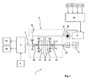
- FIG. 1 a device 1 for controlling an active vehicle steering system according to the invention.
- This device comprises a steering differential 2 which is interposed between a steering wheel 3 and a steering control means 4.
- the vehicle considered here is a steering wheel vehicle (tracked vehicle or non-steering wheeled vehicle).
- the steering control means 4 is therefore a hydrostatic steering control group.
- Such a steering control group uses the power of a heat engine 5 to manage the speed differential between a right crawler 6a and a left crawler 6b (or a right wheel train and a left wheel train for a non-steering wheeled vehicle).
- the shifting instruction is provided by the output shaft 7 of the driving differential 2.
- Group 4 is not the subject of the present invention and it is therefore unnecessary to describe it in detail here.
- the direction setpoint provided by the device 1 is used by the group 4 to control the direction by shifting.
- the differential 2 receives at a first input 8 a counter steering command provided by a turn correction engine 9.
- This motor 9 is controlled by a computer 10 which uses the signals supplied by sensors 11, 12, 13, 14.
- sensors may include a gyrometer 11 providing the instantaneous angular velocity of the vehicle, and accelerometers or strain gauges 12, 13, 14 for measuring the reaction forces exerted by the ground on the means of mobility (which will make it possible to estimate the adhesion).
- the steering wheel 3 is furthermore connected to a second input 15 of the differential 2 via a non-return means 16 making it possible to prevent the differential 2 from returning to the steering wheel 3.
- the figure 1 shows the internal architecture of the differential 2. It can be seen that the second input 15 is connected to a first satellite gate 16 while the output 7 is connected to a second satellite gate 17. The two satellite gates mesh with the ring gear 18 and the gear The reduction between the input 15 and the output 7 is therefore in principle 1: 1 when the two solar 19 and 20 are blocked.
- the first solar 19 is integral with the differential housing 2.
- the second solar 20 is rotated by the counter-rotating motor 9 via the first inlet 8 which is connected to a pinion 21 meshing with the second sun 20.
- the steering setpoint which is given by the differential 2 is therefore a setpoint which is corrected by the counter-steering motor 9 taking into account the measurements of adhesion and behavior of the vehicle which are made with the aid of the computer 10 (which received appropriate programming).
- a brake 22 is interposed between the counter-rotating motor 9 and the first inlet 8.
- This brake 22 is a brake for lack of current. It ensures the blocking of the first input 8 when the motor 9 is no longer powered (for example as a result of an incident electric). Such an arrangement makes it possible to avoid, in the event of a failure of the engine 9, that the control of the steering wheel 3 causes the pivoting of the shaft of the motor 9 rather than that of the output shaft 7.
- the steering wheel 3 is thus connected to the second input 15 of the differential 2 via the non-return means 16.
- Such a means makes it possible to prevent the forces 2 from returning to the steering wheel 3.
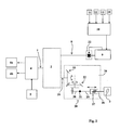
- the figure 2 shows an embodiment in which the non-return means 16 comprises a system associating a screw 26 integral with the flywheel 3 and a nut 27.
- the nut 27 drives a linear / rotary motion converter 28 of the connecting rod / crank type.
- This converter 28 comprises a set of links 29, 30 articulated at 31, and rotating a conical pinion 32.
- the conical pinion 32 meshes with an orthogonal pinion 33 which is integral with the second inlet 15.
Landscapes
- Engineering & Computer Science (AREA)
- Chemical & Material Sciences (AREA)
- Combustion & Propulsion (AREA)
- Transportation (AREA)
- Mechanical Engineering (AREA)
- Automation & Control Theory (AREA)
- Steering Control In Accordance With Driving Conditions (AREA)
- Power Steering Mechanism (AREA)
- Retarders (AREA)
- Pinball Game Machines (AREA)
- Servomotors (AREA)
- Non-Deflectable Wheels, Steering Of Trailers, Or Other Steering (AREA)
Abstract
Description
- Le domaine technique de l'invention est celui des dispositifs permettant la commande d'une direction active.
- Les directions actives sont des organes de conduite d'un véhicule qui permettent de corriger un ordre de braquage apporté par le conducteur lorsque cet ordre risque de compromettre la stabilité du véhicule.
- On connaît ainsi par le brevet
FR-2681449 - Cette correction est le plus souvent apportée au niveau d'un différentiel mécanique. En effet un tel équipement permet de combiner un ordre de consigne donné (par exemple par un volant) avec un ordre de correction donné par un moteur qui est piloté par le calculateur en fonction des mesures de roulis qui sont effectuées.
- Le brevet
US-7063636 décrit un tel dispositif de direction active dans lequel le volant agit sur une entrée d'un différentiel tandis qu'un moteur électrique de correction de braquage agit sur le porte satellite de ce différentiel. - Avec un tel dispositif le pilotage reste possible, même en cas de défaillance du moteur de correction. Il y a en effet une liaison directe via le différentiel entre le volant et la sortie commandant les roues.
- Cependant un tel dispositif est associé à une direction hydraulique assistée qui permet de compenser dans une certaine mesure les chocs ou retour d'efforts qui pourraient être communiqués au volant lors des mises en route du moteur de compensation.
- Un tel dispositif de direction assistée n'est pas toujours mis en oeuvre, notamment dans les véhicules à pilotage par ripage ou se dirigeant par ripage, tels que les véhicules chenillés ou à roues non directrices.
- En effet, dans ces véhicules la commande de direction est amplifiée à l'aide d'un moyen spécifique qui est le groupe hydrostatique de commande de direction (GHD). Ce moyen est disposé en aval du différentiel de pilotage et il ne peut amortir les chocs provoqués par le moteur de correction de braquage.
- Les brevets
W02005/100130 ,DE102005007307 etEP-1548411 décrivent tous des dispositifs de commande de direction par braquage. Ces dispositifs comprennent également des moyens de direction assistée qui assurent un filtrage des chocs reçus. - L'invention a pour but de proposer un dispositif de commande d'une direction active pour véhicules se dirigeant par ripage et qui permette d'assurer la commande directe de la direction à partir du volant, même en cas de défaillance du moteur de correction.
- Le dispositif selon l'invention permet ainsi d'éviter un retour de chocs vers le volant malgré l'absence de mécanisme de direction hydraulique assistée.
- L'invention trouve ainsi plus particulièrement application pour la commande en direction des véhicules chenillés ou à roues non directrices
- Ainsi, l'invention a pour objet un dispositif de commande d'une direction active d'un véhicule se dirigeant par ripage. La commande de direction d'un tel véhicule se fait non pas par braquage des roues mais en donnant un différentiel de vitesse des roues d'un côté du véhicule par rapport aux roues situées d'un autre côté du véhicule. Le dispositif comprend un différentiel de pilotage qui est interposé entre un volant et un moyen de commande de direction constitué par un groupe hydrostatique de commande de direction, différentiel qui reçoit par ailleurs au niveau d'une première entrée une commande de contre braquage fournie par un moteur de correction de virage, dispositif caractérisé en ce que le volant est relié à une deuxième entrée du différentiel par un moyen anti-retour permettant d'empêcher une remontée d'effort du différentiel vers le volant, le moyen anti-retour comprenant un système vis écrou couplé à un convertisseur de mouvement linéaire/rotatif tel qu'un système bielle manivelle.
- Selon une variante de l'invention, le dispositif pourra comprendre un moyen de freinage à manque de courant interposé entre la première entrée et le moteur de correction de virage.
- L'invention sera mieux comprise à la lecture de la description qui va suivre de différents modes de réalisation, description faite en référence aux dessins annexés et dans lesquels :
- la
figure 1 est un schéma cinématique général d'un dispositif selon l'invention, - la
figure 2 est un schéma simplifié d'un deuxième mode de réalisation de l'invention. - On a représenté sur la
figure 1 , un dispositif 1 de commande d'une direction active de véhicule selon l'invention. - Ce dispositif comprend un différentiel de pilotage 2 qui est interposé entre un volant 3 et un moyen de commande de direction 4.
- Le véhicule considéré est ici un véhicule à direction par ripage (véhicule chenillé ou bien véhicule à roues non directrices). Le moyen de commande de direction 4 est donc un groupe hydrostatique de commande de direction.
- Un tel groupe de commande de direction est bien connu. Il utilise la puissance d'un moteur thermique 5 pour gérer le différentiel de vitesse entre une chenille droite 6a et une chenille gauche 6b (ou un train de roues droit et un train de roues gauche pour un véhicule à roues non directrices). La consigne de ripage est fournie par l'arbre de sortie 7 du différentiel de pilotage 2.
- Le groupe 4 ne fait pas l'objet de la présente invention et il est donc inutile de le décrire ici en détails.
- La consigne de direction fournie par le dispositif 1 est donc utilisée par le groupe 4 pour commander la direction par ripage.
- Le différentiel 2 reçoit au niveau d'une première entrée 8 une commande de contre braquage fournie par un moteur 9 de correction de virage. Ce moteur 9 est commandé par un calculateur 10 qui utilise les signaux fournis par des capteurs 11, 12, 13, 14. Ces capteurs pourront comprendre un gyromètre 11 fournissant la vitesse angulaire instantanée du véhicule, et des accéléromètres ou des jauges de contraintes 12,13,14 permettant de mesurer les efforts de réaction exercés par le sol sur les moyens de mobilité (ce qui permettra d'estimer l'adhérence).
- Le traitement de ces différents signaux pour en déduire une consigne de contre braquage est décrit par le brevet
FR2681449 - Le volant 3 est par ailleurs relié à une deuxième entrée 15 du différentiel 2 par l'intermédiaire d'un moyen anti-retour 16 permettant d'empêcher une remontée d'efforts du différentiel 2 vers le volant 3.
- La
figure 1 montre l'architecture interne du différentiel 2. On voit que la deuxième entrée 15 est reliée à un premier porte satellites 16 tandis que la sortie 7 est reliée à un deuxième porte satellites 17. Les deux porte satellites engrènent sur la couronne 18 et le rapport de réduction entre l'entrée 15 et la sortie 7 est donc en principe de 1:1 lorsque les deux solaires 19 et 20 sont bloqués. - Le premier solaire 19 est solidaire du carter du différentiel 2.
- Le deuxième solaire 20 est entraîné en rotation par le moteur de contre braquage 9 par l'intermédiaire de la première entrée 8 qui est raccordée à un pignon 21 engrenant sur le deuxième solaire 20.
- La consigne de braquage qui est donnée par le différentiel 2 est donc une consigne qui est corrigée par le moteur de contre braquage 9 en tenant compte des mesures d'adhérence et de comportement du véhicule qui sont faites à l'aide du calculateur 10 (qui a reçu une programmation appropriée).
- On remarque sur la
figure 1 qu'un frein 22 est interposé entre le moteur de contre braquage 9 et la première entrée 8. - Ce frein 22 est un frein à manque de courant. Il assure le blocage de la première entrée 8 lorsque le moteur 9 n'est plus alimenté (par exemple comme suite à un incident électrique). Une telle disposition permet d'éviter, en cas de défaillance du moteur 9, que la commande du volant 3 ne provoque le pivotement de l'arbre du moteur 9 plutôt que celui de l'arbre de sortie 7.
- Il serait possible à titre de variante de remplacer le frein à manque de courant 22 par un moyen anti-retour tel une liaison vis-écrou.
- Conformément à l'invention le volant 3 est donc relié à la deuxième entrée 15 du différentiel 2 par l'intermédiaire du moyen anti-retour 16. Un tel moyen permet d'empêcher une remontée d'efforts du différentiel 2 vers le volant 3.
- Une telle remontée d'efforts intervient principalement lors des chocs occasionnés par la mise en action du moteur de contre braquage 9.
- Un mode de réalisation de ces moyens anti-retour va maintenant être décrit en référence à la
figure 2 . - La
figure 2 montre un mode de réalisation dans lequel le moyen anti-retour 16 comprend un système associant une vis 26 solidaire du volant 3 et un écrou 27. L'écrou 27 entraîne un convertisseur de mouvement linéaire/rotatif 28 du type bielle/manivelle. - Ce convertisseur 28 comprend un jeu de biellettes 29, 30, articulées en 31, et faisant pivoter un pignon conique 32. Le pignon conique 32 engrène sur un pignon orthogonal 33 qui est solidaire de la deuxième entrée 15.
- Une telle solution permet, sous une forme relativement compacte et présentant des frottements réduits, d'assurer l'anti-retour en évitant toute démultiplication.
- On aura ainsi aisément un rapport de 1:1 entre le pivotement du volant 3 et le pivotement de la deuxième entrée 15.
Claims (2)
- Dispositif (1) de commande d'une direction active d'un véhicule se dirigeant par ripage, dispositif comprenant un différentiel de pilotage (2) qui est interposé entre un volant (3) et un moyen (4) de commande de direction constitué par un groupe hydrostatique de commande de direction, différentiel qui reçoit par ailleurs au niveau d'une première entrée (8) une commande de contre braquage fournie par un moteur (9) de correction de virage, dispositif caractérisé en ce que le volant (3) est relié à une deuxième entrée (15) du différentiel (2) par un moyen anti-retour (16) permettant d'empêcher une remontée d'effort du différentiel (2) vers le volant (3), le moyen anti-retour (16) comprenant un système vis écrou (26, 27) couplé à un convertisseur (28) de mouvement linéaire/rotatif tel qu'un système bielle manivelle.
- Dispositif de commande d'une direction active selon la revendication 1, caractérisé en ce qu'il comprend un moyen de freinage (22) à manque de courant interposé entre la première entrée (8) et le moteur de correction de virage (9).
Applications Claiming Priority (2)
| Application Number | Priority Date | Filing Date | Title |
|---|---|---|---|
| FR0802879A FR2931436B1 (fr) | 2008-05-23 | 2008-05-23 | Dispositif de commande d'une direction active. |
| EP09290354A EP2123538B1 (fr) | 2008-05-23 | 2009-05-13 | Dispositif de commande d'une direction active |
Related Parent Applications (1)
| Application Number | Title | Priority Date | Filing Date |
|---|---|---|---|
| EP09290354.1 Division | 2009-05-13 |
Publications (2)
| Publication Number | Publication Date |
|---|---|
| EP2284064A1 true EP2284064A1 (fr) | 2011-02-16 |
| EP2284064B1 EP2284064B1 (fr) | 2012-04-04 |
Family
ID=40028932
Family Applications (2)
| Application Number | Title | Priority Date | Filing Date |
|---|---|---|---|
| EP09290354A Active EP2123538B1 (fr) | 2008-05-23 | 2009-05-13 | Dispositif de commande d'une direction active |
| EP10013753A Active EP2284064B1 (fr) | 2008-05-23 | 2009-05-13 | Dispositif de commande d'une direction active |
Family Applications Before (1)
| Application Number | Title | Priority Date | Filing Date |
|---|---|---|---|
| EP09290354A Active EP2123538B1 (fr) | 2008-05-23 | 2009-05-13 | Dispositif de commande d'une direction active |
Country Status (4)
| Country | Link |
|---|---|
| US (1) | US8177020B2 (fr) |
| EP (2) | EP2123538B1 (fr) |
| AT (2) | ATE552157T1 (fr) |
| FR (1) | FR2931436B1 (fr) |
Families Citing this family (1)
| Publication number | Priority date | Publication date | Assignee | Title |
|---|---|---|---|---|
| CN102072301B (zh) * | 2010-11-19 | 2013-03-13 | 东莞市明慧管理咨询有限公司 | 独立变速驱动系统 |
Citations (5)
| Publication number | Priority date | Publication date | Assignee | Title |
|---|---|---|---|---|
| FR2681449A1 (fr) | 1991-09-12 | 1993-03-19 | Giat Ind Sa | Procede et dispositif de commande du virage d'un vehicule chenille ou a roues non directrices. |
| EP1548411A2 (fr) | 2003-12-22 | 2005-06-29 | Denso Corporation | Appareil et procédé pour détecter une rotation angulaire |
| WO2005100130A1 (fr) | 2004-04-14 | 2005-10-27 | Daimlerchrysler Ag | Systeme de direction |
| US7063636B2 (en) | 2003-06-16 | 2006-06-20 | Delphi Technologies, Inc. | Mechanically linked active steering system |
| DE102005007307A1 (de) | 2005-02-16 | 2006-08-17 | Zf Lenksysteme Gmbh | Lenkung |
Family Cites Families (4)
| Publication number | Priority date | Publication date | Assignee | Title |
|---|---|---|---|---|
| US5703775A (en) * | 1993-09-16 | 1997-12-30 | Honda Giken Kogyo Kabushiki Kaisha | Vehicle steering control system |
| US6655494B2 (en) * | 2002-04-19 | 2003-12-02 | Delphi Technologies, Inc. | Active front steering actuator and method for controlling a vehicle |
| US7306535B2 (en) * | 2004-06-29 | 2007-12-11 | Delphi Technologies, Inc. | Vehicle steering device and method |
| DE102004031462B4 (de) * | 2004-06-30 | 2017-02-09 | Renk Ag | Einrichtung zur Umkehrung der Lenkbewegung einer Lenkradwelle eines Kettenfahrzeugs oder Radfahrzeugs mit Radseitenlenkung |
-
2008
- 2008-05-23 FR FR0802879A patent/FR2931436B1/fr active Active
-
2009
- 2009-05-13 EP EP09290354A patent/EP2123538B1/fr active Active
- 2009-05-13 AT AT10013753T patent/ATE552157T1/de active
- 2009-05-13 AT AT09290354T patent/ATE522426T1/de not_active IP Right Cessation
- 2009-05-13 EP EP10013753A patent/EP2284064B1/fr active Active
- 2009-05-26 US US12/453,883 patent/US8177020B2/en active Active
Patent Citations (5)
| Publication number | Priority date | Publication date | Assignee | Title |
|---|---|---|---|---|
| FR2681449A1 (fr) | 1991-09-12 | 1993-03-19 | Giat Ind Sa | Procede et dispositif de commande du virage d'un vehicule chenille ou a roues non directrices. |
| US7063636B2 (en) | 2003-06-16 | 2006-06-20 | Delphi Technologies, Inc. | Mechanically linked active steering system |
| EP1548411A2 (fr) | 2003-12-22 | 2005-06-29 | Denso Corporation | Appareil et procédé pour détecter une rotation angulaire |
| WO2005100130A1 (fr) | 2004-04-14 | 2005-10-27 | Daimlerchrysler Ag | Systeme de direction |
| DE102005007307A1 (de) | 2005-02-16 | 2006-08-17 | Zf Lenksysteme Gmbh | Lenkung |
Also Published As
| Publication number | Publication date |
|---|---|
| ATE522426T1 (de) | 2011-09-15 |
| EP2123538B1 (fr) | 2011-08-31 |
| EP2284064B1 (fr) | 2012-04-04 |
| FR2931436B1 (fr) | 2010-10-08 |
| US20090288892A1 (en) | 2009-11-26 |
| ATE552157T1 (de) | 2012-04-15 |
| FR2931436A1 (fr) | 2009-11-27 |
| EP2123538A1 (fr) | 2009-11-25 |
| US8177020B2 (en) | 2012-05-15 |
Similar Documents
| Publication | Publication Date | Title |
|---|---|---|
| US7530422B2 (en) | Force and position control for active front steering | |
| EP3829909B1 (fr) | Systeme de propulsion pour vehicule electrique | |
| FR3022515A1 (fr) | Assistance de direction mixte comprenant une boucle d'asservissement en couple pilotee en consigne par un controleur de position destine a l'asservissement en trajectoire | |
| JP4811595B2 (ja) | 車両用操舵装置 | |
| US7322898B2 (en) | Active front steering actuator | |
| KR102057594B1 (ko) | 전동식 파워스티어링 장치가 장착된 트랙터 앞차축 | |
| FR2848519A1 (fr) | Direction assistee avec assistance hydraulique | |
| US7063636B2 (en) | Mechanically linked active steering system | |
| FR3041922A1 (fr) | Systeme de modification du rapport de direction pour vehicule a bras telescopique et vehicule correspondant | |
| CN113811480B (zh) | 车辆转向设备 | |
| KR102174602B1 (ko) | 자동차의 조향장치 | |
| US7374015B2 (en) | Motor-driven power steering system | |
| FR3036350A1 (fr) | Ensemble servofrein | |
| EP2284064B1 (fr) | Dispositif de commande d'une direction active | |
| CA3040559C (fr) | Atterrisseur d'aeronef a partie inferieure orientable et dispositif d'orientation simplifie | |
| US20090032324A1 (en) | Vehicle with dual steering mechanisms | |
| WO2018050568A1 (fr) | Systeme de direction electrohydraulique assistee pilotee electroniquement pour vehicules utilitaires, pompe et boitier de direction pour un tel systeme | |
| CN105848954B (zh) | 一种用于道路车辆的主传动装置 | |
| WO2021144525A1 (fr) | Procédé conçu pour asservir une position d'une crémaillère d'un véhicule à une consigne de position en fonction de contraintes cinématiques imposées sur un mouvement du véhicule | |
| FR2914260A1 (fr) | Vehicule motorise comprenant une unite de controle du vehicule se trouvant en situation de virage et procede correspondant. | |
| FR2896471A3 (fr) | Vehicule comprenant une commande de direction sans liaison mecanique | |
| KR100613774B1 (ko) | 조향비 가변 기능을 갖는 차량의 조향장치 | |
| JP2012126223A (ja) | 駆動力分配装置 | |
| FR3151567A1 (fr) | Architecture de direction assistée sans liaison mécanique entre le volant de direction et le mécanisme de direction du véhicule | |
| FR3069302A1 (fr) | Procede de pilotage ameliore pour assistance hydraulique |
Legal Events
| Date | Code | Title | Description |
|---|---|---|---|
| PUAI | Public reference made under article 153(3) epc to a published international application that has entered the european phase |
Free format text: ORIGINAL CODE: 0009012 |
|
| AC | Divisional application: reference to earlier application |
Ref document number: 2123538 Country of ref document: EP Kind code of ref document: P |
|
| AK | Designated contracting states |
Kind code of ref document: A1 Designated state(s): AT BE BG CH CY CZ DE DK EE ES FI FR GB GR HR HU IE IS IT LI LT LU LV MC MK MT NL NO PL PT RO SE SI SK TR |
|
| REG | Reference to a national code |
Ref country code: DE Ref legal event code: R079 Ref document number: 602009006290 Country of ref document: DE Free format text: PREVIOUS MAIN CLASS: B62D0005000000 Ipc: B62D0011000000 |
|
| 17P | Request for examination filed |
Effective date: 20110816 |
|
| RIC1 | Information provided on ipc code assigned before grant |
Ipc: B62D 11/00 20060101AFI20110831BHEP Ipc: B62D 7/22 20060101ALI20110831BHEP Ipc: B62D 5/00 20060101ALI20110831BHEP |
|
| GRAP | Despatch of communication of intention to grant a patent |
Free format text: ORIGINAL CODE: EPIDOSNIGR1 |
|
| GRAS | Grant fee paid |
Free format text: ORIGINAL CODE: EPIDOSNIGR3 |
|
| GRAA | (expected) grant |
Free format text: ORIGINAL CODE: 0009210 |
|
| AC | Divisional application: reference to earlier application |
Ref document number: 2123538 Country of ref document: EP Kind code of ref document: P |
|
| AK | Designated contracting states |
Kind code of ref document: B1 Designated state(s): AT BE BG CH CY CZ DE DK EE ES FI FR GB GR HR HU IE IS IT LI LT LU LV MC MK MT NL NO PL PT RO SE SI SK TR |
|
| REG | Reference to a national code |
Ref country code: GB Ref legal event code: FG4D Free format text: NOT ENGLISH |
|
| REG | Reference to a national code |
Ref country code: CH Ref legal event code: EP |
|
| REG | Reference to a national code |
Ref country code: AT Ref legal event code: REF Ref document number: 552157 Country of ref document: AT Kind code of ref document: T Effective date: 20120415 |
|
| REG | Reference to a national code |
Ref country code: IE Ref legal event code: FG4D Free format text: LANGUAGE OF EP DOCUMENT: FRENCH |
|
| REG | Reference to a national code |
Ref country code: DE Ref legal event code: R096 Ref document number: 602009006290 Country of ref document: DE Effective date: 20120531 |
|
| REG | Reference to a national code |
Ref country code: NL Ref legal event code: VDEP Effective date: 20120404 |
|
| REG | Reference to a national code |
Ref country code: SE Ref legal event code: TRGR |
|
| REG | Reference to a national code |
Ref country code: AT Ref legal event code: MK05 Ref document number: 552157 Country of ref document: AT Kind code of ref document: T Effective date: 20120404 |
|
| LTIE | Lt: invalidation of european patent or patent extension |
Effective date: 20120404 |
|
| PG25 | Lapsed in a contracting state [announced via postgrant information from national office to epo] |
Ref country code: CY Free format text: LAPSE BECAUSE OF FAILURE TO SUBMIT A TRANSLATION OF THE DESCRIPTION OR TO PAY THE FEE WITHIN THE PRESCRIBED TIME-LIMIT Effective date: 20120404 Ref country code: FI Free format text: LAPSE BECAUSE OF FAILURE TO SUBMIT A TRANSLATION OF THE DESCRIPTION OR TO PAY THE FEE WITHIN THE PRESCRIBED TIME-LIMIT Effective date: 20120404 Ref country code: LT Free format text: LAPSE BECAUSE OF FAILURE TO SUBMIT A TRANSLATION OF THE DESCRIPTION OR TO PAY THE FEE WITHIN THE PRESCRIBED TIME-LIMIT Effective date: 20120404 Ref country code: NO Free format text: LAPSE BECAUSE OF FAILURE TO SUBMIT A TRANSLATION OF THE DESCRIPTION OR TO PAY THE FEE WITHIN THE PRESCRIBED TIME-LIMIT Effective date: 20120704 Ref country code: IS Free format text: LAPSE BECAUSE OF FAILURE TO SUBMIT A TRANSLATION OF THE DESCRIPTION OR TO PAY THE FEE WITHIN THE PRESCRIBED TIME-LIMIT Effective date: 20120804 Ref country code: PL Free format text: LAPSE BECAUSE OF FAILURE TO SUBMIT A TRANSLATION OF THE DESCRIPTION OR TO PAY THE FEE WITHIN THE PRESCRIBED TIME-LIMIT Effective date: 20120404 Ref country code: SI Free format text: LAPSE BECAUSE OF FAILURE TO SUBMIT A TRANSLATION OF THE DESCRIPTION OR TO PAY THE FEE WITHIN THE PRESCRIBED TIME-LIMIT Effective date: 20120404 |
|
| BERE | Be: lapsed |
Owner name: NEXTER SYSTEMS Effective date: 20120531 |
|
| PG25 | Lapsed in a contracting state [announced via postgrant information from national office to epo] |
Ref country code: PT Free format text: LAPSE BECAUSE OF FAILURE TO SUBMIT A TRANSLATION OF THE DESCRIPTION OR TO PAY THE FEE WITHIN THE PRESCRIBED TIME-LIMIT Effective date: 20120806 Ref country code: GR Free format text: LAPSE BECAUSE OF FAILURE TO SUBMIT A TRANSLATION OF THE DESCRIPTION OR TO PAY THE FEE WITHIN THE PRESCRIBED TIME-LIMIT Effective date: 20120705 Ref country code: HR Free format text: LAPSE BECAUSE OF FAILURE TO SUBMIT A TRANSLATION OF THE DESCRIPTION OR TO PAY THE FEE WITHIN THE PRESCRIBED TIME-LIMIT Effective date: 20120404 Ref country code: LV Free format text: LAPSE BECAUSE OF FAILURE TO SUBMIT A TRANSLATION OF THE DESCRIPTION OR TO PAY THE FEE WITHIN THE PRESCRIBED TIME-LIMIT Effective date: 20120404 |
|
| PG25 | Lapsed in a contracting state [announced via postgrant information from national office to epo] |
Ref country code: MC Free format text: LAPSE BECAUSE OF NON-PAYMENT OF DUE FEES Effective date: 20120531 |
|
| PG25 | Lapsed in a contracting state [announced via postgrant information from national office to epo] |
Ref country code: EE Free format text: LAPSE BECAUSE OF FAILURE TO SUBMIT A TRANSLATION OF THE DESCRIPTION OR TO PAY THE FEE WITHIN THE PRESCRIBED TIME-LIMIT Effective date: 20120404 Ref country code: RO Free format text: LAPSE BECAUSE OF FAILURE TO SUBMIT A TRANSLATION OF THE DESCRIPTION OR TO PAY THE FEE WITHIN THE PRESCRIBED TIME-LIMIT Effective date: 20120404 Ref country code: NL Free format text: LAPSE BECAUSE OF FAILURE TO SUBMIT A TRANSLATION OF THE DESCRIPTION OR TO PAY THE FEE WITHIN THE PRESCRIBED TIME-LIMIT Effective date: 20120404 Ref country code: AT Free format text: LAPSE BECAUSE OF FAILURE TO SUBMIT A TRANSLATION OF THE DESCRIPTION OR TO PAY THE FEE WITHIN THE PRESCRIBED TIME-LIMIT Effective date: 20120404 Ref country code: CZ Free format text: LAPSE BECAUSE OF FAILURE TO SUBMIT A TRANSLATION OF THE DESCRIPTION OR TO PAY THE FEE WITHIN THE PRESCRIBED TIME-LIMIT Effective date: 20120404 Ref country code: DK Free format text: LAPSE BECAUSE OF FAILURE TO SUBMIT A TRANSLATION OF THE DESCRIPTION OR TO PAY THE FEE WITHIN THE PRESCRIBED TIME-LIMIT Effective date: 20120404 Ref country code: SK Free format text: LAPSE BECAUSE OF FAILURE TO SUBMIT A TRANSLATION OF THE DESCRIPTION OR TO PAY THE FEE WITHIN THE PRESCRIBED TIME-LIMIT Effective date: 20120404 |
|
| PLBE | No opposition filed within time limit |
Free format text: ORIGINAL CODE: 0009261 |
|
| STAA | Information on the status of an ep patent application or granted ep patent |
Free format text: STATUS: NO OPPOSITION FILED WITHIN TIME LIMIT |
|
| REG | Reference to a national code |
Ref country code: IE Ref legal event code: MM4A |
|
| PG25 | Lapsed in a contracting state [announced via postgrant information from national office to epo] |
Ref country code: IT Free format text: LAPSE BECAUSE OF FAILURE TO SUBMIT A TRANSLATION OF THE DESCRIPTION OR TO PAY THE FEE WITHIN THE PRESCRIBED TIME-LIMIT Effective date: 20120404 Ref country code: MK Free format text: LAPSE BECAUSE OF FAILURE TO SUBMIT A TRANSLATION OF THE DESCRIPTION OR TO PAY THE FEE WITHIN THE PRESCRIBED TIME-LIMIT Effective date: 20120404 Ref country code: BE Free format text: LAPSE BECAUSE OF NON-PAYMENT OF DUE FEES Effective date: 20120531 |
|
| 26N | No opposition filed |
Effective date: 20130107 |
|
| PG25 | Lapsed in a contracting state [announced via postgrant information from national office to epo] |
Ref country code: ES Free format text: LAPSE BECAUSE OF FAILURE TO SUBMIT A TRANSLATION OF THE DESCRIPTION OR TO PAY THE FEE WITHIN THE PRESCRIBED TIME-LIMIT Effective date: 20120715 Ref country code: IE Free format text: LAPSE BECAUSE OF NON-PAYMENT OF DUE FEES Effective date: 20120513 |
|
| REG | Reference to a national code |
Ref country code: DE Ref legal event code: R097 Ref document number: 602009006290 Country of ref document: DE Effective date: 20130107 |
|
| PG25 | Lapsed in a contracting state [announced via postgrant information from national office to epo] |
Ref country code: MT Free format text: LAPSE BECAUSE OF FAILURE TO SUBMIT A TRANSLATION OF THE DESCRIPTION OR TO PAY THE FEE WITHIN THE PRESCRIBED TIME-LIMIT Effective date: 20120404 Ref country code: BG Free format text: LAPSE BECAUSE OF FAILURE TO SUBMIT A TRANSLATION OF THE DESCRIPTION OR TO PAY THE FEE WITHIN THE PRESCRIBED TIME-LIMIT Effective date: 20120704 |
|
| REG | Reference to a national code |
Ref country code: CH Ref legal event code: PL |
|
| PG25 | Lapsed in a contracting state [announced via postgrant information from national office to epo] |
Ref country code: CH Free format text: LAPSE BECAUSE OF NON-PAYMENT OF DUE FEES Effective date: 20130531 Ref country code: LI Free format text: LAPSE BECAUSE OF NON-PAYMENT OF DUE FEES Effective date: 20130531 |
|
| PG25 | Lapsed in a contracting state [announced via postgrant information from national office to epo] |
Ref country code: TR Free format text: LAPSE BECAUSE OF FAILURE TO SUBMIT A TRANSLATION OF THE DESCRIPTION OR TO PAY THE FEE WITHIN THE PRESCRIBED TIME-LIMIT Effective date: 20120404 |
|
| PG25 | Lapsed in a contracting state [announced via postgrant information from national office to epo] |
Ref country code: LU Free format text: LAPSE BECAUSE OF NON-PAYMENT OF DUE FEES Effective date: 20120513 |
|
| PG25 | Lapsed in a contracting state [announced via postgrant information from national office to epo] |
Ref country code: HU Free format text: LAPSE BECAUSE OF FAILURE TO SUBMIT A TRANSLATION OF THE DESCRIPTION OR TO PAY THE FEE WITHIN THE PRESCRIBED TIME-LIMIT Effective date: 20090513 |
|
| REG | Reference to a national code |
Ref country code: FR Ref legal event code: PLFP Year of fee payment: 8 |
|
| REG | Reference to a national code |
Ref country code: FR Ref legal event code: PLFP Year of fee payment: 9 |
|
| REG | Reference to a national code |
Ref country code: FR Ref legal event code: PLFP Year of fee payment: 10 |
|
| PGFP | Annual fee paid to national office [announced via postgrant information from national office to epo] |
Ref country code: DE Payment date: 20250423 Year of fee payment: 17 |
|
| PGFP | Annual fee paid to national office [announced via postgrant information from national office to epo] |
Ref country code: GB Payment date: 20250423 Year of fee payment: 17 |
|
| PGFP | Annual fee paid to national office [announced via postgrant information from national office to epo] |
Ref country code: FR Payment date: 20250423 Year of fee payment: 17 |
|
| PGFP | Annual fee paid to national office [announced via postgrant information from national office to epo] |
Ref country code: SE Payment date: 20250423 Year of fee payment: 17 |