EP2283971A1 - Scale removing method and scale removing device - Google Patents
Scale removing method and scale removing device Download PDFInfo
- Publication number
- EP2283971A1 EP2283971A1 EP09725423A EP09725423A EP2283971A1 EP 2283971 A1 EP2283971 A1 EP 2283971A1 EP 09725423 A EP09725423 A EP 09725423A EP 09725423 A EP09725423 A EP 09725423A EP 2283971 A1 EP2283971 A1 EP 2283971A1
- Authority
- EP
- European Patent Office
- Prior art keywords
- steel pipe
- pipe
- pressure jet
- blasting
- nozzle
- Prior art date
- Legal status (The legal status is an assumption and is not a legal conclusion. Google has not performed a legal analysis and makes no representation as to the accuracy of the status listed.)
- Withdrawn
Links
Images


Classifications
-
- B—PERFORMING OPERATIONS; TRANSPORTING
- B24—GRINDING; POLISHING
- B24C—ABRASIVE OR RELATED BLASTING WITH PARTICULATE MATERIAL
- B24C1/00—Methods for use of abrasive blasting for producing particular effects; Use of auxiliary equipment in connection with such methods
- B24C1/08—Methods for use of abrasive blasting for producing particular effects; Use of auxiliary equipment in connection with such methods for polishing surfaces, e.g. smoothing a surface by making use of liquid-borne abrasives
- B24C1/086—Descaling; Removing coating films
-
- B—PERFORMING OPERATIONS; TRANSPORTING
- B24—GRINDING; POLISHING
- B24C—ABRASIVE OR RELATED BLASTING WITH PARTICULATE MATERIAL
- B24C3/00—Abrasive blasting machines or devices; Plants
- B24C3/32—Abrasive blasting machines or devices; Plants designed for abrasive blasting of particular work, e.g. the internal surfaces of cylinder blocks
- B24C3/325—Abrasive blasting machines or devices; Plants designed for abrasive blasting of particular work, e.g. the internal surfaces of cylinder blocks for internal surfaces, e.g. of tubes
-
- B—PERFORMING OPERATIONS; TRANSPORTING
- B24—GRINDING; POLISHING
- B24C—ABRASIVE OR RELATED BLASTING WITH PARTICULATE MATERIAL
- B24C9/00—Appurtenances of abrasive blasting machines or devices, e.g. working chambers, arrangements for handling used abrasive material
- B24C9/003—Removing abrasive powder out of the blasting machine
Definitions
- the present invention relates to a scale removing method and scale removing apparatus wherein the internal surface of a steel pipe is subjected to blasting process where abrasive particles are ejected through a high-pressure jet nozzle and hit the internal surface of the steel pipe.
- Steel pipes are often subjected to heat treatment depending on the usage purpose thereof.
- a blasting has been known as the method for removing scale from the internal surface of steel pipe.
- scale formed on the inner surfaces of steel pipe is removed by impacts of an abrasive particle such as iron, stainless steel, alumina, or quartz sand.
- the blasting involves, for example, sand blasting, shot blasting, and grit blasting.
- a high-pressure jet system, a negative-pressure suction system, or a combination of these two systems is adopted as the abrasive particle ejecting method.
- a steel pipe is placed on turnable rollers, and while the steel pipe is rotated, a high-pressure jet nozzle is inserted from an end part of the steel pipe and is moved in the longitudinal direction with an abrasive particle blown onto the internal surface of steel pipe through the high-pressure jet nozzle, whereby scale is removed by impacts of the abrasive particle to the internal surface of steel pipe.
- Dust particles after blasting are usually collected by a dust collector provided in an end part on the opposite side to the end part of steel pipe from which the high-pressure jet nozzle is inserted.
- a suction machine is installed at one end of a steel pipe, and while the interior of steel pipe is maintained at a negative pressure by the suction machine, abrasive particles are charged from the other end in the state, whereby scale is removed by the impacts of the abrasive particle, moving in the steel pipe, to the internal surface of the steel pipe.
- the blasting apparatus of high-pressure jet type has a disadvantage that a large equipment space is required because a pipe for transporting the abrasive particles to the nozzle (transportation pipe) has a long length.
- the blasting apparatus of negative-pressure suction type has a disadvantage that the scale removing capability is low because the impact angle of abrasive particles is low.
- Patent Document 1 In order to compensate for these disadvantages of the blasting apparatuses, in Patent Document 1, the present applicant disclosed an invention relating to scale removing equipment wherein: a first high-pressure jet blasting section for subjecting the internal surface of one pipe end part of a steel pipe to blasting; a second high-pressure jet blasting section for subjecting the internal surface of the other pipe end part of the steel pipe to blasting; and a negative-pressure suction blasting section for subjecting the internal surface of the overall length of steel pipe to blasting are arranged in juxtaposition, and steel pipe transfer devices are provided between these blasting sections.
- scale formed near the end part of steel pipe which is less liable to be removed by the negative-pressure suction blasting, is removed by the high-pressure jet blasting.
- blower used for the dust collector for high-pressure jet blasting a blower having a low capacity (usually, about 40 kW or lower) is used as compared with the blower used for the suction machine for negative-pressure suction blasting (90 kW or higher). The reason for this is as described below.
- the suction machine for negative-pressure suction blasting must create a negative pressure in the steel pipe to produce an air flow sufficient to transport the abrasive particles, whereas in the high-pressure jet blasting, the abrasive particles are transported by the high-pressure jet nozzle, so that the purpose of the dust collector therefor is merely to collect dust particles (abrasive particles and chips thereof, removed scales, etc.).
- Figure 4 shows a problem with a conventional high-pressure jet blasting method.
- compressed air is sent from a compressor (not shown), and abrasive particles are supplied from an abrasive particles tank (not shown) to an abrasive particles transfer pipe 1, whereby high-pressure abrasive particles (not shown) is ejected through a nozzle 2.
- a blower having a capacity corresponding to the flow rate at the nozzle 2 can be used.
- the above-described gap is in a fixed range, the amount of air flowing into the steel pipe 3 increases beyond expectation, exceeding the suction capability of the dust collector 4, and dust particles 5 may scatter into the atmosphere.
- the present invention has been made to solve the above problems, and accordingly an object thereof is to provide a scale removing method and scale removing apparatus wherein the ejector effect is reduced, and dust particles do not scatter into the atmosphere even with a low-capacity dust collector in high-pressure jet blasting.
- the present invention has been made to solve the above problems, and the gist thereof is a scale removing method shown in item (1) and a scale removing apparatus shown in item (2).
- any mode of items (a) to (c) described below is preferably adopted.
- dust particles do not scatter into the atmosphere even with a low-capacity dust collector in high-pressure jet blasting, so that energy can be saved, and at the same time, the work environment can be improved.
- a scale removing apparatus 7 in accordance with the present invention is a scale removing apparatus that performs blasting on the internal surface of a steel pipe 3 by causing abrasive particles (not shown) ejected through a high-pressure jet nozzle 2 to collide with the internal surface of the steel pipe 3.
- the scale removing apparatus 7 has the high-pressure jet nozzle 2 for ejecting the abrasive particles, a dust collector 4 for collecting dust particles after blasting, and restraining means 6 for restraining air from flowing into the steel pipe 3 from an end part thereof due to the flow of abrasive particles ejected through the high-pressure jet nozzle 2.
- FIG. 1 An example of a scale removing apparatus 7 in accordance with the present invention is shown in Figure 1 .
- the dust collector 4 is installed so that dust particles can be collected from a pipe end (the right end part of the steel pipe 3 in Figure 1 ) on the opposite side to a nozzle insertion end (the left end part of the steel pipe 3 in Figure 1 ) of the high-pressure jet nozzle 2 of the steel pipe 3, and the restraining means 6 is formed of a plate material having a size capable of covering the nozzle insertion end (the left end part of the steel pipe 3 in Figure 1 ) of the high-pressure jet nozzle 2 of the steel pipe 3 and has a through hole where the high-pressure jet nozzle 2 can be slid.
- FIG. 2 The other example of a scale removing apparatus 7 in accordance with the present invention is shown in Figure 2 .
- the apparatus is the same as that shown in Figure 1 in that a dust collector 4 is installed so that dust particles can be collected from a pipe end (the right end part of a steel pipe 3 in Figure 2 ) on the opposite side to a nozzle insertion end (the left end part of the steel pipe 3 in Figure 2 ) of a high-pressure jet nozzle 2 of the steel pipe 3.
- restraining means 6 is attached to the outer periphery of the high-pressure jet nozzle 2, and is formed of a disc-shaped plate material having an outside diameter equivalent to the inside diameter of the steel pipe 3 so as to be capable of sliding in the steel pipe 3.
- restraining means 6 is installed at a pipe end (the right end part of a steel pipe 3 in Figure 3 ) on the opposite side to a nozzle insertion end (the left end part of the steel pipe 3 in Figure 3 ) of a high-pressure jet nozzle 2 of the steel pipe 3, a dust collector (not shown) is installed so that dust particles can be collected from the same pipe end as the nozzle insertion end (the left end part of the steel pipe 3 in Figure 3 ) of the high-pressure jet nozzle 2 of the steel pipe 3, and the restraining means 6 is formed of a plate material having a size capable of covering the end part of the steel pipe 3.
- An expandable material such as rubber is desirably used as the restraining means.
- the restraining means is not subject to any special restriction if it is configured so as to be capable of restraining air from flowing into the steel pipe from the end part of the steel pipe.
- the size of the restraining means must be changed. Therefore, in the case where the size of steel pipe subjected to blasting changes frequently, it is desirable to use a plate material having a size far larger than the outside diameter of steel pipe as in the examples shown in Figures 1 and 3 .
- the scale removing apparatus of the present invention is especially effective in removing scale at the pipe end of steel pipe by using the high-pressure jet nozzle.
- the in-pipe air flow rate is 2 Nm 3 /min or lower, all dust particles produced at the time of blasting can be removed even with a low-capacity blower of 14.0 kW (diameter: 100 mm, 1750 rpm, -5000 mmAq).
- the in-pipe air flow rate exceeds 5 Nm 3 /min, the above-described low-capacity blower is insufficient to collect dust, and dust particles are liable to scatter into the atmosphere. Therefore, the in-pipe air flow rate must be controlled so as to be 5 Nm 3 /min or lower, preferably 2 Nm 3 /min or lower.
- the in-pipe air flow rate increases.
- the in-pipe air flow rate can be kept at 5 Nm 3 /min or lower.
- the in-pipe air flow rate exceeds 5 Nm 3 /min.
- the in-pipe air flow rate increases.
- the in-pipe air flow rate can be kept at 5 Nm 3 /min or lower.
- the in-pipe air flow rate exceeds 5 Nm 3 /min.
- the in-pipe air flow rate did not increase so much, and in any examples, the in-pipe air flow rate could be kept at 5 Nm 3 /min or lower.
- the experiment was conducted by providing a restraining plate, serving as the restraining means, having a size larger than the inside diameter of steel pipe at a position near the pipe end on the nozzle insertion side and by variously changing a distance "a" between the pipe end and the restraining plate.
- the in-pipe flow rate is an average value of flow rates at one point at the circle central portion at the pipe end on the dust collector connection side and at four points in the circumferential portion, that is, at five points indicated by black dots in Figure 8 .
- Figure 9 shows the relationship between the ratio of distance "a" to nozzle diameter (hereinafter, referred to as a "position index X”) and the ratio of in-pipe flow rate to jet flow rate (hereinafter, referred to as a "flow rate index Y").
- position index X the ratio of distance "a" to nozzle diameter
- flow rate index Y the ratio of in-pipe flow rate to jet flow rate
- dust particles do not scatter into the atmosphere even with a low-capacity dust collector in high-pressure jet blasting, so that energy can be saved and the work environment can be improved.
Landscapes
- Engineering & Computer Science (AREA)
- Mechanical Engineering (AREA)
- Cleaning In General (AREA)
Abstract
Description
- The present invention relates to a scale removing method and scale removing apparatus wherein the internal surface of a steel pipe is subjected to blasting process where abrasive particles are ejected through a high-pressure jet nozzle and hit the internal surface of the steel pipe.
- Steel pipes are often subjected to heat treatment depending on the usage purpose thereof. For improving the quality of steel pipe, it is important to remove scale (descaling) formed on the inner and outer surfaces of steel pipe at the time of heat treatment. A blasting has been known as the method for removing scale from the internal surface of steel pipe. In the blasting, scale formed on the inner surfaces of steel pipe is removed by impacts of an abrasive particle such as iron, stainless steel, alumina, or quartz sand. The blasting involves, for example, sand blasting, shot blasting, and grit blasting. A high-pressure jet system, a negative-pressure suction system, or a combination of these two systems is adopted as the abrasive particle ejecting method.
- In the blasting apparatus of high-pressure jet system, for example, a steel pipe is placed on turnable rollers, and while the steel pipe is rotated, a high-pressure jet nozzle is inserted from an end part of the steel pipe and is moved in the longitudinal direction with an abrasive particle blown onto the internal surface of steel pipe through the high-pressure jet nozzle, whereby scale is removed by impacts of the abrasive particle to the internal surface of steel pipe. Dust particles after blasting are usually collected by a dust collector provided in an end part on the opposite side to the end part of steel pipe from which the high-pressure jet nozzle is inserted.
- In the blasting apparatus of negative-pressure suction system, for example, a suction machine is installed at one end of a steel pipe, and while the interior of steel pipe is maintained at a negative pressure by the suction machine, abrasive particles are charged from the other end in the state, whereby scale is removed by the impacts of the abrasive particle, moving in the steel pipe, to the internal surface of the steel pipe.
- The blasting apparatus of high-pressure jet type has a disadvantage that a large equipment space is required because a pipe for transporting the abrasive particles to the nozzle (transportation pipe) has a long length. The blasting apparatus of negative-pressure suction type has a disadvantage that the scale removing capability is low because the impact angle of abrasive particles is low.
- In order to compensate for these disadvantages of the blasting apparatuses, in
Patent Document 1, the present applicant disclosed an invention relating to scale removing equipment wherein: a first high-pressure jet blasting section for subjecting the internal surface of one pipe end part of a steel pipe to blasting; a second high-pressure jet blasting section for subjecting the internal surface of the other pipe end part of the steel pipe to blasting; and a negative-pressure suction blasting section for subjecting the internal surface of the overall length of steel pipe to blasting are arranged in juxtaposition, and steel pipe transfer devices are provided between these blasting sections. In this invention, scale formed near the end part of steel pipe, which is less liable to be removed by the negative-pressure suction blasting, is removed by the high-pressure jet blasting. -
- Patent Document 1:
JP11-320413A - As a blower used for the dust collector for high-pressure jet blasting, a blower having a low capacity (usually, about 40 kW or lower) is used as compared with the blower used for the suction machine for negative-pressure suction blasting (90 kW or higher). The reason for this is as described below. The suction machine for negative-pressure suction blasting must create a negative pressure in the steel pipe to produce an air flow sufficient to transport the abrasive particles, whereas in the high-pressure jet blasting, the abrasive particles are transported by the high-pressure jet nozzle, so that the purpose of the dust collector therefor is merely to collect dust particles (abrasive particles and chips thereof, removed scales, etc.).
-
Figure 4 shows a problem with a conventional high-pressure jet blasting method. As shown inFigure 4 , in the high-pressure jet blasting, for example, compressed air is sent from a compressor (not shown), and abrasive particles are supplied from an abrasive particles tank (not shown) to an abrasiveparticles transfer pipe 1, whereby high-pressure abrasive particles (not shown) is ejected through anozzle 2. In the case where the gap between the outside diameter of the abrasive particles transferpipe 1 and the inside diameter of asteel pipe 3, a blasted material, is small or sufficiently large, , a blower having a capacity corresponding to the flow rate at thenozzle 2 can be used. However, in the case where the above-described gap is in a fixed range, the amount of air flowing into thesteel pipe 3 increases beyond expectation, exceeding the suction capability of thedust collector 4, anddust particles 5 may scatter into the atmosphere. - The reason for this is that during the blasting, the flow of abrasive particles and air are produced in the
steel pipe 3 by the abrasive particles ejected through the high-pressure jet nozzle 2, and due to the ejector effect thereof, air of about several times the flow rate of the high-pressure jet nozzle 2 flows into thesteel pipe 3 from a portion near an end part of steel pipe (the left end part in the figure). - It can be thought that the capacity of the dust collector is increased to solve the above-described problem,. However, since the ejector effect is increased or decreased depending on the inside diameter of the steel pipe, it is not preferable from the viewpoint of energy saving that the suction capability of dust collector be designed so as to match the case where the ejector effect is great.
- The present invention has been made to solve the above problems, and accordingly an object thereof is to provide a scale removing method and scale removing apparatus wherein the ejector effect is reduced, and dust particles do not scatter into the atmosphere even with a low-capacity dust collector in high-pressure jet blasting.
- The present invention has been made to solve the above problems, and the gist thereof is a scale removing method shown in item (1) and a scale removing apparatus shown in item (2).
-
- (1) A method for removing a scale formed on an internal surface of a steel pipe by subjecting the internal surface of the steel pipe to a blasting process wherein abrasive particles are ejected through a high-pressure jet nozzle and collide with the internal surface of the steel pipe, wherein the blasting process is performed while air is restrained from flowing into the steel pipe from an end part of the steel pipe due to the flow (motion) of the abrasive particle.
-
- (2) An apparatus for removing a scale formed on an internal surface of a steel pipe by subjecting the internal surface of the steel pipe to a blasting process wherein abrasive particles are ejected through a high-pressure jet nozzle and collide with the internal surface of the steel pipe, wherein the apparatus has: the high-pressure jet nozzle for ejecting the abrasive particles;
a dust collector for collecting dust particles after blasting; and restraining means for restraining air from flowing into the steel pipe from an end part of the steel pipe due to the flow of the abrasive particles. - As the scale removing apparatus shown in the above item (2), for example, any mode of items (a) to (c) described below is preferably adopted.
-
- (a) The dust collector is installed so as to be capable of collecting dust particles from a pipe end on the opposite side to a nozzle insertion end of the steel pipe, and the restraining means is formed of a plate material having a size capable of covering the nozzle insertion end of the steel pipe and has a through hole where the high-pressure jet nozzle can be slid.
-
- (b) The dust collector is installed so as to be capable of collecting dust particles from a pipe end on the opposite side to a nozzle insertion end of the steel pipe, and the restraining means is attached to the outer periphery of the high-pressure jet nozzle and is formed of a disc-shaped plate material having an outside diameter equivalent to an inside diameter of the steel pipe so as to be capable of sliding in the steel pipe.
-
- (c) The restraining means, which is formed of a plate material having a size capable of covering the end part of the steel pipe, is installed at a pipe end on the opposite side to a nozzle insertion end of the steel pipe, and the dust collector is installed so that dust particles can be collected from the same pipe end as the nozzle insertion end of the steel pipe.
- According to the present invention, dust particles do not scatter into the atmosphere even with a low-capacity dust collector in high-pressure jet blasting, so that energy can be saved, and at the same time, the work environment can be improved.
-
-
Figure 1 is a perspective view showing one example of a scale removing apparatus in accordance with the present invention; -
Figure 2 is a perspective view showing another example of a scale removing apparatus in accordance with the present invention; -
Figure 3 is a perspective view showing still another example of a scale removing apparatus in accordance with the present invention; -
Figure 4 is a perspective view of a conventional scale removing apparatus; -
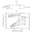
Figure 5 is a graph showing the relationship between pipe inside diameter and in-pipe air flow rate in an experiment conducted while changing the pipe inside diameter and a nozzle pressure variously; -
Figure 6 is a graph showing the relationship between pipe inside diameter and in-pipe air flow rate in example embodiment of the present invention and comparative example; -
Figure 7 is a perspective view showing experimental conditions; -
Figure 8 is a sectional view showing measurement positions of in-pipe flow rate; and -
Figure 9 is a graph showing the relationship between position index X and flow rate index Y. - An embodiment of the present invention will now be described with reference to
Figures 1 to 3 . As shown inFigure 1 , ascale removing apparatus 7 in accordance with the present invention is a scale removing apparatus that performs blasting on the internal surface of asteel pipe 3 by causing abrasive particles (not shown) ejected through a high-pressure jet nozzle 2 to collide with the internal surface of thesteel pipe 3. Thescale removing apparatus 7 has the high-pressure jet nozzle 2 for ejecting the abrasive particles, adust collector 4 for collecting dust particles after blasting, and restraining means 6 for restraining air from flowing into thesteel pipe 3 from an end part thereof due to the flow of abrasive particles ejected through the high-pressure jet nozzle 2. - Thereby, during blasting, air can be restrained from flowing into the
steel pipe 3 from the end part (the left end part in the figure) of thesteel pipe 3. Therefore, dust particles produced by blasting can be collected even if the capacity of the dust collector is not increased. - An example of a
scale removing apparatus 7 in accordance with the present invention is shown inFigure 1 . In the apparatus, for example, thedust collector 4 is installed so that dust particles can be collected from a pipe end (the right end part of thesteel pipe 3 inFigure 1 ) on the opposite side to a nozzle insertion end (the left end part of thesteel pipe 3 inFigure 1 ) of the high-pressure jet nozzle 2 of thesteel pipe 3, and the restraining means 6 is formed of a plate material having a size capable of covering the nozzle insertion end (the left end part of thesteel pipe 3 inFigure 1 ) of the high-pressure jet nozzle 2 of thesteel pipe 3 and has a through hole where the high-pressure jet nozzle 2 can be slid. - The other example of a
scale removing apparatus 7 in accordance with the present invention is shown inFigure 2 . The apparatus is the same as that shown inFigure 1 in that adust collector 4 is installed so that dust particles can be collected from a pipe end (the right end part of asteel pipe 3 inFigure 2 ) on the opposite side to a nozzle insertion end (the left end part of thesteel pipe 3 inFigure 2 ) of a high-pressure jet nozzle 2 of thesteel pipe 3. In the apparatus, however, restraining means 6 is attached to the outer periphery of the high-pressure jet nozzle 2, and is formed of a disc-shaped plate material having an outside diameter equivalent to the inside diameter of thesteel pipe 3 so as to be capable of sliding in thesteel pipe 3. - The other example of a
scale removing apparatus 7 in accordance with the present invention is shown inFigure 3 . In the apparatus, for example, restraining means 6 is installed at a pipe end (the right end part of asteel pipe 3 inFigure 3 ) on the opposite side to a nozzle insertion end (the left end part of thesteel pipe 3 inFigure 3 ) of a high-pressure jet nozzle 2 of thesteel pipe 3, a dust collector (not shown) is installed so that dust particles can be collected from the same pipe end as the nozzle insertion end (the left end part of thesteel pipe 3 inFigure 3 ) of the high-pressure jet nozzle 2 of thesteel pipe 3, and the restraining means 6 is formed of a plate material having a size capable of covering the end part of thesteel pipe 3. - An expandable material such as rubber is desirably used as the restraining means. The restraining means is not subject to any special restriction if it is configured so as to be capable of restraining air from flowing into the steel pipe from the end part of the steel pipe. For example, in the example shown in
Figure 2 , in the case where the size of the steel pipe differs greatly, the size of the restraining means must be changed. Therefore, in the case where the size of steel pipe subjected to blasting changes frequently, it is desirable to use a plate material having a size far larger than the outside diameter of steel pipe as in the examples shown inFigures 1 and 3 . Also, in the examples shown inFigures 1 and 2 , two dust collectors must be provided at the pipe end on the opposite side to the nozzle insertion end to collect dust particles. However, in the example shown inFigure 3 , only one dust collector may be provided to collect dust particles from the same pipe end as the nozzle insertion end. Therefore, the example shown inFigure 3 is desirable, because the configuration of apparatus is simple and the number of consumable parts can be reduced and a repair cost can be decrease. - In the case where scale is removed throughout the overall length of steel pipe by using the high-pressure jet nozzle, the length of the transportation pipe must inevitably be increased, and also the amount of abrasive particles to be ejected must be increased. Therefore, the abrasive particles remain easily in the pipe. If the remaining amount of abrasive particles increases, the work for moving the transportation pipe is sometimes difficult to do. For this reason, the scale removing apparatus of the present invention is especially effective in removing scale at the pipe end of steel pipe by using the high-pressure jet nozzle.
- In order to verify the effects of the present invention, an experiment was conducted where pipes having different inside diameter is prepared the high-pressure jet nozzle was first inserted from one end of each pipe, and then air was ejected while the nozzle jet pressure (nozzle pressure) was changed variously, whereby the flow rate of air at the pipe end on the opposite side to the nozzle insertion side was examined. In this experiment, the inside diameter of the abrasive particles transfer pipe was set at 5.27 mm, and the amount of air discharged from the pipe end part when air is blown into the steel pipes having different inside diameters by using the high-pressure jet nozzle (nozzle pressure: 4.9 to 39.2 N/cm2) was measured. The measurement results are shown in
Figure 5 . - If the in-pipe air flow rate is 2 Nm3/min or lower, all dust particles produced at the time of blasting can be removed even with a low-capacity blower of 14.0 kW (diameter: 100 mm, 1750 rpm, -5000 mmAq). However, if the in-pipe air flow rate exceeds 5 Nm3/min, the above-described low-capacity blower is insufficient to collect dust, and dust particles are liable to scatter into the atmosphere. Therefore, the in-pipe air flow rate must be controlled so as to be 5 Nm3/min or lower, preferably 2 Nm3/min or lower.
- As shown in
Figure 5 , with an increase in the nozzle pressure, the in-pipe air flow rate increases. For example, as is apparent from the example where the pipe inside diameter is 55 mm, in the examples where the nozzle pressure is 4.9 N/cm2 and 9.8 N/cm2, the in-pipe air flow rate can be kept at 5 Nm3/min or lower. However, in the example where the nozzle pressure is 19.6 N/cm2 or higher, the in-pipe air flow rate exceeds 5 Nm3/min. On the other hand, in the case where the pipe inside diameter is large, the in-pipe air flow rate increases. For example, as is apparent from the example where the nozzle pressure is 29.4 N/cm2, in the examples where the pipe inside diameter is 31 mm and 44 mm, the in-pipe air flow rate can be kept at 5 Nm3/min or lower. However, in the example where the pipe inside diameter is 55 mm or larger, the in-pipe air flow rate exceeds 5 Nm3/min. - Next, an experiment was conducted where pipes having different inside diameter is prepared, the restraining means of the present invention shown in
Figure 1 was used, the high-pressure jet nozzle was inserted into one end of each pipe, and air having a nozzle pressure of 39.2 N/cm2 was ejected in the state where the pipe end on the nozzle insertion side was closed, whereby the flow rate of air at the pipe end on the opposite side to the nozzle insertion side was examined as in theembodiment 1. The experimental results are shown inFigure 6 . A comparative example inFigure 6 is the example where the nozzle pressure is 39.2 N/cm2 in theembodiment 1. - As shown in
Figure 6 , in the example embodiment of the present invention, even when air having a pressure as high as 39.2 N/cm2 was ejected, the in-pipe air flow rate did not increase so much, and in any examples, the in-pipe air flow rate could be kept at 5 Nm3/min or lower. - Successively, the same experiment as the above-described one was conducted by using the restraining means shown in
Figures 2 and 3 . In this experiment, the in-pipe air flow rate could be kept at 5 Nm3/min or lower as in the example embodiment of the present invention shown inFigure 6 . - Next, to study the conditions where dust particles are not produced, steel pipes each having an outside diameter of 88.9 mm, 114.3 mm, and 177.8 mm were prepared, the high-pressure jet nozzle (nozzle diameter: 10.0 mm) was inserted into the steel pipe from one end of steel pipe, and the abrasive particles were blown (jet flow rate: 5.9 Nm3/min) and was sucked by the dust collector connected to the other end of steel pipe (suction flow rate: 11.9 Nm3/min), whereby the production state of dust particles and the in-pipe flow rate at this time were examined. The ratio of suction flow rate to jet flow rate (hereinafter, referred to as "Yc") was 2. As shown in
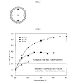
Figure 7 , the experiment was conducted by providing a restraining plate, serving as the restraining means, having a size larger than the inside diameter of steel pipe at a position near the pipe end on the nozzle insertion side and by variously changing a distance "a" between the pipe end and the restraining plate. The in-pipe flow rate is an average value of flow rates at one point at the circle central portion at the pipe end on the dust collector connection side and at four points in the circumferential portion, that is, at five points indicated by black dots inFigure 8 . -
Figure 9 shows the relationship between the ratio of distance "a" to nozzle diameter (hereinafter, referred to as a "position index X") and the ratio of in-pipe flow rate to jet flow rate (hereinafter, referred to as a "flow rate index Y"). As shown inFigure 9 , for any of the steel pipes, with an increase in the value of position index X, the value of flow rate index Y increases. This tendency becomes remarkable with an increase in steel pipe size. On the other hand, for any of the steel pipes, if the flow rate index Y exceeded 2, that is, exceeded Yc, dust particles were produced. Therefore, in order to prevent dust particles, it is important that the flow rate index Y do not exceed Yc. In order for the in-pipe flow rate not to exceed the suction flow rate of dust collector, the distance X must be set in a proper range in relation to the nozzle diameter. - According to the present invention, dust particles do not scatter into the atmosphere even with a low-capacity dust collector in high-pressure jet blasting, so that energy can be saved and the work environment can be improved.
-
- 1. abrasive particles transfer pipe
- 2. high-pressure jet nozzle
- 3. steel pipe
- 4. dust collector
- 5. dust particles
- 6. restraining means
- 7. scale removing apparatus
Claims (5)
- A method for removing a scale formed on an internal surface of a steel pipe by subjecting the internal surface of the steel pipe to a blasting process wherein abrasive particles are ejected through a high-pressure jet nozzle and collide with the internal surface of the steel pipe,
wherein the blasting process is performed while air is restrained from flowing into the steel pipe from an end part of the steel pipe due to the flow of the abrasive particles. - An apparatus for removing a scale formed on an internal surface of a steel pipe by subjecting the internal surface of the steel pipe to a blasting process wherein abrasive particles are ejected through a high-pressure jet nozzle and collide with the internal surface of the steel pipe,
wherein the apparatus has:the high-pressure jet nozzle for ejecting the abrasive particles;a dust collector for collecting dust particles after blasting; andrestraining means for restraining air from flowing into the steel pipe from an end part of the steel pipe due to the flow of the abrasive particles. - The apparatus for removing scale according to claim 2,
wherein the dust collector is installed so as to be capable of collecting dust particles from a pipe end on the opposite side to a nozzle insertion end of the steel pipe, and
the restraining means is formed of a plate material having a size capable of covering the nozzle insertion end of the steel pipe and has a through hole where the high-pressure jet nozzle can be slid. - The scale removing apparatus according to claim 2,
wherein the dust collector is installed so as to be capable of collecting dust particles from a pipe end on the opposite side to a nozzle insertion end of the steel pipe, and
the restraining means is attached to the outer periphery of the high-pressure jet nozzle and is formed of a disc-shaped plate material having an outside diameter equivalent to an inside diameter of the steel pipe so as to be capable of sliding in the steel pipe. - The scale removing apparatus according to claim 2,
wherein the restraining means, which is formed of a plate material having a size capable of covering the end part of the steel pipe, is installed at a pipe end on the opposite side to a nozzle insertion end of the steel pipe, and
the dust collector is installed so that dust particles can be collected from the same pipe end as the nozzle insertion end of the steel pipe.
Applications Claiming Priority (2)
| Application Number | Priority Date | Filing Date | Title |
|---|---|---|---|
| JP2008079439 | 2008-03-26 | ||
| PCT/JP2009/055744 WO2009119540A1 (en) | 2008-03-26 | 2009-03-24 | Scale removing method and scale removing device |
Publications (2)
| Publication Number | Publication Date |
|---|---|
| EP2283971A1 true EP2283971A1 (en) | 2011-02-16 |
| EP2283971A4 EP2283971A4 (en) | 2014-03-19 |
Family
ID=41113732
Family Applications (1)
| Application Number | Title | Priority Date | Filing Date |
|---|---|---|---|
| EP09725423.9A Withdrawn EP2283971A4 (en) | 2008-03-26 | 2009-03-24 | DESCALING METHOD AND DESCALING DEVICE |
Country Status (6)
| Country | Link |
|---|---|
| US (1) | US20110065363A1 (en) |
| EP (1) | EP2283971A4 (en) |
| JP (1) | JP4400761B2 (en) |
| CN (1) | CN101980834A (en) |
| BR (1) | BRPI0910400A8 (en) |
| WO (1) | WO2009119540A1 (en) |
Families Citing this family (6)
| Publication number | Priority date | Publication date | Assignee | Title |
|---|---|---|---|---|
| WO2010122851A1 (en) * | 2009-04-21 | 2010-10-28 | シャープ株式会社 | Blasting apparatus and method for blasting |
| US9085064B2 (en) * | 2010-09-09 | 2015-07-21 | Envirologics Engineering Inc. | System for dispensing abrasives into a gas stream for cleaning pipe interiors |
| CN102806328A (en) * | 2011-06-02 | 2012-12-05 | 江苏永钢集团有限公司 | Purging device for ferric oxide on billet surface |
| DE102014102147B4 (en) * | 2014-02-19 | 2017-03-09 | Wheelabrator Group Gmbh | A method of solidifying blasting a pipe inner wall of a curved workpiece with a workpiece bore and jet nozzle unit and working chamber system therefor |
| US10435779B2 (en) * | 2017-03-14 | 2019-10-08 | Ford Motor Company | Precision air flow routing devices and method for thermal spray coating applications |
| CN112223124B (en) * | 2020-11-19 | 2025-03-28 | 浙江金洲管道工业有限公司 | A self-sealing internal circulation shot blasting and rust removal device for the inner wall of a large-diameter steel pipe |
Family Cites Families (9)
| Publication number | Priority date | Publication date | Assignee | Title |
|---|---|---|---|---|
| US3835587A (en) * | 1973-07-03 | 1974-09-17 | W Hall | Pipe cleaning apparatus and method |
| FR2572965B1 (en) * | 1984-11-09 | 1988-06-10 | Framatome Sa | METHOD AND APPARATUS FOR HAMMER COMPRESSION OF A STEAM GENERATOR TUBE SET IN A TUBULAR PLATE |
| US5160548A (en) * | 1991-09-09 | 1992-11-03 | Ohmstede Mechanical Services, Inc. | Method for cleaning tube bundles using a slurry |
| JPH05228841A (en) * | 1992-02-13 | 1993-09-07 | Mitsubishi Materials Corp | Pipe inner surface blasting device |
| JPH06270065A (en) * | 1993-03-23 | 1994-09-27 | Kawasaki Steel Corp | Blasting method for steel pipe inner surface |
| US5664992A (en) * | 1994-06-20 | 1997-09-09 | Abclean America, Inc. | Apparatus and method for cleaning tubular members |
| JP3533942B2 (en) | 1998-05-08 | 2004-06-07 | 住友金属工業株式会社 | Scale removal method and equipment |
| JP4052424B2 (en) * | 2001-07-03 | 2008-02-27 | 三菱重工業株式会社 | Foreign matter removing apparatus and method |
| US6988935B2 (en) * | 2001-08-08 | 2006-01-24 | Mitsubishi Heavy Industries, Ltd. | Foreign matter removing device and method |
-
2009
- 2009-03-24 WO PCT/JP2009/055744 patent/WO2009119540A1/en not_active Ceased
- 2009-03-24 JP JP2009513490A patent/JP4400761B2/en not_active Expired - Fee Related
- 2009-03-24 CN CN2009801107910A patent/CN101980834A/en active Pending
- 2009-03-24 EP EP09725423.9A patent/EP2283971A4/en not_active Withdrawn
- 2009-03-24 BR BRPI0910400A patent/BRPI0910400A8/en not_active Application Discontinuation
-
2010
- 2010-09-21 US US12/887,092 patent/US20110065363A1/en not_active Abandoned
Also Published As
| Publication number | Publication date |
|---|---|
| US20110065363A1 (en) | 2011-03-17 |
| JPWO2009119540A1 (en) | 2011-07-21 |
| CN101980834A (en) | 2011-02-23 |
| BRPI0910400A2 (en) | 2015-09-29 |
| WO2009119540A1 (en) | 2009-10-01 |
| JP4400761B2 (en) | 2010-01-20 |
| EP2283971A4 (en) | 2014-03-19 |
| BRPI0910400A8 (en) | 2019-01-29 |
Similar Documents
| Publication | Publication Date | Title |
|---|---|---|
| CN101511540B (en) | Steel pipe inner surface sand blasting device, steel pipe inner surface sand blasting method, and method for manufacturing steel pipe with excellent inner surface surface properties | |
| US20110065363A1 (en) | Scale Removing Method and Scale Removing Apparatus | |
| EP2391481A1 (en) | Blast nozzle with blast media fragmenter | |
| CN104552023B (en) | A kind of elongated steel pipeline inwall numerical control shot-peening automated system | |
| US2739424A (en) | Method of sandblasting | |
| CN113211330A (en) | Graded continuous spraying machine table combination device | |
| JP2019104106A (en) | Surface treatment method of r-t-b system sintered magnet and manufacturing method | |
| CN103238005B (en) | Hollow spring and manufacturing method thereof | |
| CN206200771U (en) | Weighing sensor strain regions abrasive blast equipment based on double sand-blasting gun lateral spray types | |
| CN211193529U (en) | Sand blasting equipment for inner wall of steel pipe | |
| JP5929323B2 (en) | Negative pressure suction blasting method and apparatus for pipe inner surface | |
| JP6949314B2 (en) | Steel structure maintenance method and steel structure maintenance treatment system | |
| JP6419737B2 (en) | Sand blasting device set and method for adjusting base of steel tower | |
| JPH09103960A (en) | Negative-pressure suction blasting device and method | |
| KR101127181B1 (en) | Impeller blast device | |
| CN204471212U (en) | The sand blasting apparatus of stainless steel tube three-layer polypropylene anti-corrosion pipe | |
| CN118372180B (en) | A shot blasting machine for stainless steel workpieces | |
| KR101195948B1 (en) | An air flow augmentation device for uv lamp cooling | |
| CN114473877B (en) | Sand blasting descaling polishing device | |
| CN224050980U (en) | Cleaning and drying device for grinding workpiece | |
| KR101852946B1 (en) | Shot treatment apparatus | |
| JP7036617B2 (en) | Scale removal method | |
| JP3533942B2 (en) | Scale removal method and equipment | |
| CN211332798U (en) | Shot blasting machine discharge apparatus | |
| CN208557190U (en) | Shot blasting machine |
Legal Events
| Date | Code | Title | Description |
|---|---|---|---|
| PUAI | Public reference made under article 153(3) epc to a published international application that has entered the european phase |
Free format text: ORIGINAL CODE: 0009012 |
|
| 17P | Request for examination filed |
Effective date: 20101026 |
|
| AK | Designated contracting states |
Kind code of ref document: A1 Designated state(s): AT BE BG CH CY CZ DE DK EE ES FI FR GB GR HR HU IE IS IT LI LT LU LV MC MK MT NL NO PL PT RO SE SI SK TR |
|
| AX | Request for extension of the european patent |
Extension state: AL BA RS |
|
| DAX | Request for extension of the european patent (deleted) | ||
| RAP1 | Party data changed (applicant data changed or rights of an application transferred) |
Owner name: NIPPON STEEL & SUMITOMO METAL CORPORATION |
|
| A4 | Supplementary search report drawn up and despatched |
Effective date: 20140213 |
|
| RIC1 | Information provided on ipc code assigned before grant |
Ipc: B24C 3/32 20060101AFI20140207BHEP Ipc: B24C 3/16 20060101ALI20140207BHEP Ipc: B24C 9/00 20060101ALI20140207BHEP |
|
| STAA | Information on the status of an ep patent application or granted ep patent |
Free format text: STATUS: THE APPLICATION IS DEEMED TO BE WITHDRAWN |
|
| 18D | Application deemed to be withdrawn |
Effective date: 20140916 |