EP2283923A2 - Linear cuvette array without positioning means - Google Patents
Linear cuvette array without positioning means Download PDFInfo
- Publication number
- EP2283923A2 EP2283923A2 EP10180535A EP10180535A EP2283923A2 EP 2283923 A2 EP2283923 A2 EP 2283923A2 EP 10180535 A EP10180535 A EP 10180535A EP 10180535 A EP10180535 A EP 10180535A EP 2283923 A2 EP2283923 A2 EP 2283923A2
- Authority
- EP
- European Patent Office
- Prior art keywords
- cuvette
- cuvettes
- array
- dimensional
- holder
- Prior art date
- Legal status (The legal status is an assumption and is not a legal conclusion. Google has not performed a legal analysis and makes no representation as to the accuracy of the status listed.)
- Withdrawn
Links
Images





Classifications
-
- B—PERFORMING OPERATIONS; TRANSPORTING
- B01—PHYSICAL OR CHEMICAL PROCESSES OR APPARATUS IN GENERAL
- B01L—CHEMICAL OR PHYSICAL LABORATORY APPARATUS FOR GENERAL USE
- B01L3/00—Containers or dishes for laboratory use, e.g. laboratory glassware; Droppers
- B01L3/50—Containers for the purpose of retaining a material to be analysed, e.g. test tubes
- B01L3/502—Containers for the purpose of retaining a material to be analysed, e.g. test tubes with fluid transport, e.g. in multi-compartment structures
- B01L3/5025—Containers for the purpose of retaining a material to be analysed, e.g. test tubes with fluid transport, e.g. in multi-compartment structures for parallel transport of multiple samples
- B01L3/50255—Multi-well filtration
-
- B—PERFORMING OPERATIONS; TRANSPORTING
- B01—PHYSICAL OR CHEMICAL PROCESSES OR APPARATUS IN GENERAL
- B01L—CHEMICAL OR PHYSICAL LABORATORY APPARATUS FOR GENERAL USE
- B01L3/00—Containers or dishes for laboratory use, e.g. laboratory glassware; Droppers
- B01L3/50—Containers for the purpose of retaining a material to be analysed, e.g. test tubes
- B01L3/508—Rigid containers without fluid transport within
- B01L3/5085—Rigid containers without fluid transport within for multiple samples, e.g. microtitration plates
- B01L3/50855—Rigid containers without fluid transport within for multiple samples, e.g. microtitration plates using modular assemblies of strips or of individual wells
-
- B—PERFORMING OPERATIONS; TRANSPORTING
- B01—PHYSICAL OR CHEMICAL PROCESSES OR APPARATUS IN GENERAL
- B01L—CHEMICAL OR PHYSICAL LABORATORY APPARATUS FOR GENERAL USE
- B01L2200/00—Solutions for specific problems relating to chemical or physical laboratory apparatus
- B01L2200/02—Adapting objects or devices to another
- B01L2200/025—Align devices or objects to ensure defined positions relative to each other
-
- B—PERFORMING OPERATIONS; TRANSPORTING
- B01—PHYSICAL OR CHEMICAL PROCESSES OR APPARATUS IN GENERAL
- B01L—CHEMICAL OR PHYSICAL LABORATORY APPARATUS FOR GENERAL USE
- B01L2200/00—Solutions for specific problems relating to chemical or physical laboratory apparatus
- B01L2200/02—Adapting objects or devices to another
- B01L2200/028—Modular arrangements
-
- B—PERFORMING OPERATIONS; TRANSPORTING
- B01—PHYSICAL OR CHEMICAL PROCESSES OR APPARATUS IN GENERAL
- B01L—CHEMICAL OR PHYSICAL LABORATORY APPARATUS FOR GENERAL USE
- B01L2300/00—Additional constructional details
- B01L2300/08—Geometry, shape and general structure
- B01L2300/0809—Geometry, shape and general structure rectangular shaped
- B01L2300/0829—Multi-well plates; Microtitration plates
Definitions
- the invention concerns an integrally built, linear array of cuvettes made of a plastic material, every cuvette of the array having the same shape and dimensions, and neighboring cuvettes being connected to each other by a single web. Furthermore, the invention provides also a two-dimensional array of cuvettes and a system comprising two or more two-dimensional arrays of cuvettes.
- EP1232792 describes a cuvette array 1] comprising cuvettes 12 with an open lower end 13, means for removably connecting 14 and means for positioning the cuvettes 15 in the cuvette holder as shown in Figure 1A .
- This invention is based on the observation that these positioning means are of disadvantage when welding a layer at the lower open end of the cuvettes.
- a steel matrix is imposed on the cuvettes.
- the steel matrix comprises wholes whose position and dimensions correspond with the position and dimension of the cuvettes in the array so that the steel plate may fit on the cuvettes.
- a layer is laid on the open lower ends of the cuvettes and welded, whereby the lower ends form the welding contour.
- a knife in dimension and form equivalent to the steel matrix punches the layer so that only the layer welded to cuvettes remains. The steel matrix stops the knife of cutting through the cuvette array.
- FIG. 1B shows a partial cross-section through a cuvette holder 16 with a cuvette array 11 of Figure 1A .
- the positioning means 15 prevent an accurate placement of a steel matrix 17 (see Figure 1B ).
- the steel matrix concisely locks up with the lower ends of the cuvettes 12 which form the welding contour 19.
- the distance of the lower end 18 of the inlayed steel matrix 17 and the welding contour 19 is to low for accurate welding and/or punching of the layer.
- a cuvette array 21 without positioning means allows to accurately position a steel matrix 17 below welding contour 29 (lower ends of cuvettes 22) so that a proper welding and cutting is possible.
- the present invention provides an integrally built, linear array of cuvettes made of a plastic material, every cuvette of the array having the same shape and dimensions, and neighboring cuvettes being connected to each other by a single web, each cuvette of said array has a symmetry axis (Y-Y), the symmetry axis (Y-Y) of every cuvette forming part of said array 21 of cuvettes lies in a plane (A-A) which extends along the length of said cuvette array, said array of cuvettes being characterized in that
- the main advantages of the invention are that it allows to perform the welding process steps accurately and efficiently.
- Every cuvette of array 21 has the same shape and dimensions and neighboring cuvettes are connected to each other by a single web 25, 26.
- Each of these single webs 25, 26 is flexible and has a curved shape.
- the symmetry axis Y-Y of every cuvette 22 which forms part of array 21 of cuvettes lies substantially in one and the same plane A-A which is a symmetry plane of cuvette array 21.
- the upper part of an intermediate cuvette 22 of array 21 is connected by a first single web 25 to a neighboring cuvette 23 which lies on one side of intermediate cuvette 22 and is connected by a second single web 26 to a neighboring cuvette 24 which lies on the opposite side of intermediate cuvette 22.
- the single webs 25, 26 are flexible and therefore facilitate the insertion of the cuvettes in a cuvette holder, e.g. cuvette holder 42 described hereinafter, in spite of variations of the length of cuvette array 21 which are due to different shrinkage coefficients of the different materials used for manufacture of cuvette arrays 21 by injection molding.
- These single webs 25, 26 may lie on either of two opposite sides of the plane A-A. This means that two successive single webs may lie on the same side of the plane A-A, or on the opposite side of the plane A-A. However, it is preferred that at least to single webs lie on opposite sides of the plane A-A.
- At least two of the cuvettes of the array 21 have means for removably connecting the cuvettes to cuvette holder 42 described hereinafter. These means are an integral part of the cuvette. Preferably, these connecting means are latches 31 and 32.
- the distribution of cuvettes with connecting means over the array is equitable. If two cuvettes have connecting means preferably the first and the last cuvettes has each connecting means, or second and the last but one cuvette has each connecting means, or the third and the last but two cuvette has each connecting means, and so on.
- the first cuvette, the third cuvette, the fourth, the fifth, the sixth and the eighth cuvette has each connecting means.
- Figure 3 shows a cross-section of one of the cuvettes, e.g. cuvette 22 of cuvette array 21.
- the cuvette has an upper chamber 27 and a lower chamber 28 which have a common symmetry axis Y-Y which passes through the centers of both chambers.
- Upper chamber 27 and lower chamber 28 have each a substantially cylindrical shape. The cross-section of upper chamber 27 at the central part thereof is larger than the cross-section of lower chamber 28.
- Lower chamber 28 has an open lower end 33.
- Upper chamber 27 has an open top end 34 and an annular bottom wall 35. This bottom wall has a central circular opening 36 which connects said upper chamber 27 with lower chamber 28.
- the inner surface 37 of bottom wall 35 is part of a conical surface the cross-section of which forms an angle of about 80 degrees with the symmetry axis Y-Y of the cuvette, so that there is an abrupt change of cross-section between said upper chamber 27 and said lower chamber 28.
- the cuvette array 21 is made by injection molding of a selected first plastic material which is particularly suitable for being used in combination with a second selected material of which a foil shaped layer is made. This layer is adapted to be closely attached to at least one cuvette of the array of cuvettes for covering at least one opening of the cuvette.
- the same plastic material may be used for said first plastic material and said second plastic material.
- the attachment of the foil shaped layer to one or more cuvettes can be effected e.g. by gluing the layer and the one or more cuvettes or by a welding process. Preferred is the attachment of the foil shaped layer by a welding process.
- the foil attached to one individual cuvette is attached only to this individual cuvette and has no connection with any other cuvette or with a foil attached to a different cuvette.
- the attachment of the layer to the cuvette must ensure a medium tight connection (liquid and/or gas tight connection) of these components.
- foil shaped layer Possible uses of such a foil shaped layer include e.g. its use as a filter and/or as a transparent closure (e.g. transparent to ultraviolet irradiation), which must not necessarily have the function of a filter.
- a transparent closure e.g. transparent to ultraviolet irradiation
- the filtration process can be effected by use of vacuum or pressure applied to the medium contained in each cuvette of a cuvette array.
- Suitable materials for a foil shaped layer usable as a filter and having a thickness in a range of 10 to 200 micrometer are for instance: polyvinylidenfluorid (PVDF), polycarbonat (PC), polysulfon (PSU), regenerated cellulose, polytetrafluorethylen (PTFE), PET, cyclic olefin copolymers (COC) and filter paper.
- PVDF polyvinylidenfluorid
- PC polycarbonat
- PSU polysulfon
- PTFE polytetrafluorethylen
- PET cyclic olefin copolymers
- COC cyclic olefin copolymers
- FIG. 5 such a foil shaped layer is adapted to be closely attached to the lower end of the cuvette.
- Figure 5 shows a cuvette 22 and a foil shaped layer 71 which is closely attached to cuvette 22 for covering the opening of this cuvette at the lower end 33 thereof.
- the injection molding apparatus for manufacturing the cuvette array is preferably so configured and dimensioned that injection molding of different materials having different shrinkage coefficients can be carried out with one and the same apparatus.
- the material of which this layer is made is so selected that properties of the layer are suitable for use with the material of which the cuvettes are made.
- the materials of the cuvette array and of the foil shaped layer are so selected that they are particularly well adapted for and thereby enable optimization of a particular process carried out with the assembly of cuvette array and foil shaped layer.
- Such processes are e.g. filtration, diffusion, concentration determination and "microspotting".
- cuvettes made of a hydrophilic material are suitably combined with ultrafiltration membranes for carrying out ultrafiltrations in an optimal way.
- Diffusion processes through artificial membranes are preferably carried out with hydrophobic filtration membranes, which are suitable for being combined by a melting process with cuvette material having similar hydrophobic properties.
- Filtration processes require hydrophilic or lipophilic properties of the cuvettes and of the filtration membrane attached thereto, and the selection of the materials of these components depends from the properties of the substance to be filtered.
- fragments are deposited by microspotting on the foil which is attached to the lower end of the cuvettes of cuvette array 21.
- cuvette array 21 celluloseacetate, polycarbonate, polyvinylidene fluoride (PVDF), polysulfones, polystyrene, polypropylene (PP) or cyclic olefin copolymers (COC). Materials with similar shrinkage coefficient (in connection with injection molding) and melting properties may also be used for manufacturing cuvette array 21.
- PVDF polyvinylidene fluoride
- PP polypropylene
- COC cyclic olefin copolymers
- Figure 6 shows a top view of a cuvette holder 42 which can be used to hold a plurality of the above described cuvette arrays 21 to form a two-dimensional cuvette array 41.
- Figure 7 shows a cross-section through a plane B-B of cuvette holder 42 in Figure 6 .
- cuvette holder 42 is of substantially rectangular shape and has four centering ribs located each on the outer surface of one of the corners of cuvette holder 42.
- Figure 8 shows a top view of a two-dimensional cuvette array 41 according to the invention.
- Figure 9 shows a cross-section through a plane C-C of two-dimensional cuvette array 41 in Figure 8 .
- a two-dimensional array 41 of cuvettes comprises a cuvette holder 42 having a matrix array 43 of openings 44 for receiving cuvettes 22 of at least one linear cuvette array 21 having the above described features.
- Each of the cuvettes 22 of cuvette array 21 has a shape and dimensions that snugly fits, also with connecting means, into one of openings 44 of cuvette holder 42.
- Cuvette holder 42 is so configured and dimensioned that two-dimensional array 41 is adapted to be used in a centrifuge. As shown by Figure 9 , cuvette holder 42 snugly fits into a holder plate 49 of a centrifuge.
- Figure 10 shows a cuvette holder 42 with a cuvette array 21 and a steel matrix 17 which is imposed on the cuvettes 22 of the cuvette array 21.
- the steel matrix 17 is imposed on the cuvettes as shown in Figure 10 .
- the steel matrix 17 comprises wholes whose position and dimensions correspond with the position and dimension of the cuvettes 22 in the array so that the steel plate 17 may fit on the cuvettes 22.
- a layer is laid on the open lower ends of the cuvettes and welded, whereby the lower ends form the welding contour 29.
- a knife in dimension and form equivalent to the steel matrix 17 punches the layer so that only the layer welded to cuvettes remains.
- the function of the steel matrix 17 is to stop the knife of cutting through the cuvette array 21.
- two or more two-dimensional cuvette arrays e.g. arrays 41 and 51 each of which has the structure described above with reference to Figures 8 and 9 can be stacked on each other to form a three-dimensional cuvette array.
- the components of such an array are so configured and dimensioned that cuvettes having the same relative position in their respective holders are accurately positioned one above the other with coincidence of their symmetry axis, one of said cuvettes taking the position of an upper cuvette 61 and the other cuvette taking the position of a lower cuvette 62.
- each upper cuvette 61 lies within the upper chamber of the corresponding lower cuvette 62 and the lower end of the upper cuvette 61 is at a predetermined distance from the bottom wall of the upper chamber of the lower cuvette 62.
- a two-dimensional cuvette array 41 which has the structure described above with reference to Figures 8 and 9 can be stacked also on a standard holder plate 48 for a standard multiwell plate.
- a system comprising one or more two-dimensional arrays 41, 51, etc. of cuvettes having the above-described structure are used to perform simultaneously diffusion, filtration or detection process steps on a plurality of liquid samples, wherein said samples are e.g. genes, gene fragments, drug substance or precursors of drugs.
- such a system comprises a first two-dimensional cuvette array 41 and a second two-dimensional cuvette array 51, said cuvette arrays 41, 51 are stacked on each other, and the cuvette holders 42, 52 and the cuvettes 22 of said two-dimensional cuvette arrays 41, 51 are so configured and dimensioned that cuvettes having the same relative position in their respective holders are accurately positioned one above the other with coincidence of their symmetry axis, one of the cuvettes taking the position of an upper cuvette 61 and the other cuvette taking the position of a lower cuvette 62.
- a portion of the lower part of the upper cuvette 61 lies within the upper chamber of the lower cuvette 62 and the lower end of the upper cuvette 61 is at a predetermined distance from the bottom wall of the upper chamber of the lower cuvette 62.
- Figures 13A to 13E show a top view of cuvette array 21 with preferred arrangements of the single webs 15,16.
- Figures 14A to 14G show a cross-section through plane A-A of the cuvette arrays 21, with preferred arrangements of the connecting means 31,32.
Landscapes
- Health & Medical Sciences (AREA)
- Chemical & Material Sciences (AREA)
- Analytical Chemistry (AREA)
- General Health & Medical Sciences (AREA)
- Hematology (AREA)
- Clinical Laboratory Science (AREA)
- Chemical Kinetics & Catalysis (AREA)
- Optical Measuring Cells (AREA)
Abstract
The present invention relates to an integrally built, linear array of cuvettes made of a plastic material, every cuvette of the array having the same shape and dimensions, and neighboring cuvettes being connected to each other by a single web, each cuvette of said array has a symmetry axis (Y-Y), the symmetry axis (Y-Y) of every cuvette forming part of said array (21) of cuvettes lies in a plane (A-A) which extends along the length of said cuvette array, said array of cuvettes being characterized in that a) the cuvettes have an open lower end (33), b) at least two cuvettes (22) have means (31, 32) for removably connecting said cuvettes (22) to said cuvette holder, and c) each cuvette is connected by a single web to its neighboring cuvette, said single web is flexible and curved and successive single webs may be on either one of opposite sides of the plane (A-A).
Description
- The invention concerns an integrally built, linear array of cuvettes made of a plastic material, every cuvette of the array having the same shape and dimensions, and neighboring cuvettes being connected to each other by a single web. Furthermore, the invention provides also a two-dimensional array of cuvettes and a system comprising two or more two-dimensional arrays of cuvettes.
- In the field of chemical analysis of samples, differential expression analysis (profiling) of genes and gene fragments and in particular in the field of screening of pharmaceutical compounds and in bio-diagnostics of such compounds and samples large numbers of such compounds should be analyzed as fast as possible. There is therefore a need for a system of cuvette arrays making it possible to perform diffusion or filtration process steps as well as analytical measurements simultaneously or sequentially on a plurality of liquid samples in order to perform a high throughput screening of those samples.
- In the prior art, cuvettes for this purpose are already known.
-
EP1232792 describes a cuvette array 1] comprisingcuvettes 12 with an openlower end 13, means for removably connecting 14 and means for positioning the cuvettes 15 in the cuvette holder as shown inFigure 1A . - This invention is based on the observation that these positioning means are of disadvantage when welding a layer at the lower open end of the cuvettes. For the welding process a steel matrix is imposed on the cuvettes. The steel matrix comprises wholes whose position and dimensions correspond with the position and dimension of the cuvettes in the array so that the steel plate may fit on the cuvettes. Then, a layer is laid on the open lower ends of the cuvettes and welded, whereby the lower ends form the welding contour. A knife in dimension and form equivalent to the steel matrix punches the layer so that only the layer welded to cuvettes remains. The steel matrix stops the knife of cutting through the cuvette array.
- The positioning means 15 of the
cuvette array 11 as described inEP1232792 do not allow a proper welding of the layers.Figure 1B shows a partial cross-section through a cuvette holder 16 with acuvette array 11 ofFigure 1A . As clearly shown, the positioning means 15 prevent an accurate placement of a steel matrix 17 (seeFigure 1B ). The steel matrix concisely locks up with the lower ends of thecuvettes 12 which form the welding contour 19. The distance of the lower end 18 of the inlayedsteel matrix 17 and the welding contour 19 is to low for accurate welding and/or punching of the layer. - As shown in
Figure 10 acuvette array 21 without positioning means allows to accurately position asteel matrix 17 below welding contour 29 (lower ends of cuvettes 22) so that a proper welding and cutting is possible. - Therefore, the present invention provides an integrally built, linear array of cuvettes made of a plastic material, every cuvette of the array having the same shape and dimensions, and neighboring cuvettes being connected to each other by a single web, each cuvette of said array has a symmetry axis (Y-Y), the symmetry axis (Y-Y) of every cuvette forming part of
said array 21 of cuvettes lies in a plane (A-A) which extends along the length of said cuvette array, said array of cuvettes being characterized in that - a) the
cuvettes 22 have an openlower end 33, - b) at least two
cuvettes 22 have means 31, 32 for removably connecting saidcuvettes 22 to said cuvette holder, and - c) each
cuvette 22 is connected by asingle web cuvette 23,24, said single web is flexible and curved and successive single webs may be on either one of opposite sides of the plane (A-A). - The main advantages of the invention are that it allows to perform the welding process steps accurately and efficiently.
- Preferred embodiments of the invention are described hereinafter with reference to the accompanying drawings wherein
-
Figure 1A shows a cross-section through acuvette array 11 of the prior art. -
Figure 1B shows a partial cross-section through a cuvette holder 16 with acuvette array 11 comprisingcuvettes 12 and asteel matrix 17 imposed on the cuvettes 12 (top). The cross-sectioned part is shown in magnification in the bottom. -
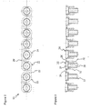
Figure 2 shows a top view of alinear cuvette array 21 according to the invention.Figure 3 shows a cross-section through a plane A-A oflinear cuvette array 21 inFigure 2 . -
Figure 4 shows a cross-sectional view of one of thecuvettes 22 oflinear cuvette array 21 inFigure 2 . -
Figure 5 shows a cross-sectional view of one of thecuvettes 22 oflinear cuvette array 21 inFigure 2 , this cuvette including a foil shaped layer 71 attached to the lower end of the cuvette. -
Figure 6 shows a top view of acuvette holder 42 forming part of a two-dimensional cuvette array according to the invention. -
Figure 7 shows a cross-section through a plane B-B ofcuvette holder 42 inFigure 6 . -
Figure 8 shows a top view of a two-dimensional cuvette array 41 according to the invention. -
Figure 9 shows a cross-section through a plane C-C of two-dimensional cuvette array 41 inFigure 8 . -
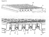
Figure 10 shows a partial cross-section through acuvette holder 42 with acuvette array 21 comprisingcuvettes 22 without positioning means, and asteel matrix 17 imposed on the cuvettes 22 (top). The cross-sectioned part is shown in magnification in the bottom. -
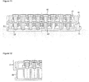
Figure 11 shows a cross-sectional representation of stacked two-dimensional cuvette arrays 41 and 51. -
Figure 12 shows a cross-sectional representation of a two-dimensional cuvette array 31 stacked onto a standard analysis multiwell plate 48. -
Figures 13A to 13E show a top view of a linear cuvette arrays according to the invention. -
Figures 14A to 14G show a cross-section through a plane A-A of linear cuvette arrays according to the invention. -
Figures 2 and 3 show an integrally built,linear array 21 ofcuvettes 22 made of a plastic material. - Every cuvette of
array 21 has the same shape and dimensions and neighboring cuvettes are connected to each other by asingle web single webs - The symmetry axis Y-Y of every
cuvette 22 which forms part ofarray 21 of cuvettes lies substantially in one and the same plane A-A which is a symmetry plane ofcuvette array 21. The upper part of anintermediate cuvette 22 ofarray 21 is connected by a firstsingle web 25 to a neighboring cuvette 23 which lies on one side ofintermediate cuvette 22 and is connected by a secondsingle web 26 to a neighboringcuvette 24 which lies on the opposite side ofintermediate cuvette 22. - The
single webs e.g. cuvette holder 42 described hereinafter, in spite of variations of the length ofcuvette array 21 which are due to different shrinkage coefficients of the different materials used for manufacture ofcuvette arrays 21 by injection molding. Thesesingle webs - At least two of the cuvettes of the
array 21 have means for removably connecting the cuvettes tocuvette holder 42 described hereinafter. These means are an integral part of the cuvette. Preferably, these connecting means arelatches - Preferably, the distribution of cuvettes with connecting means over the array is equitable. If two cuvettes have connecting means preferably the first and the last cuvettes has each connecting means, or second and the last but one cuvette has each connecting means, or the third and the last but two cuvette has each connecting means, and so on.
- In a preferred embodiment, in array of eight cuvettes, the first cuvette, the third cuvette, the fourth, the fifth, the sixth and the eighth cuvette has each connecting means.
- Further preferred arrangements of the connecting means in array of eight cuvettes are shown in
Figure 14 . -
Figure 3 shows a cross-section of one of the cuvettes,e.g. cuvette 22 ofcuvette array 21. As shown byFigure 4 , the cuvette has an upper chamber 27 and a lower chamber 28 which have a common symmetry axis Y-Y which passes through the centers of both chambers. Upper chamber 27 and lower chamber 28 have each a substantially cylindrical shape. The cross-section of upper chamber 27 at the central part thereof is larger than the cross-section of lower chamber 28. - Lower chamber 28 has an open
lower end 33. Upper chamber 27 has an open top end 34 and anannular bottom wall 35. This bottom wall has a centralcircular opening 36 which connects said upper chamber 27 with lower chamber 28. - The
inner surface 37 ofbottom wall 35 is part of a conical surface the cross-section of which forms an angle of about 80 degrees with the symmetry axis Y-Y of the cuvette, so that there is an abrupt change of cross-section between said upper chamber 27 and said lower chamber 28. - The
cuvette array 21 is made by injection molding of a selected first plastic material which is particularly suitable for being used in combination with a second selected material of which a foil shaped layer is made. This layer is adapted to be closely attached to at least one cuvette of the array of cuvettes for covering at least one opening of the cuvette. The same plastic material may be used for said first plastic material and said second plastic material. - The attachment of the foil shaped layer to one or more cuvettes can be effected e.g. by gluing the layer and the one or more cuvettes or by a welding process. Preferred is the attachment of the foil shaped layer by a welding process. The foil attached to one individual cuvette is attached only to this individual cuvette and has no connection with any other cuvette or with a foil attached to a different cuvette.
- The attachment of the layer to the cuvette must ensure a medium tight connection (liquid and/or gas tight connection) of these components.
- Possible uses of such a foil shaped layer include e.g. its use as a filter and/or as a transparent closure (e.g. transparent to ultraviolet irradiation), which must not necessarily have the function of a filter.
- When the foil shaped layer is used as a filter, the filtration process can be effected by use of vacuum or pressure applied to the medium contained in each cuvette of a cuvette array.
- Suitable materials for a foil shaped layer usable as a filter and having a thickness in a range of 10 to 200 micrometer are for instance: polyvinylidenfluorid (PVDF), polycarbonat (PC), polysulfon (PSU), regenerated cellulose, polytetrafluorethylen (PTFE), PET, cyclic olefin copolymers (COC) and filter paper.
- As shown by
Figure 5 such a foil shaped layer is adapted to be closely attached to the lower end of the cuvette.Figure 5 shows acuvette 22 and a foil shaped layer 71 which is closely attached tocuvette 22 for covering the opening of this cuvette at thelower end 33 thereof. - The injection molding apparatus for manufacturing the cuvette array is preferably so configured and dimensioned that injection molding of different materials having different shrinkage coefficients can be carried out with one and the same apparatus.
- In order to obtain a high stability of the assembly formed by a
cuvette array 21 and the above mentioned foil shaped layer, the material of which this layer is made is so selected that properties of the layer are suitable for use with the material of which the cuvettes are made. - On the other hand the materials of the cuvette array and of the foil shaped layer are so selected that they are particularly well adapted for and thereby enable optimization of a particular process carried out with the assembly of cuvette array and foil shaped layer. Such processes are e.g. filtration, diffusion, concentration determination and "microspotting".
- For instance, cuvettes made of a hydrophilic material, e.g. celluloseacetate, are suitably combined with ultrafiltration membranes for carrying out ultrafiltrations in an optimal way. Diffusion processes through artificial membranes are preferably carried out with hydrophobic filtration membranes, which are suitable for being combined by a melting process with cuvette material having similar hydrophobic properties. Filtration processes require hydrophilic or lipophilic properties of the cuvettes and of the filtration membrane attached thereto, and the selection of the materials of these components depends from the properties of the substance to be filtered.
- For processes involving genes or genes, fragments are deposited by microspotting on the foil which is attached to the lower end of the cuvettes of
cuvette array 21. - Following materials are examples of materials which can be used to manufacture cuvette array 21: celluloseacetate, polycarbonate, polyvinylidene fluoride (PVDF), polysulfones, polystyrene, polypropylene (PP) or cyclic olefin copolymers (COC). Materials with similar shrinkage coefficient (in connection with injection molding) and melting properties may also be used for
manufacturing cuvette array 21. -
Figure 6 shows a top view of acuvette holder 42 which can be used to hold a plurality of the above describedcuvette arrays 21 to form a two-dimensional cuvette array 41.Figure 7 shows a cross-section through a plane B-B ofcuvette holder 42 inFigure 6 . - In a preferred
embodiment cuvette holder 42 is of substantially rectangular shape and has four centering ribs located each on the outer surface of one of the corners ofcuvette holder 42. -
Figure 8 shows a top view of a two-dimensional cuvette array 41 according to the invention.Figure 9 shows a cross-section through a plane C-C of two-dimensional cuvette array 41 inFigure 8 . - As can be appreciated from
Figures 8 and 9 , a two-dimensional array 41 of cuvettes according to the invention comprises acuvette holder 42 having amatrix array 43 ofopenings 44 for receivingcuvettes 22 of at least onelinear cuvette array 21 having the above described features. Each of thecuvettes 22 ofcuvette array 21 has a shape and dimensions that snugly fits, also with connecting means, into one ofopenings 44 ofcuvette holder 42. -
Cuvette holder 42 is so configured and dimensioned that two-dimensional array 41 is adapted to be used in a centrifuge. As shown byFigure 9 ,cuvette holder 42 snugly fits into aholder plate 49 of a centrifuge. -
Figure 10 shows acuvette holder 42 with acuvette array 21 and asteel matrix 17 which is imposed on thecuvettes 22 of thecuvette array 21. - For the welding process the
steel matrix 17 is imposed on the cuvettes as shown inFigure 10 . Thesteel matrix 17 comprises wholes whose position and dimensions correspond with the position and dimension of thecuvettes 22 in the array so that thesteel plate 17 may fit on thecuvettes 22. Then, a layer is laid on the open lower ends of the cuvettes and welded, whereby the lower ends form the welding contour 29. A knife in dimension and form equivalent to thesteel matrix 17 punches the layer so that only the layer welded to cuvettes remains. The function of thesteel matrix 17 is to stop the knife of cutting through thecuvette array 21. - As shown by
Figure 11 , two or more two-dimensional cuvette arrays e.g. arrays 41 and 51 each of which has the structure described above with reference toFigures 8 and 9 can be stacked on each other to form a three-dimensional cuvette array. According to the invention, the components of such an array are so configured and dimensioned that cuvettes having the same relative position in their respective holders are accurately positioned one above the other with coincidence of their symmetry axis, one of said cuvettes taking the position of an upper cuvette 61 and the other cuvette taking the position of a lower cuvette 62. In a preferred embodiment a portion of the lower part of each upper cuvette 61 lies within the upper chamber of the corresponding lower cuvette 62 and the lower end of the upper cuvette 61 is at a predetermined distance from the bottom wall of the upper chamber of the lower cuvette 62. - As shown by
Figure 12 , a two-dimensional cuvette array 41 which has the structure described above with reference toFigures 8 and 9 can be stacked also on a standard holder plate 48 for a standard multiwell plate. - According to the invention a system comprising one or more two-dimensional arrays 41, 51, etc. of cuvettes having the above-described structure are used to perform simultaneously diffusion, filtration or detection process steps on a plurality of liquid samples, wherein said samples are e.g. genes, gene fragments, drug substance or precursors of drugs.
- In a preferred embodiment such a system comprises a first two-dimensional cuvette array 41 and a second two-dimensional cuvette array 51, said cuvette arrays 41, 51 are stacked on each other, and the
cuvette holders 42, 52 and thecuvettes 22 of said two-dimensional cuvette arrays 41, 51 are so configured and dimensioned that cuvettes having the same relative position in their respective holders are accurately positioned one above the other with coincidence of their symmetry axis, one of the cuvettes taking the position of an upper cuvette 61 and the other cuvette taking the position of a lower cuvette 62. In a preferred embodiment a portion of the lower part of the upper cuvette 61 lies within the upper chamber of the lower cuvette 62 and the lower end of the upper cuvette 61 is at a predetermined distance from the bottom wall of the upper chamber of the lower cuvette 62. With this arrangement there is no capillary gap between liquid contained in the lower part of the upper cuvette 61 and liquid contained in the upper chamber of the lower cuvette 62. -
Figures 13A to 13E show a top view ofcuvette array 21 with preferred arrangements of the single webs 15,16. -
Figures 14A to 14G show a cross-section through plane A-A of thecuvette arrays 21, with preferred arrangements of the connectingmeans -
11 cuvette array 12 cuvette 13 lower end of cuvette 1214 connecting means 15 positioning means 16 cuvette holder 17 steel matrix 18 lower end of steel matrix 1719 cuvette contour 21 linear cuvette array 22 cuvette 23 cuvette 24 cuvette 25 web 26 web 27 upper chamber 28 lower chamber 29 welding contour 31 latch 32 latch 33 open low end 34 open top end 35 bottom wall 36 opening 37 inner surface of bottom wall 3538 39 41 two- dimensional cuvette array 42 cuvette holder 43 matrix array of openings 44 opening (for receiving cuvettes) 45 46 47 48 standard holder plate for a standard multiwell plate 49 holder plate 51 two-dimensional cuvette array 52 cuvette holder 53 holder plate 61 upper cuvette 62 lower cuvette 71 foil shaped layer - Modifications and alternative embodiments of the invention will be apparent to those skilled in the art in view of the foregoing description. Accordingly, this description is to be construed as illustrative only and is for the purpose of teaching those skilled in the art the best mode of carrying out the invention. Details of the apparatus and of the system described may be varied without departing from the spirit of the invention and the exclusive use of all modifications which come within the scope of the appended claims is reserved.
Claims (14)
- An integrally built, linear array of cuvettes made of a plastic material, every cuvette of the array having the same shape and dimensions, and neighboring cuvettes being connected to each other by a single web, each cuvette of said array has a symmetry axis (Y-Y), the symmetry axis (Y-Y) of every cuvette forming part of said array (21) of cuvettes lies in a plane (A-A) which extends along the length of said cuvette array, said array of cuvettes being characterized in thata) the cuvettes have an open lower end (33),b) at least two cuvettes (22) have means (31, 32) for removably connecting said cuvettes (22) to said cuvette holder, andc) each cuvette is connected by a single web to its neighboring cuvette, said single web is flexible and curved and successive single webs may be on either one of opposite sides of the plane (A-A).
- The linear cuvette array according to claim 1, wherein said array of cuvettes is made of a selected first plastic material which is particularly suitable for being used in combination with the same or a second selected material of which the foil shaped layer (71) is made, said layer being adapted to be closely attached to each cuvette (22) of said array of cuvettes for covering at least one opening of each cuvette (22).
- The linear cuvette array according to claim 2, wherein said first plastic material and said second selected material is COC.
- A two-dimensional array of cuvettes comprising(a) a cuvette holder (42) having a matrix array (43) of openings (44) for receiving cuvettes (22), and(b) at least one linear cuvette array (21) according to any one of the claims 1 to 3, each cuvette (22) of said at least one cuvette array (21) having a shape and dimensions that snugly fits into one of said openings (44) of said cuvette holder (42).
- The two-dimensional array of cuvettes according to claim 4, wherein said cuvette holder (42) and the cuvettes (22) of said at least one linear cuvette array (21) are so configured and dimensioned that two or more cuvette holders (42) carrying each at least one linear cuvette array (21) can be stacked in such a way that cuvettes having the same relative position in their respective holders are accurately
positioned one above the other with coincidence of their symmetry axis, one of said cuvettes taking the position of an upper cuvette (61) and the other cuvette taking the position of a lower cuvette (62), a portion of the lower part of the upper cuvette (61) lying within the upper chamber of the lower cuvette (62) and the lower end of the upper cuvette (61) being at a predetermined distance from the bottom wall of the upper chamber of the lower cuvette (62). - The two-dimensional array of cuvettes according to claim 4 or 5, further comprising a foil (71) which is attached to the lower end of each cuvette (22) for covering the opening (33) of said cuvette at that lower end thereof.
- The two-dimensional array of cuvettes according to claims 6, wherein said foil is a filter.
- The two-dimensional array of cuvettes according to claims 6, wherein said foil is transparent.
- The two-dimensional array of cuvettes according to claims 6, wherein said foil carries genes or gene fragments deposited on said foil by microspotting.
- The two-dimensional array of cuvettes according to claim 4 or 5,
wherein said cuvette holder (42) is of substantially rectangular shape and has four centering ribs located each on the outer surface of one of the corners of said cuvette holder (42). - The two-dimensional array of cuvettes according to claim 4 or 5,
wherein said cuvette holder (42) is so configured and dimensioned that said two-dimensional array (41) of cuvettes is adapted to be used in a centrifuge. - A system for simultaneously performing diffusion or filtration process steps on a plurality of liquid samples, said system comprising one or more two-dimensional arrays of cuvettes according to any of claims 4 to 10.
- The system according to claim 11 comprising a first two-dimensional cuvette array (41) according to claim 4 and a second two-dimensional cuvette array (51) according to claim 4, wherein said cuvette arrays are stacked on each other, and wherein the cuvette holders (42, 52) and the cuvettes (22) of said two-dimensional cuvette arrays (41,51) are so configured and dimensioned that said two-dimensional cuvette arrays (41, 51) can be stacked in such a way that cuvettes having the same relative position in their respective holders are accurately positioned one above the other with coincidence of their symmetry axis, one of said cuvettes taking the position of an upper cuvette (61) and the other cuvette taking the position of a lower cuvette (62), a portion of the lower part of the upper cuvette (61) lying within the upper chamber of the lower cuvette (62) and the lower end of the upper cuvette (61) being at a predetermined distance from the bottom wall of the upper chamber of the lower cuvette (62).
- Linear cuvette arrays, two dimensional cuvette arrays as disclosed in the description and figures
Priority Applications (1)
| Application Number | Priority Date | Filing Date | Title |
|---|---|---|---|
| EP10180535A EP2283923A2 (en) | 2005-11-30 | 2006-11-20 | Linear cuvette array without positioning means |
Applications Claiming Priority (3)
| Application Number | Priority Date | Filing Date | Title |
|---|---|---|---|
| EP05111522 | 2005-11-30 | ||
| EP10180535A EP2283923A2 (en) | 2005-11-30 | 2006-11-20 | Linear cuvette array without positioning means |
| EP20060124369 EP1792656B1 (en) | 2005-11-30 | 2006-11-20 | Integrally built, linear array of cuvettes, two dimensional array of cuvettes and system comprising two or more two-dimensional arrays of cuvettes |
Related Parent Applications (1)
| Application Number | Title | Priority Date | Filing Date |
|---|---|---|---|
| EP06124369.7 Division | 2006-11-20 |
Publications (1)
| Publication Number | Publication Date |
|---|---|
| EP2283923A2 true EP2283923A2 (en) | 2011-02-16 |
Family
ID=37800757
Family Applications (2)
| Application Number | Title | Priority Date | Filing Date |
|---|---|---|---|
| EP10180535A Withdrawn EP2283923A2 (en) | 2005-11-30 | 2006-11-20 | Linear cuvette array without positioning means |
| EP20060124369 Not-in-force EP1792656B1 (en) | 2005-11-30 | 2006-11-20 | Integrally built, linear array of cuvettes, two dimensional array of cuvettes and system comprising two or more two-dimensional arrays of cuvettes |
Family Applications After (1)
| Application Number | Title | Priority Date | Filing Date |
|---|---|---|---|
| EP20060124369 Not-in-force EP1792656B1 (en) | 2005-11-30 | 2006-11-20 | Integrally built, linear array of cuvettes, two dimensional array of cuvettes and system comprising two or more two-dimensional arrays of cuvettes |
Country Status (1)
| Country | Link |
|---|---|
| EP (2) | EP2283923A2 (en) |
Families Citing this family (31)
| Publication number | Priority date | Publication date | Assignee | Title |
|---|---|---|---|---|
| US6692700B2 (en) | 2001-02-14 | 2004-02-17 | Handylab, Inc. | Heat-reduction methods and systems related to microfluidic devices |
| US7829025B2 (en) | 2001-03-28 | 2010-11-09 | Venture Lending & Leasing Iv, Inc. | Systems and methods for thermal actuation of microfluidic devices |
| US8895311B1 (en) | 2001-03-28 | 2014-11-25 | Handylab, Inc. | Methods and systems for control of general purpose microfluidic devices |
| US7010391B2 (en) | 2001-03-28 | 2006-03-07 | Handylab, Inc. | Methods and systems for control of microfluidic devices |
| WO2005011867A2 (en) | 2003-07-31 | 2005-02-10 | Handylab, Inc. | Processing particle-containing samples |
| US8852862B2 (en) | 2004-05-03 | 2014-10-07 | Handylab, Inc. | Method for processing polynucleotide-containing samples |
| US11806718B2 (en) | 2006-03-24 | 2023-11-07 | Handylab, Inc. | Fluorescence detector for microfluidic diagnostic system |
| US7998708B2 (en) | 2006-03-24 | 2011-08-16 | Handylab, Inc. | Microfluidic system for amplifying and detecting polynucleotides in parallel |
| US10900066B2 (en) | 2006-03-24 | 2021-01-26 | Handylab, Inc. | Microfluidic system for amplifying and detecting polynucleotides in parallel |
| DK3088083T3 (en) | 2006-03-24 | 2018-11-26 | Handylab Inc | Method of carrying out PCR down a multi-track cartridge |
| WO2008060604A2 (en) | 2006-11-14 | 2008-05-22 | Handylab, Inc. | Microfluidic system for amplifying and detecting polynucleotides in parallel |
| US8709787B2 (en) | 2006-11-14 | 2014-04-29 | Handylab, Inc. | Microfluidic cartridge and method of using same |
| US8182763B2 (en) | 2007-07-13 | 2012-05-22 | Handylab, Inc. | Rack for sample tubes and reagent holders |
| US9186677B2 (en) | 2007-07-13 | 2015-11-17 | Handylab, Inc. | Integrated apparatus for performing nucleic acid extraction and diagnostic testing on multiple biological samples |
| AU2008276211B2 (en) | 2007-07-13 | 2015-01-22 | Handylab, Inc. | Polynucleotide capture materials, and methods of using same |
| US8287820B2 (en) | 2007-07-13 | 2012-10-16 | Handylab, Inc. | Automated pipetting apparatus having a combined liquid pump and pipette head system |
| US9618139B2 (en) | 2007-07-13 | 2017-04-11 | Handylab, Inc. | Integrated heater and magnetic separator |
| US8105783B2 (en) | 2007-07-13 | 2012-01-31 | Handylab, Inc. | Microfluidic cartridge |
| USD787087S1 (en) | 2008-07-14 | 2017-05-16 | Handylab, Inc. | Housing |
| FR2965622A1 (en) * | 2010-10-05 | 2012-04-06 | Stago Diagnostica | REACTION CUP FOR AUTOMATIC CHEMICAL OR BIOLOGICAL ANALYSIS APPARATUS |
| ES2769028T3 (en) | 2011-04-15 | 2020-06-24 | Becton Dickinson Co | Real-time scanning microfluidic thermocycler |
| USD692162S1 (en) | 2011-09-30 | 2013-10-22 | Becton, Dickinson And Company | Single piece reagent holder |
| ES2645966T3 (en) | 2011-09-30 | 2017-12-11 | Becton, Dickinson And Company | Unified test strip |
| CN104040238B (en) | 2011-11-04 | 2017-06-27 | 汉迪拉布公司 | Polynucleotides sample preparation apparatus |
| AU2013214849B2 (en) | 2012-02-03 | 2016-09-01 | Becton, Dickinson And Company | External files for distribution of molecular diagnostic tests and determination of compatibility between tests |
| US10220392B2 (en) | 2013-03-15 | 2019-03-05 | Becton, Dickinson And Company | Process tube and carrier tray |
| USD759835S1 (en) | 2013-03-15 | 2016-06-21 | Becton, Dickinson And Company | Process tube strip |
| US11865544B2 (en) | 2013-03-15 | 2024-01-09 | Becton, Dickinson And Company | Process tube and carrier tray |
| EP2969211B1 (en) | 2013-03-15 | 2019-06-26 | Becton, Dickinson and Company | Process tube and carrier tray |
| USD762873S1 (en) | 2013-03-15 | 2016-08-02 | Becton, Dickinson And Company | Process tube |
| EP3342485B1 (en) * | 2017-01-02 | 2020-07-08 | Thinxxs Microtechnology Ag | Holder for reagent elements |
Citations (1)
| Publication number | Priority date | Publication date | Assignee | Title |
|---|---|---|---|---|
| EP1232792A1 (en) | 2001-02-20 | 2002-08-21 | F. Hoffmann-La Roche Ag | Linear cuvette array, a two-dimensional cuvette array built therewith and a system comprising such two-dimensional cuvette arrays |
Family Cites Families (1)
| Publication number | Priority date | Publication date | Assignee | Title |
|---|---|---|---|---|
| AT500523B1 (en) * | 2002-04-30 | 2007-09-15 | Greiner Bio One Gmbh | DEVICE FOR PROTEIN CRYSTALLIZATION |
-
2006
- 2006-11-20 EP EP10180535A patent/EP2283923A2/en not_active Withdrawn
- 2006-11-20 EP EP20060124369 patent/EP1792656B1/en not_active Not-in-force
Patent Citations (1)
| Publication number | Priority date | Publication date | Assignee | Title |
|---|---|---|---|---|
| EP1232792A1 (en) | 2001-02-20 | 2002-08-21 | F. Hoffmann-La Roche Ag | Linear cuvette array, a two-dimensional cuvette array built therewith and a system comprising such two-dimensional cuvette arrays |
Also Published As
| Publication number | Publication date |
|---|---|
| EP1792656A1 (en) | 2007-06-06 |
| EP1792656B1 (en) | 2011-11-02 |
Similar Documents
| Publication | Publication Date | Title |
|---|---|---|
| EP1792656B1 (en) | Integrally built, linear array of cuvettes, two dimensional array of cuvettes and system comprising two or more two-dimensional arrays of cuvettes | |
| EP1232792B1 (en) | Linear cuvette array, a two-dimensional cuvette array built therewith and a system comprising such two-dimensional cuvette arrays | |
| US6943009B2 (en) | Multi-well assembly for growing cultures in-vitro | |
| KR100923482B1 (en) | Well for processing a fluid | |
| US5679310A (en) | High surface area multiwell test plate | |
| US6391241B1 (en) | Method of manufacture for a multiwell plate and/or filter plate | |
| US7785466B1 (en) | Membrane filtered pipette tip | |
| EP1515804B1 (en) | Universal multiwell filtration plate | |
| JP2009542208A (en) | High density permeable support for high throughput screening | |
| US7063216B2 (en) | Underdrain useful in the construction of a filtration device | |
| US8182766B2 (en) | Universal filter plate | |
| US8753588B2 (en) | Support and stand-off ribs for underdrain for multi-well device | |
| EP2169383A1 (en) | Body for flow through cuvettes and use thereof | |
| JP4406421B2 (en) | Linear cuvette array without positioning means | |
| EP1724019B1 (en) | Receiver plate with multiple cross-sections | |
| US20030226796A1 (en) | Modular system for separating components of a liquid sample | |
| US20020195386A1 (en) | Filtration and separation apparatus and method of assembly | |
| EP1705474B1 (en) | Method for determining lipophilicity | |
| US7527975B2 (en) | Determination of high lipophilicity values | |
| WO2025235549A2 (en) | Microtube insert device |
Legal Events
| Date | Code | Title | Description |
|---|---|---|---|
| PUAI | Public reference made under article 153(3) epc to a published international application that has entered the european phase |
Free format text: ORIGINAL CODE: 0009012 |
|
| AC | Divisional application: reference to earlier application |
Ref document number: 1792656 Country of ref document: EP Kind code of ref document: P |
|
| AK | Designated contracting states |
Kind code of ref document: A2 Designated state(s): AT BE BG CH CY CZ DE DK EE ES FI FR GB GR HU IE IS IT LI LT LU LV MC NL PL PT RO SE SI SK TR |
|
| STAA | Information on the status of an ep patent application or granted ep patent |
Free format text: STATUS: THE APPLICATION HAS BEEN WITHDRAWN |
|
| 18W | Application withdrawn |
Effective date: 20110920 |