EP2283775A1 - Ultrasound system and method for performing vessel labeling - Google Patents
Ultrasound system and method for performing vessel labeling Download PDFInfo
- Publication number
- EP2283775A1 EP2283775A1 EP10170229A EP10170229A EP2283775A1 EP 2283775 A1 EP2283775 A1 EP 2283775A1 EP 10170229 A EP10170229 A EP 10170229A EP 10170229 A EP10170229 A EP 10170229A EP 2283775 A1 EP2283775 A1 EP 2283775A1
- Authority
- EP
- European Patent Office
- Prior art keywords
- vessel
- ultrasound
- vessels
- segmentation
- segmented
- Prior art date
- Legal status (The legal status is an assumption and is not a legal conclusion. Google has not performed a legal analysis and makes no representation as to the accuracy of the status listed.)
- Granted
Links
Images



Classifications
-
- A—HUMAN NECESSITIES
- A61—MEDICAL OR VETERINARY SCIENCE; HYGIENE
- A61B—DIAGNOSIS; SURGERY; IDENTIFICATION
- A61B8/00—Diagnosis using ultrasonic, sonic or infrasonic waves
- A61B8/13—Tomography
- A61B8/14—Echo-tomography
-
- A—HUMAN NECESSITIES
- A61—MEDICAL OR VETERINARY SCIENCE; HYGIENE
- A61B—DIAGNOSIS; SURGERY; IDENTIFICATION
- A61B5/00—Measuring for diagnostic purposes; Identification of persons
- A61B5/02—Detecting, measuring or recording for evaluating the cardiovascular system, e.g. pulse, heart rate, blood pressure or blood flow
- A61B5/02007—Evaluating blood vessel condition, e.g. elasticity, compliance
-
- A—HUMAN NECESSITIES
- A61—MEDICAL OR VETERINARY SCIENCE; HYGIENE
- A61B—DIAGNOSIS; SURGERY; IDENTIFICATION
- A61B8/00—Diagnosis using ultrasonic, sonic or infrasonic waves
- A61B8/48—Diagnostic techniques
- A61B8/483—Diagnostic techniques involving the acquisition of a 3D volume of data
-
- G—PHYSICS
- G06—COMPUTING OR CALCULATING; COUNTING
- G06T—IMAGE DATA PROCESSING OR GENERATION, IN GENERAL
- G06T19/00—Manipulating three-dimensional [3D] models or images for computer graphics
- G06T19/20—Editing of three-dimensional [3D] images, e.g. changing shapes or colours, aligning objects or positioning parts
-
- G—PHYSICS
- G06—COMPUTING OR CALCULATING; COUNTING
- G06T—IMAGE DATA PROCESSING OR GENERATION, IN GENERAL
- G06T7/00—Image analysis
- G06T7/10—Segmentation; Edge detection
- G06T7/12—Edge-based segmentation
-
- G—PHYSICS
- G06—COMPUTING OR CALCULATING; COUNTING
- G06T—IMAGE DATA PROCESSING OR GENERATION, IN GENERAL
- G06T7/00—Image analysis
- G06T7/10—Segmentation; Edge detection
- G06T7/174—Segmentation; Edge detection involving the use of two or more images
-
- G—PHYSICS
- G06—COMPUTING OR CALCULATING; COUNTING
- G06T—IMAGE DATA PROCESSING OR GENERATION, IN GENERAL
- G06T2207/00—Indexing scheme for image analysis or image enhancement
- G06T2207/10—Image acquisition modality
- G06T2207/10132—Ultrasound image
- G06T2207/10136—3D ultrasound image
-
- G—PHYSICS
- G06—COMPUTING OR CALCULATING; COUNTING
- G06T—IMAGE DATA PROCESSING OR GENERATION, IN GENERAL
- G06T2207/00—Indexing scheme for image analysis or image enhancement
- G06T2207/20—Special algorithmic details
- G06T2207/20112—Image segmentation details
- G06T2207/20164—Salient point detection; Corner detection
-
- G—PHYSICS
- G06—COMPUTING OR CALCULATING; COUNTING
- G06T—IMAGE DATA PROCESSING OR GENERATION, IN GENERAL
- G06T2207/00—Indexing scheme for image analysis or image enhancement
- G06T2207/30—Subject of image; Context of image processing
- G06T2207/30004—Biomedical image processing
- G06T2207/30101—Blood vessel; Artery; Vein; Vascular
Definitions
- the present disclosure generally relates to ultrasound systems, and more particularly to an ultrasound system and method for automatically performing vessel labeling.
- An ultrasound system has been extensively used for acquiring internal information of a target object due to its non-invasive and non-destructive nature. Since the ultrasound system may provide a high resolution image without any surgical treatment, it has proven to be very helpful in the medical profession.
- the ultrasound system may provide 3-dimensional ultrasound images including clinical information such as spatial information and anatomical information, which 2-dimensional ultrasound images do not include.
- the ultrasound system may operate to transmit an ultrasound signal to a target object, receive the ultrasound signal reflected from the target object (i.e., ultrasound echo signal) and acquire ultrasound data.
- the ultrasound system may form volume data by using the acquired ultrasound data and provide a 3-dimensional image through rendering of the formed volume data.
- the ultrasound system may perform segmentation on the 3-dimensional ultrasound image and extract an object of interest from the 3-dimensional ultrasound image.
- segmentation may be performed on the 3-dimensional ultrasound image and extract an object of interest from the 3-dimensional ultrasound image.
- the ultrasound system comprises: an ultrasound data acquisition unit configured to transmit an ultrasound signal to a target object including vessels, receive an ultrasound echo signal reflected from the target object and form ultrasound data corresponding to the target object; a volume data forming unit configured to form volume data based on the ultrasound data; and a processor configured to form a 3-dimensional ultrasound image based on the volume data, perform vessel segmentation on the 3-dimensional ultrasound image to provide at least one segmented image including at least one segmented vessel, detect at least one vessel junction from the at least one segmented vessel and perform vessel labeling on the at least one segmented image based on the detected at least one vessel junction.
- a method of performing segmentation of vessels comprises: a) transmitting an ultrasound signal to a target object including vessels and receiving an ultrasound echo signal reflected from the target object to thereby form ultrasound data corresponding to the target object; b) forming volume data based on the ultrasound data; c) forming a 3-dimensional ultrasound image based on the volume data; d) performing vessel segmentation on the 3-dimensional ultrasound image to provide at least one segmented image including at least one segmented vessel; e) detecting at least one vessel junction from the at least one segmented vessel; and f) performing vessel labeling on the at least one segmented image based on the detected at least one vessel junction.
- FIG. 1 is a block diagram showing an illustrative embodiment of an ultrasound system 100.
- the ultrasound system 100 comprises an ultrasound data acquisition unit 110, a volume data forming unit 120, a processor 130, a display unit 140 and a control unit 150.
- the ultrasound data acquisition unit 110 may be operable to transmit an ultrasound signal to a target object, and receive the ultrasound signal (i.e., ultrasound echo signal) reflected from the target object to thereby acquire ultrasound data.
- an ultrasound signal i.e., ultrasound echo signal
- FIG. 2 is a block diagram showing an illustrative embodiment of the ultrasound data acquisition unit 110.
- the ultrasound data acquisition unit 110 may include a transmit signal forming unit 210, an ultrasound probe 220 including a plurality of transducer elements (not shown), a beam former 230 and an ultrasound data forming unit 240.
- the transmit signal forming unit 210 may be operable to form a transmit signal to be applied to each of the transducer elements of the ultrasound probe 220.
- the positions and focusing points of the transducer elements may be considered in forming the transmit signal.
- the transmit signal may include a transmit signal for acquiring a plurality of frames of the target object.
- the ultrasound probe 220 may operate to convert the transmit signal provided by the transmit signal forming unit 210 into an ultrasound signal and transmit it to the target object.
- the ultrasound probe 220 may further operate to receive the ultrasound echo signal reflected from the target object and form a receive signal.
- the beam former 230 may be configured to form a digital signal through analog-to-digital conversion of the receive signal provided by the ultrasound probe 220.
- the beam former 230 may operate to perform receive-focusing upon the digital signal in consideration of the positions and focusing points of the transducer elements, and form a receive-focused signal thereby.
- the ultrasound data forming unit 240 may be configured to form ultrasound data of the target object using the receive-focused signal provided by the beam former 230.
- the ultrasound data may comprise RF (radio frequency) data and IQ (in-phase/quardrature) data.
- the volume data forming unit 120 may operate to form volume data by using the ultrasound data provided by the ultrasound acquisition unit 110.
- the volume data may comprise a plurality of frames and a plurality of voxels having brightness values.
- the processor 130 may operate to form a 3-dimensional ultrasound image including vessels in the target object by using the volume data provided by the volume data forming unit 120, and perform segmentation of the vessels and vessel labeling by using the 3-dimensional ultrasound image.
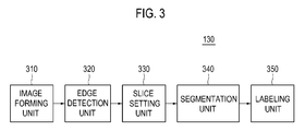
- FIG. 3 is a block diagram showing an illustrative embodiment of the processor 130.
- the processor 130 comprises an image forming unit 310, an edge detection unit 320, a slice setting unit 330, a segmentation unit 340 and a labeling unit 350.
- the image forming unit 310 may operate to form the 3-dimensional ultrasound image through rendering of the volume data provided by the volume data forming unit 120.
- the rendering may comprise ray-casting rendering, surface rendering, etc.
- the edge detection unit 320 may operate to detect vessel edges through performing edge detection on the 3-dimensional ultrasound image provided by the image forming unit 310.
- the vessel edges may be detected by using an edge mask such as a Sobel mask, a Prewitt mask, a Robert mask, a Canny mask, etc.
- the vessel edges may be detected from the difference of eigen values by using a structure tensor.
- the slice setting unit 330 may operate to set a plurality of slices S 0 to S n on the 3-dimensional ultrasound image in which the vessel edges were detected, as illustrated in FIG. 4 .
- the plurality of slices may comprise slices corresponding to the plurality of frames.
- the segmentation unit 340 may be configured to perform segmentation of the vessels based on a degree of registration between the respective vessels on the adjacent slices. In one embodiment, the segmentation unit 340 may operate to compare the location of vessels on adjacent slices by using the vessel edges and perform segmentation of the vessels. Following is illustrative operation of the segmentation unit 340 with reference to FIG. 4 to 6 .
- the segmentation unit 340 may operate to analyze a first slice S 1 and detect vessel edges VE 11 , VE 12 on the first slice S 1 .
- the segmentation unit 340 may operate to analyze a second slice S 2 and detect vessel edges VE 21 , VE 22 on the second slice S 2 .
- the segmentation unit 340 may operate to detect location difference between the vessel edges on the adjacent slices (i.e., the first slice S 1 and the second slice S 2 ), as illustrated in FIG. 5 .
- the segmentation unit 340 may operate to detect the location difference between the vessel edge VE 11 of the first slice S 1 and the vessel edge VE 21 of the second slice S 2 , as well as the location difference between the vessel edge VE 11 of the first slice S 1 and the vessel edge VE 22 of the second slice S 2 .
- the segmentation unit 340 may operate to detect the location difference between the vessel edge VE 12 of the first slice S 1 and the vessel edge VE 21 of the second slice S 2 , as well as the location difference between the vessel edge VE 12 of the first slice S 1 and the vessel edge VE 22 of the second slice S 2 .
- the segmentation unit 134 may connect the vessel edge VE 21 of the second slice S 2 with the vessel edge VE 11 of the first slice S 1 , and connect the vessel edge VE 22 of the second slice S 2 with the vessel edge VE 12 of the first slice S 1 .
- the segmentation unit 340 may perform the same operation with respect to a third slice S 3 and a fourth slice S 4 , as described above.
- the segmentation unit 340 may operate to analyze a fifth slice S 5 and detect a vessel edge VE 5 on the fifth slice S 5 .
- the segmentation unit 134 may operate to detect the location difference between the vessel edges on the adjacent slices (i.e., the fourth slice S 4 and the fifth slice S 5 ).
- the segmentation unit 340 may connect the vessel edge VE 5 of the fifth slice S 5 with the vessel edges VE 41 , VE 41 of the fourth slice S 4 .
- the segmentation unit 340 may operate to analyze a sixth slice S 6 and detect a vessel edge VE 6 on the sixth slice S 6 .
- the segmentation unit 340 may operate to detect the location difference between the vessel edges on the adjacent slices (i.e., the fifth slice S 5 and the sixth slice S 6 ). In case that the location difference between the vessel edge VE 5 of the fifth slice S 5 and the vessel edge VE 6 of the sixth slice S 6 are equal to or less than the predetermined threshold, the segmentation unit 340 may connect the vessel edge VE 6 of the sixth slice S 6 with the vessel edge VE 5 of the fifth slice S 5 .
- the segmentation unit 340 may perform the same operation with respect to a seventh slice S 7 to an nth slice S n as described above in order to perform segmentation of the vessels, as illustrated in FIG. 6 .
- segmentation of vessel is performed by setting a plurality of slices on the 3-dimensional ultrasound image and calculating location differences between the edges of the vessels on each adjacent pair of the slices, the present invention is certainly not limited thereto. In another embodiment, segmentation of vessel may be performed using another wee-known method of segmentation.
- the labeling unit 350 may operate to detect vessel junctions using edges of vessels on a respective plurality of slices after segmentation of vessel and perform vessel labeling based on the detected vessel junctions.
- labeling unit 135 may operate to detect a vessel junction VJ analyzing a respective plurality of slices, as illustrated in FIG 7 .
- the vessel junction VJ may comprise a junction where one vessel diverges to at least two vessels or at least two vessels join and merge to one vessel.
- the labeling unit 350 may operate to perform vessel labeling based on the vessel junction VJ.
- vessel labeling is performed based on the vessel junction VJ with number, the present invention is certainly not limited thereto.
- vessel labeling may be performed with at least one of number, text and color.
- the display unit 140 may operate to display the 3-dimensional ultrasound image formed by the processor.
- the display unit 140 may further operate to display the 3-dimensional ultrasound image on which the processor 130 performed segmentation of the vessels.
- the display unit 140 may include a liquid crystal display (LCD), a cathode ray tube (CRT) or any other device capable of displaying an image.
- LCD liquid crystal display
- CRT cathode ray tube
- the control unit 150 may operate to control acquisition of the ultrasound data, and formation of the volume data and the 3-dimensional ultrasound image.
- the control unit 150 may further operate to control image processing of the 3-dimensional ultrasound image (i.e., segmentation of the vessels and vessel labeling).
Landscapes
- Health & Medical Sciences (AREA)
- Life Sciences & Earth Sciences (AREA)
- Engineering & Computer Science (AREA)
- Physics & Mathematics (AREA)
- General Health & Medical Sciences (AREA)
- Public Health (AREA)
- Pathology (AREA)
- Veterinary Medicine (AREA)
- Biomedical Technology (AREA)
- Heart & Thoracic Surgery (AREA)
- Medical Informatics (AREA)
- Molecular Biology (AREA)
- Surgery (AREA)
- Animal Behavior & Ethology (AREA)
- Biophysics (AREA)
- Theoretical Computer Science (AREA)
- General Physics & Mathematics (AREA)
- Nuclear Medicine, Radiotherapy & Molecular Imaging (AREA)
- Radiology & Medical Imaging (AREA)
- Computer Vision & Pattern Recognition (AREA)
- Vascular Medicine (AREA)
- Cardiology (AREA)
- Physiology (AREA)
- Software Systems (AREA)
- General Engineering & Computer Science (AREA)
- Computer Hardware Design (AREA)
- Computer Graphics (AREA)
- Architecture (AREA)
- Ultra Sonic Daignosis Equipment (AREA)
- Image Processing (AREA)
Abstract
Description
- The present application claims priority from Korean Patent Application No.
10-2009-0073365 - The present disclosure generally relates to ultrasound systems, and more particularly to an ultrasound system and method for automatically performing vessel labeling.
- An ultrasound system has been extensively used for acquiring internal information of a target object due to its non-invasive and non-destructive nature. Since the ultrasound system may provide a high resolution image without any surgical treatment, it has proven to be very helpful in the medical profession.
- Generally, the ultrasound system may provide 3-dimensional ultrasound images including clinical information such as spatial information and anatomical information, which 2-dimensional ultrasound images do not include. The ultrasound system may operate to transmit an ultrasound signal to a target object, receive the ultrasound signal reflected from the target object (i.e., ultrasound echo signal) and acquire ultrasound data. The ultrasound system may form volume data by using the acquired ultrasound data and provide a 3-dimensional image through rendering of the formed volume data.
- Also, the ultrasound system may perform segmentation on the 3-dimensional ultrasound image and extract an object of interest from the 3-dimensional ultrasound image. However, if a structure of vessel is complicated after performing segmentation, then it is difficult to recognize a specific vessel among many vessels as well as to locate vessel connection points (or junctions).
- There are disclosed embodiments of an ultrasound system and a method adapted to perform segmentation of vessel and automatically labeling on the vessel. In one embodiment, by way of non-limiting example, the ultrasound system comprises: an ultrasound data acquisition unit configured to transmit an ultrasound signal to a target object including vessels, receive an ultrasound echo signal reflected from the target object and form ultrasound data corresponding to the target object; a volume data forming unit configured to form volume data based on the ultrasound data; and a processor configured to form a 3-dimensional ultrasound image based on the volume data, perform vessel segmentation on the 3-dimensional ultrasound image to provide at least one segmented image including at least one segmented vessel, detect at least one vessel junction from the at least one segmented vessel and perform vessel labeling on the at least one segmented image based on the detected at least one vessel junction.
- In another embodiment, a method of performing segmentation of vessels, comprises: a) transmitting an ultrasound signal to a target object including vessels and receiving an ultrasound echo signal reflected from the target object to thereby form ultrasound data corresponding to the target object; b) forming volume data based on the ultrasound data; c) forming a 3-dimensional ultrasound image based on the volume data; d) performing vessel segmentation on the 3-dimensional ultrasound image to provide at least one segmented image including at least one segmented vessel; e) detecting at least one vessel junction from the at least one segmented vessel; and f) performing vessel labeling on the at least one segmented image based on the detected at least one vessel junction.
- The Summary is provided to introduce a selection of concepts in a simplified form that are further described below in the Detailed Description. This Summary is not intended to identify key or essential features of the claimed subject matter, nor is it intended to be used in determining the scope of the claimed subject matter.
-
- FIG. 1
- is a block diagram showing an illustrative embodiment of an ultrasound system.
- FIG. 2
- is a block diagram showing an illustrative embodiment of an ultrasound data acquisition unit.
- FIG. 3
- is a block diagram showing an illustrative embodiment of a processor.
- FIG. 4
- is a schematic diagram showing an example of a plurality of slices and vessel edges.
- FIG. 5
- is a schematic diagram showing an example of location difference between vessel edges on adjacent slices.
- FIG. 6
- is a schematic diagram showing an example of segmentation of vessel.
- FIG. 7
- is a schematic diagram showing an example of labeled vessels.
- A detailed description may be provided with reference to the accompanying drawings.
-
FIG. 1 is a block diagram showing an illustrative embodiment of anultrasound system 100. Theultrasound system 100 comprises an ultrasounddata acquisition unit 110, a volumedata forming unit 120, aprocessor 130, adisplay unit 140 and acontrol unit 150. - The ultrasound
data acquisition unit 110 may be operable to transmit an ultrasound signal to a target object, and receive the ultrasound signal (i.e., ultrasound echo signal) reflected from the target object to thereby acquire ultrasound data. -
FIG. 2 is a block diagram showing an illustrative embodiment of the ultrasounddata acquisition unit 110. The ultrasounddata acquisition unit 110 may include a transmitsignal forming unit 210, anultrasound probe 220 including a plurality of transducer elements (not shown), a beam former 230 and an ultrasounddata forming unit 240. - The transmit
signal forming unit 210 may be operable to form a transmit signal to be applied to each of the transducer elements of theultrasound probe 220. By way of a non-limiting example, the positions and focusing points of the transducer elements may be considered in forming the transmit signal. In one embodiment, the transmit signal may include a transmit signal for acquiring a plurality of frames of the target object. - The
ultrasound probe 220 may operate to convert the transmit signal provided by the transmitsignal forming unit 210 into an ultrasound signal and transmit it to the target object. Theultrasound probe 220 may further operate to receive the ultrasound echo signal reflected from the target object and form a receive signal. - The beam former 230 may be configured to form a digital signal through analog-to-digital conversion of the receive signal provided by the
ultrasound probe 220. The beam former 230 may operate to perform receive-focusing upon the digital signal in consideration of the positions and focusing points of the transducer elements, and form a receive-focused signal thereby. - The ultrasound
data forming unit 240 may be configured to form ultrasound data of the target object using the receive-focused signal provided by the beam former 230. In one embodiment, the ultrasound data may comprise RF (radio frequency) data and IQ (in-phase/quardrature) data. - Referring back to
FIG. 1 , the volumedata forming unit 120 may operate to form volume data by using the ultrasound data provided by theultrasound acquisition unit 110. The volume data may comprise a plurality of frames and a plurality of voxels having brightness values. - The
processor 130 may operate to form a 3-dimensional ultrasound image including vessels in the target object by using the volume data provided by the volumedata forming unit 120, and perform segmentation of the vessels and vessel labeling by using the 3-dimensional ultrasound image. -
FIG. 3 is a block diagram showing an illustrative embodiment of theprocessor 130. Theprocessor 130 comprises animage forming unit 310, anedge detection unit 320, aslice setting unit 330, asegmentation unit 340 and alabeling unit 350. - The
image forming unit 310 may operate to form the 3-dimensional ultrasound image through rendering of the volume data provided by the volumedata forming unit 120. In one embodiment, the rendering may comprise ray-casting rendering, surface rendering, etc. - The
edge detection unit 320 may operate to detect vessel edges through performing edge detection on the 3-dimensional ultrasound image provided by theimage forming unit 310. In one embodiment, the vessel edges may be detected by using an edge mask such as a Sobel mask, a Prewitt mask, a Robert mask, a Canny mask, etc. Also, the vessel edges may be detected from the difference of eigen values by using a structure tensor. - The
slice setting unit 330 may operate to set a plurality of slices S0 to Sn on the 3-dimensional ultrasound image in which the vessel edges were detected, as illustrated inFIG. 4 . In one embodiment, the plurality of slices may comprise slices corresponding to the plurality of frames. - The
segmentation unit 340 may be configured to perform segmentation of the vessels based on a degree of registration between the respective vessels on the adjacent slices. In one embodiment, thesegmentation unit 340 may operate to compare the location of vessels on adjacent slices by using the vessel edges and perform segmentation of the vessels. Following is illustrative operation of thesegmentation unit 340 with reference toFIG. 4 to 6 . - The
segmentation unit 340 may operate to analyze a first slice S1 and detect vessel edges VE11, VE12 on the first slice S1. - The
segmentation unit 340 may operate to analyze a second slice S2 and detect vessel edges VE21, VE22 on the second slice S2. Thesegmentation unit 340 may operate to detect location difference between the vessel edges on the adjacent slices (i.e., the first slice S1 and the second slice S2), as illustrated inFIG. 5 . Specifically, the segmentation unit 340 may operate to detect the location difference between the vessel edge VE11 of the first slice S1 and the vessel edge VE21 of the second slice S2, as well as the location difference between the vessel edge VE11 of the first slice S1 and the vessel edge VE22 of the second slice S2. Further, the segmentation unit 340 may operate to detect the location difference between the vessel edge VE12 of the first slice S1 and the vessel edge VE21 of the second slice S2, as well as the location difference between the vessel edge VE12 of the first slice S1 and the vessel edge VE22 of the second slice S2. In case that the location difference between the vessel edge VE11 of the first slice S1 and the vessel edge VE21 of the second slice S2 and the location difference between the vessel edge VE12 of the first slice S1 and the vessel edge VE22 of the second slice S2 are equal to or less than a predetermined threshold, and the location difference between the vessel edge VE11 of the first slice S1 and the vessel edge VE22 of the second slice S2 and the location difference between the vessel edge VE12 of the first slice S1 and the vessel edge VE21 of the second slice S2 are more than the predetermined threshold, the segmentation unit 134 may connect the vessel edge VE21 of the second slice S2 with the vessel edge VE11 of the first slice S1, and connect the vessel edge VE22 of the second slice S2 with the vessel edge VE12 of the first slice S1. Thesegmentation unit 340 may perform the same operation with respect to a third slice S3 and a fourth slice S4, as described above. - The
segmentation unit 340 may operate to analyze a fifth slice S5 and detect a vessel edge VE5 on the fifth slice S5. The segmentation unit 134 may operate to detect the location difference between the vessel edges on the adjacent slices (i.e., the fourth slice S4 and the fifth slice S5). In case that the location difference between the vessel edge VE41 of the fourth slice S4 and the vessel edge VE5 of the fifth slice S5 and the location difference between the vessel edge VE42 of the fourth slice S4 and the vessel edge VE5 of the fifth slice S5 are equal to or less than the predetermined threshold, thesegmentation unit 340 may connect the vessel edge VE5 of the fifth slice S5 with the vessel edges VE41, VE41 of the fourth slice S4. - The
segmentation unit 340 may operate to analyze a sixth slice S6 and detect a vessel edge VE6 on the sixth slice S6. Thesegmentation unit 340 may operate to detect the location difference between the vessel edges on the adjacent slices (i.e., the fifth slice S5 and the sixth slice S6). In case that the location difference between the vessel edge VE5 of the fifth slice S5 and the vessel edge VE6 of the sixth slice S6 are equal to or less than the predetermined threshold, thesegmentation unit 340 may connect the vessel edge VE6 of the sixth slice S6 with the vessel edge VE5 of the fifth slice S5. - The
segmentation unit 340 may perform the same operation with respect to a seventh slice S7 to an nth slice Sn as described above in order to perform segmentation of the vessels, as illustrated inFIG. 6 . - Although in the aforementioned embodiment, segmentation of vessel is performed by setting a plurality of slices on the 3-dimensional ultrasound image and calculating location differences between the edges of the vessels on each adjacent pair of the slices, the present invention is certainly not limited thereto. In another embodiment, segmentation of vessel may be performed using another wee-known method of segmentation.
- The
labeling unit 350 may operate to detect vessel junctions using edges of vessels on a respective plurality of slices after segmentation of vessel and perform vessel labeling based on the detected vessel junctions. In one embodiment, labeling unit 135 may operate to detect a vessel junction VJ analyzing a respective plurality of slices, as illustrated inFIG 7 . The vessel junction VJ may comprise a junction where one vessel diverges to at least two vessels or at least two vessels join and merge to one vessel. Thelabeling unit 350 may operate to perform vessel labeling based on the vessel junction VJ. Although inFIG 7 , vessel labeling is performed based on the vessel junction VJ with number, the present invention is certainly not limited thereto. In another embodiment, vessel labeling may be performed with at least one of number, text and color. - Referring back to
FIG. 1 , thedisplay unit 140 may operate to display the 3-dimensional ultrasound image formed by the processor. Thedisplay unit 140 may further operate to display the 3-dimensional ultrasound image on which theprocessor 130 performed segmentation of the vessels. In one embodiment, thedisplay unit 140 may include a liquid crystal display (LCD), a cathode ray tube (CRT) or any other device capable of displaying an image. - The
control unit 150 may operate to control acquisition of the ultrasound data, and formation of the volume data and the 3-dimensional ultrasound image. Thecontrol unit 150 may further operate to control image processing of the 3-dimensional ultrasound image (i.e., segmentation of the vessels and vessel labeling). - Although embodiments have been described with reference to a number of illustrative embodiments thereof, it should be understood that numerous other modifications and embodiments can be devised by those skilled in the art that will fall within the spirit and scope of the principles of this disclosure. More particularly, numerous variations and modifications are possible in the component parts and/or arrangements within the scope of the disclosure, the drawings and the appended claims. In addition to variations and modifications in the component parts and/or arrangements, alternative uses will also be apparent to those skilled in the art.
Claims (6)
- An ultrasound system, comprising:an ultrasound data acquisition unit configured to transmit an ultrasound signal to a target object including vessels, receive an ultrasound echo signal reflected from the target object and form ultrasound data corresponding to the target object;a volume data forming unit configured to form volume data based on the ultrasound data; anda processor configured to form a 3-dimensional ultrasound image based on the volume data, perform vessel segmentation on the 3-dimensional ultrasound image to provide at least one segmented image including at least one segmented vessel, detect at least one vessel junction from the at least one segmented vessel and perform vessel labeling on the at least one segmented image based on the detected at least one vessel junction.
- The ultrasound system of Claim 1, wherein the processor further comprises:a slice setting unit configured to set a plurality of slices on the 3-dimensional ultrasound image;an edge detection unit configured to detect edges of the vessels on each of the plurality of slices; anda segmentation unit configured to calculate differences in location between the edges of the vessels on each adjacent pair of the slices and perform segmentation of the vessels based on the location differences.
- The ultrasound system of Claim 1, wherein the processor comprises a labeling unit configured to perform vessel labeling on the at least one segmented image using at least one of number, text and color.
- A method of performing segmentation of vessels, comprising:a) transmitting an ultrasound signal to a target object including vessels and receiving an ultrasound echo signal reflected from the target object to thereby form ultrasound data corresponding to the target object;b) forming volume data based on the ultrasound data;c) forming a 3-dimensional ultrasound image based on the volume data;d) performing vessel segmentation on the 3-dimensional ultrasound image to provide at least one segmented image including at least one segmented vessel;e) detecting at least one vessel junction from the at least one segmented vessel; andf) performing vessel labeling on the at least one segmented image based on the detected at least one vessel junction.
- The method of Claim 4, wherein the performing segmentation of the vessels comprises:setting a plurality of slices on the 3-dimensional ultrasound image;detecting edges of the vessels on each of the plurality of slices;calculating differences in location between the edges of the vessels on each adjacent pair of the slices; andperforming segmentation of the vessels based on the location differences.
- The ultrasound system of Claim 5, wherein the performing vessel labeling comprises:performing vessel labeling on the at least one segmented image using at least one of number, text and color.
Applications Claiming Priority (1)
| Application Number | Priority Date | Filing Date | Title |
|---|---|---|---|
| KR1020090073365A KR101120744B1 (en) | 2009-08-10 | 2009-08-10 | Ultrasound system and method for performing vessel labeling |
Publications (2)
| Publication Number | Publication Date |
|---|---|
| EP2283775A1 true EP2283775A1 (en) | 2011-02-16 |
| EP2283775B1 EP2283775B1 (en) | 2014-06-18 |
Family
ID=42760330
Family Applications (1)
| Application Number | Title | Priority Date | Filing Date |
|---|---|---|---|
| EP10170229.8A Active EP2283775B1 (en) | 2009-08-10 | 2010-07-21 | Ultrasound system and method for performing vessel labeling |
Country Status (4)
| Country | Link |
|---|---|
| US (1) | US8517947B2 (en) |
| EP (1) | EP2283775B1 (en) |
| JP (1) | JP2011036667A (en) |
| KR (1) | KR101120744B1 (en) |
Families Citing this family (4)
| Publication number | Priority date | Publication date | Assignee | Title |
|---|---|---|---|---|
| EP2790585B1 (en) | 2011-12-16 | 2023-02-08 | Koninklijke Philips N.V. | Automatic blood vessel identification by name |
| US20130184584A1 (en) * | 2012-01-17 | 2013-07-18 | Richard E. Berkey | Systems and methods for computerized ultrasound image interpretation and labeling |
| US20140303499A1 (en) * | 2013-04-09 | 2014-10-09 | Konica Minolta, Inc. | Ultrasound diagnostic apparatus and method for controlling the same |
| KR102624614B1 (en) | 2018-03-21 | 2024-01-15 | 삼성메디슨 주식회사 | Ultrasound diagnositic apparatus and controlling mehtod of the same |
Citations (2)
| Publication number | Priority date | Publication date | Assignee | Title |
|---|---|---|---|---|
| US20080119734A1 (en) * | 2006-11-22 | 2008-05-22 | Celine Pruvot | Method, system, and computer product for automatically extracting and tracking cardiac calcifications and determining a tracking centerline |
| US20090003675A1 (en) * | 2007-03-27 | 2009-01-01 | Siemens Corporate Research, Inc. | Bleeding Detection Using a Blanket Ultrasound Device |
Family Cites Families (4)
| Publication number | Priority date | Publication date | Assignee | Title |
|---|---|---|---|---|
| JP3402703B2 (en) | 1993-12-21 | 2003-05-06 | 株式会社東芝 | Ultrasound diagnostic equipment |
| JP2002269539A (en) * | 2000-12-01 | 2002-09-20 | Shigehiro Masui | Image processor, image processing method, and computer- readable storage medium with image processing program stored therein, and diagnosis support system using them |
| CA2449080A1 (en) | 2003-11-13 | 2005-05-13 | Centre Hospitalier De L'universite De Montreal - Chum | Apparatus and method for intravascular ultrasound image segmentation: a fast-marching method |
| US7831076B2 (en) * | 2006-12-08 | 2010-11-09 | Biosense Webster, Inc. | Coloring electroanatomical maps to indicate ultrasound data acquisition |
-
2009
- 2009-08-10 KR KR1020090073365A patent/KR101120744B1/en active Active
-
2010
- 2010-07-21 EP EP10170229.8A patent/EP2283775B1/en active Active
- 2010-08-06 US US12/852,363 patent/US8517947B2/en active Active
- 2010-08-10 JP JP2010179258A patent/JP2011036667A/en active Pending
Patent Citations (2)
| Publication number | Priority date | Publication date | Assignee | Title |
|---|---|---|---|---|
| US20080119734A1 (en) * | 2006-11-22 | 2008-05-22 | Celine Pruvot | Method, system, and computer product for automatically extracting and tracking cardiac calcifications and determining a tracking centerline |
| US20090003675A1 (en) * | 2007-03-27 | 2009-01-01 | Siemens Corporate Research, Inc. | Bleeding Detection Using a Blanket Ultrasound Device |
Non-Patent Citations (2)
| Title |
|---|
| KIRBAS C ET AL: "Vessel extraction techniques and algorithms :a survey", BIOINFORMATICS AND BIOENGINEERING, 2003. PROCEEDINGS. THIRD IEEE SYMPO SIUM ON 10-12 MARCH 2003, PISCATAWAY, NJ, USA,IEEE, 10 March 2003 (2003-03-10), pages 238 - 245, XP010637101, ISBN: 978-0-7695-1907-4 * |
| STEFANCIK R M ET AL: "HIGHLY AUTOMATED SEGMENTATION OF ARTERIAL AND VENOUS TREES FROM THREE-DIMENSIONAL MAGNETIC RESONANCE ANGIOGRAPHY (MRA)", INTERNATIONAL JOURNAL OF CARDIAC IMAGING, DORDRECHT, NL LNKD- DOI:10.1023/A:1010656618835, vol. 17, no. 1, 1 February 2001 (2001-02-01), pages 37 - 47, XP009000839, ISSN: 0167-9899 * |
Also Published As
| Publication number | Publication date |
|---|---|
| US20110034807A1 (en) | 2011-02-10 |
| KR101120744B1 (en) | 2012-03-23 |
| KR20110016510A (en) | 2011-02-18 |
| JP2011036667A (en) | 2011-02-24 |
| US8517947B2 (en) | 2013-08-27 |
| EP2283775B1 (en) | 2014-06-18 |
Similar Documents
| Publication | Publication Date | Title |
|---|---|---|
| US11344278B2 (en) | Ovarian follicle count and size determination using transvaginal ultrasound scans | |
| EP1779289B1 (en) | Diagnostic system for multimodality mammography | |
| EP2293245A1 (en) | Providing a 2-dimensional CT image corresponding to a 2-dimensional ultrasound image | |
| KR101175426B1 (en) | Ultrasound system and method for providing three-dimensional ultrasound image | |
| US8724873B2 (en) | Ultrasound system and method for segmenting vessels | |
| EP3157436B1 (en) | Ultrasound imaging apparatus | |
| US9069062B2 (en) | Surface rendering for volume data in an ultrasound system | |
| EP2189117B1 (en) | Region setting for intima media thickness measurement in an ultrasound system | |
| EP2339368A2 (en) | Providing multiple 3-dimensional ultrasound images in an ultrasound image | |
| EP2347713A1 (en) | Ultrasound Image Enhancement in an Ultrasound System | |
| US20160302771A1 (en) | 3d ultrasound system and method for operating 3d ultrasound system | |
| EP2264483A2 (en) | Ultrasound system and method for providing a motion vector | |
| US8517947B2 (en) | Ultrasound system and method for performing vessel labeling | |
| US20180268259A1 (en) | Systems and methods for identifying an imaged needle in an ultrasound image | |
| JP5642997B2 (en) | Ultrasound system and method for providing multiple slice images | |
| JP2008161220A (en) | Medical image diagnostic apparatus | |
| EP2289418A1 (en) | Ultrasound system and method for providing a plurality of slice plane images | |
| EP2251831A2 (en) | Ultrasound system and method for rendering volume data | |
| US20190333399A1 (en) | System and method for virtual reality training using ultrasound image data | |
| KR101024857B1 (en) | Ultrasound system and method for performing color modeling on 3D ultrasound images | |
| KR101067230B1 (en) | Ultrasound system and method for controlling storage of volume data | |
| US20250308064A1 (en) | Automated detection and tracking of a twinkling marker from color doppler video stream | |
| EP2454996A1 (en) | Providing an optimal ultrasound image for interventional treatment in a medical system |
Legal Events
| Date | Code | Title | Description |
|---|---|---|---|
| PUAI | Public reference made under article 153(3) epc to a published international application that has entered the european phase |
Free format text: ORIGINAL CODE: 0009012 |
|
| AK | Designated contracting states |
Kind code of ref document: A1 Designated state(s): AL AT BE BG CH CY CZ DE DK EE ES FI FR GB GR HR HU IE IS IT LI LT LU LV MC MK MT NL NO PL PT RO SE SI SK SM TR |
|
| AX | Request for extension of the european patent |
Extension state: BA ME RS |
|
| 17P | Request for examination filed |
Effective date: 20110815 |
|
| 17Q | First examination report despatched |
Effective date: 20120330 |
|
| GRAP | Despatch of communication of intention to grant a patent |
Free format text: ORIGINAL CODE: EPIDOSNIGR1 |
|
| INTG | Intention to grant announced |
Effective date: 20140103 |
|
| GRAS | Grant fee paid |
Free format text: ORIGINAL CODE: EPIDOSNIGR3 |
|
| GRAA | (expected) grant |
Free format text: ORIGINAL CODE: 0009210 |
|
| AK | Designated contracting states |
Kind code of ref document: B1 Designated state(s): AL AT BE BG CH CY CZ DE DK EE ES FI FR GB GR HR HU IE IS IT LI LT LU LV MC MK MT NL NO PL PT RO SE SI SK SM TR |
|
| REG | Reference to a national code |
Ref country code: GB Ref legal event code: FG4D |
|
| REG | Reference to a national code |
Ref country code: CH Ref legal event code: EP |
|
| REG | Reference to a national code |
Ref country code: AT Ref legal event code: REF Ref document number: 672882 Country of ref document: AT Kind code of ref document: T Effective date: 20140715 |
|
| REG | Reference to a national code |
Ref country code: IE Ref legal event code: FG4D |
|
| REG | Reference to a national code |
Ref country code: DE Ref legal event code: R096 Ref document number: 602010016739 Country of ref document: DE Effective date: 20140731 |
|
| REG | Reference to a national code |
Ref country code: NL Ref legal event code: T3 |
|
| RAP2 | Party data changed (patent owner data changed or rights of a patent transferred) |
Owner name: SAMSUNG MEDISON CO., LTD. |
|
| PG25 | Lapsed in a contracting state [announced via postgrant information from national office to epo] |
Ref country code: CY Free format text: LAPSE BECAUSE OF FAILURE TO SUBMIT A TRANSLATION OF THE DESCRIPTION OR TO PAY THE FEE WITHIN THE PRESCRIBED TIME-LIMIT Effective date: 20140618 Ref country code: LT Free format text: LAPSE BECAUSE OF FAILURE TO SUBMIT A TRANSLATION OF THE DESCRIPTION OR TO PAY THE FEE WITHIN THE PRESCRIBED TIME-LIMIT Effective date: 20140618 Ref country code: NO Free format text: LAPSE BECAUSE OF FAILURE TO SUBMIT A TRANSLATION OF THE DESCRIPTION OR TO PAY THE FEE WITHIN THE PRESCRIBED TIME-LIMIT Effective date: 20140918 Ref country code: FI Free format text: LAPSE BECAUSE OF FAILURE TO SUBMIT A TRANSLATION OF THE DESCRIPTION OR TO PAY THE FEE WITHIN THE PRESCRIBED TIME-LIMIT Effective date: 20140618 Ref country code: GR Free format text: LAPSE BECAUSE OF FAILURE TO SUBMIT A TRANSLATION OF THE DESCRIPTION OR TO PAY THE FEE WITHIN THE PRESCRIBED TIME-LIMIT Effective date: 20140919 |
|
| REG | Reference to a national code |
Ref country code: AT Ref legal event code: MK05 Ref document number: 672882 Country of ref document: AT Kind code of ref document: T Effective date: 20140618 |
|
| REG | Reference to a national code |
Ref country code: LT Ref legal event code: MG4D |
|
| PG25 | Lapsed in a contracting state [announced via postgrant information from national office to epo] |
Ref country code: SE Free format text: LAPSE BECAUSE OF FAILURE TO SUBMIT A TRANSLATION OF THE DESCRIPTION OR TO PAY THE FEE WITHIN THE PRESCRIBED TIME-LIMIT Effective date: 20140618 Ref country code: LV Free format text: LAPSE BECAUSE OF FAILURE TO SUBMIT A TRANSLATION OF THE DESCRIPTION OR TO PAY THE FEE WITHIN THE PRESCRIBED TIME-LIMIT Effective date: 20140618 Ref country code: HR Free format text: LAPSE BECAUSE OF FAILURE TO SUBMIT A TRANSLATION OF THE DESCRIPTION OR TO PAY THE FEE WITHIN THE PRESCRIBED TIME-LIMIT Effective date: 20140618 |
|
| PG25 | Lapsed in a contracting state [announced via postgrant information from national office to epo] |
Ref country code: CZ Free format text: LAPSE BECAUSE OF FAILURE TO SUBMIT A TRANSLATION OF THE DESCRIPTION OR TO PAY THE FEE WITHIN THE PRESCRIBED TIME-LIMIT Effective date: 20140618 Ref country code: SK Free format text: LAPSE BECAUSE OF FAILURE TO SUBMIT A TRANSLATION OF THE DESCRIPTION OR TO PAY THE FEE WITHIN THE PRESCRIBED TIME-LIMIT Effective date: 20140618 Ref country code: EE Free format text: LAPSE BECAUSE OF FAILURE TO SUBMIT A TRANSLATION OF THE DESCRIPTION OR TO PAY THE FEE WITHIN THE PRESCRIBED TIME-LIMIT Effective date: 20140618 Ref country code: ES Free format text: LAPSE BECAUSE OF FAILURE TO SUBMIT A TRANSLATION OF THE DESCRIPTION OR TO PAY THE FEE WITHIN THE PRESCRIBED TIME-LIMIT Effective date: 20140618 Ref country code: RO Free format text: LAPSE BECAUSE OF FAILURE TO SUBMIT A TRANSLATION OF THE DESCRIPTION OR TO PAY THE FEE WITHIN THE PRESCRIBED TIME-LIMIT Effective date: 20140618 Ref country code: PT Free format text: LAPSE BECAUSE OF FAILURE TO SUBMIT A TRANSLATION OF THE DESCRIPTION OR TO PAY THE FEE WITHIN THE PRESCRIBED TIME-LIMIT Effective date: 20141020 |
|
| PG25 | Lapsed in a contracting state [announced via postgrant information from national office to epo] |
Ref country code: AT Free format text: LAPSE BECAUSE OF FAILURE TO SUBMIT A TRANSLATION OF THE DESCRIPTION OR TO PAY THE FEE WITHIN THE PRESCRIBED TIME-LIMIT Effective date: 20140618 Ref country code: PL Free format text: LAPSE BECAUSE OF FAILURE TO SUBMIT A TRANSLATION OF THE DESCRIPTION OR TO PAY THE FEE WITHIN THE PRESCRIBED TIME-LIMIT Effective date: 20140618 Ref country code: IS Free format text: LAPSE BECAUSE OF FAILURE TO SUBMIT A TRANSLATION OF THE DESCRIPTION OR TO PAY THE FEE WITHIN THE PRESCRIBED TIME-LIMIT Effective date: 20141018 |
|
| REG | Reference to a national code |
Ref country code: CH Ref legal event code: PL |
|
| REG | Reference to a national code |
Ref country code: DE Ref legal event code: R097 Ref document number: 602010016739 Country of ref document: DE |
|
| PG25 | Lapsed in a contracting state [announced via postgrant information from national office to epo] |
Ref country code: MC Free format text: LAPSE BECAUSE OF FAILURE TO SUBMIT A TRANSLATION OF THE DESCRIPTION OR TO PAY THE FEE WITHIN THE PRESCRIBED TIME-LIMIT Effective date: 20140618 |
|
| REG | Reference to a national code |
Ref country code: IE Ref legal event code: MM4A |
|
| PLBE | No opposition filed within time limit |
Free format text: ORIGINAL CODE: 0009261 |
|
| REG | Reference to a national code |
Ref country code: FR Ref legal event code: ST Effective date: 20150331 |
|
| STAA | Information on the status of an ep patent application or granted ep patent |
Free format text: STATUS: NO OPPOSITION FILED WITHIN TIME LIMIT |
|
| PG25 | Lapsed in a contracting state [announced via postgrant information from national office to epo] |
Ref country code: CH Free format text: LAPSE BECAUSE OF NON-PAYMENT OF DUE FEES Effective date: 20140731 Ref country code: LI Free format text: LAPSE BECAUSE OF NON-PAYMENT OF DUE FEES Effective date: 20140731 Ref country code: DK Free format text: LAPSE BECAUSE OF FAILURE TO SUBMIT A TRANSLATION OF THE DESCRIPTION OR TO PAY THE FEE WITHIN THE PRESCRIBED TIME-LIMIT Effective date: 20140618 |
|
| 26N | No opposition filed |
Effective date: 20150319 |
|
| GBPC | Gb: european patent ceased through non-payment of renewal fee |
Effective date: 20140918 |
|
| PG25 | Lapsed in a contracting state [announced via postgrant information from national office to epo] |
Ref country code: FR Free format text: LAPSE BECAUSE OF NON-PAYMENT OF DUE FEES Effective date: 20140818 |
|
| REG | Reference to a national code |
Ref country code: FR Ref legal event code: PLFP Year of fee payment: 6 |
|
| PG25 | Lapsed in a contracting state [announced via postgrant information from national office to epo] |
Ref country code: BE Free format text: LAPSE BECAUSE OF FAILURE TO SUBMIT A TRANSLATION OF THE DESCRIPTION OR TO PAY THE FEE WITHIN THE PRESCRIBED TIME-LIMIT Effective date: 20140618 |
|
| REG | Reference to a national code |
Ref country code: FR Ref legal event code: RN Effective date: 20150609 |
|
| PG25 | Lapsed in a contracting state [announced via postgrant information from national office to epo] |
Ref country code: GB Free format text: LAPSE BECAUSE OF NON-PAYMENT OF DUE FEES Effective date: 20140918 Ref country code: SI Free format text: LAPSE BECAUSE OF FAILURE TO SUBMIT A TRANSLATION OF THE DESCRIPTION OR TO PAY THE FEE WITHIN THE PRESCRIBED TIME-LIMIT Effective date: 20140618 |
|
| PG25 | Lapsed in a contracting state [announced via postgrant information from national office to epo] |
Ref country code: IE Free format text: LAPSE BECAUSE OF NON-PAYMENT OF DUE FEES Effective date: 20140721 |
|
| REG | Reference to a national code |
Ref country code: FR Ref legal event code: FC Effective date: 20151007 |
|
| PGRI | Patent reinstated in contracting state [announced from national office to epo] |
Ref country code: FR Effective date: 20151123 |
|
| PG25 | Lapsed in a contracting state [announced via postgrant information from national office to epo] |
Ref country code: SM Free format text: LAPSE BECAUSE OF FAILURE TO SUBMIT A TRANSLATION OF THE DESCRIPTION OR TO PAY THE FEE WITHIN THE PRESCRIBED TIME-LIMIT Effective date: 20140618 |
|
| REG | Reference to a national code |
Ref country code: FR Ref legal event code: PLFP Year of fee payment: 7 |
|
| PG25 | Lapsed in a contracting state [announced via postgrant information from national office to epo] |
Ref country code: MT Free format text: LAPSE BECAUSE OF FAILURE TO SUBMIT A TRANSLATION OF THE DESCRIPTION OR TO PAY THE FEE WITHIN THE PRESCRIBED TIME-LIMIT Effective date: 20140618 Ref country code: BG Free format text: LAPSE BECAUSE OF FAILURE TO SUBMIT A TRANSLATION OF THE DESCRIPTION OR TO PAY THE FEE WITHIN THE PRESCRIBED TIME-LIMIT Effective date: 20140618 |
|
| PG25 | Lapsed in a contracting state [announced via postgrant information from national office to epo] |
Ref country code: LU Free format text: LAPSE BECAUSE OF NON-PAYMENT OF DUE FEES Effective date: 20140721 Ref country code: HU Free format text: LAPSE BECAUSE OF FAILURE TO SUBMIT A TRANSLATION OF THE DESCRIPTION OR TO PAY THE FEE WITHIN THE PRESCRIBED TIME-LIMIT; INVALID AB INITIO Effective date: 20100721 Ref country code: TR Free format text: LAPSE BECAUSE OF FAILURE TO SUBMIT A TRANSLATION OF THE DESCRIPTION OR TO PAY THE FEE WITHIN THE PRESCRIBED TIME-LIMIT Effective date: 20140618 |
|
| REG | Reference to a national code |
Ref country code: FR Ref legal event code: PLFP Year of fee payment: 8 |
|
| REG | Reference to a national code |
Ref country code: FR Ref legal event code: PLFP Year of fee payment: 9 |
|
| PG25 | Lapsed in a contracting state [announced via postgrant information from national office to epo] |
Ref country code: MK Free format text: LAPSE BECAUSE OF FAILURE TO SUBMIT A TRANSLATION OF THE DESCRIPTION OR TO PAY THE FEE WITHIN THE PRESCRIBED TIME-LIMIT Effective date: 20140618 |
|
| PG25 | Lapsed in a contracting state [announced via postgrant information from national office to epo] |
Ref country code: AL Free format text: LAPSE BECAUSE OF FAILURE TO SUBMIT A TRANSLATION OF THE DESCRIPTION OR TO PAY THE FEE WITHIN THE PRESCRIBED TIME-LIMIT Effective date: 20140618 |
|
| PGFP | Annual fee paid to national office [announced via postgrant information from national office to epo] |
Ref country code: NL Payment date: 20200608 Year of fee payment: 11 |
|
| REG | Reference to a national code |
Ref country code: NL Ref legal event code: MM Effective date: 20210801 |
|
| PG25 | Lapsed in a contracting state [announced via postgrant information from national office to epo] |
Ref country code: NL Free format text: LAPSE BECAUSE OF NON-PAYMENT OF DUE FEES Effective date: 20210801 |
|
| PGFP | Annual fee paid to national office [announced via postgrant information from national office to epo] |
Ref country code: FR Payment date: 20250611 Year of fee payment: 16 |
|
| PGFP | Annual fee paid to national office [announced via postgrant information from national office to epo] |
Ref country code: DE Payment date: 20250609 Year of fee payment: 16 |
|
| PGFP | Annual fee paid to national office [announced via postgrant information from national office to epo] |
Ref country code: IT Payment date: 20250610 Year of fee payment: 16 |