EP2283702B1 - Luminaire - Google Patents
Luminaire Download PDFInfo
- Publication number
- EP2283702B1 EP2283702B1 EP09758547.5A EP09758547A EP2283702B1 EP 2283702 B1 EP2283702 B1 EP 2283702B1 EP 09758547 A EP09758547 A EP 09758547A EP 2283702 B1 EP2283702 B1 EP 2283702B1
- Authority
- EP
- European Patent Office
- Prior art keywords
- sensors
- light
- emitting elements
- light emitting
- luminaire according
- Prior art date
- Legal status (The legal status is an assumption and is not a legal conclusion. Google has not performed a legal analysis and makes no representation as to the accuracy of the status listed.)
- Not-in-force
Links
- 230000003247 decreasing effect Effects 0.000 claims description 2
- 210000003811 finger Anatomy 0.000 description 14
- 210000003813 thumb Anatomy 0.000 description 4
- 230000008901 benefit Effects 0.000 description 3
- 230000004913 activation Effects 0.000 description 2
- 230000000694 effects Effects 0.000 description 2
- 229920003002 synthetic resin Polymers 0.000 description 2
- 239000000057 synthetic resin Substances 0.000 description 2
- 239000003086 colorant Substances 0.000 description 1
- 230000001419 dependent effect Effects 0.000 description 1
- 230000006870 function Effects 0.000 description 1
- 239000011521 glass Substances 0.000 description 1
- 229910052736 halogen Inorganic materials 0.000 description 1
- 150000002367 halogens Chemical class 0.000 description 1
- 239000011159 matrix material Substances 0.000 description 1
- 229920003217 poly(methylsilsesquioxane) Polymers 0.000 description 1
Images

Classifications
-
- H—ELECTRICITY
- H05—ELECTRIC TECHNIQUES NOT OTHERWISE PROVIDED FOR
- H05B—ELECTRIC HEATING; ELECTRIC LIGHT SOURCES NOT OTHERWISE PROVIDED FOR; CIRCUIT ARRANGEMENTS FOR ELECTRIC LIGHT SOURCES, IN GENERAL
- H05B45/00—Circuit arrangements for operating light-emitting diodes [LED]
- H05B45/20—Controlling the colour of the light
-
- H—ELECTRICITY
- H05—ELECTRIC TECHNIQUES NOT OTHERWISE PROVIDED FOR
- H05B—ELECTRIC HEATING; ELECTRIC LIGHT SOURCES NOT OTHERWISE PROVIDED FOR; CIRCUIT ARRANGEMENTS FOR ELECTRIC LIGHT SOURCES, IN GENERAL
- H05B47/00—Circuit arrangements for operating light sources in general, i.e. where the type of light source is not relevant
- H05B47/10—Controlling the light source
- H05B47/155—Coordinated control of two or more light sources
Definitions
- the invention relates to a luminaire in accordance to the preamble of claim 1.
- Luminaires are used both for interior and for outdoor lighting.
- the known luminaires for interior lighting (such as those for use in a home or an office) are usually provided with (halogen) incandescent lamps or fluorescent lamps arranged in the housing of the luminaire.
- the lamps are switched on and off by a user by means of a switch provided in or near the house.
- the light source can be switched on or off in that the plate is touched.
- said plate is coupled to an electric circuit by means of which a user can adjust the intensity of the light sources.
- the intensity of the light can be adjusted as desired by a user with such a plate, which has the function of an electronic panel.
- Such a plate is situated in a location at some distance from the housing with the light sources. This occupies more space, which may be inconvenient for the user.
- An example of the preamble claim 1 is for example disclosed in WO2007/072315 .
- This patent publication discloses a flat interface switching device for controlling light sources including a target region, and an indicator which has to be moved into the target region by a user using a finger.
- US 2005/028299 discloses a light system manager for composing light shows.
- LEDs arranged in a row are individually coupled to respective sensors placed behind them such that the LEDs emit light when a user touches the respective sensor with his/her hand.
- Such a one dimensional arrangement offers the user few possibilities of influencing the beam shape of the emitted light in accordance with his/her own wishes.
- a luminaire for this purpose is characterised in that the sensors are arranged multidimensionally, and the number of activated light-emitting elements is proportional to the size of the wall surface comprising sensors that is touched by the user.
- sensors such as, for example, on a two-dimensional sensor surface in the wall of the housing
- many possibilities for the output of characteristic shapes of light emitted by the luminaire can be realised upon a touch by a user.
- a three-dimensional arrangement of sensors there may be, for example, a curved surface with sensors or a number of surfaces comprising sensors and enclosing angles with one another.
- the sensors will generally be touched by a user's hand for activation. It is also conceivable, however, that sensors can be influenced not only by actual touching, but also in that a hand is held, for example, at a very close distance above the sensors. This will also be defined as "touching" herein.
- the quantity of light emitted by the luminaire during its operation can be influenced in a very simple, user-friendly, and playful manner in a luminaire according to the invention. It stimulates a user to obtain a personally desired lighting effect by means of a manual action.
- the light-emitting elements accommodated in the wall of the housing are preferably light-emitting diodes (LEDs).
- LEDs Such light sources have a low power consumption and can be incorporated in the wall of the housing in a simple manner on account of their compactness. LEDs also have the advantage that the colour of the emitted light can be adjusted, which is of benefit in certain special applications.
- a touching of the wall surface comprising the sensors in multiple directions by a user activates the light-emitting elements in corresponding directions, there being a linear relation between the order in time and space in which the light-emitting elements are activated on the one hand and the speed with which and the locations where the sensors were touched on the other.
- This embodiment has the advantage that a direct and fast adjustment by a user is possible through touching of the sensors.
- the particular variables that may be influenced are light intensity, colour, beam width, and the dynamism of the emitted light.
- the sensors may be provided in a part of the housing of the luminaire that is located at some distance from the light-emitting elements.
- the wall surface comprising the sensors is situated on that side of the housing that faces away from the light emission side. They will then be accommodated in the wall portion that is located behind the light emission side. Operation by a user will then take place directly on the side of the housing located behind the light sources. A user will thus more readily have the feeling that the emitted light is directly attuned to his/her wishes.
- the luminaire of figure 1 comprises a semitransparent synthetic resin housing 1 with light-emitting elements (inorganic LEDs) 2 located near a light emission side 3 of the housing. They are activated in that a user touches a group of sensors 4 which are accommodated in the rear wall of the housing and which are arranged in a matrix over the slightly curved surface thereof.
- the number of LEDs to be activated by a user is proportional to the size of the wall surface comprising sensors that is touched by the user. The user him/herself makes the desired adjustment, for example by directing a wide beam or a comparatively narrow beam at an object.
- the housing is provided with a base 5 with which it can be placed, for example, on a table.
- the sensors are sensitive to touching and are grouped in a multidimensional manner, as are the LEDs.
- the light emission side 3 and the other side 4 of the housing are both slightly curved.
- the wall surface comprising the sensors is sensitive to touching in several directions, and the light-emitting elements are activated in the corresponding directions. This will be discussed in more detail with reference to figures 2A to 2C .
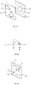
- FIG. 2A It is diagrammatically depicted in figure 2A how touching of the surface 6 comprising the sensors activates the light-emitting portion of the surface 7 situated at the other side of the housing.
- Placing the fingers of a hand for example thumb and index finger, cf. figure 2B ) on two spots A and B located at a short distance from one another indicates the size of the light-emitting portion 8 of the surface 7.
- the diameter of the portion 8 is defined by the distance between A and B on the surface 6.
- the distance between A and B is increased (i.e. the distance between thumb and index finger is increased by the user dragging them over the surface), the light-emitting portion in the surface 7 will increase to a size referenced 9.
- the increase in the distance has been indicated with two arrows up to the points where the distance between A' and B' corresponding to the size 9 is reached.
- the width of the beam of the light emitted by the LEDs is thus adjusted in that the wall surface comprising the sensors is touched with two or more fingers of a hand, the distance between which is changed by the user.
- the width of the beam of the light emitted by the light-emitting elements is coupled to the greatest distance between sensors on the surface touched by the user.
- the beam is not influenced by an increase in the distance between the thumb and one or more fingers, but by a repeated touching of the sensors ("iterative pinching", whereby the diameter of the beam is increased or reduced, for example, in that the sensor surface is repeatedly touched with two fingers on the same starting point at intervals).
- the increase of the light-emitting portion 8 of the surface 7 then is proportional to the increase in the distance A-B or to the speed of that increase, and vice versa.
- the surface 6 is shown on which the intensity of the light emitted by the light-emitting elements is increased or decreased in dependence on a direction of rotation (from C to C' or from D to D', respectively, as indicated by the arrows) by means of a circular movement executed by the fingers of a hand around a virtual point P on the wall surface comprising the sensors.
- the brightness will then be dependent on the value of the angle ⁇ .
- the colour of the emitted light of these RGB LEDs may be set and modified by means of this circular movement.
- the light-emitting elements on the surface 7 are switched off by means of a quick up-and-down touching movement of the hand on or near the wall surface 6. No further switches (such as in the base of the luminaire) are then necessary for this purpose.
- the sensors in the surface 6 are constructed as pressure sensors in an embodiment.
- the intensity or the width of the light beam can now be influenced by briefly pressing somewhat harder with the thumb while the pressure exerted on the sensors by the other fingers of the hand is kept constant. This may also be achieved with the use of proximity sensors.
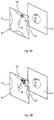
- FIG 3A shows an embodiment of the luminaire according to the invention wherein a user can manually set a certain colour.
- a portion of the wall surface comprising the sensors 6 is coupled to one or more RGB LEDs which each emit light of a certain colour during operation.
- the colour can be integrated with a colour emitted by other elements during their operation in that the hand is dragged over the wall surface comprising the sensors.
- the intensity of the emitted coloured light can also be set during this.
- the touch surface 6 has portions 10, 11, and 12 which act as sources for, for example, three primary colours (RGB).
- RGB three primary colours
- the portion of the surface that is coupled to a portion that emits white light is referenced 13.
- R+, G, and B the contribution of the colour red in the white light can be reduced in that, starting from 13, the finger is moved over the surface in the direction of 14.
- Fig. 3B shows a situation similar to that in figure 3A , but with an added possibility: by increasing the surface area that is touched in the red portion 10 a proportional increase of the red component in the emitted light can be realised. This is indicated by three touch points 15 that are moved in the direction of 16.
- the result in the surface 7 is represented as R++, G, and B.
- the input upon touching of the sensors is stored in a memory.
- a movement over the sensor surface is registered in the memory, for example, at the start and the start location up to the moment and location of release. It is also possible to effect a registration in the memory if the finger or hand is held on the sensor surface for a short period only and is subsequently removed again.
- an activation of the sensors is stored in the memory, for example, in that fingers are moved over a portion of the sensor surface.
- the sensors are activated anew via a program stored in the memory in that a hand is held for some time at a short, detectable distance from the "programmed" sensor surface while making a reciprocating movement. This is denoted "reproducing" in this context.
- Other quantities may also be registered in the memory, such as sensor actions for changing the beam width, the intensity, and/or the colour of the emitted light, and the like.
Landscapes
- Arrangement Of Elements, Cooling, Sealing, Or The Like Of Lighting Devices (AREA)
- Circuit Arrangement For Electric Light Sources In General (AREA)
- Electroluminescent Light Sources (AREA)
Description
- The invention relates to a luminaire in accordance to the preamble of
claim 1. - Luminaires are used both for interior and for outdoor lighting. The known luminaires for interior lighting (such as those for use in a home or an office) are usually provided with (halogen) incandescent lamps or fluorescent lamps arranged in the housing of the luminaire. The lamps are switched on and off by a user by means of a switch provided in or near the house.
- Nowadays, however, various more compact light emitting elements such as light emitting diodes (LEDs) are increasingly used in luminaires because of the high luminous efficacy and long operational life of these light sources. Since these light sources are so compact, luminaires can now be used having shapes and dimensions that were practically impossible with conventional lamps.
- The influencing and control of the light output of lamp systems and luminaires by means of plates or surfaces with sensors sensitive to touch is known, for example, from the published American patent application
US 2002/0159267 . A touch sensor with a brightness control for light sources is described therein for which a tactile plate is used, for example made of glass or synthetic resin. - The light source can be switched on or off in that the plate is touched. In an embodiment, said plate is coupled to an electric circuit by means of which a user can adjust the intensity of the light sources. The intensity of the light can be adjusted as desired by a user with such a plate, which has the function of an electronic panel. Such a plate is situated in a location at some distance from the housing with the light sources. This occupies more space, which may be inconvenient for the user.
- An example of the
preamble claim 1 is for example disclosed inWO2007/072315 . This patent publication discloses a flat interface switching device for controlling light sources including a target region, and an indicator which has to be moved into the target region by a user using a finger. -
US 2005/028299 discloses a light system manager for composing light shows. - There are also elongate luminaires in which LEDs arranged in a row are individually coupled to respective sensors placed behind them such that the LEDs emit light when a user touches the respective sensor with his/her hand. Such a one dimensional arrangement offers the user few possibilities of influencing the beam shape of the emitted light in accordance with his/her own wishes.
- It is an object of the invention to provide a luminaire of which many variables, such as the intensity, the beam width, and the colour of the light emitted during operation, can be adjusted by a user in a simple manner.
- According to the invention, a luminaire for this purpose is characterised in that the sensors are arranged multidimensionally, and the number of activated light-emitting elements is proportional to the size of the wall surface comprising sensors that is touched by the user.
- Given a multidimensional arrangement of the sensors such as, for example, on a two-dimensional sensor surface in the wall of the housing, many possibilities for the output of characteristic shapes of light emitted by the luminaire can be realised upon a touch by a user. In the case of a three-dimensional arrangement of sensors there may be, for example, a curved surface with sensors or a number of surfaces comprising sensors and enclosing angles with one another. The sensors will generally be touched by a user's hand for activation. It is also conceivable, however, that sensors can be influenced not only by actual touching, but also in that a hand is held, for example, at a very close distance above the sensors. This will also be defined as "touching" herein.
- The quantity of light emitted by the luminaire during its operation can be influenced in a very simple, user-friendly, and playful manner in a luminaire according to the invention. It stimulates a user to obtain a personally desired lighting effect by means of a manual action.
- The light-emitting elements accommodated in the wall of the housing are preferably light-emitting diodes (LEDs). Such light sources have a low power consumption and can be incorporated in the wall of the housing in a simple manner on account of their compactness. LEDs also have the advantage that the colour of the emitted light can be adjusted, which is of benefit in certain special applications.
- Preferably, a touching of the wall surface comprising the sensors in multiple directions by a user activates the light-emitting elements in corresponding directions, there being a linear relation between the order in time and space in which the light-emitting elements are activated on the one hand and the speed with which and the locations where the sensors were touched on the other. This embodiment has the advantage that a direct and fast adjustment by a user is possible through touching of the sensors. Among the particular variables that may be influenced are light intensity, colour, beam width, and the dynamism of the emitted light.
- The sensors may be provided in a part of the housing of the luminaire that is located at some distance from the light-emitting elements. Preferably, the wall surface comprising the sensors is situated on that side of the housing that faces away from the light emission side. They will then be accommodated in the wall portion that is located behind the light emission side. Operation by a user will then take place directly on the side of the housing located behind the light sources. A user will thus more readily have the feeling that the emitted light is directly attuned to his/her wishes.
- The invention will now be explained in more detail with reference to a drawing in which the preferred embodiments of the luminaire according to the invention are diagrammatically depicted. The invention, however, is by no means limited to these embodiments. In the drawing:
-
Figure 1 shows a luminaire according to the invention in perspective view; -
Figure 2 diagrammatically shows an embodiment in which the sensor surface is touched by the fingers of a hand; and -
Figure 3 shows, also diagrammatically, an embodiment in which the colour of the emitted light is influenced. - The luminaire of
figure 1 comprises a semitransparentsynthetic resin housing 1 with light-emitting elements (inorganic LEDs) 2 located near alight emission side 3 of the housing. They are activated in that a user touches a group ofsensors 4 which are accommodated in the rear wall of the housing and which are arranged in a matrix over the slightly curved surface thereof. The number of LEDs to be activated by a user is proportional to the size of the wall surface comprising sensors that is touched by the user. The user him/herself makes the desired adjustment, for example by directing a wide beam or a comparatively narrow beam at an object. The housing is provided with abase 5 with which it can be placed, for example, on a table. The sensors are sensitive to touching and are grouped in a multidimensional manner, as are the LEDs. Thelight emission side 3 and theother side 4 of the housing are both slightly curved. The wall surface comprising the sensors is sensitive to touching in several directions, and the light-emitting elements are activated in the corresponding directions. This will be discussed in more detail with reference tofigures 2A to 2C . - It is diagrammatically depicted in
figure 2A how touching of the surface 6 comprising the sensors activates the light-emitting portion of thesurface 7 situated at the other side of the housing. Placing the fingers of a hand (for example thumb and index finger, cf.figure 2B ) on two spots A and B located at a short distance from one another indicates the size of the light-emittingportion 8 of thesurface 7. The diameter of theportion 8 is defined by the distance between A and B on the surface 6. When the distance between A and B is increased (i.e. the distance between thumb and index finger is increased by the user dragging them over the surface), the light-emitting portion in thesurface 7 will increase to a size referenced 9. The increase in the distance has been indicated with two arrows up to the points where the distance between A' and B' corresponding to the size 9 is reached. The width of the beam of the light emitted by the LEDs is thus adjusted in that the wall surface comprising the sensors is touched with two or more fingers of a hand, the distance between which is changed by the user. - The width of the beam of the light emitted by the light-emitting elements is coupled to the greatest distance between sensors on the surface touched by the user.
- In an alternative embodiment, the beam is not influenced by an increase in the distance between the thumb and one or more fingers, but by a repeated touching of the sensors ("iterative pinching", whereby the diameter of the beam is increased or reduced, for example, in that the sensor surface is repeatedly touched with two fingers on the same starting point at intervals). The increase of the light-emitting
portion 8 of thesurface 7 then is proportional to the increase in the distance A-B or to the speed of that increase, and vice versa. - In the embodiment of
figure 2C , the surface 6 is shown on which the intensity of the light emitted by the light-emitting elements is increased or decreased in dependence on a direction of rotation (from C to C' or from D to D', respectively, as indicated by the arrows) by means of a circular movement executed by the fingers of a hand around a virtual point P on the wall surface comprising the sensors. The brightness will then be dependent on the value of the angle α. - In a special embodiment with RGB LEDs, the colour of the emitted light of these RGB LEDs may be set and modified by means of this circular movement.
- In another embodiment, the light-emitting elements on the
surface 7 are switched off by means of a quick up-and-down touching movement of the hand on or near the wall surface 6. No further switches (such as in the base of the luminaire) are then necessary for this purpose. - The sensors in the surface 6 are constructed as pressure sensors in an embodiment. The intensity or the width of the light beam can now be influenced by briefly pressing somewhat harder with the thumb while the pressure exerted on the sensors by the other fingers of the hand is kept constant. This may also be achieved with the use of proximity sensors.
-
Figure 3A shows an embodiment of the luminaire according to the invention wherein a user can manually set a certain colour. A portion of the wall surface comprising the sensors 6 is coupled to one or more RGB LEDs which each emit light of a certain colour during operation. The colour can be integrated with a colour emitted by other elements during their operation in that the hand is dragged over the wall surface comprising the sensors. The intensity of the emitted coloured light can also be set during this. - The touch surface 6 has
portions portion 10, the colour green to 11, and the colour blue to 12. The portion of the surface that is coupled to a portion that emits white light is referenced 13. When a finger performs a movement over the sensor surface from location 14 to location 13 (in the direction of the arrow), more red light can be admixed. This is indicated as R+, G, and B in thesurface 7. Conversely, the contribution of the colour red in the white light can be reduced in that, starting from 13, the finger is moved over the surface in the direction of 14. -
Fig. 3B shows a situation similar to that infigure 3A , but with an added possibility: by increasing the surface area that is touched in the red portion 10 a proportional increase of the red component in the emitted light can be realised. This is indicated by threetouch points 15 that are moved in the direction of 16. The result in thesurface 7 is represented as R++, G, and B. - In a special embodiment, the input upon touching of the sensors is stored in a memory. A movement over the sensor surface is registered in the memory, for example, at the start and the start location up to the moment and location of release. It is also possible to effect a registration in the memory if the finger or hand is held on the sensor surface for a short period only and is subsequently removed again.
- In another embodiment, an activation of the sensors is stored in the memory, for example, in that fingers are moved over a portion of the sensor surface. The sensors are activated anew via a program stored in the memory in that a hand is held for some time at a short, detectable distance from the "programmed" sensor surface while making a reciprocating movement. This is denoted "reproducing" in this context.
- Other quantities may also be registered in the memory, such as sensor actions for changing the beam width, the intensity, and/or the colour of the emitted light, and the like.
Claims (13)
- A luminaire (1) provided with a housing (1) with light emitting elements (2) which are located near a light emission side (3; 7) of the housing (1) and which are activated in that a user touches one or more sensors (4) accommodated in a wall (6) of the housing, wherein the sensors (4) are arranged multidimensionally, characterised in that, the number of activated light emitting elements (2) is proportional to the size of the wall surface (6) comprising sensors (4) that is touched by the user.
- A luminaire according to claim 1, characterised in that a touching of the wall surface (6) comprising the sensors (4) in multiple directions by a user activates the light emitting elements (2) in corresponding directions, there being a linear relation between the order in time and space in which the light emitting elements are activated on the one hand and the speed with which and the locations where the sensors were touched on the other.
- A luminaire according to claim 1 or 2, characterised in that the wall surface (6) comprising the sensors (2) is situated on that side of the housing that faces away from the light emission side (3; 7).
- A luminaire according to claim 1, 2, or 3, characterised in that the width of a beam of the light emitted by the light emitting elements (2) can be adjusted through touching of the wall surface (6) comprising the sensors (4) in two spots (A, B; A', B') located at some distance from one another, which distance can be varied by a user.
- A luminaire according to claim 4, characterised in that the width of a beam of the light emitted by the light emitting elements (2) is coupled to the greatest distance between the sensors (4) on the surface (6) that is touched by a user.
- A luminaire according to claim 1, 2, or 3, characterised in that the beam width, the intensity, and/or the colour of the light emitted by the light emitting elements (2) can be adjusted in that the sensor surface is touched iteratively.
- A luminaire according to any one or more of the preceding claims, characterised in that the intensity of the light emitted by the light emitting elements (2) is increased or decreased by means of a circular touching movement (C, D; C', D') around a virtual point (P) on the wall surface (6) comprising the sensors (4) in dependence on a direction of rotation (α) during said touching movement.
- A luminaire according to any one or more of the preceding claims, characterised in that the sensors (4) in the wall surface (6) are pressure sensors.
- A luminaire according to any one or more of the preceding claims, characterised in that the light emitting elements (2) are switched off by means of a quick up and down movement over the wall surface (6) comprising the sensors (4).
- A luminaire according to any one or more of the preceding claims, characterised in that at least a portion of the wall surface (6) comprising the sensors (4) is coupled to one or more light emitting elements (2) which each emit light of a certain colour (R, G, B) during operation, which colour can be integrated with a colour emitted by other elements during their operation by dragging over the wall surface (6) comprising the sensors (4).
- A luminaire according to claim 10, characterised in that the intensity of the emitted coloured light is adjustable.
- A luminaire according to any one or more of the preceding claims, characterised in that the movement over the surface (6) comprising the sensors (4) can be registered and can be stored in a memory, after which a user can reproduce the quantities stored in the memory.
- A luminaire according to any one or more of the preceding claims, characterised in that the light emitting elements (2) are light emitting diodes (LEDs).
Applications Claiming Priority (2)
| Application Number | Priority Date | Filing Date | Title |
|---|---|---|---|
| NL1035544A NL1035544C2 (en) | 2008-06-05 | 2008-06-05 | Lighting fixture. |
| PCT/NL2009/000113 WO2009148300A1 (en) | 2008-06-05 | 2009-05-13 | Luminaire |
Publications (3)
| Publication Number | Publication Date |
|---|---|
| EP2283702A1 EP2283702A1 (en) | 2011-02-16 |
| EP2283702B1 true EP2283702B1 (en) | 2017-10-11 |
| EP2283702B2 EP2283702B2 (en) | 2021-05-19 |
Family
ID=40260761
Family Applications (1)
| Application Number | Title | Priority Date | Filing Date |
|---|---|---|---|
| EP09758547.5A Not-in-force EP2283702B2 (en) | 2008-06-05 | 2009-05-13 | Luminaire |
Country Status (5)
| Country | Link |
|---|---|
| US (1) | US9713221B2 (en) |
| EP (1) | EP2283702B2 (en) |
| JP (1) | JP2011524608A (en) |
| NL (1) | NL1035544C2 (en) |
| WO (1) | WO2009148300A1 (en) |
Families Citing this family (8)
| Publication number | Priority date | Publication date | Assignee | Title |
|---|---|---|---|---|
| JP6097963B2 (en) * | 2012-09-13 | 2017-03-22 | パナソニックIpマネジメント株式会社 | Lighting system |
| NL2010728C2 (en) * | 2013-04-29 | 2014-10-30 | Aesthetic Interactions B V | Luminaire. |
| WO2014178713A1 (en) | 2013-04-29 | 2014-11-06 | Metatronics B.V. | Luminaire |
| NL2011182C2 (en) * | 2013-07-17 | 2015-01-21 | Aesthetic Interactions B V | Luminaire system. |
| JP6495294B2 (en) * | 2013-09-16 | 2019-04-03 | シグニファイ ホールディング ビー ヴィ | Method and apparatus for controlling illumination |
| ES2641221T3 (en) * | 2013-10-08 | 2017-11-08 | Philips Lighting Holding B.V. | Methods and devices for touch-sensitive lighting control |
| EP2922370B1 (en) * | 2014-03-21 | 2019-09-11 | Osram Sylvania Inc. | Techniques and graphical user interface for controlling solid-state luminaire with electronically adjustable light beam distribution |
| WO2019002012A1 (en) | 2017-06-27 | 2019-01-03 | Philips Lighting Holding B.V. | A device with a touch user interface for controlling a load, a system and a method thereof |
Citations (5)
| Publication number | Priority date | Publication date | Assignee | Title |
|---|---|---|---|---|
| WO2003059016A1 (en) | 2002-01-08 | 2003-07-17 | Royal College Of Art | Illuminating surface |
| US20050248299A1 (en) | 2003-11-20 | 2005-11-10 | Color Kinetics Incorporated | Light system manager |
| JP2006185765A (en) | 2004-12-28 | 2006-07-13 | Yoshiro Mizuno | Lighting system having independent control function, electric decoration system, and display system |
| WO2007072315A1 (en) | 2005-12-22 | 2007-06-28 | Koninklijke Philips Electronics N.V. | User interface and method for control of light systems |
| CN201066056Y (en) | 2007-06-11 | 2008-05-28 | 精碟科技股份有限公司 | Lighting apparatus |
Family Cites Families (10)
| Publication number | Priority date | Publication date | Assignee | Title |
|---|---|---|---|---|
| US2632098A (en) † | 1949-09-14 | 1953-03-17 | Vincent J Marchese | Selectable switching means for stand lamps |
| US4751625A (en) * | 1987-06-26 | 1988-06-14 | Lin John Y | Body-electrostatic induction type of lamp device |
| US20020159267A1 (en) | 1999-12-09 | 2002-10-31 | Shuangqun Zhao | Touch-sensitive switch with brightness-control for lamps |
| JP2006525634A (en) * | 2003-05-07 | 2006-11-09 | コーニンクレッカ フィリップス エレクトロニクス エヌ ヴィ | User interface for controlling light emitting diodes |
| US20050028299A1 (en) | 2003-08-07 | 2005-02-10 | Lg Electronics Inc. | Method for sensing amount of clothes in washing machine |
| US7054133B2 (en) * | 2004-03-22 | 2006-05-30 | Margaret Orth | Electronic textile touch light controller |
| JP2006306305A (en) * | 2005-04-28 | 2006-11-09 | T An T:Kk | Interior light for vehicle |
| FR2892594B1 (en) * | 2005-10-21 | 2007-12-07 | Saint Gobain | LIGHT STRUCTURE COMPRISING AT LEAST ONE ELECTROLUMINESCENT DIODE, ITS MANUFACTURE AND ITS APPLICATIONS |
| CN101379461A (en) * | 2005-12-30 | 2009-03-04 | 苹果公司 | Portable electronic device with multi-touch input |
| EP2070394B8 (en) * | 2006-09-27 | 2019-04-10 | Signify Holding B.V. | Color selection input device and method |
-
2008
- 2008-06-05 NL NL1035544A patent/NL1035544C2/en not_active IP Right Cessation
-
2009
- 2009-05-13 JP JP2011512399A patent/JP2011524608A/en active Pending
- 2009-05-13 US US12/995,878 patent/US9713221B2/en not_active Expired - Fee Related
- 2009-05-13 WO PCT/NL2009/000113 patent/WO2009148300A1/en active Application Filing
- 2009-05-13 EP EP09758547.5A patent/EP2283702B2/en not_active Not-in-force
Patent Citations (5)
| Publication number | Priority date | Publication date | Assignee | Title |
|---|---|---|---|---|
| WO2003059016A1 (en) | 2002-01-08 | 2003-07-17 | Royal College Of Art | Illuminating surface |
| US20050248299A1 (en) | 2003-11-20 | 2005-11-10 | Color Kinetics Incorporated | Light system manager |
| JP2006185765A (en) | 2004-12-28 | 2006-07-13 | Yoshiro Mizuno | Lighting system having independent control function, electric decoration system, and display system |
| WO2007072315A1 (en) | 2005-12-22 | 2007-06-28 | Koninklijke Philips Electronics N.V. | User interface and method for control of light systems |
| CN201066056Y (en) | 2007-06-11 | 2008-05-28 | 精碟科技股份有限公司 | Lighting apparatus |
Non-Patent Citations (1)
| Title |
|---|
| WINDELL OSKAY: "Interactive LED coffee tables", EVILMADSCIENTIST, 20 May 2007 (2007-05-20), XP055512092, Retrieved from the Internet <URL:https://www.evilmadscientist.com/2007/interactive-led-coffee-tables> |
Also Published As
| Publication number | Publication date |
|---|---|
| EP2283702A1 (en) | 2011-02-16 |
| WO2009148300A1 (en) | 2009-12-10 |
| US20110181207A1 (en) | 2011-07-28 |
| EP2283702B2 (en) | 2021-05-19 |
| NL1035544C2 (en) | 2009-12-08 |
| JP2011524608A (en) | 2011-09-01 |
| US9713221B2 (en) | 2017-07-18 |
Similar Documents
| Publication | Publication Date | Title |
|---|---|---|
| EP2283702B1 (en) | Luminaire | |
| EP1745681B1 (en) | Lighting device with user interface for light control | |
| CN109076687B (en) | Gesture-based control device for controlling electrical loads | |
| JP5662440B2 (en) | Lighting fixture with touch pattern control interface | |
| US9220155B2 (en) | Lamp and switch apparatus thereof | |
| CN107110513B (en) | Kitchen furniture set with lighting system | |
| EP2718623B1 (en) | Retrofit lighting device | |
| JP6495294B2 (en) | Method and apparatus for controlling illumination | |
| JP5931285B2 (en) | Lighting fixture with touch-sensitive light emitting surface | |
| JP2013503428A (en) | Lighting fixture and method for controlling a lighting fixture | |
| US9155154B2 (en) | Operating device for driving a multicolored light source and illumination device | |
| CN1499135A (en) | Display of illuminator for household electrical heating device | |
| JP2012186071A (en) | Illumination control system | |
| KR20180087300A (en) | Lighting device and control method thereof | |
| JP2021501443A (en) | Light source sensitive optics with reconfigurable chip-on-board light emitting diode array | |
| JP2004127202A (en) | Computer case | |
| TWM483361U (en) | Lamp with multi-functional device | |
| KR20080040131A (en) | A tact knob structure of the lcd monitor |
Legal Events
| Date | Code | Title | Description |
|---|---|---|---|
| PUAI | Public reference made under article 153(3) epc to a published international application that has entered the european phase |
Free format text: ORIGINAL CODE: 0009012 |
|
| 17P | Request for examination filed |
Effective date: 20101125 |
|
| AK | Designated contracting states |
Kind code of ref document: A1 Designated state(s): AT BE BG CH CY CZ DE DK EE ES FI FR GB GR HR HU IE IS IT LI LT LU LV MC MK MT NL NO PL PT RO SE SI SK TR |
|
| AX | Request for extension of the european patent |
Extension state: AL BA RS |
|
| DAX | Request for extension of the european patent (deleted) | ||
| 17Q | First examination report despatched |
Effective date: 20111121 |
|
| RAP1 | Party data changed (applicant data changed or rights of an application transferred) |
Owner name: AESTHETIC INTERACTIONS B.V. |
|
| 19U | Interruption of proceedings before grant |
Effective date: 20131224 |
|
| 19W | Proceedings resumed before grant after interruption of proceedings |
Effective date: 20140801 |
|
| RAP1 | Party data changed (applicant data changed or rights of an application transferred) |
Owner name: METATRONICS B.V. |
|
| RAP1 | Party data changed (applicant data changed or rights of an application transferred) |
Owner name: KONINKLIJKE PHILIPS N.V. |
|
| RAP1 | Party data changed (applicant data changed or rights of an application transferred) |
Owner name: PHILIPS LIGHTING HOLDING B.V. |
|
| GRAP | Despatch of communication of intention to grant a patent |
Free format text: ORIGINAL CODE: EPIDOSNIGR1 |
|
| STAA | Information on the status of an ep patent application or granted ep patent |
Free format text: STATUS: GRANT OF PATENT IS INTENDED |
|
| INTG | Intention to grant announced |
Effective date: 20170508 |
|
| GRAS | Grant fee paid |
Free format text: ORIGINAL CODE: EPIDOSNIGR3 |
|
| GRAA | (expected) grant |
Free format text: ORIGINAL CODE: 0009210 |
|
| STAA | Information on the status of an ep patent application or granted ep patent |
Free format text: STATUS: THE PATENT HAS BEEN GRANTED |
|
| AK | Designated contracting states |
Kind code of ref document: B1 Designated state(s): AT BE BG CH CY CZ DE DK EE ES FI FR GB GR HR HU IE IS IT LI LT LU LV MC MK MT NL NO PL PT RO SE SI SK TR |
|
| REG | Reference to a national code |
Ref country code: GB Ref legal event code: FG4D |
|
| REG | Reference to a national code |
Ref country code: CH Ref legal event code: EP |
|
| REG | Reference to a national code |
Ref country code: IE Ref legal event code: FG4D |
|
| REG | Reference to a national code |
Ref country code: AT Ref legal event code: REF Ref document number: 937104 Country of ref document: AT Kind code of ref document: T Effective date: 20171115 |
|
| REG | Reference to a national code |
Ref country code: DE Ref legal event code: R096 Ref document number: 602009048808 Country of ref document: DE |
|
| REG | Reference to a national code |
Ref country code: NL Ref legal event code: MP Effective date: 20171011 |
|
| REG | Reference to a national code |
Ref country code: LT Ref legal event code: MG4D |
|
| REG | Reference to a national code |
Ref country code: AT Ref legal event code: MK05 Ref document number: 937104 Country of ref document: AT Kind code of ref document: T Effective date: 20171011 |
|
| PG25 | Lapsed in a contracting state [announced via postgrant information from national office to epo] |
Ref country code: NL Free format text: LAPSE BECAUSE OF FAILURE TO SUBMIT A TRANSLATION OF THE DESCRIPTION OR TO PAY THE FEE WITHIN THE PRESCRIBED TIME-LIMIT Effective date: 20171011 |
|
| PG25 | Lapsed in a contracting state [announced via postgrant information from national office to epo] |
Ref country code: SE Free format text: LAPSE BECAUSE OF FAILURE TO SUBMIT A TRANSLATION OF THE DESCRIPTION OR TO PAY THE FEE WITHIN THE PRESCRIBED TIME-LIMIT Effective date: 20171011 Ref country code: NO Free format text: LAPSE BECAUSE OF FAILURE TO SUBMIT A TRANSLATION OF THE DESCRIPTION OR TO PAY THE FEE WITHIN THE PRESCRIBED TIME-LIMIT Effective date: 20180111 Ref country code: FI Free format text: LAPSE BECAUSE OF FAILURE TO SUBMIT A TRANSLATION OF THE DESCRIPTION OR TO PAY THE FEE WITHIN THE PRESCRIBED TIME-LIMIT Effective date: 20171011 Ref country code: LT Free format text: LAPSE BECAUSE OF FAILURE TO SUBMIT A TRANSLATION OF THE DESCRIPTION OR TO PAY THE FEE WITHIN THE PRESCRIBED TIME-LIMIT Effective date: 20171011 Ref country code: ES Free format text: LAPSE BECAUSE OF FAILURE TO SUBMIT A TRANSLATION OF THE DESCRIPTION OR TO PAY THE FEE WITHIN THE PRESCRIBED TIME-LIMIT Effective date: 20171011 |
|
| PG25 | Lapsed in a contracting state [announced via postgrant information from national office to epo] |
Ref country code: BG Free format text: LAPSE BECAUSE OF FAILURE TO SUBMIT A TRANSLATION OF THE DESCRIPTION OR TO PAY THE FEE WITHIN THE PRESCRIBED TIME-LIMIT Effective date: 20180111 Ref country code: GR Free format text: LAPSE BECAUSE OF FAILURE TO SUBMIT A TRANSLATION OF THE DESCRIPTION OR TO PAY THE FEE WITHIN THE PRESCRIBED TIME-LIMIT Effective date: 20180112 Ref country code: AT Free format text: LAPSE BECAUSE OF FAILURE TO SUBMIT A TRANSLATION OF THE DESCRIPTION OR TO PAY THE FEE WITHIN THE PRESCRIBED TIME-LIMIT Effective date: 20171011 Ref country code: IS Free format text: LAPSE BECAUSE OF FAILURE TO SUBMIT A TRANSLATION OF THE DESCRIPTION OR TO PAY THE FEE WITHIN THE PRESCRIBED TIME-LIMIT Effective date: 20180211 Ref country code: LV Free format text: LAPSE BECAUSE OF FAILURE TO SUBMIT A TRANSLATION OF THE DESCRIPTION OR TO PAY THE FEE WITHIN THE PRESCRIBED TIME-LIMIT Effective date: 20171011 Ref country code: HR Free format text: LAPSE BECAUSE OF FAILURE TO SUBMIT A TRANSLATION OF THE DESCRIPTION OR TO PAY THE FEE WITHIN THE PRESCRIBED TIME-LIMIT Effective date: 20171011 |
|
| REG | Reference to a national code |
Ref country code: DE Ref legal event code: R026 Ref document number: 602009048808 Country of ref document: DE |
|
| PLBI | Opposition filed |
Free format text: ORIGINAL CODE: 0009260 |
|
| PLAX | Notice of opposition and request to file observation + time limit sent |
Free format text: ORIGINAL CODE: EPIDOSNOBS2 |
|
| PG25 | Lapsed in a contracting state [announced via postgrant information from national office to epo] |
Ref country code: CZ Free format text: LAPSE BECAUSE OF FAILURE TO SUBMIT A TRANSLATION OF THE DESCRIPTION OR TO PAY THE FEE WITHIN THE PRESCRIBED TIME-LIMIT Effective date: 20171011 Ref country code: SK Free format text: LAPSE BECAUSE OF FAILURE TO SUBMIT A TRANSLATION OF THE DESCRIPTION OR TO PAY THE FEE WITHIN THE PRESCRIBED TIME-LIMIT Effective date: 20171011 Ref country code: DK Free format text: LAPSE BECAUSE OF FAILURE TO SUBMIT A TRANSLATION OF THE DESCRIPTION OR TO PAY THE FEE WITHIN THE PRESCRIBED TIME-LIMIT Effective date: 20171011 Ref country code: EE Free format text: LAPSE BECAUSE OF FAILURE TO SUBMIT A TRANSLATION OF THE DESCRIPTION OR TO PAY THE FEE WITHIN THE PRESCRIBED TIME-LIMIT Effective date: 20171011 |
|
| 26 | Opposition filed |
Opponent name: MOLNIA, DAVID Effective date: 20180711 |
|
| PG25 | Lapsed in a contracting state [announced via postgrant information from national office to epo] |
Ref country code: RO Free format text: LAPSE BECAUSE OF FAILURE TO SUBMIT A TRANSLATION OF THE DESCRIPTION OR TO PAY THE FEE WITHIN THE PRESCRIBED TIME-LIMIT Effective date: 20171011 Ref country code: PL Free format text: LAPSE BECAUSE OF FAILURE TO SUBMIT A TRANSLATION OF THE DESCRIPTION OR TO PAY THE FEE WITHIN THE PRESCRIBED TIME-LIMIT Effective date: 20171011 |
|
| PLBB | Reply of patent proprietor to notice(s) of opposition received |
Free format text: ORIGINAL CODE: EPIDOSNOBS3 |
|
| PG25 | Lapsed in a contracting state [announced via postgrant information from national office to epo] |
Ref country code: SI Free format text: LAPSE BECAUSE OF FAILURE TO SUBMIT A TRANSLATION OF THE DESCRIPTION OR TO PAY THE FEE WITHIN THE PRESCRIBED TIME-LIMIT Effective date: 20171011 |
|
| RAP2 | Party data changed (patent owner data changed or rights of a patent transferred) |
Owner name: PHILIPS LIGHTING HOLDING B.V. |
|
| REG | Reference to a national code |
Ref country code: CH Ref legal event code: PL |
|
| REG | Reference to a national code |
Ref country code: BE Ref legal event code: MM Effective date: 20180531 |
|
| PG25 | Lapsed in a contracting state [announced via postgrant information from national office to epo] |
Ref country code: MC Free format text: LAPSE BECAUSE OF FAILURE TO SUBMIT A TRANSLATION OF THE DESCRIPTION OR TO PAY THE FEE WITHIN THE PRESCRIBED TIME-LIMIT Effective date: 20171011 |
|
| REG | Reference to a national code |
Ref country code: IE Ref legal event code: MM4A |
|
| PG25 | Lapsed in a contracting state [announced via postgrant information from national office to epo] |
Ref country code: CH Free format text: LAPSE BECAUSE OF NON-PAYMENT OF DUE FEES Effective date: 20180531 Ref country code: LI Free format text: LAPSE BECAUSE OF NON-PAYMENT OF DUE FEES Effective date: 20180531 |
|
| RAP2 | Party data changed (patent owner data changed or rights of a patent transferred) |
Owner name: SIGNIFY HOLDING B.V. |
|
| PG25 | Lapsed in a contracting state [announced via postgrant information from national office to epo] |
Ref country code: LU Free format text: LAPSE BECAUSE OF NON-PAYMENT OF DUE FEES Effective date: 20180513 |
|
| PG25 | Lapsed in a contracting state [announced via postgrant information from national office to epo] |
Ref country code: FR Free format text: LAPSE BECAUSE OF NON-PAYMENT OF DUE FEES Effective date: 20180531 Ref country code: IE Free format text: LAPSE BECAUSE OF NON-PAYMENT OF DUE FEES Effective date: 20180513 |
|
| PG25 | Lapsed in a contracting state [announced via postgrant information from national office to epo] |
Ref country code: BE Free format text: LAPSE BECAUSE OF NON-PAYMENT OF DUE FEES Effective date: 20180531 |
|
| REG | Reference to a national code |
Ref country code: DE Ref legal event code: R079 Ref document number: 602009048808 Country of ref document: DE Free format text: PREVIOUS MAIN CLASS: H05B0033080000 Ipc: H05B0045000000 |
|
| PG25 | Lapsed in a contracting state [announced via postgrant information from national office to epo] |
Ref country code: MT Free format text: LAPSE BECAUSE OF NON-PAYMENT OF DUE FEES Effective date: 20180513 |
|
| PG25 | Lapsed in a contracting state [announced via postgrant information from national office to epo] |
Ref country code: TR Free format text: LAPSE BECAUSE OF FAILURE TO SUBMIT A TRANSLATION OF THE DESCRIPTION OR TO PAY THE FEE WITHIN THE PRESCRIBED TIME-LIMIT Effective date: 20171011 |
|
| PG25 | Lapsed in a contracting state [announced via postgrant information from national office to epo] |
Ref country code: HU Free format text: LAPSE BECAUSE OF FAILURE TO SUBMIT A TRANSLATION OF THE DESCRIPTION OR TO PAY THE FEE WITHIN THE PRESCRIBED TIME-LIMIT; INVALID AB INITIO Effective date: 20090513 Ref country code: PT Free format text: LAPSE BECAUSE OF FAILURE TO SUBMIT A TRANSLATION OF THE DESCRIPTION OR TO PAY THE FEE WITHIN THE PRESCRIBED TIME-LIMIT Effective date: 20171011 |
|
| PG25 | Lapsed in a contracting state [announced via postgrant information from national office to epo] |
Ref country code: CY Free format text: LAPSE BECAUSE OF FAILURE TO SUBMIT A TRANSLATION OF THE DESCRIPTION OR TO PAY THE FEE WITHIN THE PRESCRIBED TIME-LIMIT Effective date: 20171011 Ref country code: MK Free format text: LAPSE BECAUSE OF NON-PAYMENT OF DUE FEES Effective date: 20171011 |
|
| REG | Reference to a national code |
Ref country code: DE Ref legal event code: R081 Ref document number: 602009048808 Country of ref document: DE Owner name: SIGNIFY HOLDING B.V., NL Free format text: FORMER OWNER: PHILIPS LIGHTING HOLDING B.V., EINDHOVEN, NL |
|
| PUAH | Patent maintained in amended form |
Free format text: ORIGINAL CODE: 0009272 |
|
| STAA | Information on the status of an ep patent application or granted ep patent |
Free format text: STATUS: PATENT MAINTAINED AS AMENDED |
|
| 27A | Patent maintained in amended form |
Effective date: 20210519 |
|
| AK | Designated contracting states |
Kind code of ref document: B2 Designated state(s): AT BE BG CH CY CZ DE DK EE ES FI FR GB GR HR HU IE IS IT LI LT LU LV MC MK MT NL NO PL PT RO SE SI SK TR |
|
| REG | Reference to a national code |
Ref country code: DE Ref legal event code: R102 Ref document number: 602009048808 Country of ref document: DE |
|
| PGFP | Annual fee paid to national office [announced via postgrant information from national office to epo] |
Ref country code: IT Payment date: 20220519 Year of fee payment: 14 Ref country code: GB Payment date: 20220524 Year of fee payment: 14 |
|
| PGFP | Annual fee paid to national office [announced via postgrant information from national office to epo] |
Ref country code: DE Payment date: 20220628 Year of fee payment: 14 |
|
| REG | Reference to a national code |
Ref country code: DE Ref legal event code: R119 Ref document number: 602009048808 Country of ref document: DE |
|
| GBPC | Gb: european patent ceased through non-payment of renewal fee |
Effective date: 20230513 |
|
| PG25 | Lapsed in a contracting state [announced via postgrant information from national office to epo] |
Ref country code: IT Free format text: LAPSE BECAUSE OF NON-PAYMENT OF DUE FEES Effective date: 20230513 Ref country code: DE Free format text: LAPSE BECAUSE OF NON-PAYMENT OF DUE FEES Effective date: 20231201 Ref country code: GB Free format text: LAPSE BECAUSE OF NON-PAYMENT OF DUE FEES Effective date: 20230513 |