EP2282883B1 - Injection mold friction puller - Google Patents
Injection mold friction puller Download PDFInfo
- Publication number
- EP2282883B1 EP2282883B1 EP09735644A EP09735644A EP2282883B1 EP 2282883 B1 EP2282883 B1 EP 2282883B1 EP 09735644 A EP09735644 A EP 09735644A EP 09735644 A EP09735644 A EP 09735644A EP 2282883 B1 EP2282883 B1 EP 2282883B1
- Authority
- EP
- European Patent Office
- Prior art keywords
- bolt
- jacket
- plate
- friction
- friction puller
- Prior art date
- Legal status (The legal status is an assumption and is not a legal conclusion. Google has not performed a legal analysis and makes no representation as to the accuracy of the status listed.)
- Active
Links
Images





Classifications
-
- B—PERFORMING OPERATIONS; TRANSPORTING
- B29—WORKING OF PLASTICS; WORKING OF SUBSTANCES IN A PLASTIC STATE IN GENERAL
- B29C—SHAPING OR JOINING OF PLASTICS; SHAPING OF MATERIAL IN A PLASTIC STATE, NOT OTHERWISE PROVIDED FOR; AFTER-TREATMENT OF THE SHAPED PRODUCTS, e.g. REPAIRING
- B29C45/00—Injection moulding, i.e. forcing the required volume of moulding material through a nozzle into a closed mould; Apparatus therefor
- B29C45/17—Component parts, details or accessories; Auxiliary operations
- B29C45/26—Moulds
- B29C45/2602—Mould construction elements
-
- B—PERFORMING OPERATIONS; TRANSPORTING
- B29—WORKING OF PLASTICS; WORKING OF SUBSTANCES IN A PLASTIC STATE IN GENERAL
- B29C—SHAPING OR JOINING OF PLASTICS; SHAPING OF MATERIAL IN A PLASTIC STATE, NOT OTHERWISE PROVIDED FOR; AFTER-TREATMENT OF THE SHAPED PRODUCTS, e.g. REPAIRING
- B29C45/00—Injection moulding, i.e. forcing the required volume of moulding material through a nozzle into a closed mould; Apparatus therefor
- B29C45/17—Component parts, details or accessories; Auxiliary operations
- B29C45/26—Moulds
- B29C45/2602—Mould construction elements
- B29C2045/2604—Latching means for successive opening or closing of mould plates
-
- Y—GENERAL TAGGING OF NEW TECHNOLOGICAL DEVELOPMENTS; GENERAL TAGGING OF CROSS-SECTIONAL TECHNOLOGIES SPANNING OVER SEVERAL SECTIONS OF THE IPC; TECHNICAL SUBJECTS COVERED BY FORMER USPC CROSS-REFERENCE ART COLLECTIONS [XRACs] AND DIGESTS
- Y10—TECHNICAL SUBJECTS COVERED BY FORMER USPC
- Y10S—TECHNICAL SUBJECTS COVERED BY FORMER USPC CROSS-REFERENCE ART COLLECTIONS [XRACs] AND DIGESTS
- Y10S425/00—Plastic article or earthenware shaping or treating: apparatus
- Y10S425/812—Venting
Definitions
- the present invention relates to injection molding devices, and more specifically to a friction puller of a multiple plate injection mold.
- Friction pullers are used in injection mold application to help control the sequential movements of various plates during mold operations.
- One such friction puller is shown in German Patent No. DE 2815698 , which is assigned to the HASCO Company.
- Friction pullers made according HASCO have a bolt which has a substantially conical shaped shank. The bolt is inserted into a resin jacket that has a corresponding substantially conical shaped passage for receiving the bolt shank. When the bolt is tightened, the bolt head compresses the jacket lengthwise and the shank presses laterally on the jacket. The result is that under the load from the tightened bolt, the jacket has an increased diameter compared to when it is in an unloaded condition.
- a further type of friction puller is shown in DE 203 02 936 U1 .
- This friction puller has a ductile part and a bearing part.
- the bearing part has a cylindrical seat which is part of a supporting piece.
- the supporting piece has a bore with a thread.
- the supporting piece has a clamping section which supports a deformable jacket. By means of a screw the diameter of the deformable jacket could be varied.
- a bolt with a straight set of threads is used.
- the bolt is secured into a key member that passes through one of the mold plates.
- the key has at least one flat surface to prevent the key from rotating inside the mold plate.
- the end of the key that receives that bolt has a hemispherical wedge section integral to or fixed to the key member.
- a resin jacket is again used.
- the jacket has a hemispherical cup inside one end of the jacket to correspond to the hemispherical wedge on the key member.
- the other end of the jacket has a second hemispherical cup for receiving a hemispherical washer used between the bolt head and the jacket.
- a problem encountered with both of these types of friction pullers is that they do not accommodate typical manufacturing conditions with respect to installation or operational environments, which results in inconsistent performance.
- these products are fix mounted into the mold plates. Thermal expansion, build tolerances and the like can lead to the pullers not being centered with respect to the respective pockets in the opposing mold plates. While small, these misalignments can cause the mold to lock because of different force levels exerted by each of the friction pullers in the mold.
- multiple friction pullers are used in a single mold.
- the present invention is a friction puller for an injection mold.
- the friction puller has a bolt, the bolt has a head portion and a threaded portion.
- the friction puller also has a first substantially hemispherical wedge.
- the first substantially hemispherical wedge has a first passage running through it for the bolt.
- the first passage allows the first substantially hemispherical wedge a first predetermined amount of lateral float relative to the bolt.
- the friction puller has only one substantially hemispherical wedge.
- the friction puller also has a second substantially hemispherical wedge.
- the second substantially hemispherical wedge has a second passage running through it for the bolt.
- the second passage allows the second substantially hemispherical wedge a second predetermined amount of lateral float relative to the bolt.
- the friction puller also has a deformable jacket.
- the jacket has a third passage running through it for the bolt.
- the jacket has only a first substantially hemispherical cup for receiving the one substantially hemispherical wedge.
- the jacket has a first substantially hemispherical cup for receiving the first substantially hemispherical wedge and a second substantially hemispherical cup for receiving the second substantially hemispherical wedge.
- the first hemispherical wedge has a least one vent relief notch disposed in a top surface of the first hemispherical wedge.
- the vent relief notch allows air to pass through during mold operation.
- the deformable jacket preferably has at least one jacket vent notch disposed in a top surface of the deformable jacket. The jacket vent notch also allows air to pass through during mold operation.
- the head portion of the bolt has at least one bolt alignment indicator mark in it.
- the deformable jacket has at least one jacket alignment indicator mark on it.
- the threads on the threaded portion of the bolt have a variable pitch diameter.
- X plate In a typical three-plate injection molding machine, as the name implies, there are three plates involved in the molding operation. Typically these plates are referred to as the X plate, the B plate, and the A plate. A mold pattern is formed between a portion of the B plate and the A plate. A runner pattern is formed on the A plate which faces the X plate.
- the B plate is bolted to a support plate. The support plate is further secured to an ejector box or housing. The ejector box is clamped to a movable platen of the molding machine.
- the X plate is bolted to a top clamp plate, usually with two or more shoulder bolts. The top clamp plate is fixed to the opposing platen of the injection molding machine.
- the mold and runner patterns are filled with heated plastic injected from a reservoir connected to the top clamp plate.
- the moving platen pulls the ejector box and the associated support plate and B plate away from the A plate, thus initiating the sequential opening of the mold plates and the eventual removal of the molded parts and runner.
- the B plate and associated support plate are pulled away.
- At least one friction puller is secured to the B plate.
- the deformable jacket of the friction puller engages, via an interference fit, with a pocket in the A plate.
- the friction puller holds the A plate and the B plate together as the mold clamping force is removed.
- Springs between the A plate and the X plate begin to expand and separate the A plate and X plate at a first parting line.
- the runner breaks free from the A plate and remains attached to the sucker pins.
- Sucker pins are pins secured to the top plate and pass through an opening in the X plate. The sucker pins serve to hold the runner in place while the A plate, B plate, and the support plate are moved away from the X plate. Further movement of the X plate away from the top clamp plate causes the runner to be stripped from the sucker pins.
- the shoulder bolts When the shoulder bolts reach the end of their travel, the shoulder bolts hold the A plate in position and the B plate is moved further away. The A plate and the B plate separate at a second parting line.
- the present invention is a friction puller 100 for an injection mold.
- FIG. 1 shows an exploded front view of a friction puller according to the present invention.
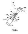
- FIG. 2 and FIG. 2A each shows an exploded perspective view of a friction puller, each according to a different embodiment of the present invention.
- FIG. 3 shows an assembled perspective view of a friction puller according to the present invention.
- the friction puller 100 has a bolt 110, and the bolt 110 has a head portion 105 and a threaded portion 120.
- the friction puller 100 also has a first substantially hemispherical wedge 130.
- the first substantially hemispherical wedge 130 has a first passage 150 running through it for the bolt 110.
- the first passage 150 allows the first substantially hemispherical wedge 130 a first predetermined amount of lateral float relative to the bolt 110. That is, the diameter of the first passage 150 is larger than the diameter of the threaded portion 120 of the bolt 110.
- the first substantially hemispherical wedge 130 has about 0,254 mm of lateral float. This allows the friction puller 100 to self-align, or self-center itself during use. Additionally, this allows for thermal expansion differences between the mold plates.
- the friction puller 100 has only one substantially hemispherical wedge 130.
- the only one substantially hemispherical wedge 130 can be in a position such as shown in FIG. 1 B and FIG. 2A , or can be positioned at an opposite end of a deformable jacket 160.
- the friction puller 100 also has a second substantially hemispherical wedge 210, such as shown in FIGS. 1 and 2 .
- the second substantially hemispherical wedge 210 has a second passage 220 running through it for or to accommodate the bolt 110.
- the second passage 220 allows the second substantially hemispherical wedge 210 a second predetermined amount of lateral float relative to the bolt 110.
- the second substantially hemispherical wedge 210 has about 0,254 mm of lateral float. This allows the friction puller 100 to self-align, or self-center itself during use. Additionally, this allows for thermal expansion differences between the mold plates.
- the friction puller 100 also has the deformable jacket 160.
- the jacket 160 has a third passage 190 running through it for or to accommodate the bolt 110.
- the jacket 160 has a first substantially hemispherical cup 180 for receiving the first substantially hemispherical wedge 130 and a second substantially hemispherical cup 200 for receiving the second substantially hemispherical wedge 210.
- the jacket 160 preferably includes a step in outer diameter, as can be seen in FIG. 1 . The step in outer diameter further enables lateral float of the jacket 160.
- the first hemispherical wedge 130 has a least one vent relief notch 140 disposed in a top surface of the first hemispherical wedge 130.
- the vent relief notch 140 allows air pass through or by the first hemispherical wedge 130 during mold operation.
- the deformable jacket 160 preferably has at least one jacket vent notch 170 disposed in a top surface of the deformable jacket 160.
- the jacket vent notch 170 also allows air to pass through or by deformable jacket 160 during mold operation.
- the head portion 105 of the bolt 110 has at least one bolt alignment indicator mark 250 in it or on a corresponding surface.
- the deformable jacket 160 has at least one jacket alignment indicator mark 260 on it or on a corresponding surface.
- the alignment indicator marks 250 and 260 allow the mold engineer and mold builder to see, and hopefully record, how many turns or rotations of the bolt 110, such as relative to the deformable jacket 160, have been made during installation or maintenance of the mold. For example, each bolt 110 could be turned or rotated the same number of revolutions to achieve the same friction force. Additionally, any adjustments made to the bolt, e.g., a fraction of a turn, could also be seen and recorded.
- the bolt alignment indicator mark 250 is an arrow or other similar mark or structure disposed on a top surface of the head portion 105 of the bolt 110 and the jacket alignment indicator mark 260 comprises an arrow or other similar mark or structure disposed on a top surface of the deformable jacket 160. Any suitable number of alignment marks 250 and 260 can be used. In various preferred embodiments, there are four jacket alignment indicator mark comprises 260.
- FIG. 1A shows a close up front view of the bolt threads of a friction puller 100 according to the present invention.
- the threads on the threaded portion 120 of the bolt 110 have a variable pitch diameter. That is, the threaded portion 120 of the bolt 110 has a first pitch diameter at a first section 125 of the threaded portion 120 and a second pitch diameter at a second section 127 of the threaded portion 120.
- the first pitch diameter can be different from the second pitch diameter.
- variable pitch diameter is different from other fasteners.
- a fastener is engineered to stretch when the fastener head is limited from travel. The stretching is what creates the tightening torque.
- the bolt 110 of the present invention resembles a typical fastener installation, the bolt head 105 is never mating to a solid that limits its travel and produces the tightening torque.
- the variable pitch diameter resists unintentional rotational movement or backing out of the bolt 110 during operation. Furthermore, when the bolt 110 is unscrewed a specified amount for mold maintenance or other reasons the bolt 110 will hold its position without any force being exerted on it from the jacket 160.
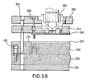
- FIGS. 5A-5C show a three plate mold having a friction puller according to the present invention installed therein going through an opening sequence.
- a typical three-plate injection molding machine there are three plates involved in the molding operation. Typically these plates are referred to as the X plate 310, the B plate 320, and the A plate 330.
- a mold pattern 370 is formed between a portion of the B plate 320 and the A plate 330.
- a runner pattern 335 is formed on the A plate 330 which faces the X plate 310.
- the B plate 320 is bolted to a support plate 350.
- the support plate 350 is further secured to an ejector box or housing (not shown).
- the ejector box is clamped to a movable platen of the molding machine.
- the X plate 310 is bolted to a top clamp plate 360, usually with two or more shoulder bolts 345.
- the top clamp plate 360 is fixed to the opposing platen of the injection molding machine.
- FIG. 5A shows the mold in a closed position.
- the mold 370 and runner patterns 335 are filled with heated plastic injected from a reservoir 380 connected to the top clamp plate.
- the moving platen pulls the ejector box and the associated support plate 350 and B plate 320 away from the A plate 330, thus initiating the sequential opening of the mold plates and the eventual removal of the molded parts and runner 340.
- At least one friction puller 100 is secured to the B plate 320.
- the deformable jacket 160 of the friction puller 100 engages, via an interference fit, a pocket 325 in the A plate 330.
- the friction puller 100 holds the A plate 330 and the B plate together as the mold clamping force is removed.
- Springs between the A plate 330 and the X plate 310 begin to expand and separate the A plate 330 and X plate 310 at a first parting line.
- the runner 340 breaks free from the A plate 330 and remains attached to the sucker pins 390.
- Sucker pins 390 are pins secured to the top plate 360 and pass through an opening in the X plate 310.
- the sucker pins 390 serve to hold the runner 340 in place while the A plate 330, B plate 320, and the support plate 350 are moved away from the X plate 310. Further movement of the X plate 310 away from the top clamp plate 360 causes the runner 340 to be stripped from the sucker pins 390.
- the shoulder bolts 345 When the shoulder bolts 345 reach the end of their travel, shown in FIG. 5C , the shoulder bolts 345 hold the A plate 330 in position and the B plate 320 is moved further away. The A plate 330 and the B plate 320 separate at a second parting line.
Landscapes
- Engineering & Computer Science (AREA)
- Manufacturing & Machinery (AREA)
- Mechanical Engineering (AREA)
- Moulds For Moulding Plastics Or The Like (AREA)
- Injection Moulding Of Plastics Or The Like (AREA)
Description
- The present invention relates to injection molding devices, and more specifically to a friction puller of a multiple plate injection mold.
- Friction pullers are used in injection mold application to help control the sequential movements of various plates during mold operations. One such friction puller is shown in German Patent No.
DE 2815698 , which is assigned to the HASCO Company. Friction pullers made according HASCO have a bolt which has a substantially conical shaped shank. The bolt is inserted into a resin jacket that has a corresponding substantially conical shaped passage for receiving the bolt shank. When the bolt is tightened, the bolt head compresses the jacket lengthwise and the shank presses laterally on the jacket. The result is that under the load from the tightened bolt, the jacket has an increased diameter compared to when it is in an unloaded condition. - A further type of friction puller is shown in
DE 203 02 936 U1 . This friction puller has a ductile part and a bearing part. The bearing part has a cylindrical seat which is part of a supporting piece. The supporting piece has a bore with a thread. Further, the supporting piece has a clamping section which supports a deformable jacket. By means of a screw the diameter of the deformable jacket could be varied. - Another type of friction puller is also produced by HASCO. In these friction pullers, a bolt with a straight set of threads is used. The bolt is secured into a key member that passes through one of the mold plates. The key has at least one flat surface to prevent the key from rotating inside the mold plate. The end of the key that receives that bolt has a hemispherical wedge section integral to or fixed to the key member. A resin jacket is again used. The jacket has a hemispherical cup inside one end of the jacket to correspond to the hemispherical wedge on the key member. The other end of the jacket has a second hemispherical cup for receiving a hemispherical washer used between the bolt head and the jacket. Again, when the bolt is tightened, the hemispherical washer and hemispherical wedge compress the jacket lengthwise forcing the jacket to increase slightly in diameter.
- A problem encountered with both of these types of friction pullers is that they do not accommodate typical manufacturing conditions with respect to installation or operational environments, which results in inconsistent performance. For example, these products are fix mounted into the mold plates. Thermal expansion, build tolerances and the like can lead to the pullers not being centered with respect to the respective pockets in the opposing mold plates. While small, these misalignments can cause the mold to lock because of different force levels exerted by each of the friction pullers in the mold. Typically, multiple friction pullers are used in a single mold.
- Another problem encountered with both of the types of friction pullers described above is the creation of air pressure differentials during use. As the pullers are designed to friction fit into the pockets that receive them, often the puller creates an air tight seal against the pocket. During mold close, the mold has to compress the air in the pocket to close the mold. This compressed air wants to push the puller out of the pocket. Alternatively, if the air escapes-the pocket during mold closure, but the jacket creates an air tight seal once the mold is fully closed, a vacuum is created in the pocket when the puller attempts to pull out from the pocket. Neither of the friction pullers described above provide for air to flow in and out of the pocket during mold open an mold closure operations. Accordingly, either the compressed air or vacuum conditions can occur randomly, creating an undesirable variation in the force exerted by the friction pullers.
- Thus, there remains a need for an improved friction puller. There remains a need for a self-aligning friction puller. There remains a need for a friction puller to controllably allow air to pass into and out of the pocket that receives the friction puller.
- In view of the deficiencies described above, it is an object of the present invention to provide an improved friction puller.
- It is a further object of the present invention to provide a friction puller that is self-aligning.
- It is a further object of the present invention to provide a friction puller that controllably allows air to pass into and out of the pocket that receives the friction puller.
- The present invention is a friction puller for an injection mold. The friction puller has a bolt, the bolt has a head portion and a threaded portion. The friction puller also has a first substantially hemispherical wedge. The first substantially hemispherical wedge has a first passage running through it for the bolt. The first passage allows the first substantially hemispherical wedge a first predetermined amount of lateral float relative to the bolt. In some embodiments of the present invention, the friction puller has only one substantially hemispherical wedge. In other embodiments according to the present invention, the friction puller also has a second substantially hemispherical wedge. The second substantially hemispherical wedge has a second passage running through it for the bolt. The second passage allows the second substantially hemispherical wedge a second predetermined amount of lateral float relative to the bolt.
- The friction puller also has a deformable jacket. The jacket has a third passage running through it for the bolt. In some embodiments of the present invention, the jacket has only a first substantially hemispherical cup for receiving the one substantially hemispherical wedge. In other embodiments according to the present invention, the jacket has a first substantially hemispherical cup for receiving the first substantially hemispherical wedge and a second substantially hemispherical cup for receiving the second substantially hemispherical wedge.
- Preferably, the first hemispherical wedge has a least one vent relief notch disposed in a top surface of the first hemispherical wedge. The vent relief notch allows air to pass through during mold operation. Likewise the deformable jacket preferably has at least one jacket vent notch disposed in a top surface of the deformable jacket. The jacket vent notch also allows air to pass through during mold operation.
- Preferably, the head portion of the bolt has at least one bolt alignment indicator mark in it. Likewise, the deformable jacket has at least one jacket alignment indicator mark on it.
- Preferably, the threads on the threaded portion of the bolt have a variable pitch diameter.
- In a typical three-plate injection molding machine, as the name implies, there are three plates involved in the molding operation. Typically these plates are referred to as the X plate, the B plate, and the A plate. A mold pattern is formed between a portion of the B plate and the A plate. A runner pattern is formed on the A plate which faces the X plate. The B plate is bolted to a support plate. The support plate is further secured to an ejector box or housing. The ejector box is clamped to a movable platen of the molding machine. The X plate is bolted to a top clamp plate, usually with two or more shoulder bolts. The top clamp plate is fixed to the opposing platen of the injection molding machine.
- During the molding operation, the mold and runner patterns are filled with heated plastic injected from a reservoir connected to the top clamp plate. When the plastic has cooled, the moving platen pulls the ejector box and the associated support plate and B plate away from the A plate, thus initiating the sequential opening of the mold plates and the eventual removal of the molded parts and runner.
- As the mold opens, the B plate and associated support plate are pulled away. At least one friction puller is secured to the B plate. The deformable jacket of the friction puller engages, via an interference fit, with a pocket in the A plate. The friction puller holds the A plate and the B plate together as the mold clamping force is removed. Springs between the A plate and the X plate begin to expand and separate the A plate and X plate at a first parting line. The runner breaks free from the A plate and remains attached to the sucker pins. Sucker pins are pins secured to the top plate and pass through an opening in the X plate. The sucker pins serve to hold the runner in place while the A plate, B plate, and the support plate are moved away from the X plate. Further movement of the X plate away from the top clamp plate causes the runner to be stripped from the sucker pins.
- When the shoulder bolts reach the end of their travel, the shoulder bolts hold the A plate in position and the B plate is moved further away. The A plate and the B plate separate at a second parting line.
- Other features and advantages of the invention will be apparent from the following detailed description taken in conjunction with the following figures, wherein like reference numerals represent like features.
-
FIG. 1 shows an exploded front view of a friction puller according to one embodiment of the present invention. -
FIG. 1A shows a close up front view of the bolt threads of a friction puller according to the present invention. -
FIG. 1 B shows an exploded front view of a friction puller according to another embodiment of the present invention. -
FIG. 2 shows an exploded perspective view of a friction puller according to one embodiment of the present invention. -
FIG. 2A shows an exploded perspective view of a friction puller according to another embodiment of the present invention. -
FIG. 3 shows an assembled perspective view of a friction puller according to the present invention. -
FIG. 4 shows a top view of a friction puller according to the present invention. -
FIGS. 5A-5C show a three plate mold having a friction puller according to the present invention installed therein going through an opening sequence. - While this invention is susceptible of embodiments in many different forms, there are shown in the drawings and will herein be described in detail, preferred embodiments of the invention with the understanding that the present disclosure is to be considered as an exemplification of the principles of the invention and is not intended to limit the broad aspect of the invention to the embodiments illustrated.
- The present invention is a
friction puller 100 for an injection mold.FIG. 1 shows an exploded front view of a friction puller according to the present invention.FIG. 2 andFIG. 2A each shows an exploded perspective view of a friction puller, each according to a different embodiment of the present invention.FIG. 3 shows an assembled perspective view of a friction puller according to the present invention. Thefriction puller 100 has abolt 110, and thebolt 110 has ahead portion 105 and a threadedportion 120. - The
friction puller 100 also has a first substantiallyhemispherical wedge 130. The first substantiallyhemispherical wedge 130 has afirst passage 150 running through it for thebolt 110. Thefirst passage 150 allows the first substantially hemispherical wedge 130 a first predetermined amount of lateral float relative to thebolt 110. That is, the diameter of thefirst passage 150 is larger than the diameter of the threadedportion 120 of thebolt 110. In various preferred embodiments, the first substantiallyhemispherical wedge 130 has about 0,254 mm of lateral float. This allows thefriction puller 100 to self-align, or self-center itself during use. Additionally, this allows for thermal expansion differences between the mold plates. - In some embodiments according to the present invention, such as shown in
FIG. 1 B andFIG. 2A , thefriction puller 100 has only one substantiallyhemispherical wedge 130. The only one substantiallyhemispherical wedge 130 can be in a position such as shown inFIG. 1 B andFIG. 2A , or can be positioned at an opposite end of adeformable jacket 160. In other embodiments according to the present invention, thefriction puller 100 also has a second substantiallyhemispherical wedge 210, such as shown inFIGS. 1 and2 . The second substantiallyhemispherical wedge 210 has asecond passage 220 running through it for or to accommodate thebolt 110. Thesecond passage 220 allows the second substantially hemispherical wedge 210 a second predetermined amount of lateral float relative to thebolt 110. In various preferred embodiments, the second substantiallyhemispherical wedge 210 has about 0,254 mm of lateral float. This allows thefriction puller 100 to self-align, or self-center itself during use. Additionally, this allows for thermal expansion differences between the mold plates. - The
friction puller 100 also has thedeformable jacket 160. Thejacket 160 has athird passage 190 running through it for or to accommodate thebolt 110. Thejacket 160 has a first substantiallyhemispherical cup 180 for receiving the first substantiallyhemispherical wedge 130 and a second substantiallyhemispherical cup 200 for receiving the second substantiallyhemispherical wedge 210. Thejacket 160 preferably includes a step in outer diameter, as can be seen inFIG. 1 . The step in outer diameter further enables lateral float of thejacket 160. - Preferably, the first
hemispherical wedge 130 has a least onevent relief notch 140 disposed in a top surface of the firsthemispherical wedge 130. Thevent relief notch 140 allows air pass through or by the firsthemispherical wedge 130 during mold operation. Likewise thedeformable jacket 160 preferably has at least onejacket vent notch 170 disposed in a top surface of thedeformable jacket 160. Thejacket vent notch 170 also allows air to pass through or bydeformable jacket 160 during mold operation. By allowing air to pass through or by each necessary element during mold operation, the adverse compressed air and vacuum conditions described above are avoided. - Preferably, the
head portion 105 of thebolt 110 has at least one boltalignment indicator mark 250 in it or on a corresponding surface. Likewise, thedeformable jacket 160 has at least one jacketalignment indicator mark 260 on it or on a corresponding surface. The alignment indicator marks 250 and 260 allow the mold engineer and mold builder to see, and hopefully record, how many turns or rotations of thebolt 110, such as relative to thedeformable jacket 160, have been made during installation or maintenance of the mold. For example, eachbolt 110 could be turned or rotated the same number of revolutions to achieve the same friction force. Additionally, any adjustments made to the bolt, e.g., a fraction of a turn, could also be seen and recorded. In various preferred embodiments, the boltalignment indicator mark 250 is an arrow or other similar mark or structure disposed on a top surface of thehead portion 105 of thebolt 110 and the jacketalignment indicator mark 260 comprises an arrow or other similar mark or structure disposed on a top surface of thedeformable jacket 160. Any suitable number of alignment marks 250 and 260 can be used. In various preferred embodiments, there are four jacket alignment indicator mark comprises 260. -
FIG. 1A shows a close up front view of the bolt threads of afriction puller 100 according to the present invention. Preferably, the threads on the threadedportion 120 of thebolt 110 have a variable pitch diameter. That is, the threadedportion 120 of thebolt 110 has a first pitch diameter at afirst section 125 of the threadedportion 120 and a second pitch diameter at asecond section 127 of the threadedportion 120. The first pitch diameter can be different from the second pitch diameter. - This variable pitch diameter is different from other fasteners. Typically a fastener is engineered to stretch when the fastener head is limited from travel. The stretching is what creates the tightening torque. Although the
bolt 110 of the present invention resembles a typical fastener installation, thebolt head 105 is never mating to a solid that limits its travel and produces the tightening torque. The variable pitch diameter resists unintentional rotational movement or backing out of thebolt 110 during operation. Furthermore, when thebolt 110 is unscrewed a specified amount for mold maintenance or other reasons thebolt 110 will hold its position without any force being exerted on it from thejacket 160. -
FIGS. 5A-5C show a three plate mold having a friction puller according to the present invention installed therein going through an opening sequence. In a typical three-plate injection molding machine, as the name implies, there are three plates involved in the molding operation. Typically these plates are referred to as theX plate 310, theB plate 320, and theA plate 330. Amold pattern 370 is formed between a portion of theB plate 320 and theA plate 330. Arunner pattern 335 is formed on theA plate 330 which faces theX plate 310. TheB plate 320 is bolted to asupport plate 350. Thesupport plate 350 is further secured to an ejector box or housing (not shown). The ejector box is clamped to a movable platen of the molding machine. TheX plate 310 is bolted to atop clamp plate 360, usually with two ormore shoulder bolts 345. Thetop clamp plate 360 is fixed to the opposing platen of the injection molding machine.FIG. 5A shows the mold in a closed position. - During the molding operation, the
mold 370 andrunner patterns 335 are filled with heated plastic injected from areservoir 380 connected to the top clamp plate. When the plastic has cooled, the moving platen pulls the ejector box and the associatedsupport plate 350 andB plate 320 away from theA plate 330, thus initiating the sequential opening of the mold plates and the eventual removal of the molded parts andrunner 340. - As the mold opens, the
B plate 320 and associatedsupport plate 350 are pulled away, shown inFIG. 5B . At least onefriction puller 100, corresponding to any one of the different embodiments according to the present invention, is secured to theB plate 320. Thedeformable jacket 160 of thefriction puller 100 engages, via an interference fit, apocket 325 in theA plate 330. Thefriction puller 100 holds theA plate 330 and the B plate together as the mold clamping force is removed. Springs between theA plate 330 and theX plate 310 begin to expand and separate theA plate 330 andX plate 310 at a first parting line. Therunner 340 breaks free from theA plate 330 and remains attached to the sucker pins 390. Sucker pins 390 are pins secured to thetop plate 360 and pass through an opening in theX plate 310. The sucker pins 390 serve to hold therunner 340 in place while theA plate 330,B plate 320, and thesupport plate 350 are moved away from theX plate 310. Further movement of theX plate 310 away from thetop clamp plate 360 causes therunner 340 to be stripped from the sucker pins 390. - When the
shoulder bolts 345 reach the end of their travel, shown inFIG. 5C , theshoulder bolts 345 hold theA plate 330 in position and theB plate 320 is moved further away. TheA plate 330 and theB plate 320 separate at a second parting line. - The scope of the invention is defined by the accompanying claims.
Claims (10)
- A friction puller (100) for an injection mold (370) comprising: a substantially hemispherical wedge (130) forming a first passage (150) therethrough, a bolt and a deformable jacket (160) having a third passage (190) therethrough wherein the deformable jacket (160 forms a substantially hemispherical cup (180) for receiving said substantially hemispherical wedge (130), characterized in that said substantially hemispherical wedge (130) and/or said deformable jacket (160) having a vent (140 and/or 170).
- The friction puller according to Claim 1, further comprising a bolt (110) having a head portion (105), said head portion (105) having at least one bolt alignment indicator (250), and said deformable jacket (160) having at least one jacket alignment indicator mark (260).
- The friction puller according to Claim 2, wherein said at least one bolt alignment indicator (250) can be turned relative to said at least one jacket alignment indicator mark (260).
- The friction puller according to Claim 1, further comprising a bolt (110), said first passage (150) for said bolt (110), and said first passage (150) allowing said substantially hemispherical wedge (130) a predetermined amount of lateral float relative to said bolt (110).
- The friction puller according to one of claims 2 to 4 , wherein said bolt (110) has a threaded portion (120), said first passage (150) is for said bolt (110), and said bolt (110) has a first pitch diameter at a first section (125) of said threaded portion (120) and a second pitch diameter at a second section (127) of said threaded portion (120).
- The friction puller according to one of the claims 1 to 5, wherein said first hemispherical wedge (130) further has a least one vent (140) relief notch disposed in a top surface of said first hemispherical wedge (130), said deformable jacket (160) has at least one jacket vent (170) notch disposed in a top surface of said deformable jacket (160), and wherein said at least one vent (130) relief notch and said at least one jacket vent (170) notch permit air to pass through.
- The friction puller according to one of the claims 1 to 6, wherein said bolt alignment indicator mark (250) comprises an arrow disposed on a top surface of said head portion of said bolt (110).
- The friction puller according to claim 7 wherein said jacket alignment indicator mark (260) comprises an arrow disposed on a top surface of said deformable jacket (160).
- The friction puller according to claim 7 or 8 wherein said at least one jacket alignment indicator mark (260) comprises four alignment indicator marks.
- The friction puller according to one of the claims 1 to 9, wherein said first predetermined amount of lateral float relative to said bolt (110) is about 0,254 mm and or that said second predetermined amount of lateral float relative to said bolt (100) is about 0,254 mm.
Applications Claiming Priority (3)
| Application Number | Priority Date | Filing Date | Title |
|---|---|---|---|
| US12/107,060 US8038425B2 (en) | 2008-04-21 | 2008-04-21 | Injection mold friction puller |
| US12/384,997 US8038426B2 (en) | 2008-04-21 | 2009-04-10 | Injection mold friction puller |
| PCT/US2009/002437 WO2009131650A2 (en) | 2008-04-21 | 2009-04-20 | Injection mold friction puller |
Publications (2)
| Publication Number | Publication Date |
|---|---|
| EP2282883A2 EP2282883A2 (en) | 2011-02-16 |
| EP2282883B1 true EP2282883B1 (en) | 2013-03-13 |
Family
ID=40886162
Family Applications (1)
| Application Number | Title | Priority Date | Filing Date |
|---|---|---|---|
| EP09735644A Active EP2282883B1 (en) | 2008-04-21 | 2009-04-20 | Injection mold friction puller |
Country Status (4)
| Country | Link |
|---|---|
| US (1) | US8038426B2 (en) |
| EP (1) | EP2282883B1 (en) |
| CN (1) | CN102056725B (en) |
| WO (1) | WO2009131650A2 (en) |
Families Citing this family (2)
| Publication number | Priority date | Publication date | Assignee | Title |
|---|---|---|---|---|
| CN106273291A (en) * | 2015-05-20 | 2017-01-04 | 鸿富锦精密工业(深圳)有限公司 | Shutter device and there is the mould of this shutter device |
| JP6618567B2 (en) * | 2018-04-17 | 2019-12-11 | 株式会社ソディック | Mold equipment |
Family Cites Families (8)
| Publication number | Priority date | Publication date | Assignee | Title |
|---|---|---|---|---|
| US3986805A (en) * | 1975-09-26 | 1976-10-19 | Haines Fred E | Molding apparatus and means for spacing the mold plates |
| DE2815698C3 (en) | 1978-04-12 | 1981-01-29 | Hasco-Normalien Hasenclever & Co, 5880 Luedenscheid | Injection mold or compression mold for processing plastic materials |
| JPH11921A (en) | 1997-06-13 | 1999-01-06 | Tigers Polymer Corp | Lock pin for mold opening control |
| US6537053B1 (en) * | 2000-01-28 | 2003-03-25 | Plastic Moldings Company, Llc | Modular molding system, and modules for use therewith |
| US6431852B1 (en) * | 2001-02-02 | 2002-08-13 | Leo A. Vandenberg | Internal latch for an injection mold |
| JP3845052B2 (en) | 2002-09-13 | 2006-11-15 | 有限会社信洋製作所 | Molding die positioning device |
| DE10244686B4 (en) | 2002-09-24 | 2006-04-13 | Tekas Gmbh | Tool and driving element for components of a tool |
| DE20302936U1 (en) | 2003-02-21 | 2003-05-22 | TEKAS GmbH, 58507 Lüdenscheid | Driver for tool plate of an injection molding tool comprising a plastic collar which rests on a mounting part and is expanded by a central cylindrical screw |
-
2009
- 2009-04-10 US US12/384,997 patent/US8038426B2/en active Active
- 2009-04-20 CN CN200980121427.4A patent/CN102056725B/en active Active
- 2009-04-20 EP EP09735644A patent/EP2282883B1/en active Active
- 2009-04-20 WO PCT/US2009/002437 patent/WO2009131650A2/en not_active Ceased
Also Published As
| Publication number | Publication date |
|---|---|
| US8038426B2 (en) | 2011-10-18 |
| US20090269434A1 (en) | 2009-10-29 |
| WO2009131650A2 (en) | 2009-10-29 |
| CN102056725B (en) | 2014-03-12 |
| WO2009131650A3 (en) | 2010-01-14 |
| CN102056725A (en) | 2011-05-11 |
| EP2282883A2 (en) | 2011-02-16 |
Similar Documents
| Publication | Publication Date | Title |
|---|---|---|
| US4765585A (en) | Slide retainer for injection molds | |
| US8038425B2 (en) | Injection mold friction puller | |
| CN101858382A (en) | Helical element | |
| EP2803468A1 (en) | Blow moulding assembly | |
| KR101036917B1 (en) | Valve Pin Height Adjustment for Hot Runner System for Injection Molding Machines | |
| US20080166204A1 (en) | Fastening device and method of fabricating the same | |
| US20080095879A1 (en) | Mold locking device and molds using the same | |
| US8038426B2 (en) | Injection mold friction puller | |
| US7232303B1 (en) | Wear plate locking system for casting and molding processes | |
| EP3305493A1 (en) | Mold falling prevention device | |
| US8186994B2 (en) | Sucker pin bushing | |
| EP2411197B1 (en) | Locking device for columns of moulding presses | |
| US20240092001A1 (en) | Spacer washer for use with injection mold | |
| CN101516601B (en) | Plugging rod | |
| US6294123B1 (en) | Metal mold for producing a synthetic resin molded product | |
| CN211993838U (en) | Automatic end cover locking mechanism capable of being unlocked forcibly | |
| JPH11921A (en) | Lock pin for mold opening control | |
| US6971866B2 (en) | Die for molding disc substrates | |
| JP3845052B2 (en) | Molding die positioning device | |
| CA2846104A1 (en) | Lockout device | |
| JP3023709U (en) | Mold closing stop device for injection compression molding | |
| SU1599226A1 (en) | Die-casting mould for pressure casting | |
| KR20200074773A (en) | Airvent of injection mold using ejection pin | |
| JP3017575U (en) | Die stop stopper | |
| KR20240177917A (en) | Structure supporting the injection mold |
Legal Events
| Date | Code | Title | Description |
|---|---|---|---|
| PUAI | Public reference made under article 153(3) epc to a published international application that has entered the european phase |
Free format text: ORIGINAL CODE: 0009012 |
|
| 17P | Request for examination filed |
Effective date: 20101122 |
|
| AK | Designated contracting states |
Kind code of ref document: A2 Designated state(s): AT BE BG CH CY CZ DE DK EE ES FI FR GB GR HR HU IE IS IT LI LT LU LV MC MK MT NL NO PL PT RO SE SI SK TR |
|
| AX | Request for extension of the european patent |
Extension state: AL BA RS |
|
| DAX | Request for extension of the european patent (deleted) | ||
| 17Q | First examination report despatched |
Effective date: 20111212 |
|
| GRAP | Despatch of communication of intention to grant a patent |
Free format text: ORIGINAL CODE: EPIDOSNIGR1 |
|
| GRAS | Grant fee paid |
Free format text: ORIGINAL CODE: EPIDOSNIGR3 |
|
| GRAA | (expected) grant |
Free format text: ORIGINAL CODE: 0009210 |
|
| AK | Designated contracting states |
Kind code of ref document: B1 Designated state(s): AT BE BG CH CY CZ DE DK EE ES FI FR GB GR HR HU IE IS IT LI LT LU LV MC MK MT NL NO PL PT RO SE SI SK TR |
|
| REG | Reference to a national code |
Ref country code: GB Ref legal event code: FG4D |
|
| REG | Reference to a national code |
Ref country code: AT Ref legal event code: REF Ref document number: 600511 Country of ref document: AT Kind code of ref document: T Effective date: 20130315 Ref country code: CH Ref legal event code: EP |
|
| REG | Reference to a national code |
Ref country code: IE Ref legal event code: FG4D |
|
| REG | Reference to a national code |
Ref country code: DE Ref legal event code: R096 Ref document number: 602009013903 Country of ref document: DE Effective date: 20130508 |
|
| PG25 | Lapsed in a contracting state [announced via postgrant information from national office to epo] |
Ref country code: NO Free format text: LAPSE BECAUSE OF FAILURE TO SUBMIT A TRANSLATION OF THE DESCRIPTION OR TO PAY THE FEE WITHIN THE PRESCRIBED TIME-LIMIT Effective date: 20130613 Ref country code: LT Free format text: LAPSE BECAUSE OF FAILURE TO SUBMIT A TRANSLATION OF THE DESCRIPTION OR TO PAY THE FEE WITHIN THE PRESCRIBED TIME-LIMIT Effective date: 20130313 Ref country code: SE Free format text: LAPSE BECAUSE OF FAILURE TO SUBMIT A TRANSLATION OF THE DESCRIPTION OR TO PAY THE FEE WITHIN THE PRESCRIBED TIME-LIMIT Effective date: 20130313 Ref country code: ES Free format text: LAPSE BECAUSE OF FAILURE TO SUBMIT A TRANSLATION OF THE DESCRIPTION OR TO PAY THE FEE WITHIN THE PRESCRIBED TIME-LIMIT Effective date: 20130624 Ref country code: BG Free format text: LAPSE BECAUSE OF FAILURE TO SUBMIT A TRANSLATION OF THE DESCRIPTION OR TO PAY THE FEE WITHIN THE PRESCRIBED TIME-LIMIT Effective date: 20130613 |
|
| REG | Reference to a national code |
Ref country code: AT Ref legal event code: MK05 Ref document number: 600511 Country of ref document: AT Kind code of ref document: T Effective date: 20130313 |
|
| REG | Reference to a national code |
Ref country code: NL Ref legal event code: VDEP Effective date: 20130313 |
|
| REG | Reference to a national code |
Ref country code: LT Ref legal event code: MG4D |
|
| PG25 | Lapsed in a contracting state [announced via postgrant information from national office to epo] |
Ref country code: FI Free format text: LAPSE BECAUSE OF FAILURE TO SUBMIT A TRANSLATION OF THE DESCRIPTION OR TO PAY THE FEE WITHIN THE PRESCRIBED TIME-LIMIT Effective date: 20130313 Ref country code: SI Free format text: LAPSE BECAUSE OF FAILURE TO SUBMIT A TRANSLATION OF THE DESCRIPTION OR TO PAY THE FEE WITHIN THE PRESCRIBED TIME-LIMIT Effective date: 20130313 Ref country code: GR Free format text: LAPSE BECAUSE OF FAILURE TO SUBMIT A TRANSLATION OF THE DESCRIPTION OR TO PAY THE FEE WITHIN THE PRESCRIBED TIME-LIMIT Effective date: 20130614 Ref country code: LV Free format text: LAPSE BECAUSE OF FAILURE TO SUBMIT A TRANSLATION OF THE DESCRIPTION OR TO PAY THE FEE WITHIN THE PRESCRIBED TIME-LIMIT Effective date: 20130313 |
|
| PG25 | Lapsed in a contracting state [announced via postgrant information from national office to epo] |
Ref country code: HR Free format text: LAPSE BECAUSE OF FAILURE TO SUBMIT A TRANSLATION OF THE DESCRIPTION OR TO PAY THE FEE WITHIN THE PRESCRIBED TIME-LIMIT Effective date: 20130313 Ref country code: BE Free format text: LAPSE BECAUSE OF FAILURE TO SUBMIT A TRANSLATION OF THE DESCRIPTION OR TO PAY THE FEE WITHIN THE PRESCRIBED TIME-LIMIT Effective date: 20130313 |
|
| PG25 | Lapsed in a contracting state [announced via postgrant information from national office to epo] |
Ref country code: PT Free format text: LAPSE BECAUSE OF FAILURE TO SUBMIT A TRANSLATION OF THE DESCRIPTION OR TO PAY THE FEE WITHIN THE PRESCRIBED TIME-LIMIT Effective date: 20130715 Ref country code: RO Free format text: LAPSE BECAUSE OF FAILURE TO SUBMIT A TRANSLATION OF THE DESCRIPTION OR TO PAY THE FEE WITHIN THE PRESCRIBED TIME-LIMIT Effective date: 20130313 Ref country code: AT Free format text: LAPSE BECAUSE OF FAILURE TO SUBMIT A TRANSLATION OF THE DESCRIPTION OR TO PAY THE FEE WITHIN THE PRESCRIBED TIME-LIMIT Effective date: 20130313 Ref country code: CZ Free format text: LAPSE BECAUSE OF FAILURE TO SUBMIT A TRANSLATION OF THE DESCRIPTION OR TO PAY THE FEE WITHIN THE PRESCRIBED TIME-LIMIT Effective date: 20130313 Ref country code: IS Free format text: LAPSE BECAUSE OF FAILURE TO SUBMIT A TRANSLATION OF THE DESCRIPTION OR TO PAY THE FEE WITHIN THE PRESCRIBED TIME-LIMIT Effective date: 20130713 Ref country code: NL Free format text: LAPSE BECAUSE OF FAILURE TO SUBMIT A TRANSLATION OF THE DESCRIPTION OR TO PAY THE FEE WITHIN THE PRESCRIBED TIME-LIMIT Effective date: 20130313 Ref country code: SK Free format text: LAPSE BECAUSE OF FAILURE TO SUBMIT A TRANSLATION OF THE DESCRIPTION OR TO PAY THE FEE WITHIN THE PRESCRIBED TIME-LIMIT Effective date: 20130313 Ref country code: EE Free format text: LAPSE BECAUSE OF FAILURE TO SUBMIT A TRANSLATION OF THE DESCRIPTION OR TO PAY THE FEE WITHIN THE PRESCRIBED TIME-LIMIT Effective date: 20130313 |
|
| PG25 | Lapsed in a contracting state [announced via postgrant information from national office to epo] |
Ref country code: CY Free format text: LAPSE BECAUSE OF FAILURE TO SUBMIT A TRANSLATION OF THE DESCRIPTION OR TO PAY THE FEE WITHIN THE PRESCRIBED TIME-LIMIT Effective date: 20130313 Ref country code: PL Free format text: LAPSE BECAUSE OF FAILURE TO SUBMIT A TRANSLATION OF THE DESCRIPTION OR TO PAY THE FEE WITHIN THE PRESCRIBED TIME-LIMIT Effective date: 20130313 |
|
| REG | Reference to a national code |
Ref country code: CH Ref legal event code: PL |
|
| PG25 | Lapsed in a contracting state [announced via postgrant information from national office to epo] |
Ref country code: MC Free format text: LAPSE BECAUSE OF FAILURE TO SUBMIT A TRANSLATION OF THE DESCRIPTION OR TO PAY THE FEE WITHIN THE PRESCRIBED TIME-LIMIT Effective date: 20130313 |
|
| PLBE | No opposition filed within time limit |
Free format text: ORIGINAL CODE: 0009261 |
|
| STAA | Information on the status of an ep patent application or granted ep patent |
Free format text: STATUS: NO OPPOSITION FILED WITHIN TIME LIMIT |
|
| REG | Reference to a national code |
Ref country code: IE Ref legal event code: MM4A |
|
| PG25 | Lapsed in a contracting state [announced via postgrant information from national office to epo] |
Ref country code: CH Free format text: LAPSE BECAUSE OF NON-PAYMENT OF DUE FEES Effective date: 20130430 Ref country code: DK Free format text: LAPSE BECAUSE OF FAILURE TO SUBMIT A TRANSLATION OF THE DESCRIPTION OR TO PAY THE FEE WITHIN THE PRESCRIBED TIME-LIMIT Effective date: 20130313 Ref country code: LI Free format text: LAPSE BECAUSE OF NON-PAYMENT OF DUE FEES Effective date: 20130430 |
|
| REG | Reference to a national code |
Ref country code: FR Ref legal event code: ST Effective date: 20131231 |
|
| 26N | No opposition filed |
Effective date: 20131216 |
|
| GBPC | Gb: european patent ceased through non-payment of renewal fee |
Effective date: 20130613 |
|
| PG25 | Lapsed in a contracting state [announced via postgrant information from national office to epo] |
Ref country code: IT Free format text: LAPSE BECAUSE OF FAILURE TO SUBMIT A TRANSLATION OF THE DESCRIPTION OR TO PAY THE FEE WITHIN THE PRESCRIBED TIME-LIMIT Effective date: 20130313 Ref country code: FR Free format text: LAPSE BECAUSE OF NON-PAYMENT OF DUE FEES Effective date: 20130513 |
|
| REG | Reference to a national code |
Ref country code: DE Ref legal event code: R097 Ref document number: 602009013903 Country of ref document: DE Effective date: 20131216 |
|
| PG25 | Lapsed in a contracting state [announced via postgrant information from national office to epo] |
Ref country code: GB Free format text: LAPSE BECAUSE OF NON-PAYMENT OF DUE FEES Effective date: 20130613 Ref country code: IE Free format text: LAPSE BECAUSE OF NON-PAYMENT OF DUE FEES Effective date: 20130420 |
|
| PG25 | Lapsed in a contracting state [announced via postgrant information from national office to epo] |
Ref country code: MT Free format text: LAPSE BECAUSE OF FAILURE TO SUBMIT A TRANSLATION OF THE DESCRIPTION OR TO PAY THE FEE WITHIN THE PRESCRIBED TIME-LIMIT Effective date: 20130313 |
|
| PG25 | Lapsed in a contracting state [announced via postgrant information from national office to epo] |
Ref country code: TR Free format text: LAPSE BECAUSE OF FAILURE TO SUBMIT A TRANSLATION OF THE DESCRIPTION OR TO PAY THE FEE WITHIN THE PRESCRIBED TIME-LIMIT Effective date: 20130313 |
|
| PG25 | Lapsed in a contracting state [announced via postgrant information from national office to epo] |
Ref country code: MK Free format text: LAPSE BECAUSE OF FAILURE TO SUBMIT A TRANSLATION OF THE DESCRIPTION OR TO PAY THE FEE WITHIN THE PRESCRIBED TIME-LIMIT Effective date: 20130313 Ref country code: LU Free format text: LAPSE BECAUSE OF NON-PAYMENT OF DUE FEES Effective date: 20130420 Ref country code: HU Free format text: LAPSE BECAUSE OF FAILURE TO SUBMIT A TRANSLATION OF THE DESCRIPTION OR TO PAY THE FEE WITHIN THE PRESCRIBED TIME-LIMIT; INVALID AB INITIO Effective date: 20090420 |
|
| P01 | Opt-out of the competence of the unified patent court (upc) registered |
Effective date: 20230602 |
|
| PGFP | Annual fee paid to national office [announced via postgrant information from national office to epo] |
Ref country code: DE Payment date: 20250422 Year of fee payment: 17 |