EP2282550A1 - Kombination von 3-D-Video- und Hilfsdaten - Google Patents
Kombination von 3-D-Video- und Hilfsdaten Download PDFInfo
- Publication number
- EP2282550A1 EP2282550A1 EP09166465A EP09166465A EP2282550A1 EP 2282550 A1 EP2282550 A1 EP 2282550A1 EP 09166465 A EP09166465 A EP 09166465A EP 09166465 A EP09166465 A EP 09166465A EP 2282550 A1 EP2282550 A1 EP 2282550A1
- Authority
- EP
- European Patent Office
- Prior art keywords
- depth
- data
- video
- auxiliary
- metadata
- Prior art date
- Legal status (The legal status is an assumption and is not a legal conclusion. Google has not performed a legal analysis and makes no representation as to the accuracy of the status listed.)
- Ceased
Links
Images


Classifications
-
- H—ELECTRICITY
- H04—ELECTRIC COMMUNICATION TECHNIQUE
- H04N—PICTORIAL COMMUNICATION, e.g. TELEVISION
- H04N19/00—Methods or arrangements for coding, decoding, compressing or decompressing digital video signals
- H04N19/50—Methods or arrangements for coding, decoding, compressing or decompressing digital video signals using predictive coding
- H04N19/597—Methods or arrangements for coding, decoding, compressing or decompressing digital video signals using predictive coding specially adapted for multi-view video sequence encoding
-
- H—ELECTRICITY
- H04—ELECTRIC COMMUNICATION TECHNIQUE
- H04N—PICTORIAL COMMUNICATION, e.g. TELEVISION
- H04N13/00—Stereoscopic video systems; Multi-view video systems; Details thereof
- H04N13/10—Processing, recording or transmission of stereoscopic or multi-view image signals
-
- H—ELECTRICITY
- H04—ELECTRIC COMMUNICATION TECHNIQUE
- H04N—PICTORIAL COMMUNICATION, e.g. TELEVISION
- H04N13/00—Stereoscopic video systems; Multi-view video systems; Details thereof
- H04N13/10—Processing, recording or transmission of stereoscopic or multi-view image signals
- H04N13/106—Processing image signals
- H04N13/128—Adjusting depth or disparity
-
- H—ELECTRICITY
- H04—ELECTRIC COMMUNICATION TECHNIQUE
- H04N—PICTORIAL COMMUNICATION, e.g. TELEVISION
- H04N13/00—Stereoscopic video systems; Multi-view video systems; Details thereof
- H04N13/10—Processing, recording or transmission of stereoscopic or multi-view image signals
- H04N13/106—Processing image signals
- H04N13/172—Processing image signals image signals comprising non-image signal components, e.g. headers or format information
- H04N13/178—Metadata, e.g. disparity information
-
- H—ELECTRICITY
- H04—ELECTRIC COMMUNICATION TECHNIQUE
- H04N—PICTORIAL COMMUNICATION, e.g. TELEVISION
- H04N13/00—Stereoscopic video systems; Multi-view video systems; Details thereof
- H04N13/10—Processing, recording or transmission of stereoscopic or multi-view image signals
- H04N13/106—Processing image signals
- H04N13/172—Processing image signals image signals comprising non-image signal components, e.g. headers or format information
- H04N13/183—On-screen display [OSD] information, e.g. subtitles or menus
-
- H—ELECTRICITY
- H04—ELECTRIC COMMUNICATION TECHNIQUE
- H04N—PICTORIAL COMMUNICATION, e.g. TELEVISION
- H04N13/00—Stereoscopic video systems; Multi-view video systems; Details thereof
- H04N13/10—Processing, recording or transmission of stereoscopic or multi-view image signals
- H04N13/194—Transmission of image signals
-
- H—ELECTRICITY
- H04—ELECTRIC COMMUNICATION TECHNIQUE
- H04N—PICTORIAL COMMUNICATION, e.g. TELEVISION
- H04N13/00—Stereoscopic video systems; Multi-view video systems; Details thereof
- H04N13/30—Image reproducers
- H04N13/356—Image reproducers having separate monoscopic and stereoscopic modes
- H04N13/359—Switching between monoscopic and stereoscopic modes
-
- H—ELECTRICITY
- H04—ELECTRIC COMMUNICATION TECHNIQUE
- H04N—PICTORIAL COMMUNICATION, e.g. TELEVISION
- H04N2213/00—Details of stereoscopic systems
- H04N2213/003—Aspects relating to the "2D+depth" image format
Definitions
- the invention relates to a method of providing a three dimensional [3D] video signal for transferring to a 3D destination device, the method comprising determining depth metadata indicative of depths occurring in the 3D video data, which depth metadata includes a near value indicative of depths of video data nearest to a user.
- the invention further relates to a 3D source device, a 3D destination device, a signal, a record carrier and a computer program product.
- the invention relates to the field of rendering 3D video data in combination with auxiliary data such as subtitles, logos, or further 3D image data, on a 3D display device.
- Devices for generating 2D video data are known, for example video servers, broadcasters, or authoring devices.
- 3D enhanced devices for providing three dimensional (3D) image data are being proposed.
- destination devices for rendering display 3D video data are being proposed, like players for optical disc (e.g. Blu-ray Disc; BD) or set top boxes which render received digital video signals.
- the destination device is to be coupled to a display device like a TV set or monitor.
- Video data is transferred from the source device via a suitable interface, preferably a high-speed digital interface like HDMI.
- the 3D display may also be integrated with the destination device, e.g. a television (TV) having a receiving section and a 3D display.
- TV television
- auxiliary data may be displayed in combination with the image data, for example subtitles, a logo, a game score, a ticker tape for financial news or other announcements or news.
- the document W02008/115222 describes a system for combining text with three dimensional content.
- the system inserts text at the same level as the nearest depth value in the 3D content.
- 3D content is a two-dimensional image and an associated depth map. In this case, the depth value of the inserted text is adjusted to match the nearest depth value of the given depth map.
- 3D content is a plurality of two-dimensional images and associated depth maps. In this case, the depth value of the inserted text is continuously adjusted to match the nearest depth value of a given depth map.
- a further example of 3D content is stereoscopic content having a right eye view and a left eye view.
- the text in one of the left eye view and right eye view is shifted to match the nearest disparity value in the stereoscopic image.
- 3D content is stereoscopic content having a plurality of right eye views and left eye views.
- the text in the left eye views or right eye views is continuously shifted to match the nearest depth value in the stereoscopic images.
- the system produces text combined with 3D content wherein the text does not obstruct the 3D effects in the 3D content and does not create visual fatigue when viewed by a viewer.
- auxiliary graphical data is to be displayed in front of the closest part of the image data.
- a problem occurs when auxiliary data needs to be combined with 3D video data in a destination device which has limited processing resources. Deriving the nearest depth value from a 3D video stream requires processing the depth information. In particular for a multi view 3D video stream, e.g. including a left and right view, detecting the nearest depth, or the disparity value corresponding thereto, requires substantial processing.
- the method as described in the opening paragraph comprises
- the 3D source device for providing a three dimensional [3D] video signal for transferring to a 3D destination device, comprises processing means for
- the 3D destination device for receiving a three dimensional [3D] video signal comprises receiving means for receiving the 3D video signal comprising the 3D video data and depth metadata indicative of depths occurring in the 3D video data, which depth metadata includes a near value indicative of depths of video data nearest to a user, and processing means for
- a three dimensional [3D] video signal for transferring 3D video data to a 3D destination device comprises the 3D video data and depth metadata indicative of depths occurring in the 3D video data, which depth metadata includes a near value indicative of depths of video data nearest to a user, for enabling the 3D destination device
- the measures have the effect of at the source determining depth values occurring in the 3D video data, e.g. calculating disparity values from left and right view in a left/right 3D format, or processing the depth data from a 2D + depth stream, or deriving such depth values from any other 3D image format.
- the depth metadata is subsequently included in the 3D video signal.
- any auxiliary data may be combined with the 3D video data, and positioned in the depth direction based on the depth metadata such that obscuring the auxiliary data by said nearest video data, and/or disturbing effects at the boundary of the auxiliary data, are avoided. It is noted that such disturbing effects would occur when auxiliary data is positioned farther away than a closer object but still would be displayed.
- the auxiliary data is not required to be available at the source device but is dynamically provided at the destination device which generates a combined 3D video signal by positioning the auxiliary data at the appropriate depth without requiring substantial processing resources for deriving the depth metadata.
- the invention is also based on the following recognition.
- the prior art document describes positioning the text at a depth before the closest element in the image at a 3D video source system.
- auxiliary data may not be available at the source. Positioning the auxiliary data at the destination device based on the prior art would require substantial processing.
- a suitable part of the 3D video data can be selected based on the depth metadata, e.g. a period in time having a near value that is not close to the viewer. Such positioning does bring text or objects less close to the viewer.
- the system allows the author of the 3D video to set the depth metadata and affect the positioning of any auxiliary data added at the rendering device.
- the depth metadata comprises a far value indicative of depths occurring in the 3D video data farthest away from the user for enabling the 3D destination device to set the auxiliary depth farther away from the user than the near value, and to apply a shift to the 3D video data in the direction away from the user for shifting said nearest video data to a depth farther away from the user than the auxiliary depth, the shift being maximized based on the far value.
- the effect is that the three dimensional video signal is adapted by shifting the input three dimensional video signal backwards (away from the viewer) by means of a shift in the depth direction based on the far value. Hence a range of depth is made free for positioning the auxiliary data in the depth direction in front of the shifted three dimensional video.
- the near value is a disparity value.
- the processing means are arranged for generating at least a left auxiliary image and a right auxiliary image by applying, to the 2D auxiliary data, at least one horizontal shift based on the disparity value.
- Advantageously may be directly used to generate a right view by shifting a left view, or shifting the view by 50% of the disparity to the left and right to generate a left and right view.
- the 3D video signal comprises an encoded video data stream arranged for conveying decoding information according to a predefined standard, and said including the depth metadata in the 3D video signal comprises including the depth metadata in at least one of:
- the additional depth metadata is included by extending control messages or parameters according to the predefined standard.
- the enhanced, encoded video stream is compatible to the existing predefined standard, while effective transferring the depth metadata.
- Video data for the 3D displays is assumed to be available as electronic, usually digital, data.
- the current invention relates to such image data and manipulates the image data in the digital domain.
- 3D images may be formatted and transferred, called a 3D video format.
- Some formats are based on using a 2D channel to also carry the stereo information.
- the left and right view can be interlaced or can be placed side by side and above and under.
- These methods sacrifice resolution to carry the stereo information.
- Another option is to sacrifice color, this approach is called anaglyphic stereo.
- Anaglyphic stereo uses spectral multiplexing which is based on displaying two separate, overlaid images in complementary colors. By using glasses with colored filters each eye only sees the image of the same color as of the filter in front of that eye. So for example the right eye only sees the red image and the left eye only the green image.
- a different 3D format is based on two views using a 2D image and an additional depth image, a so called depth map, which conveys information about the depth of objects in the 2D image.
- the format called image + depth is different in that it is a combination of a 2D image with a so called "depth", or disparity map.
- This is a gray scale image, whereby the gray scale value of a pixel indicates the amount of disparity (or depth in case of a depth map) for the corresponding pixel in the associated 2D image.
- the display device uses the disparity, depth or parallax map to calculate the additional views taking the 2D image as input.
- Figure 1 illustrates several general concepts and parameters defining disparity.
- Fig. 1 shows two viewpoints located at the edges of the double arrow E, spaced apart by eye-distance E.
- a screen S represented by a dotted line, is located which is used for displaying three dimensional information.
- Such a screen in practice may be e.g. a time or spectrum sequential display that alternatively provides an eye of an observer wearing appropriate eye-wear with appropriate image information for the respective view point.
- the screen S here is placed at zero disparity, and W indicates the width of the screen.
- N (near) represents the maximum perceived depth in front of the screen S.
- F (far) represents the maximum perceived depth behind the screen S.
- the maximum disparity should be below the eye distance E to allow comfortable viewing. In practice the maximum disparity is preferably set to a value below the average eye distance E to allow for variation in eye distance between people.
- the maximum positive screen parallax that is the number of pixels corresponding to the maximum positive disparity depends on the screen width W and resolution of the screen S.
- Fig. 2A illustrates a disparity histogram 205 of a three dimensional input signal.
- the histogram 205 is determined based on the input three dimensional signal, i.e. on the entire spatial area of the three dimensional input signal.
- a disparity histogram may be compiled for representative samples of the entire spatial area of the three dimensional input signal.
- Fig. 2A the nearest disparity value along the d-axis is point C, having a negative disparity.
- the farthest disparity value is point B along the d-axis having a positive disparity. Based on the histogram 205 the far disparity estimate for use in a method in accordance with the present invention corresponds to point B.
- the histogram 205 indicates that there is headroom 215 available within the disparity range to shift the disparity range of the input three dimensional away from the viewer that is moving the histogram to the right.
- Fig. 2A also shows a disparity histogram for the input three dimensional signal in the relevant spatial region.
- the histogram of the three dimensional input signal for the spatial region is indicated by the thick broken line 205'.
- the near disparity estimate indicative of the smallest disparity value for this spatial region corresponds to point A. Note that as this particular spatial region does not comprise smaller (i.e. more negative) disparity values, there is already substantial headroom 210 in the spatial region for placement of an overlay.
- the spatial region for placement of an overlay is typically a block or segment defined by an outline, and as such is clearly different from sample points that are used to determine a disparity estimate for the view in its entirety as described hereinabove.
- the histogram 220 indicates the disparity histogram of the overlay, as the overlay is placed entirely within this spatial region this histogram also is the histogram of the overlay over the entire image.
- overlay information such as subtitles at or near the zero disparity plane which improves overlay viewing comfort.
- the far and near disparity estimate may be determined based on disparity histogram information provided with the input three dimensional video signal.
- the far and near disparity estimate may be derived from the input three dimensional video signal using algorithms known to those skilled in the art.
- An example of such an algorithm is presented in "Dense disparity estimation from feature correspondences" by Konrad, et al, IS&T/SPIE Symposium on Electronic Imaging Stereoscopic Displays and Virtual Reality Syst., Jan. 23-28, 2000, San Jose, CA, USA .
- Fig. 3 illustrates the process of shifting the disparity as proposed by the present invention.
- an image pair LV 1 and RV 1 from a stereo input video signal.
- the images show a gray block 310 and 310' placed at zero disparity and a white disc 305 and 305' placed in front of the block at negative disparity in respectively the images LV1 and RV1.
- the rectangle has zero disparity because it is placed at the same position in the left and right image.
- the disc 305 and 305' has a negative screen parallax, i.e. in the right image RV1 the disc 305' is to the left of the position of the disc 305 in the left image LV1. As a result it is visualized in front of the display.
- the shifted image RV1' is cropped on the right hand side and extended by an equal amount on the left hand side to arrive at RV1".
- LV1 and RV1" in turn can be visualized together as a new stereo pair in which the scene has been shifted to the back compared to the original LV1-RV1 pair.
- the pair LV1-RV1" has more headroom for placement of an overlay than the pair LV1-RV1.
- a first option is to use cropping only.
- a stereo video signal in this case it is possible to crop both the left and right images in the video signal by an equal amount.
- the image aspect ratio is not an issue the cropped views do not require extension and could be used as is.
- the advantage of doing so is that as no extension is needed, no extension artifacts are introduced.
- a second option is to use cropping and extension as described hereinabove.
- a stereo video signal in this case it is possible to crop both the left and right images in the video signal by an equal amount and subsequently extend the respective views as presented in Fig. 3 .
- the advantage of using extension is that the aspect ratio of the input three dimensional video signal may be preserved. It is noted that the above list of options is not exhaustive.
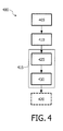
- Fig. 4 presents a flowchart of a method 400 according to the present invention for processing an input three dimensional video signal comprising multiple views.
- the method comprises a step for determining 405 a far disparity estimate indicative of the largest disparity value for the input three dimensional video signal and a near disparity estimate indicative of the smallest disparity value for a spatial region within the input three dimensional video signal.
- the respective disparity estimates may be based on metadata or can alternatively determined based on the image content of the input three dimensional video signal.
- the method further comprises a step of adapting 410 the three dimensional video signal by shifting the input three dimensional video signal backwards by means of a disparity shift based on the far disparity estimate and generating 415 an overlay within the spatial region for the shifted three dimensional video signal based on the near disparity estimate and the disparity shift.
- the method further comprises a step of overlaying 420 the overlay over the shifted three dimensional video signal.
- the step of adapting the input three dimensional video signal may comprise a step for cropping 425 and extending 430 the respective views with padding pixels so as to obtain an altered disparity range.
- N-view multiview image with N even, N-1 or preferably N-views are cropped and extended as described hereinabove.
- Fig 5A presents a system 500 according to the present invention for processing an input three dimensional video signal comprising multiple views.
- the system 500 comprises a disparity determinator 505 for determining a far disparity estimate indicative of the largest disparity value for the input three dimensional video signal and a near disparity estimate indicative of the smallest disparity value for a spatial region within the input three dimensional video signal.
- the disparity determinator 505 may be implemented as a disparity estimator.
- the system further comprises a disparity shifter 510 arranged for adapting the three dimensional video signal by shifting the three dimensional video signal backwards by means of a disparity shift based on the far disparity estimate.
- the system 500 further comprises an overlay generator 515 arranged to generate an overlay within an overlay safe area for the shifted three dimensional video signal based on the near disparity estimate and the disparity shift.
- the system 500 also comprises a video mixer 520 arranged to overlay the overlay over the shifted three dimensional video signal.
- the system 500 as shown in Fig. 5A may be implemented on a Personal Computer or other computing platform for offline processing of content. Alternatively it may be implemented in e.g. a Blu-ray disc playback capable device, or a Set Top Box or a 3D-TV.
- Fig. 5B shows a further system 500 according to the present invention wherein the system is partitioned in an analysis device 502 and a compositing device 503, both devices combined implement the functionality found in the system 500 as presented in Fig. 5A .
- the far and near disparity estimate may be determined for example by using coarse grain disparity analysis of the input three dimensional video signal as described above, or alternatively, by using meta-data provided in the input three dimensional video signal.
- depth and/or parallax of subtitles is supplied as meta-data with the video either per frame or per group of frames.
- the producer of the film or post-production people can produce these meta data by an authoring tool.
- the depth and/or parallax of subtitles is used to position the subtitles at the corresponding depth or parallax in front of the background video.
- depth metadata is any data describing a property of the depth information in the 3D video signal.
- depth metadata is any data describing a property of the depth information in the 3D video signal.
- at least a near value is included in the depth metadata, which is indicative of depths of video data nearest to a user, i.e. elements in the 3D video closest to the viewer when properly displayed on a 3D display.
- the above described near disparity estimate, and said depth and/or parallax of subtitles are examples of the near value.
- Figure 6 shows a system for displaying three dimensional (3D) image data, such as video, graphics or other visual information.
- a 3D source device 40 transfers a 3D video signal 41 to a destination device 50, which is coupled to a 3D display device 60 for transferring a 3D display signal 56.
- the 3D destination device has an input unit 51 for receiving the 3D video signal.
- the device may include an optical disc unit 58 coupled to the input unit for retrieving the 3D video information from an optical record carrier 54 like a DVD or Blu-ray disc.
- the device may include a network interface unit 59 for coupling to a network 45, for example the internet or a broadcast network, such destination device usually being called a set-top box.
- the 3D video signal may be retrieved from a remote media server, e.g. the source device 40.
- the destination device may also be a satellite receiver, or a media player.
- the 3D source device has a processing unit 42 for determining depth metadata indicative of depths occurring in 3D video data 30.
- the 3D video data may be available from storage, from 3D camera's, etc.
- the depth metadata includes a near value indicative of depths of video data nearest to a user, i.e. elements in the 3D video closest to the viewer when properly displayed on a 3D display. Determining depth metadata such as disparity values, and examples of the near value, have been discussed above for multi view data (e.g. the near disparity estimate (A) indicative of the smallest disparity value for a spatial region within the input three dimensional video signal).
- the processing unit generates the 3D video signal comprising the 3D video data, and includes the depth metadata in the 3D video signal.
- the 3D source device may be a server, a broadcaster, a recording device, or an authoring and/or production system for manufacturing record carriers like the Blu-ray Disc.
- Blu-ray Disc supports an interactive platform for content creators. It supports two layers of graphics overlay and two sets of programmable environment for the author to choose from.
- For 3D stereoscopic video there are many formats. The major formats are stereo and the image-plus-depth format. Of these again there are many possible ways in which the content can be formatted to be suitable for use with new and existing 3D displays and distribution formats. This also has an impact on how to extend the graphics systems in the Blu-ray Disc standard to make them suitable to be used in combination with a particular format of the 3D video.
- the production process further comprises the steps of deriving the physical pattern of marks in the tracks which embodies the 3D video signal including the depth metadata, and subsequently shaping the material of the record carrier to provide the tracks of marks on at least one storage layer.
- the 3D destination device has a processing unit 52 coupled to the input unit 51 for processing the 3D information for generating a 3D display signal 56 to be transferred via an output interface unit 55 to the display device, e.g. a display signal according to the HDMI standard, see " High Definition Multimedia Interface; Specification Version 1.3a of Nov 10 2006" available at http://hdmi.org/manufacturer/specification.aspx .
- the processing unit 52 is arranged for generating the image data included in the 3D display signal 56 for display on the display device 60.
- the destination device has an auxiliary processing unit 53 for providing auxiliary data to be combined with the 3D video data on the 3D display.
- Auxiliary data may be any additional graphical image data that is to be combined locally, i.e. in the destination device, with 3D video content, such as subtitles, a logo of a broadcaster, a menu or system message, error codes, news flashes, ticker tape, a further 3D stream such as a commentary, etc.
- subtitles will be used as indicative for every type of auxiliary data.
- the 3D display device 60 is for displaying 3D image data.
- the device has an input interface unit 61 for receiving the 3D display signal 56 including the 3D video data and the auxiliary data transferred from the destination device 50.
- the transferred 3D video data is processed in processing unit 62 for displaying on a 3D display 63, for example a dual or lenticular LCD.
- the display device 60 may be any type of stereoscopic display, also called 3D display, and has a display depth range indicated by arrow 64.
- the processing for providing and positioning the auxiliary data is performed in an embodiment of the display device.
- the 3D video data, and optional auxiliary data are transferred via the display signal 56.
- the auxiliary data may also be locally generated in the display device, e.g. a menu.
- the processing unit 62 now performs the functions of combining the auxiliary data with the 3D video data on the 3D display.
- the processing means 62 may be arranged for the corresponding functions as described below for the processing means 52,53 in the destination device.
- the destination device and the display device are integrated in a single device, where a single set of processing means performs said functions.
- Figure 6 further shows the record carrier 54 as a carrier of the 3D video signal.
- the record carrier is disc-shaped and has a track and a central hole.
- the track constituted by a series of physically detectable marks, is arranged in accordance with a spiral or concentric pattern of turns constituting substantially parallel tracks on an information layer.
- the record carrier may be optically readable, called an optical disc, e.g. a CD, DVD or BD (Blue-ray Disc).
- the information is represented on the information layer by the optically detectable marks along the track, e.g. pits and lands.
- the track structure also comprises position information, e.g. headers and addresses, for indication the location of units of information, usually called information blocks.
- the record carrier 54 carries information representing digitally encoded image data like video, for example encoded according to the MPEG2 or MPEG4 encoding system, in a predefined recording format like the DVD or BD format.
- the processing means 52,53 in the destination device are arranged for executing the following functions.
- the 3D video signal is received by the receiving means 51,58,59.
- the 3D video signal comprises the 3D video data and depth metadata indicative of depths occurring in the 3D video data, which depth metadata includes a near value indicative of depths of video data nearest to a user as described above.
- the processing means 52,53 are arranged for retrieving the depth metadata from the 3D video signal, providing auxiliary data, and positioning the auxiliary data at an auxiliary depth in dependence of the retrieved metadata for displaying the auxiliary data in combination with the 3D video data such that obscuring the auxiliary data by said nearest video data is avoided.
- a problem with overlaying 3D graphics over 3D video is related to how to position the graphics overlay in 3D space without knowing in the playback device the Z ranges of the stereoscopic 3D video in the background. This is typically the case for stereoscopic 3D video in stereo format. The way in which this can be solved depends highly on the format of the 3D video that is used and on how the combined video and graphics is sent to a 3D display device.
- Using metadata to composite 3D images may be based on a complete 3D model including geometry, lighting and such to allow proper compositing of stereoscopic images.
- This approach provides a mechanism to composite 3D images in an authoring environment in the post production stage.
- the problem however with a full 3D model is that this requires a lot of data as 3D information is provided for every pixel in the image.
- Such an approach is less feasible when dealing with stereoscopic images generated in real-time that must be composited on stereoscopic video in a consumer device such as a Blu-ray Disc player or a settop box.
- This depth metadata may include a single byte of data whereby the value indicates the nearest disparity between the left and right view of the stereoscopic video background.
- this depth metadata value may indicate the disparity of any graphics overlay such that if the player composites real-time generated graphics that it should position the graphics at the disparity as indicated in the metadata.
- the proposed depth metadata may consist of one byte per frame or per GOP. If a byte is added to every frame then for a two-hour stereoscopic movie this requires 173 KB of data, this is reasonable. Usage per Group of Pictures would reduce this to (for a 1 second Gop length) 7,2KB of data. Because of the limited size the depth metadata could be extended to include further 3D related fields.
- a further problem to be solved is how to include the depth metadata in the distribution format in such a way that it can be included in a compatible way and that it allows the player to actually be able to use it for real-time compositing.
- the destination device is to be equipped with a so called “Z” compositor which can overlay stereoscopic graphics on stereoscopic video.
- a so called “Z” compositor which can overlay stereoscopic graphics on stereoscopic video.
- the "Z” compositor is included in the processing unit 52.
- the "Z” compositor interprets the depth metadata and from this determines the positioning of the auxiliary data on top of the video in the 3D space.
- the "Z" compositor is a simplified version of a full 3D model based "Z" compositor as mentioned in the prior art.
- the version does not require a full geometric model of both the video and the graphics, but only uses one byte that indicates the depth or disparity range of the stereoscopic video and uses this for the overlay of auxiliary data.
- the depth metadata for the video background is included in a user data message according to a predefined standard transmission format such as MPEG4, e.g. a signaling elementary stream information [SEI] message of a H.264 encoded stream.
- SEI signaling elementary stream information
- the method has the advantage that it is compatible with all systems that rely on the H.264/AVC coding standard (see e.g. ITU-T H.264 and ISO/IEC MPEG-4 AVC, i.e. ISO/IEC 14496-10 standards). New encoders/ decoders could implement the new SEI message whilst existing ones would simply ignore them.
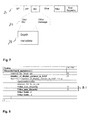
- Figure 7 shows depth metadata in a private user data SEI message.
- An 3D video stream 71 is schematically indicated.
- One element in the stream is the signaling to indicate the parameters of the stream to the decoder, the so called signaling elementary stream information [SEI] message 72.
- SEI signaling elementary stream information
- More specifically the depth metadata 73 could be stored in a user data container.
- the depth metadata may include depth values, disparity values or any other representation of depth information.
- Figure 8 shows a data structure for depth metadata in a 3D video signal.
- the table shown in the Figure defines the syntax of the respective control data packets in the video stream, in particular a GOP_structure_map().
- the data structure defines fields for depth metadata 81, i.e. Video_max_disparity which defines the far value, and the Video_min_disparity which defines the near value; also see Fig.1 for defining disparity values.
- the video min disparity field indicates the nearest object in 3D space towards the viewer and may be used to determine where the overlay any graphics such as subtitles whilst the video max disparity indicates the disparity of an object in the video that is the furthest away from the viewer.
- some documents in the public domain define the maximum disparity value to represent the nearest object; for such definition the sign of the disparity values is to be reversed. At screen depth the disparity is zero irrespective of said definition.
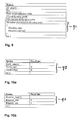
- Figure 9 shows a data structure for depth metadata in a 3D video signal on a record carrier.
- an entry point map may be provided that indicates entry points that allow rendering of the video starting at the entry point.
- the entry point map data structure may be extended by adding depth metadata, which defines the depth values for the fragment of 3D video data starting at the entry point, and, for example, valid until the next entry point.
- depth metadata defines the depth values for the fragment of 3D video data starting at the entry point, and, for example, valid until the next entry point.
- the metadata is stored in an EP-map as shown in the Figure.
- the EP map comprises a table that holds entries to all the valid decoding access points in a stream, i.e. the points where decoding may start.
- the metadata is provided as a XML based description
- this description is transported in the data carousel of a MPEG-2 transport stream.
- An interactive TV application transmitted also in this MPEG-transport stream can make use of this XML based description to determine how to composite stereoscopic graphics onto the video.
- the metadata may be provided as an extension to the playlist.
- the metadata is extended to include minimum and maximum disparity ranges. This would allow overlay of multiple planes of video and graphics.
- the playback device stores the maximum value of the disparity ranges of the depth metadata in a special purpose register. It then uses the nearest value to determine at what depth (or disparity) to overlay the subtitles. The value held in this register changes only gradually over time. This ensures that the subtitles do not constantly change in depth as this can cause eye-strain in the spectator.
- a further extension of the depth metadata is to define several regions in the video frame and to assign depth metadata values specifically to that region.
- selecting a region is performed as follows.
- the display area is subdivided in multiple regions.
- Detecting the depth metadata is performed for each region.
- the frame area is divided into 2 or more regions (e.g. are horizontal stripes) and for each region the min and max depth is added to stream. This gives for freedom for the graphics overlay since it can now be positioned depending also on the region.
- the region depth metadata may be based on spatially filtering the depth values of the multiple regions according to a spatial filter function in dependence of the region.
- the display area is divided in tiles. In each tile the maximum depth is computed separately.
- the auxiliary data can be at a specific depth even if the depth of another object in a different region is significantly closer to the viewer. This also allows subtitles to be composited on a different area and disparity than for example a pop-up menu.
- the "Z" compositor and the amount of data that is stored are extended to accommodate the handing of regions.
- a system using the depth metadata requires creating the metadata and distributing the data, and finally a so called "Z" compositor to read the metadata and composite the auxiliary data over the 3D video, e.g. stereoscopic graphics over the stereoscopic video.
- a disparity estimator and metadata encoder determines the minimum and/or maximum disparity of a frame in the video content and encodes this in the distribution channel. For Blu-ray Disc this may either be in the EP-map or in SEI messages directly in the coded stream, as described above.
- the EP map is typically used during trickplay, it allows the player to jump quickly to the right location in the stream to start decoding the next frame.
- Figure 9 shows a simplified version of this table, extended with a metadata field that carries any metadata associated to the access point.
- Figure 10a shows the format of the metadata field carrying depth metadata.
- the depth of the graphics should be nearer than the depth_max value.
- Figure 10b shows the format of the metadata field carrying disparity data.
- the disparity data 93 is an alternative version of depth metadata that provides minimum and maximum disparity ranges or values, this allows overlay of multiple planes of video.
- a system to apply the invention requires means to create the metadata, to distribute the data and, at the destination, a so called "Z" compositor to read the metadata and composite the stereoscopic graphics over the stereoscopic video.
- the video data processing at the destination device is as follows. For decoding the "Z" compositor determines the frame where the graphics is to be overlaid. It then reads the "depth" or disparity metadata of that frame or if that is not available it uses the value associated with the nearest I-frame (or entry-point). In the next step it determines whether the disparity between the left and right the graphics image is larger (i.e. has a more negative value) or equal to the disparity of the video background images. If the disparity of the stereoscopic graphics is larger or equal to the value indicated in the video metadata, then the Z-compositor just composites the left and right graphics images on to the left and right video frames. If the disparity is smaller then the auxiliary data is farther away and the "Z" compositor adjusts the disparity of the stereoscopic graphics images by performing a linear shift to match the disparity of the graphics with the value indicated in the depth metadata.
- the "Z" compositor composites the graphics on the Left video frame and composites the graphics on the right video frame, but shifted horizontally to the right.
- the amount of shift depends on the value of the "depth” or disparity metadata. Note that the shift required to obtain the desired parallax depends on some parameters such as the viewing distance of the spectator to the display. When calculating a shift as a number of pixels the width and resolution of the spectators display must be known. These parameters may also be included as an option into the "depth” metadata. In an embodiment a standardized or reference set-up is used where for example the display has a width of 1 meter and the spectator is sitting 4 meters from the display.
- subtitles are overlaid on 3D content.
- the primary content exists as stereo (left/right) images; the subtitles also exist as images.
- the embodiment can as well render the subtitles from a suitable description. The embodiment is using the following steps:
- the above method enables selecting the target region by selecting a region of the image data where no depth values occur larger than the auxiliary depth values.
- said selecting may include selecting a period in time for displaying the auxiliary data such that, in the target region, no depth values occur larger than the auxiliary depth values.
- the rendering of the subtitle may be delayed or shifted to allow a more forward object to disappear.
- determining the depth pattern includes detecting depth values in multiple frames of video content, and temporally filtering the depth values according to a temporal filter function. For example a period of time may be considered in which the subtitle itself is to be displayed, or a period slightly longer to avoid objects appearing substantially adjacent to, and more forward than, the subtitle. The period of displaying the subtitle is usually indicated in the display signal.
- determining the depth pattern may include setting a time window for the temporal filter function based on detecting shot boundaries in the multiple frames of video content. This can be implemented as follows.
- the shot boundaries are computed.
- the start images of shots are found by detecting large changes in the image content, using the color histogram of the image.
- the minimum disparity list is detected for the shots according to the shot cuts detected before.
- For each shot the minimum disparity list is then filtered with a suitable time window function (example see below).
- a window function is a function that is zero-valued outside of some chosen interval. For instance, a function that is constant inside the interval and zero elsewhere is called a rectangular window, which describes the shape of its graphical representation.
- the image signal (data) is multiplied by the window function, and the product is also zero-valued outside the interval.
- the depth values of the auxiliary graphical data are allowed to jump at shot cuts if the disparity of the front most object within the region of interest jumps, but it is not allowed to jump within a shot.
- the depth placement between shots can be filtered allowing for smooth transitions at shot boundaries.
- the window is centered at the current position in time, so that both values of the past and future are taken into account. This has the effect of smoothing the values, thus avoiding abrupt changes in the disparity, and of making sure that the overlay is always in front of the 3D content.
- Future values may not be available, e.g. for real time broadcasts, and windowing may be based on past values only. Alternatively a part of the future frames may be stored in a buffer first while applying a small delay in rendering.
- the far value i.e. the minimum parallax shift [PS] or maximum disparity of the video allows to push back the video (decrease the PS or increase the disparity for L + R with the same value) in order to make room for the auxiliary data.
- the far value is taken into account to avoid excessive push back, i.e. the push back should never result in disparity values above the eye-to-eye distance (usually 6 cm) on the screen, i.e. beyond infinity.
- the far value e.g. the maximum disparity
- the destination device it is detected if the maximum value is such that there is no room to (sufficiently) shift the video backwards.
- the processing then temporarily switches to a special mode, in which the main 3D video is displayed as mono video or to mono video with one selected depth having a left and right view shifted such that the mono appears behind the screen.
- An additional parameter in the stream e.g. one byte for a period of the 3D video
- the invention can be implemented in any suitable form including hardware, software, firmware or any combination of these.
- the invention may optionally be implemented at least partly as computer software running on one or more data processors and/or digital signal processors.
- the elements and components of an embodiment of the invention may be physically, functionally and logically implemented in any suitable way. Indeed the functionality may be implemented in a single unit, in a plurality of units or as part of other functional units. As such, the invention may be implemented in a single unit or may be physically and functionally distributed between different units and processors.
Priority Applications (10)
| Application Number | Priority Date | Filing Date | Title |
|---|---|---|---|
| EP09166465A EP2282550A1 (de) | 2009-07-27 | 2009-07-27 | Kombination von 3-D-Video- und Hilfsdaten |
| RU2012106868/08A RU2554465C2 (ru) | 2009-07-27 | 2010-07-20 | Комбинирование 3d видео и вспомогательных данных |
| PCT/IB2010/053302 WO2011013030A1 (en) | 2009-07-27 | 2010-07-20 | Combining 3d video and auxiliary data |
| JP2012522289A JP5647242B2 (ja) | 2009-07-27 | 2010-07-20 | 3dビデオ及び補助データの結合 |
| CN201080033593.1A CN102474638B (zh) | 2009-07-27 | 2010-07-20 | 组合3d视频与辅助数据 |
| US13/386,493 US10021377B2 (en) | 2009-07-27 | 2010-07-20 | Combining 3D video and auxiliary data that is provided when not reveived |
| EP10740392A EP2460360A1 (de) | 2009-07-27 | 2010-07-20 | Kombination von 3-d-video- und hilfsdaten |
| KR1020127004705A KR101716636B1 (ko) | 2009-07-27 | 2010-07-20 | 3d 비디오 및 보조 데이터의 결합 |
| TW099124591A TWI542191B (zh) | 2009-07-27 | 2010-07-26 | 一種於一三維[3d]來源裝置提供一個3d視訊信號以傳送至一3d目的地裝置之方法、用於該方法之3d來源裝置、用於接收一個3d視訊信號之3d目的地裝置、記錄載體、及電腦程式產品 |
| JP2014226195A JP2015092669A (ja) | 2009-07-27 | 2014-11-06 | 3dビデオ及び補助データの結合 |
Applications Claiming Priority (1)
| Application Number | Priority Date | Filing Date | Title |
|---|---|---|---|
| EP09166465A EP2282550A1 (de) | 2009-07-27 | 2009-07-27 | Kombination von 3-D-Video- und Hilfsdaten |
Publications (1)
| Publication Number | Publication Date |
|---|---|
| EP2282550A1 true EP2282550A1 (de) | 2011-02-09 |
Family
ID=40957809
Family Applications (1)
| Application Number | Title | Priority Date | Filing Date |
|---|---|---|---|
| EP09166465A Ceased EP2282550A1 (de) | 2009-07-27 | 2009-07-27 | Kombination von 3-D-Video- und Hilfsdaten |
Country Status (1)
| Country | Link |
|---|---|
| EP (1) | EP2282550A1 (de) |
Cited By (8)
| Publication number | Priority date | Publication date | Assignee | Title |
|---|---|---|---|---|
| CN102447863A (zh) * | 2011-12-20 | 2012-05-09 | 四川长虹电器股份有限公司 | 一种多视点立体视频字幕处理方法 |
| GB2485619A (en) * | 2010-11-12 | 2012-05-23 | Sony Corp | Three dimensional (3D) image duration-related metadata encoding of apparent minimum observer distances (disparity) |
| JP5002066B1 (ja) * | 2011-04-06 | 2012-08-15 | シャープ株式会社 | 画像処理装置、画像処理方法、コンピュータプログラム、および、記録媒体 |
| EP2495979A1 (de) * | 2011-03-01 | 2012-09-05 | Thomson Licensing | Verfahren, Wiedergabevorrichtung und System zur Anzeige stereoskopischer 3D-Videoinformationen |
| EP2540088A1 (de) * | 2010-02-25 | 2013-01-02 | Thomson Licensing | Stereoskopische untertitelung mit disparitätsschätzung und begrenzung der temporären disparitätsvariation |
| CN102917176A (zh) * | 2011-08-05 | 2013-02-06 | 北大方正集团有限公司 | 一种三维立体视差字幕的产生方法 |
| WO2013152784A1 (en) * | 2012-04-10 | 2013-10-17 | Huawei Technologies Co., Ltd. | Method and apparatus for providing a display position of a display object and for displaying a display object in a three-dimensional scene |
| US10097807B2 (en) | 2013-10-10 | 2018-10-09 | Nokia Technologies Oy | Method, apparatus and computer program product for blending multimedia content |
Citations (5)
| Publication number | Priority date | Publication date | Assignee | Title |
|---|---|---|---|---|
| EP0905988A1 (de) * | 1997-09-30 | 1999-03-31 | Kabushiki Kaisha Toshiba | Vorrichtung zur dreidimensionalen Bildwiedergabe |
| EP1599053A2 (de) * | 2004-05-21 | 2005-11-23 | Kabushiki Kaisha Toshiba | 3D Bildanzeigeverfahren und Bildanzeigevorrichtung und Bildaufnahmeverfahren |
| US20070248260A1 (en) * | 2006-04-20 | 2007-10-25 | Nokia Corporation | Supporting a 3D presentation |
| WO2008038205A2 (en) * | 2006-09-28 | 2008-04-03 | Koninklijke Philips Electronics N.V. | 3 menu display |
| WO2008115222A1 (en) | 2007-03-16 | 2008-09-25 | Thomson Licensing | System and method for combining text with three-dimensional content |
-
2009
- 2009-07-27 EP EP09166465A patent/EP2282550A1/de not_active Ceased
Patent Citations (5)
| Publication number | Priority date | Publication date | Assignee | Title |
|---|---|---|---|---|
| EP0905988A1 (de) * | 1997-09-30 | 1999-03-31 | Kabushiki Kaisha Toshiba | Vorrichtung zur dreidimensionalen Bildwiedergabe |
| EP1599053A2 (de) * | 2004-05-21 | 2005-11-23 | Kabushiki Kaisha Toshiba | 3D Bildanzeigeverfahren und Bildanzeigevorrichtung und Bildaufnahmeverfahren |
| US20070248260A1 (en) * | 2006-04-20 | 2007-10-25 | Nokia Corporation | Supporting a 3D presentation |
| WO2008038205A2 (en) * | 2006-09-28 | 2008-04-03 | Koninklijke Philips Electronics N.V. | 3 menu display |
| WO2008115222A1 (en) | 2007-03-16 | 2008-09-25 | Thomson Licensing | System and method for combining text with three-dimensional content |
Non-Patent Citations (2)
| Title |
|---|
| HIGH DEFINITION MULTIMEDIA INTERFACE; SPECIFICATION VERSION 1.3A, 10 November 2006 (2006-11-10), Retrieved from the Internet <URL:http://hdmi.org/manufacturer/specification.aspx> |
| KONRAD ET AL.: "Dense disparity estimation from feature correspondences", IS&T/SPIE SYMPOSIUM ON ELECTRONIC IMAGING STEREOSCOPIC DISPLAYS AND VIRTUAL REALITY SYST., 23 January 2000 (2000-01-23) |
Cited By (18)
| Publication number | Priority date | Publication date | Assignee | Title |
|---|---|---|---|---|
| EP2540088A1 (de) * | 2010-02-25 | 2013-01-02 | Thomson Licensing | Stereoskopische untertitelung mit disparitätsschätzung und begrenzung der temporären disparitätsvariation |
| GB2485619A (en) * | 2010-11-12 | 2012-05-23 | Sony Corp | Three dimensional (3D) image duration-related metadata encoding of apparent minimum observer distances (disparity) |
| GB2485532A (en) * | 2010-11-12 | 2012-05-23 | Sony Corp | Three dimensional (3D) image duration-related metadata encoding of apparent minimum observer distances (disparity) |
| TWI491245B (zh) * | 2011-03-01 | 2015-07-01 | Thomson Licensing | 包括3d串流和3d覆蓋圖形的立體3d視訊資訊之顯示方法及其複製裝置和著作方法及其媒體源器 |
| EP2495979A1 (de) * | 2011-03-01 | 2012-09-05 | Thomson Licensing | Verfahren, Wiedergabevorrichtung und System zur Anzeige stereoskopischer 3D-Videoinformationen |
| WO2012116900A1 (en) * | 2011-03-01 | 2012-09-07 | Thomson Licensing | Method and apparatus for authoring stereoscopic 3d video information, and method and apparatus for displaying such stereoscopic 3d video information |
| US9547928B2 (en) | 2011-03-01 | 2017-01-17 | Thomson Licensing | Method and apparatus for authoring stereoscopic 3D video information, and method and apparatus for displaying such stereoscopic 3D video information |
| CN103503445B (zh) * | 2011-03-01 | 2016-07-06 | 汤姆逊许可公司 | 立体三维视频信息创建方法和装置及其显示方法和装置 |
| CN103503445A (zh) * | 2011-03-01 | 2014-01-08 | 汤姆逊许可公司 | 立体三维视频信息创建方法和装置及其显示方法和装置 |
| JP5002066B1 (ja) * | 2011-04-06 | 2012-08-15 | シャープ株式会社 | 画像処理装置、画像処理方法、コンピュータプログラム、および、記録媒体 |
| WO2012137520A1 (ja) * | 2011-04-06 | 2012-10-11 | シャープ株式会社 | 画像処理装置、画像処理方法、コンピュータプログラム、および、記録媒体 |
| CN102917176A (zh) * | 2011-08-05 | 2013-02-06 | 北大方正集团有限公司 | 一种三维立体视差字幕的产生方法 |
| CN102917176B (zh) * | 2011-08-05 | 2015-08-26 | 新奥特(北京)视频技术有限公司 | 一种三维立体视差字幕的产生方法 |
| CN102447863A (zh) * | 2011-12-20 | 2012-05-09 | 四川长虹电器股份有限公司 | 一种多视点立体视频字幕处理方法 |
| KR20140127287A (ko) * | 2012-04-10 | 2014-11-03 | 후아웨이 테크놀러지 컴퍼니 리미티드 | 삼차원 장면에서 표시 객체의 표시 위치를 제공하고, 표시 객체를 표시하기 위한 방법 및 장치 |
| CN103931177A (zh) * | 2012-04-10 | 2014-07-16 | 华为技术有限公司 | 显示对象在三维场景中的显示方法及设备 |
| WO2013152784A1 (en) * | 2012-04-10 | 2013-10-17 | Huawei Technologies Co., Ltd. | Method and apparatus for providing a display position of a display object and for displaying a display object in a three-dimensional scene |
| US10097807B2 (en) | 2013-10-10 | 2018-10-09 | Nokia Technologies Oy | Method, apparatus and computer program product for blending multimedia content |
Similar Documents
| Publication | Publication Date | Title |
|---|---|---|
| US10021377B2 (en) | Combining 3D video and auxiliary data that is provided when not reveived | |
| US11277600B2 (en) | Switching between 3D video and 2D video | |
| US11310486B2 (en) | Method and apparatus for combining 3D image and graphical data | |
| US9036006B2 (en) | Method and system for processing an input three dimensional video signal | |
| TWI573425B (zh) | 產生三維視訊信號 | |
| EP2433429B1 (de) | Eingangspunkte für 3d-spezialeffekte | |
| EP2282550A1 (de) | Kombination von 3-D-Video- und Hilfsdaten | |
| JP5955851B2 (ja) | 3d画像データの転送 | |
| WO2013150491A1 (en) | Depth helper data | |
| US20150062296A1 (en) | Depth signaling data |
Legal Events
| Date | Code | Title | Description |
|---|---|---|---|
| PUAI | Public reference made under article 153(3) epc to a published international application that has entered the european phase |
Free format text: ORIGINAL CODE: 0009012 |
|
| AK | Designated contracting states |
Kind code of ref document: A1 Designated state(s): AT BE BG CH CY CZ DE DK EE ES FI FR GB GR HR HU IE IS IT LI LT LU LV MC MK MT NL NO PL PT RO SE SI SK SM TR |
|
| AX | Request for extension of the european patent |
Extension state: AL BA RS |
|
| STAA | Information on the status of an ep patent application or granted ep patent |
Free format text: STATUS: THE APPLICATION HAS BEEN REFUSED |
|
| 18R | Application refused |
Effective date: 20101130 |