EP2282255A1 - Mounting structure and mounting method of protection panel having touch input function - Google Patents
Mounting structure and mounting method of protection panel having touch input function Download PDFInfo
- Publication number
- EP2282255A1 EP2282255A1 EP20090754664 EP09754664A EP2282255A1 EP 2282255 A1 EP2282255 A1 EP 2282255A1 EP 20090754664 EP20090754664 EP 20090754664 EP 09754664 A EP09754664 A EP 09754664A EP 2282255 A1 EP2282255 A1 EP 2282255A1
- Authority
- EP
- European Patent Office
- Prior art keywords
- protection panel
- panel
- exterior housing
- touch input
- input function
- Prior art date
- Legal status (The legal status is an assumption and is not a legal conclusion. Google has not performed a legal analysis and makes no representation as to the accuracy of the status listed.)
- Withdrawn
Links
Images




Classifications
-
- G—PHYSICS
- G06—COMPUTING OR CALCULATING; COUNTING
- G06F—ELECTRIC DIGITAL DATA PROCESSING
- G06F1/00—Details not covered by groups G06F3/00 - G06F13/00 and G06F21/00
- G06F1/16—Constructional details or arrangements
- G06F1/1613—Constructional details or arrangements for portable computers
- G06F1/1615—Constructional details or arrangements for portable computers with several enclosures having relative motions, each enclosure supporting at least one I/O or computing function
- G06F1/1622—Constructional details or arrangements for portable computers with several enclosures having relative motions, each enclosure supporting at least one I/O or computing function with enclosures rotating around an axis perpendicular to the plane they define or with ball-joint coupling, e.g. PDA with display enclosure orientation changeable between portrait and landscape by rotation with respect to a coplanar body enclosure
-
- G—PHYSICS
- G06—COMPUTING OR CALCULATING; COUNTING
- G06F—ELECTRIC DIGITAL DATA PROCESSING
- G06F3/00—Input arrangements for transferring data to be processed into a form capable of being handled by the computer; Output arrangements for transferring data from processing unit to output unit, e.g. interface arrangements
- G06F3/01—Input arrangements or combined input and output arrangements for interaction between user and computer
- G06F3/03—Arrangements for converting the position or the displacement of a member into a coded form
- G06F3/033—Pointing devices displaced or positioned by the user, e.g. mice, trackballs, pens or joysticks; Accessories therefor
- G06F3/0354—Pointing devices displaced or positioned by the user, e.g. mice, trackballs, pens or joysticks; Accessories therefor with detection of two-dimensional [2D] relative movements between the device, or an operating part thereof, and a plane or surface, e.g. 2D mice, trackballs, pens or pucks
- G06F3/03547—Touch pads, in which fingers can move on a surface
-
- G—PHYSICS
- G06—COMPUTING OR CALCULATING; COUNTING
- G06F—ELECTRIC DIGITAL DATA PROCESSING
- G06F3/00—Input arrangements for transferring data to be processed into a form capable of being handled by the computer; Output arrangements for transferring data from processing unit to output unit, e.g. interface arrangements
- G06F3/01—Input arrangements or combined input and output arrangements for interaction between user and computer
- G06F3/03—Arrangements for converting the position or the displacement of a member into a coded form
- G06F3/041—Digitisers, e.g. for touch screens or touch pads, characterised by the transducing means
- G06F3/045—Digitisers, e.g. for touch screens or touch pads, characterised by the transducing means using resistive elements, e.g. a single continuous surface or two parallel surfaces put in contact
-
- H—ELECTRICITY
- H05—ELECTRIC TECHNIQUES NOT OTHERWISE PROVIDED FOR
- H05K—PRINTED CIRCUITS; CASINGS OR CONSTRUCTIONAL DETAILS OF ELECTRIC APPARATUS; MANUFACTURE OF ASSEMBLAGES OF ELECTRICAL COMPONENTS
- H05K7/00—Constructional details common to different types of electric apparatus
- H05K7/14—Mounting supporting structure in casing or on frame or rack
-
- Y—GENERAL TAGGING OF NEW TECHNOLOGICAL DEVELOPMENTS; GENERAL TAGGING OF CROSS-SECTIONAL TECHNOLOGIES SPANNING OVER SEVERAL SECTIONS OF THE IPC; TECHNICAL SUBJECTS COVERED BY FORMER USPC CROSS-REFERENCE ART COLLECTIONS [XRACs] AND DIGESTS
- Y10—TECHNICAL SUBJECTS COVERED BY FORMER USPC
- Y10T—TECHNICAL SUBJECTS COVERED BY FORMER US CLASSIFICATION
- Y10T29/00—Metal working
- Y10T29/49—Method of mechanical manufacture
- Y10T29/49002—Electrical device making
-
- Y—GENERAL TAGGING OF NEW TECHNOLOGICAL DEVELOPMENTS; GENERAL TAGGING OF CROSS-SECTIONAL TECHNOLOGIES SPANNING OVER SEVERAL SECTIONS OF THE IPC; TECHNICAL SUBJECTS COVERED BY FORMER USPC CROSS-REFERENCE ART COLLECTIONS [XRACs] AND DIGESTS
- Y10—TECHNICAL SUBJECTS COVERED BY FORMER USPC
- Y10T—TECHNICAL SUBJECTS COVERED BY FORMER US CLASSIFICATION
- Y10T292/00—Closure fasteners
- Y10T292/08—Bolts
- Y10T292/1099—Screw
Definitions
- the present invention relates to a protection panel with a touch input function applied to, for example: portable information terminal, such as PDA and handheld terminal; OA equipments, such as copy machine and facsimile machine; smartphone, mobile phone, portable gaming device, electronic dictionary, car navigation system, compact PC; and various household appliances, and particularly relates to a structure and method for firmly mounting the protection panel to an exterior housing.
- portable information terminal such as PDA and handheld terminal
- OA equipments such as copy machine and facsimile machine
- smartphone mobile phone, portable gaming device, electronic dictionary, car navigation system, compact PC
- various household appliances and particularly relates to a structure and method for firmly mounting the protection panel to an exterior housing.
- An exterior housing in an electronic device such as mobile phone and smartphone is typically formed of a combination of a front exterior housing and a rear exterior housing each made of a synthetic resin, and to a surface of the front exterior housing a protection panel is fixed in order to protect a crystalline liquid display window.
- a protection panel a clear and colorless resin panel has been conventionally used.
- a recent trend is that a decoration, such as printed decoration rims, is introduced along with the emphasis of fashion aspect of the electronic devices.
- the protection panel as shown in Fig. 17 has been expected to have an input device function as a next interface of the mobile phone, and the technique is described, for example, in Patent Document 1.
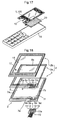
- a protection panel 1 with a touch input function includes: a lower electrode panel 3 having a non-flexible protection panel body, and on an upper face thereof, a lower transparent electrode 5 and lower circuits 7a,7b provided in a portion surrounding the lower transparent electrode 5; an upper electrode sheet 2a having a flexible transparent insulation film, and on a lower face thereof, an upper transparent electrode 4 provided at a position opposingly corresponding to a position of the lower transparent electrode 5, and upper circuits 6a-6d,7c,7d provided in a portion surrounding the upper transparent electrode 4; and a decorative sheet 2b having a flexible transparent insulation film and a decorative layer with a picture 17 for concealing the lower circuits 7a,7b and the upper circuits 6a-6d,7c,7d to form a transparent window 18.
- the decorative sheet 2b is stuck together with an entire front face of the upper electrode sheet 2a (hereinafter, lamination of the upper electrode sheet 2a and the decorative sheet 2b is referred to as "movable sheet 2").
- movable sheet 2 lamination of the upper electrode sheet 2a and the decorative sheet 2b is referred to as "movable sheet 2".
- Fig. 19 is a cross-sectional view showing one example of a mounting structure in the front exterior housing using a protection panel with a touch input function.
- a panel fitting portion 22 is formed in such a manner that a protection panel 100 with a touch input function can be fitted thereinto.
- a depth of the panel fitting portion 22 is approximately the same as a thickness of the protection panel 100 with a touch input function, so that an outer face of the protection panel 100 is in the same plane as a portion of the front exterior housing 19 surrounding the outer face.
- a bottom face of the panel fitting portion 22 there is provided an opening or recess 23 which is one size smaller than the bottom face, in such a manner that a display unit 20 is viewable from outside through a transparent window.
- the rim portion 22a of the bottom face supports a rim portion of the protection panel 100 with a touch input function on which the decorative layer is provided.
- the protection panel 100 with a touch input function is fixed to the bottom face of the panel fitting portion 22 of the front exterior housing 19 using an adhesive or double-stick tape 24. Therefore, the protection panel 100 with a touch input function is not satisfactorily fixed, and if an electronic device having such a mounting structure is used at high temperature and humidity, the protection panel 100 with a touch input function may warp and easily peel from the front exterior housing 19. Even though the protection panel 100 does not peel, the outer face of the protection panel 100 cannot be in the same plane as the portion of the front exterior housing surrounding the outer face, and a step is sometimes generated between the outer face and the surrounding portion.
- the present invention was made with the view toward solving the problems of the prior art techniques, and the present invention provides a mounting structure and a mounting method for more firmly fixing the protection panel with a touch input function to the exterior housing.
- protection panel for mounting a protection panel with a touch input function for protecting an electronic device display window
- protection panel is mainly formed of a protection panel body made of a resin plate
- the protection panel is fitted into a panel fitting portion of an exterior housing from outside so that an outer face of the protection panel is in the same plane as a portion of the exterior housing surrounding the outer face
- nuts each having a female thread formed in an inner periphery thereof are attached to respective nut mounting holes formed in a back side rim portion of the protection panel body, and male screws are screwed into the respective female threads of the nuts through respective through-holes formed in the panel fitting portion of the exterior housing.
- the male screws are screwed into the nuts attached to the nut mounting holes formed in the back side rim portion of the protection panel. Since the protection panel body is screwed from inside the panel fitting portion of the exterior housing in this manner, the protection panel with a touch input function can be more firmly fixed to the exterior housing. In addition, if the male screws are directly screwed into the holes formed in the back side rim portion of the protection panel and the protection panel is thin, a screw hole formed in the protection panel may not have a sufficient length to firmly fix the protection panel to the exterior housing.
- the nuts attached to the nut mounting holes formed in the back side rim portion of the protection panel secures a sufficient length of the screw hole to be engaged with the male screw, and thus the protection panel is firmly fixed to the exterior housing.
- the protection panel with a touch input function includes: a lower electrode panel including the protection panel body which is non-flexible, a lower transparent electrode, and a lower circuit provided in a portion surrounding the lower transparent electrode, the lower transparent electrode and the lower circuit being formed on an upper face of the protection panel body; an upper electrode sheet including a flexible transparent insulation film, an upper transparent electrode provided at a position opposingly corresponding to a position of the lower transparent electrode, and an upper circuit provided in a portion surrounding the upper transparent electrode, the upper transparent electrode and the upper circuit being formed on a lower face of the insulation film, the upper electrode sheet being stuck to the lower electrode panel at rim portions with a gap between the electrodes; and a decorative sheet including a flexible transparent insulation film, a decorative layer for concealing the lower circuit and the upper circuit to form a transparent window, the decorative layer being provided on at least one face of the insulation film, the decorative sheet being stuck to the upper face of an upper electrode sheet.
- the decorative sheet has the decorative layer on at least one face of the flexible transparent insulation film and is stuck to the upper face of the upper electrode sheet, and thus nut mounting holes, nuts and male screws formed in the back side rim portion of the protection panel can be surely concealed from view.
- the method includes: a step of attaching nuts each having a female thread formed in an inner periphery thereof to respective mounting holes formed in a back side rim portion of the protection panel body; a step of fitting the protection panel into the panel fitting portion of the exterior housing from outside; and a step of screwing male screws into the respective female threads of the nuts through respective through-holes formed in the panel fitting portion of the exterior housing.
- the male screws are screwed into the nuts attached to the nut mounting holes formed in the back side rim portion of the protection panel. Since the protection panel body is screwed from inside the panel fitting portion of the exterior housing in this manner, the protection panel with a touch input function can be more firmly fixed to the exterior housing. In addition, if the male screws are directly screwed into the holes formed in the back side rim portion of the protection panel and the protection panel is thin, a screw hole formed in the protection panel may not have a sufficient length to firmly fix the protection panel to the exterior housing.
- the nuts attached to the nut mounting holes formed in the back side rim portion of the protection panel secures a sufficient length of the screw hole to be engaged with the male screw, and thus the protection panel is firmly fixed to the exterior housing.
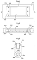
- Fig. 1 is a plan view showing one embodiment of a structure for mounting a protection panel with a touch input function according to the present invention.
- Fig. 2 is a bottom view showing the mounting structure of Fig. 1.
- Fig. 3 is a cross-sectional view of the mounting structure of Fig. 1 taken along a line III-III.
- a protection panel 1 with a touch input function for protecting the electronic device display window shown in Figs. 1 - 3 is mainly formed of a protection panel body made of a resin plate. Components other than the protection panel body, which is the lowermost layer of the protection panel 1, will be described later, and herein only the protection panel body will be described.
- the protection panel body is typically a resin plate in an approximate rectangle having a thickness of approximately 0.5 mm - 1.0 mm. Examples of the material include engineering plastics, such as polycarbonates, polyamides, and polyetherketones; and acrylic, polyethylene terephthalate, and polybutylene terephthalate.
- nuts 33 are attached to a back side rim portion of the protection panel body, by press-fitting or the like.
- the nut 33 is used for the purpose of indirectly making a female thread, when it is difficult to tap a female thread in a material due to a property of the material.
- the protection panel body of the protection panel 1 with a touch input function is a thin plate made of resin, and a thickness may be as thin as approximately 0.5 mm. In the case of such a thin plate, it is difficult to tap a female thread with a required length, and in order to obtain the female thread with the required length, the nut 33 separate from the protection panel body is attached to the back side rim portion of the protection panel body. In addition, a sufficient strength can be secured as compared with the case where a female thread is directly tapped in the protection panel body made of resin.
- FIG. 10 (a) and (b) are sequential diagrams showing one embodiment of a step for attaching the nuts 33 to the protection panel body of the protection panel 1 with a touch input function, by press-fitting the nuts 33 into the respective nut mounting holes 1a formed in the back side rim portion.
- a back side of the protection panel body which is the lowermost layer of the protection panel 1, is oriented upward.
- the attachment of the nut 33 to the protection panel 1 may be performed by, as shown in Figs. 11 and 12 , threading an outer periphery of the nut 33, and screwing and fitting the nut 33 into the nut mounting holes 1a.
- Fig. 11 both the outer periphery of the nut 33 and the nut mounting hole 1a are threaded.
- Fig. 12 the outer periphery of the nut 33 is threaded while the nut mounting hole 1a is not. In this case, an outer diameter of the nut 33 is made smaller than an inner diameter of the nut mounting hole 1a, and the nut 33 is frictionally screwed and fitted into the nut mounting hole 1a.
- the nut 33 may be attached to the protection panel 1 by adhering the nut 33 to the nut mounting hole 1a using various adhesives or the like.
- the nut mounting hole 1a may penetrate through the protection panel body, but should never reach an outer face of the protection panel 1. The reason is that, since the outer face of the protection panel 1 forms a portion of the housing in such a manner that the outer face is in the same plane as a portion of the housing surrounding the outer face, the exposure of the nut mounting hole 1a to outside notably deteriorates the appearance. In addition, it is preferable that the nut mounting hole 1a does not penetrate through the protection panel body, which is the lowermost layer of the protection panel 1. The reason is that, if the nut mounting hole 1a penetrates through the protection panel body, a wiring space in a front face of the protection panel body for imparting a touch input function becomes small.
- a distance between a rim of the nut mounting hole 1a and a contour of the protection panel body is 0.5 mm or more. If this distance is less than 0.5 mm, satisfactory peel strength cannot be obtained with respect to the attached nuts 33.
- the nut 33 typically includes a cylindrical barrel portion 33b having a female thread 33a formed in an inner periphery thereof; and a protrusion 33d or recess for engagement which is formed in a portion on an outer periphery at a position close to one end, in other words, a portion to be buried in the base material (in the present invention, a thin plate made of resin as the protection panel body).
- the female thread 33a may be formed to have a diameter of 1.5mm, and a length of 2.5mm. It should be noted that the nut may be selected from a wide range of commercially available nuts, which may be called various names other than press-fit nut. Examples of the material for the nut 33 include iron, stainless steel, brass and hard plastic.
- Fig. 6 is a diagram showing one embodiment of the press-fit nut 33 used in the present invention.
- the press-fit nut 33 shown in Fig. 6 includes: the cylindrical barrel portion 33b having the female thread 33a formed in the inner periphery thereof; and the protrusion 33d for engagement which is formed in a portion on an outer periphery at a position close to one end, in other words, a portion to be buried in the protection panel body.
- a flange 33c which determines a buried amount of the press-fit nut 33 into the protection panel body is integrally formed with the press-fit nut 33.
- the flange 33c extends from the barrel portion 33b to be buried by approximately 1 - 2 mm.
- the female thread 33a is provided in an inner wall of the cylindrical barrel portion 33b. With the female thread 33a, a male screw is engaged so as to fix other components.
- the press-fitting attachment of the press-fit nut 33 to the protection panel 1 is performed by applying ultrasonic vibration and pressure to the press-fit nut 33 during press-fitting.
- ultrasonic vibration and pressure When the ultrasonic vibration and pressure is applied to the press-fit nut 33, frictional heat is generated at an interface between the press-fit nut 33 and the nut mounting hole 1a, and a portion surrounding the nut mounting hole 1a will be molten or deformed.
- the protrusion 33d for fastening provided on the outer periphery of the press-fit nut 33 is received in a portion surrounding the nut mounting hole 1a, and strengthen the bonding between the protection panel body and the press-fit nut 33 after the portion surrounding the nut mounting hole 1a is re-solidified.
- the molten resin enters the recess. It may be sufficient if the protrusion 33d or recess for fastening has a size of approximately 0.1 mm.
- the protrusion 33d is formed of two ridges, and alternatively, may be formed of one ridge (see Fig. 7 (b) ) or three or more ridges.
- the flange 33c is formed in only a portion of the outer periphery of the press-fit nut 33 adjacent to the protrusion 33d. Alternatively, the flange 33c may be extended to the other end of the outer periphery (see Fig. 7 (a) ).
- the profile of the flange 33c may be a polygonal shape with approximately even sides (see Fig. 8 (a) ).
- the profile of the flange 33c may be a circular shape with a portion thereof being cut away to give linear portions, for example, a circular shape having a pair of linear portions arranged in parallel (see Fig. 8 (b) ).
- the profile of the flange 33c is a polygonal shape or a circular shape with linear portions, as shown in Fig.
- a recess 1b having a dimension corresponding to the flange 33c may be formed in advance in the protection panel body made of a resin plate, and by accommodating the flange 33c in the recess 1b, the flange 33c can be prevented from rotating during the screwing of a male screw 34, and thus a reliable fixation can be obtained.
- the position and the number of the nut 33 may appropriately selected depending on the dimension and shape of the protection panel body and the material of the protection panel body and an exterior housing 32.
- the nuts 33 fitted into the respective nut mounting holes 1a and depicted with broken lines in Fig. 1 are arranged at positions adjacent to only opposing shorter sides of the back side rim portion of the protection panel body.
- a difference in expansion rate as compared with the exterior housing 32 or the like in order to prevent imbalance in force to secure the protection panel body, it is preferable to provide the nuts 33 also at positions adjacent to long sides of the protection panel body.
- the protection panel 1 with a touch input function as described above to which the nuts 33 are attached can be fitted and mounted from outside, as shown in Fig. 3 .
- the exterior housing 32 mounted with the protection panel 1 with a touch input function may be used in portable information terminal, such as PDA and handheld terminal; OA equipments, such as copy machine and facsimile machine; smartphone, mobile phone, portable gaming device, electronic dictionary, car navigation system, compact PC; and various household appliances, and is provided with a panel fitting portion 32a configured to allow the protection panel 1 with a touch input function to be fitted thereinto from outside (see Figs. 4 and 5 ).
- Examples of the material for the exterior housing 32 include polymethyl methacrylate (PMMA), acrylonitrile-styrene copolymer resin (AS), acrylonitrile-butadiene-styrene copolymer resin (ABS), cellulose propionate resin, polycarbonate resin (PC), polystyrene resin (PS), polyester resin, polyethylene resin and polymer alloy thereof.
- PMMA polymethyl methacrylate
- AS acrylonitrile-styrene copolymer resin
- ABS acrylonitrile-butadiene-styrene copolymer resin
- PC polycarbonate resin
- PS polystyrene resin
- polyester resin polyethylene resin and polymer alloy thereof.
- the depth of the panel fitting portion 32a of the exterior housing 32 shown in Figs. 4 and 5 is set so as to be approximately equal to the thickness of the protection panel 1 with a touch input function, and the outer face of the fitted protection panel 1 can be in the same plane as the portion of the exterior housing surrounding the outer face.
- a recess 32c is formed in a bottom face of the panel fitting portion 32a so as to receive a display unit 20, and a rim portion of the bottom face supports the protection panel 1 with a touch input function.
- through-holes 32b are formed so as to correspond to the female threads 33a of the nut 33 press-fitted into the back side rim portion of the protection panel 1 (see Figs. 4 and 5 ).
- FIG. 14 (a) and (b) are sequential diagrams showing one embodiment of a step for fitting the protection panel 1 with a touch input function into the panel fitting portion 32a of the exterior housing 32 from outside.
- FIG. 15 (a) and (b) are sequential diagrams showing one embodiment of a step for screwing the male screws 34 each having a head portion with a larger diameter than that of the through-hole 32b into the respective female threads 33a of the nuts 33, through the respective through-holes 32b formed in the panel fitting portion 32a of the exterior housing 32.
- the male screws 34 are first inserted into the through-hole 32b, from inside relative to the exterior housing 32 toward the protection panel 1 with a touch input function.
- the male screw 34 proceeds while making a rotation. Then, the male screws 34 reach the respective nuts 33 through the respective through-holes 32b. Subsequently, these male screws 34 are screwed into the respective nuts 33.
- the male screw 34 has the head portion with a larger diameter than that of the through-hole 32b, and is made of materials such as iron, stainless steel, brass and hard plastic, like the nut 33.
- these nuts 33 and the head portions of the respective male screws 34 sandwich and fix the panel fitting portion 32a of the exterior housing 32 therebetween (see Fig. 15 (b) and Fig. 2 ).
- the protection panel 1 with a touch input function is fitted and mounted from outside into the panel fitting portion 32a of the exterior housing 32.
- a female thread is provided to the through-hole 32b of the exterior housing 32, the exterior housing 32 and the male screw 34 becomes unified, allowing a further strengthened fixation.
- a size of the head portion of the male screw 34 may be set to approximately the same as a diameter of the through-hole 32b.
- the nut 33 shown in Figs. 3 and 6 - 9 is for obtaining a female thread with the required length by attaching the nut 33 while the nut 33 protrudes from the back side rim portion of the thin plate as the protection panel body. It is preferable that the protruding portion of the nut 33 is received in a recess 32d formed in the panel fitting portion 32a of the exterior housing 32 (see Fig. 5 ), and in this case, the protection panel 1 with a touch input function can be stably mounted. It should be noted that, during the fitting of the protection panel 1 with a touch input function as shown in Fig. 14 (a) , the protection panel 1 is bent as less as possible.
- the electronic device can be made thinner by the amount of the reception.
- a recess 32e for receiving the head portion of the male screw 34 be made in the exterior housing 32 (see Fig. 5 ), and in this case, the electronic device can be made further thinner by the amount of the reception of the head portion of the male screw 34.
- an opening 32f for exposing a screen of the display unit 20 may be formed.
- the protection panel 1 with a touch input function includes: a lower electrode panel 3 having the protection panel body, and on an upper face thereof, a lower transparent electrode 5 and lower circuits 7a,7b provided in a portion surrounding the lower transparent electrode 5; an upper electrode sheet 2a having a flexible transparent insulation film, and on a lower face thereof, an upper transparent electrode 4 provided at a position opposingly corresponding to a position of the lower transparent electrode 5, and upper circuits 6a-6d,7c,7d provided in a portion surrounding the upper transparent electrode 4; and a decorative sheet 2b having a flexible transparent insulation film and a decorative layer with a picture 17 for concealing the lower circuits 7a,7b and the upper circuits 6a-6d,7c,7d to form a transparent window 18.
- the material of the protection panel body is as described above.
- a film made of engineering plastics such as polycarbonates, polyamides, and polyetherketones; or acrylic, polyethylene terephthalate and polybutylene terephthalate, to thereby obtain the lower electrode panel 3.
- examples of the material of the flexible transparent insulation film of the upper electrode sheet 2a include engineering plastics, such as polycarbonates, polyamides and polyetherketones; and acrylic, polyethylene terephthalate, and polybutylene terephthalate.
- Each of the transparent electrodes 4,5 in a rectangular shape is formed as a film of metal oxide, such as tin oxide, indium oxide, antimony oxide, zinc oxide, cadmium oxide, and indium tin oxide (ITO) or a composite membrane formed mainly of the metal oxide described above, or a film of metal, such as gold, silver, copper, tin, nickel, aluminum, and palladium, by vacuum deposition method, sputtering method, ion plating method, or CVD method.
- metal oxide such as tin oxide, indium oxide, antimony oxide, zinc oxide, cadmium oxide, and indium tin oxide (ITO)
- ITO indium tin oxide
- a composite membrane formed mainly of the metal oxide described above or a film of metal, such as gold, silver, copper, tin, nickel, aluminum, and palladium
- the upper electrode sheet 2a has the upper transparent electrode 4 and strip-shaped parallel bus bars 6a,6b as upper circuit made of a conductive paste of metal, e.g., gold, silver, copper and nickel, or alternatively, a paste of carbon.
- the lower electrode panel 3 has the lower transparent electrode 5 and strip-shaped bus bars 7a,7b as lower circuit orthogonal to the bus bars 6a,6b. Examples of a method for fabricating each of the strip-shaped bus bars 6a,6b,7a,7b include printing method, such as screen printing, offset printing, gravure printing, and flexographic printing; photoresist method; and brush painting method.
- bus bars 6a,6b,7a,7b extend to a single connecting portion 8 provided in a rim portion of the upper electrode sheet 2a.
- the bus bars 6a,6b on the upper electrode sheet 2a extend to electrode ends 6d,6c, respectively, of the connecting portion 8.
- the bus bars 7a,7b of the lower electrode panel 3 extend to the portions 7e,7f in the lower circuit, respectively, which are then connected using a conductive adhesive (not shown) to electrode ends 7c,7d, respectively, formed in the connecting portion 8 of the upper electrode sheet 2a in parallel with the electrode ends 6d,6c.
- Through holes 9a - 9d are formed in the lower electrode panel 3 so as to correspond to the respective electrode ends 6c,7c,6d,7d in the connecting portion 8.
- an FPC flexible print circuit board
- the FPC is conductive with the electrode ends 6c,7c,6d,7d.
- the FPC there is no limitation with respect to the FPC, as long as electric signals can be taken out from the through holes 9a - 9d.
- One preferable example is an FPC 10 having four metal pins 11 - 14 standing on a connecting end side of the FPC which pins correspond to the respective through holes 9a - 9d.
- the FPC is not limited to those described in the paragraph of "Background art".
- the decorative sheet 2b is formed of a flexible transparent insulation film including engineering plastic, such as polycarbonates, polyamides and polyetherketones; or film such as those made of acrylic, polyethylene terephthalate and polybutylene terephthalate, on which a decorative layer is formed with the picture 17 so as to conceal a portion surrounding the transparent window 18, i.e., the upper circuit, the lower circuit and the like.
- engineering plastic such as polycarbonates, polyamides and polyetherketones
- film such as those made of acrylic, polyethylene terephthalate and polybutylene terephthalate
- a colored ink may be used, which includes: resins, such as polyvinyl resin, polyamide resin, polyester resin, polyacrylic resin, polyurethane resin, polyvinyl acetal resin, polyester urethane resin, or alkyd resin as a binder; and pigment or dye of an appropriate color as a coloring agent.
- resins such as polyvinyl resin, polyamide resin, polyester resin, polyacrylic resin, polyurethane resin, polyvinyl acetal resin, polyester urethane resin, or alkyd resin as a binder
- pigment or dye of an appropriate color as a coloring agent examples include regular printing method, such as screen printing, offset printing, gravure printing, and flexographic printing.
- the offset printing and the gravure printing are suitable.
- the decorative layer may also be a metal film layer, or alternatively, a combination of a picture print layer and a metal film layer.
- the metal film layer as the decorative layer is for expressing metallic luster and is formed by vacuum deposition method, sputtering method, ion plating method, plating method or the like.
- a metal is used which may be selected from, for example, aluminum, nickel, gold, platinum, ferrochrome, copper, tin, indium, silver, titanium, lead, and zinc, and alloys or compounds thereof.
- a thickness of the metal film layer is approximately 0.05 ⁇ m.
- the decorative sheet 2b is stuck together with an entire front face of the upper electrode sheet 2a, to form a movable sheet 2.
- the movable sheet 2 As a whole is bent downward, and as a result, the transparent electrodes 4,5 provided on the opposing faces of the upper electrode sheet 2a and the lower electrode panel 3 are brought into contact, and thus an input position is detected.
- the adhesion layer to be used for sticking may be made of, for example, polyacrylic resin, polystyrene resin, polyamide resin, vinyl chloride, vinyl acetate, acrylic copolymer or the like.
- Examples of a method for fabricating the adhesion layer 5d include regular printing method, such as screen printing, offset printing, gravure printing, and flexographic printing.
- the protection panel 1 with a touch input function shown in Fig. 18 is used for the resistive film type touch panel.
- the protection panel 1 with a touch input function according to the present invention may be used for other types, for example a capacitance type touch panel.
- the protection panel body is used as the lowermost layer, and there may be provided a decorative sheet having a decorative layer with a picture for concealing a rim portion to form a transparent window.
- the structure and method for mounting the protection panel according to the present invention can be applicable to a protection panel with a touch input function used in portable information terminal, such as PDA and handheld terminal; OA equipments, such as copy machine and facsimile machine; smartphone, mobile phone, portable gaming device, electronic dictionary, car navigation system, compact PC; and various household appliances.
Landscapes
- Engineering & Computer Science (AREA)
- Theoretical Computer Science (AREA)
- General Engineering & Computer Science (AREA)
- Physics & Mathematics (AREA)
- Human Computer Interaction (AREA)
- General Physics & Mathematics (AREA)
- Mathematical Physics (AREA)
- Computer Hardware Design (AREA)
- Microelectronics & Electronic Packaging (AREA)
- Position Input By Displaying (AREA)
Abstract
A mounting structure includes a protection panel (1) with a touch input function for protecting an electronic device display window, mainly formed of the protection panel body made of a resin plate, and a panel fitting portion (32a) of an exterior housing (32) into which the protection panel (1) is fitted from outside so that an outer face of the protection panel (1) is in the same plane as a portion of the exterior housing surrounding the outer face. In this structure, nut mounting holes are formed in a back side rim portion of the protection panel body and nuts (33) each having a female thread formed in an inner periphery thereof are attached to the respective nut mounting holes, and male screws (34) are screwed into the respective female threads of the nuts (33) through through-holes (32b) formed in the panel fitting portion (32a) of the exterior housing (32).
Description
- The present invention relates to a protection panel with a touch input function applied to, for example: portable information terminal, such as PDA and handheld terminal; OA equipments, such as copy machine and facsimile machine; smartphone, mobile phone, portable gaming device, electronic dictionary, car navigation system, compact PC; and various household appliances, and particularly relates to a structure and method for firmly mounting the protection panel to an exterior housing.
- An exterior housing in an electronic device, such as mobile phone and smartphone is typically formed of a combination of a front exterior housing and a rear exterior housing each made of a synthetic resin, and to a surface of the front exterior housing a protection panel is fixed in order to protect a crystalline liquid display window. As the protection panel, a clear and colorless resin panel has been conventionally used. A recent trend is that a decoration, such as printed decoration rims, is introduced along with the emphasis of fashion aspect of the electronic devices.
- In addition, recently, the protection panel as shown in
Fig. 17 has been expected to have an input device function as a next interface of the mobile phone, and the technique is described, for example, inPatent Document 1. - The protection panel with a touch input function for protecting the electronic device display window will be further described in detail using the exploded view of
Fig. 18 . Referring to this drawing, aprotection panel 1 with a touch input function includes: alower electrode panel 3 having a non-flexible protection panel body, and on an upper face thereof, a lowertransparent electrode 5 andlower circuits transparent electrode 5; anupper electrode sheet 2a having a flexible transparent insulation film, and on a lower face thereof, an uppertransparent electrode 4 provided at a position opposingly corresponding to a position of the lowertransparent electrode 5, andupper circuits 6a-6d,7c,7d provided in a portion surrounding the uppertransparent electrode 4; and adecorative sheet 2b having a flexible transparent insulation film and a decorative layer with apicture 17 for concealing thelower circuits upper circuits 6a-6d,7c,7d to form atransparent window 18. - The
decorative sheet 2b is stuck together with an entire front face of theupper electrode sheet 2a (hereinafter, lamination of theupper electrode sheet 2a and thedecorative sheet 2b is referred to as "movable sheet 2"). When a surface of thedecorative sheet 2b is pressed with a finger, stylus or the like, themovable sheet 2 as a whole is bent downward, and as a result, thetransparent electrodes upper electrode sheet 2a andlower electrode panel 3 are brought into contact, and thus an input position is detected. -
Fig. 19 is a cross-sectional view showing one example of a mounting structure in the front exterior housing using a protection panel with a touch input function. As shown inFig. 19 , in a frontexterior housing 19, apanel fitting portion 22 is formed in such a manner that aprotection panel 100 with a touch input function can be fitted thereinto. A depth of thepanel fitting portion 22 is approximately the same as a thickness of theprotection panel 100 with a touch input function, so that an outer face of theprotection panel 100 is in the same plane as a portion of the frontexterior housing 19 surrounding the outer face. In addition, in a bottom face of thepanel fitting portion 22, there is provided an opening orrecess 23 which is one size smaller than the bottom face, in such a manner that adisplay unit 20 is viewable from outside through a transparent window. Therim portion 22a of the bottom face supports a rim portion of theprotection panel 100 with a touch input function on which the decorative layer is provided. -
- Patent Document 1: published PCT international publication for patent application in Japanese,
WO2005/064451 - However, in the conventional structure for mounting the protection panel with a touch input function, the
protection panel 100 with a touch input function is fixed to the bottom face of thepanel fitting portion 22 of the frontexterior housing 19 using an adhesive or double-stick tape 24. Therefore, theprotection panel 100 with a touch input function is not satisfactorily fixed, and if an electronic device having such a mounting structure is used at high temperature and humidity, theprotection panel 100 with a touch input function may warp and easily peel from the frontexterior housing 19. Even though theprotection panel 100 does not peel, the outer face of theprotection panel 100 cannot be in the same plane as the portion of the front exterior housing surrounding the outer face, and a step is sometimes generated between the outer face and the surrounding portion. - Accordingly, the present invention was made with the view toward solving the problems of the prior art techniques, and the present invention provides a mounting structure and a mounting method for more firmly fixing the protection panel with a touch input function to the exterior housing.
- In one aspect of the structure of the present invention for mounting a protection panel with a touch input function for protecting an electronic device display window which protection panel is mainly formed of a protection panel body made of a resin plate, in which structure the protection panel is fitted into a panel fitting portion of an exterior housing from outside so that an outer face of the protection panel is in the same plane as a portion of the exterior housing surrounding the outer face, nuts each having a female thread formed in an inner periphery thereof are attached to respective nut mounting holes formed in a back side rim portion of the protection panel body, and male screws are screwed into the respective female threads of the nuts through respective through-holes formed in the panel fitting portion of the exterior housing.
- With this configuration, the male screws are screwed into the nuts attached to the nut mounting holes formed in the back side rim portion of the protection panel. Since the protection panel body is screwed from inside the panel fitting portion of the exterior housing in this manner, the protection panel with a touch input function can be more firmly fixed to the exterior housing.
In addition, if the male screws are directly screwed into the holes formed in the back side rim portion of the protection panel and the protection panel is thin, a screw hole formed in the protection panel may not have a sufficient length to firmly fix the protection panel to the exterior housing. However, with the present configuration, even when the thickness of the protection panel is thin, the nuts attached to the nut mounting holes formed in the back side rim portion of the protection panel secures a sufficient length of the screw hole to be engaged with the male screw, and thus the protection panel is firmly fixed to the exterior housing. - In a second aspect of the structure for mounting a protection panel with a touch input function of the present invention, the protection panel with a touch input function includes: a lower electrode panel including the protection panel body which is non-flexible, a lower transparent electrode, and a lower circuit provided in a portion surrounding the lower transparent electrode, the lower transparent electrode and the lower circuit being formed on an upper face of the protection panel body; an upper electrode sheet including a flexible transparent insulation film, an upper transparent electrode provided at a position opposingly corresponding to a position of the lower transparent electrode, and an upper circuit provided in a portion surrounding the upper transparent electrode, the upper transparent electrode and the upper circuit being formed on a lower face of the insulation film, the upper electrode sheet being stuck to the lower electrode panel at rim portions with a gap between the electrodes; and a decorative sheet including a flexible transparent insulation film, a decorative layer for concealing the lower circuit and the upper circuit to form a transparent window, the decorative layer being provided on at least one face of the insulation film, the decorative sheet being stuck to the upper face of an upper electrode sheet.
- With this configuration, the decorative sheet has the decorative layer on at least one face of the flexible transparent insulation film and is stuck to the upper face of the upper electrode sheet, and thus nut mounting holes, nuts and male screws formed in the back side rim portion of the protection panel can be surely concealed from view.
- In an aspect of the method of the present invention for mounting a protection panel with a touch input function for protecting an electronic device display window which protection panel is mainly formed of a protection panel body made of a resin plate, by fitting the protection panel into a panel fitting portion of an exterior housing from outside so that an outer face of the protection panel is in the same plane as a portion of the exterior housing surrounding the outer face, the method includes: a step of attaching nuts each having a female thread formed in an inner periphery thereof to respective mounting holes formed in a back side rim portion of the protection panel body; a step of fitting the protection panel into the panel fitting portion of the exterior housing from outside; and a step of screwing male screws into the respective female threads of the nuts through respective through-holes formed in the panel fitting portion of the exterior housing.
- With this configuration, the male screws are screwed into the nuts attached to the nut mounting holes formed in the back side rim portion of the protection panel. Since the protection panel body is screwed from inside the panel fitting portion of the exterior housing in this manner, the protection panel with a touch input function can be more firmly fixed to the exterior housing.
In addition, if the male screws are directly screwed into the holes formed in the back side rim portion of the protection panel and the protection panel is thin, a screw hole formed in the protection panel may not have a sufficient length to firmly fix the protection panel to the exterior housing. However, with the present configuration, even when the thickness of the protection panel is thin, the nuts attached to the nut mounting holes formed in the back side rim portion of the protection panel secures a sufficient length of the screw hole to be engaged with the male screw, and thus the protection panel is firmly fixed to the exterior housing. -
-
Fig. 1 is a plan view showing one embodiment of a structure for mounting a protection panel with a touch input function according to the present invention. -
Fig. 2 is a bottom view showing the mounting structure ofFig. 1 . -
Fig. 3 is a cross-sectional view of the mounting structure ofFig. 1 taken along a line III-III. -
Fig. 4 is a plan view showing one embodiment of an exterior housing used in the present invention. -
Fig. 5 is a cross-sectional view taken along a line V-V of the exterior housing inFig. 4 . -
Fig. 6 is a diagram showing one embodiment of a nut used in the present invention. -
Fig. 7 is a diagram showing another embodiment of the nut used in the present invention. -
Fig. 8 is a diagram showing still another embodiment of the nut used in the present invention. -
Fig. 9 is a diagram showing one embodiment of a press-fit state of the nut shown inFig. 6 . -
Fig. 10 is a cross-sectional view showing one embodiment of a mounting process of the protection panel with a touch input function according to the present invention. -
Fig. 11 is a cross-sectional view showing another embodiment of the mounting process of the protection panel with a touch input function according to the present invention. -
Fig. 12 is a cross-sectional view showing still another embodiment of the mounting process of the protection panel with a touch input function according to the present invention. -
Fig. 13 is a cross-sectional view showing still another embodiment of the mounting process of the protection panel with a touch input function according to the present invention. -
Fig. 14 is a cross-sectional view showing one embodiment of the mounting process of the protection panel with a touch input function according to the present invention. -
Fig. 15 is a cross-sectional view showing one embodiment of the mounting process of the protection panel with a touch input function according to the present invention. -
Fig. 16 is a cross-sectional view showing another embodiment of an exterior housing used in the present invention. -
Fig. 17 is a diagram showing a mobile phone having a protection panel functioning as input device. -
Fig. 18 is an exploded perspective view illustrating one embodiment of a protection panel with a touch input function. -
Fig. 19 is a cross-sectional view showing one example of a mounting process of a protection panel with a touch input function according to the prior art technique. - Hereinbelow, the present invention will be described in detail with reference to the embodiments shown in the drawings.
-
Fig. 1 is a plan view showing one embodiment of a structure for mounting a protection panel with a touch input function according to the present invention.Fig. 2 is a bottom view showing the mounting structure ofFig. 1. Fig. 3 is a cross-sectional view of the mounting structure ofFig. 1 taken along a line III-III. - A
protection panel 1 with a touch input function for protecting the electronic device display window shown inFigs. 1 - 3 is mainly formed of a protection panel body made of a resin plate. Components other than the protection panel body, which is the lowermost layer of theprotection panel 1, will be described later, and herein only the protection panel body will be described. The protection panel body is typically a resin plate in an approximate rectangle having a thickness of approximately 0.5 mm - 1.0 mm. Examples of the material include engineering plastics, such as polycarbonates, polyamides, and polyetherketones; and acrylic, polyethylene terephthalate, and polybutylene terephthalate. - As shown in
Figs. 1 and 3 ,nuts 33 are attached to a back side rim portion of the protection panel body, by press-fitting or the like. Thenut 33 is used for the purpose of indirectly making a female thread, when it is difficult to tap a female thread in a material due to a property of the material. The protection panel body of theprotection panel 1 with a touch input function is a thin plate made of resin, and a thickness may be as thin as approximately 0.5 mm. In the case of such a thin plate, it is difficult to tap a female thread with a required length, and in order to obtain the female thread with the required length, thenut 33 separate from the protection panel body is attached to the back side rim portion of the protection panel body. In addition, a sufficient strength can be secured as compared with the case where a female thread is directly tapped in the protection panel body made of resin. - The attachment of the
nut 33 is performed, for example, by formingnut mounting holes 1a corresponding to the nuts 33 in the back side rim portion of the protection panel body and by press-fitting the nuts 33 into the respectivenut mounting holes 1a. InFig. 10, (a) and (b) are sequential diagrams showing one embodiment of a step for attaching the nuts 33 to the protection panel body of theprotection panel 1 with a touch input function, by press-fitting the nuts 33 into the respectivenut mounting holes 1a formed in the back side rim portion. In these drawings, a back side of the protection panel body, which is the lowermost layer of theprotection panel 1, is oriented upward. - The attachment of the
nut 33 to theprotection panel 1 may be performed by, as shown inFigs. 11 and 12 , threading an outer periphery of thenut 33, and screwing and fitting thenut 33 into thenut mounting holes 1a. InFig. 11 , both the outer periphery of thenut 33 and thenut mounting hole 1a are threaded. InFig. 12 , the outer periphery of thenut 33 is threaded while thenut mounting hole 1a is not. In this case, an outer diameter of thenut 33 is made smaller than an inner diameter of thenut mounting hole 1a, and thenut 33 is frictionally screwed and fitted into thenut mounting hole 1a. - Alternatively, as shown in
Fig. 13 , thenut 33 may be attached to theprotection panel 1 by adhering thenut 33 to thenut mounting hole 1a using various adhesives or the like. - It should be noted that, the
nut mounting hole 1a may penetrate through the protection panel body, but should never reach an outer face of theprotection panel 1. The reason is that, since the outer face of theprotection panel 1 forms a portion of the housing in such a manner that the outer face is in the same plane as a portion of the housing surrounding the outer face, the exposure of thenut mounting hole 1a to outside notably deteriorates the appearance. In addition, it is preferable that thenut mounting hole 1a does not penetrate through the protection panel body, which is the lowermost layer of theprotection panel 1. The reason is that, if thenut mounting hole 1a penetrates through the protection panel body, a wiring space in a front face of the protection panel body for imparting a touch input function becomes small. In addition, in the protection panel body of the present invention, it is preferable that a distance between a rim of thenut mounting hole 1a and a contour of the protection panel body is 0.5 mm or more. If this distance is less than 0.5 mm, satisfactory peel strength cannot be obtained with respect to the attached nuts 33. - The
nut 33 typically includes acylindrical barrel portion 33b having afemale thread 33a formed in an inner periphery thereof; and aprotrusion 33d or recess for engagement which is formed in a portion on an outer periphery at a position close to one end, in other words, a portion to be buried in the base material (in the present invention, a thin plate made of resin as the protection panel body). Thefemale thread 33a may be formed to have a diameter of 1.5mm, and a length of 2.5mm. It should be noted that the nut may be selected from a wide range of commercially available nuts, which may be called various names other than press-fit nut. Examples of the material for thenut 33 include iron, stainless steel, brass and hard plastic. -
Fig. 6 is a diagram showing one embodiment of the press-fit nut 33 used in the present invention. The press-fit nut 33 shown inFig. 6 includes: thecylindrical barrel portion 33b having thefemale thread 33a formed in the inner periphery thereof; and theprotrusion 33d for engagement which is formed in a portion on an outer periphery at a position close to one end, in other words, a portion to be buried in the protection panel body. In addition, at a position away from theprotrusion 33d towards the other end on the outer periphery of the press-fit nut 33, aflange 33c which determines a buried amount of the press-fit nut 33 into the protection panel body is integrally formed with the press-fit nut 33. It may be sufficient if theflange 33c extends from thebarrel portion 33b to be buried by approximately 1 - 2 mm. In an inner wall of thecylindrical barrel portion 33b, thefemale thread 33a is provided. With thefemale thread 33a, a male screw is engaged so as to fix other components. - The press-fitting attachment of the press-
fit nut 33 to theprotection panel 1 is performed by applying ultrasonic vibration and pressure to the press-fit nut 33 during press-fitting. When the ultrasonic vibration and pressure is applied to the press-fit nut 33, frictional heat is generated at an interface between the press-fit nut 33 and thenut mounting hole 1a, and a portion surrounding thenut mounting hole 1a will be molten or deformed. In this situation, theprotrusion 33d for fastening provided on the outer periphery of the press-fit nut 33 is received in a portion surrounding thenut mounting hole 1a, and strengthen the bonding between the protection panel body and the press-fit nut 33 after the portion surrounding thenut mounting hole 1a is re-solidified. In the case of the press-fit nut having a recess for fastening, the molten resin enters the recess. It may be sufficient if theprotrusion 33d or recess for fastening has a size of approximately 0.1 mm. - It should be noted that, in
Fig. 6 , theprotrusion 33d is formed of two ridges, and alternatively, may be formed of one ridge (seeFig. 7 (b) ) or three or more ridges. Also inFig. 6 , theflange 33c is formed in only a portion of the outer periphery of the press-fit nut 33 adjacent to theprotrusion 33d. Alternatively, theflange 33c may be extended to the other end of the outer periphery (seeFig. 7 (a) ). - Other than the circular shape as shown in
Fig. 6 , the profile of theflange 33c may be a polygonal shape with approximately even sides (seeFig. 8 (a) ). Alternatively, the profile of theflange 33c may be a circular shape with a portion thereof being cut away to give linear portions, for example, a circular shape having a pair of linear portions arranged in parallel (seeFig. 8 (b) ). In the case where the profile of theflange 33c is a polygonal shape or a circular shape with linear portions, as shown inFig. 9 , arecess 1b having a dimension corresponding to theflange 33c may be formed in advance in the protection panel body made of a resin plate, and by accommodating theflange 33c in therecess 1b, theflange 33c can be prevented from rotating during the screwing of amale screw 34, and thus a reliable fixation can be obtained. - The position and the number of the
nut 33 may appropriately selected depending on the dimension and shape of the protection panel body and the material of the protection panel body and anexterior housing 32. For example, the nuts 33 fitted into the respectivenut mounting holes 1a and depicted with broken lines inFig. 1 are arranged at positions adjacent to only opposing shorter sides of the back side rim portion of the protection panel body. However, in the case where a material is used which is likely to cause warpage of the protection panel body due to moisture absorption, a difference in expansion rate as compared with theexterior housing 32 or the like, in order to prevent imbalance in force to secure the protection panel body, it is preferable to provide the nuts 33 also at positions adjacent to long sides of the protection panel body. - The
protection panel 1 with a touch input function as described above to which the nuts 33 are attached can be fitted and mounted from outside, as shown inFig. 3 . - The
exterior housing 32 mounted with theprotection panel 1 with a touch input function may be used in portable information terminal, such as PDA and handheld terminal; OA equipments, such as copy machine and facsimile machine; smartphone, mobile phone, portable gaming device, electronic dictionary, car navigation system, compact PC; and various household appliances, and is provided with a panelfitting portion 32a configured to allow theprotection panel 1 with a touch input function to be fitted thereinto from outside (seeFigs. 4 and 5 ). - Examples of the material for the
exterior housing 32. include polymethyl methacrylate (PMMA), acrylonitrile-styrene copolymer resin (AS), acrylonitrile-butadiene-styrene copolymer resin (ABS), cellulose propionate resin, polycarbonate resin (PC), polystyrene resin (PS), polyester resin, polyethylene resin and polymer alloy thereof. - The depth of the panel
fitting portion 32a of theexterior housing 32 shown inFigs. 4 and 5 is set so as to be approximately equal to the thickness of theprotection panel 1 with a touch input function, and the outer face of the fittedprotection panel 1 can be in the same plane as the portion of the exterior housing surrounding the outer face. In addition, arecess 32c is formed in a bottom face of the panelfitting portion 32a so as to receive adisplay unit 20, and a rim portion of the bottom face supports theprotection panel 1 with a touch input function. - In the panel
fitting portion 32a of theexterior housing 32, through-holes 32b are formed so as to correspond to thefemale threads 33a of thenut 33 press-fitted into the back side rim portion of the protection panel 1 (seeFigs. 4 and 5 ). - Then, into the panel
fitting portion 32a of theexterior housing 32, theprotection panel 1 with a touch input function is fitted in such a manner that the outer face of theprotection panel 1 with a touch input function is in the same plane as a portion of the exterior housing surrounding the outer face. InFig. 14, (a) and (b) are sequential diagrams showing one embodiment of a step for fitting theprotection panel 1 with a touch input function into the panelfitting portion 32a of theexterior housing 32 from outside. - In addition, into the through-
holes 32b formed in the panelfitting portion 32a of theexterior housing 32, the respectivemale screws 34 are inserted. InFig. 15, (a) and (b) are sequential diagrams showing one embodiment of a step for screwing themale screws 34 each having a head portion with a larger diameter than that of the through-hole 32b into the respectivefemale threads 33a of the nuts 33, through the respective through-holes 32b formed in the panelfitting portion 32a of theexterior housing 32. In other words, themale screws 34 are first inserted into the through-hole 32b, from inside relative to theexterior housing 32 toward theprotection panel 1 with a touch input function. In this case, when a female thread is provided also in the through-hole 32b of theexterior housing 32, themale screw 34 proceeds while making a rotation. Then, themale screws 34 reach therespective nuts 33 through the respective through-holes 32b. Subsequently, thesemale screws 34 are screwed into the respective nuts 33. - The
male screw 34 has the head portion with a larger diameter than that of the through-hole 32b, and is made of materials such as iron, stainless steel, brass and hard plastic, like thenut 33. When the male screws 34a are screwed into thefemale threads 33a of therespective nuts 33, thesenuts 33 and the head portions of the respectivemale screws 34 sandwich and fix the panelfitting portion 32a of theexterior housing 32 therebetween (seeFig. 15 (b) andFig. 2 ). In this manner, theprotection panel 1 with a touch input function is fitted and mounted from outside into the panelfitting portion 32a of theexterior housing 32. When a female thread is provided to the through-hole 32b of theexterior housing 32, theexterior housing 32 and themale screw 34 becomes unified, allowing a further strengthened fixation. It should be noted that, when the female thread is provided in the through-hole 32b of theexterior housing 32, a size of the head portion of themale screw 34 may be set to approximately the same as a diameter of the through-hole 32b. - As described above, the
nut 33 shown inFigs. 3 and6 - 9 is for obtaining a female thread with the required length by attaching thenut 33 while thenut 33 protrudes from the back side rim portion of the thin plate as the protection panel body. It is preferable that the protruding portion of thenut 33 is received in arecess 32d formed in the panelfitting portion 32a of the exterior housing 32 (seeFig. 5 ), and in this case, theprotection panel 1 with a touch input function can be stably mounted. It should be noted that, during the fitting of theprotection panel 1 with a touch input function as shown inFig. 14 (a) , theprotection panel 1 is bent as less as possible. This is because, if the fitting is performed with theprotection panel 1 being bent, the protruding portion of thenut 33 and therecess 32d do not match, and if thenut 33 in this condition is forcefully pressed into therecess 32d, thenut 33 may fall out from the protection panel body, or the protection panel body may have a crack. - In addition, by receiving the protruding portion of the
nut 33 in therecess 32d, an advantage is obtained that the electronic device can be made thinner by the amount of the reception. Moreover, it is preferable that arecess 32e for receiving the head portion of themale screw 34 be made in the exterior housing 32 (seeFig. 5 ), and in this case, the electronic device can be made further thinner by the amount of the reception of the head portion of themale screw 34. - Furthermore, with respect to the bottom face of the panel
fitting portion 32a of theexterior housing 32, instead of forming therecess 32c for receiving thedisplay unit 20, as shown inFig. 16 , anopening 32f for exposing a screen of thedisplay unit 20 may be formed. - Hereinafter, with reference to
Fig. 18 , configurations of theprotection panel 1 with a touch input function, other than the protection panel body, will be described. - Referring to this drawing, the
protection panel 1 with a touch input function includes: alower electrode panel 3 having the protection panel body, and on an upper face thereof, a lowertransparent electrode 5 andlower circuits transparent electrode 5; anupper electrode sheet 2a having a flexible transparent insulation film, and on a lower face thereof, an uppertransparent electrode 4 provided at a position opposingly corresponding to a position of the lowertransparent electrode 5, andupper circuits 6a-6d,7c,7d provided in a portion surrounding the uppertransparent electrode 4; and adecorative sheet 2b having a flexible transparent insulation film and a decorative layer with apicture 17 for concealing thelower circuits upper circuits 6a-6d,7c,7d to form atransparent window 18. - The material of the protection panel body is as described above. Alternatively, to a face of such a plate, on which a lower transparent electrode of these plate is formed, may be attached a film made of engineering plastics, such as polycarbonates, polyamides, and polyetherketones; or acrylic, polyethylene terephthalate and polybutylene terephthalate, to thereby obtain the
lower electrode panel 3. - In addition, examples of the material of the flexible transparent insulation film of the
upper electrode sheet 2a include engineering plastics, such as polycarbonates, polyamides and polyetherketones; and acrylic, polyethylene terephthalate, and polybutylene terephthalate. - The
upper electrode sheet 2a and thelower electrode panel 3 are adhered at rim portions thereof so that thetransparent electrodes transparent electrodes - The
upper electrode sheet 2a has the uppertransparent electrode 4 and strip-shapedparallel bus bars lower electrode panel 3 has the lowertransparent electrode 5 and strip-shapedbus bars bus bars bus bars - It should be noted that the
bus bars portion 8 provided in a rim portion of theupper electrode sheet 2a. InFig. 1 , thebus bars upper electrode sheet 2a extend to electrode ends 6d,6c, respectively, of the connectingportion 8. The bus bars 7a,7b of thelower electrode panel 3 extend to theportions 7e,7f in the lower circuit, respectively, which are then connected using a conductive adhesive (not shown) to electrode ends 7c,7d, respectively, formed in the connectingportion 8 of theupper electrode sheet 2a in parallel with the electrode ends 6d,6c. - Through holes 9a - 9d are formed in the
lower electrode panel 3 so as to correspond to the respective electrode ends 6c,7c,6d,7d in the connectingportion 8. - In addition, through a conductive adhesive in the through holes 9a - 9d, an FPC (flexible print circuit board) is conductive with the electrode ends 6c,7c,6d,7d. There is no limitation with respect to the FPC, as long as electric signals can be taken out from the through holes 9a - 9d. One preferable example is an
FPC 10 having four metal pins 11 - 14 standing on a connecting end side of the FPC which pins correspond to the respective through holes 9a - 9d. However, the FPC is not limited to those described in the paragraph of "Background art". - Moreover, to a surface of the
upper electrode sheet 2a, thedecorative sheet 2b having thetransparent window 18 is stuck. Thedecorative sheet 2b is formed of a flexible transparent insulation film including engineering plastic, such as polycarbonates, polyamides and polyetherketones; or film such as those made of acrylic, polyethylene terephthalate and polybutylene terephthalate, on which a decorative layer is formed with thepicture 17 so as to conceal a portion surrounding thetransparent window 18, i.e., the upper circuit, the lower circuit and the like. - For the decorative layer, a colored ink may be used, which includes: resins, such as polyvinyl resin, polyamide resin, polyester resin, polyacrylic resin, polyurethane resin, polyvinyl acetal resin, polyester urethane resin, or alkyd resin as a binder; and pigment or dye of an appropriate color as a coloring agent. Examples of a method for fabricating the decorative layer include regular printing method, such as screen printing, offset printing, gravure printing, and flexographic printing. Especially, for polychrome printing and gradation expression, the offset printing and the gravure printing are suitable.
- In addition, the decorative layer may also be a metal film layer, or alternatively, a combination of a picture print layer and a metal film layer. The metal film layer as the decorative layer is for expressing metallic luster and is formed by vacuum deposition method, sputtering method, ion plating method, plating method or the like. In this case, depending on the desired color of metallic luster, a metal is used which may be selected from, for example, aluminum, nickel, gold, platinum, ferrochrome, copper, tin, indium, silver, titanium, lead, and zinc, and alloys or compounds thereof. Typically, a thickness of the metal film layer is approximately 0.05 µm.
- Further, the
decorative sheet 2b is stuck together with an entire front face of theupper electrode sheet 2a, to form amovable sheet 2. When a surface of thedecorative sheet 2b is pressed with a finger, stylus or the like, themovable sheet 2 as a whole is bent downward, and as a result, thetransparent electrodes upper electrode sheet 2a and thelower electrode panel 3 are brought into contact, and thus an input position is detected. The adhesion layer to be used for sticking may be made of, for example, polyacrylic resin, polystyrene resin, polyamide resin, vinyl chloride, vinyl acetate, acrylic copolymer or the like. Examples of a method for fabricating the adhesion layer 5d include regular printing method, such as screen printing, offset printing, gravure printing, and flexographic printing. - The
protection panel 1 with a touch input function shown inFig. 18 is used for the resistive film type touch panel. Alternatively, theprotection panel 1 with a touch input function according to the present invention may be used for other types, for example a capacitance type touch panel. In any of these cases, the protection panel body is used as the lowermost layer, and there may be provided a decorative sheet having a decorative layer with a picture for concealing a rim portion to form a transparent window. - It should be noted that, by combining desired embodiments from among the various embodiments described above, combination of effects each specific to corresponding embodiment can be exerted. The present invention relevant to the preferable embodiment is fully described with reference to the accompanying drawings, and various alterations and modifications of this preferable embodiment are obvious for those skilled in the art. Such alterations and modifications should be construed to be included in the present invention as long as they do not deviate from the scope of the claim of the present invention.
- The structure and method for mounting the protection panel according to the present invention can be applicable to a protection panel with a touch input function used in portable information terminal, such as PDA and handheld terminal; OA equipments, such as copy machine and facsimile machine; smartphone, mobile phone, portable gaming device, electronic dictionary, car navigation system, compact PC; and various household appliances.
Claims (3)
- A structure for mounting a protection panel with a touch input function for protecting an electronic device display window which protection panel is mainly formed of a protection panel body made of a resin plate, in which structure the protection panel is fitted into a panel fitting portion of an exterior housing from outside so that an outer face of the protection panel is in the same plane as a portion of the exterior housing surrounding the outer face,
wherein
nuts each having a female thread formed in an inner periphery thereof are attached to respective nut mounting holes formed in a back side rim portion of the protection panel body, and
male screws are screwed into the respective female threads of the nuts through respective through-holes formed in the panel fitting portion of the exterior housing. - The structure for mounting a protection panel with a touch input function according to claim 1, wherein
the protection panel with a touch input function comprises:a lower electrode panel including
the protection panel body which is non-flexible,
a lower transparent electrode, and
a lower circuit provided in a portion surrounding the lower transparent electrode,
the lower transparent electrode and the lower circuit being formed on an upper face of the protection panel body;an upper electrode sheet including
a flexible transparent insulation film,
an upper transparent electrode provided at a position opposingly corresponding to a position of the lower transparent electrode, and
an upper circuit provided in a portion surrounding the upper transparent electrode,
the upper transparent electrode and the upper circuit being formed on a lower face of the insulation film,
the upper electrode sheet being stuck to the lower electrode panel at rim portions with a gap between the electrodes; anda decorative sheet including
a flexible transparent insulation film,
a decorative layer for concealing the lower circuit and the upper circuit to form a transparent window,
the decorative layer being provided on at least one face of the insulation film,
the decorative sheet being stuck to the upper face of an upper electrode sheet. - A method for mounting a protection panel with a touch input function for protecting an electronic device display window which protection panel is mainly formed of a protection panel body made of a resin plate, by fitting the protection panel into a panel fitting portion of an exterior housing from outside so that an outer face of the protection panel is in the same plane as a portion of the exterior housing surrounding the outer face, the method comprising:a step of attaching nuts each having a female thread formed in an inner periphery thereof to respective nut mounting holes formed in a back side rim portion of the protection panel body;a step of fitting the protection panel into the panel fitting portion of the exterior housing from outside; anda step of screwing male screws into the respective female threads of the nuts through respective through-holes formed in the panel fitting portion of the exterior housing.
Applications Claiming Priority (2)
| Application Number | Priority Date | Filing Date | Title |
|---|---|---|---|
| JP2008143897 | 2008-05-30 | ||
| PCT/JP2009/059548 WO2009145156A1 (en) | 2008-05-30 | 2009-05-25 | Mounting structure and mounting method of protection panel having touch input function |
Publications (1)
| Publication Number | Publication Date |
|---|---|
| EP2282255A1 true EP2282255A1 (en) | 2011-02-09 |
Family
ID=41377029
Family Applications (1)
| Application Number | Title | Priority Date | Filing Date |
|---|---|---|---|
| EP20090754664 Withdrawn EP2282255A1 (en) | 2008-05-30 | 2009-05-25 | Mounting structure and mounting method of protection panel having touch input function |
Country Status (7)
| Country | Link |
|---|---|
| US (1) | US8811033B2 (en) |
| EP (1) | EP2282255A1 (en) |
| JP (1) | JP5156093B2 (en) |
| KR (1) | KR101064365B1 (en) |
| CN (1) | CN102037433B (en) |
| TW (1) | TWI476475B (en) |
| WO (1) | WO2009145156A1 (en) |
Cited By (4)
| Publication number | Priority date | Publication date | Assignee | Title |
|---|---|---|---|---|
| EP2774137A4 (en) * | 2011-10-31 | 2015-09-30 | Microsoft Technology Licensing Llc | CONSTRUCTION RESISTANT TO IMPACTS OF AN INTERACTIVE DEVICE |
| WO2016153745A1 (en) * | 2015-03-20 | 2016-09-29 | Microsoft Technology Licensing, Llc | Sub-flush circuit board mounting screw |
| WO2019110956A1 (en) * | 2017-12-07 | 2019-06-13 | Bae Systems Plc | Locking solder bush |
| CN112037673A (en) * | 2020-09-16 | 2020-12-04 | 中航华东光电有限公司 | Micro OLED head imaging source product framework |
Families Citing this family (16)
| Publication number | Priority date | Publication date | Assignee | Title |
|---|---|---|---|---|
| JP2012008294A (en) * | 2010-06-24 | 2012-01-12 | Casio Comput Co Ltd | Protective plate, joined body and method for manufacturing protective plate |
| TWI471075B (en) * | 2011-08-31 | 2015-01-21 | Hannstar Display Corp | Touch display device |
| KR101148622B1 (en) * | 2011-10-06 | 2012-05-25 | 한화에스앤씨주식회사 | Electronic apparatus using jointing member passing through the upper case of the electronic apparatus and process for production of same |
| CN103309004B (en) * | 2012-03-14 | 2016-08-17 | 联想(北京)有限公司 | A kind of eyeglass, terminal unit and eyeglass manufacture method |
| CN102799000A (en) * | 2012-08-16 | 2012-11-28 | 深圳市华星光电技术有限公司 | Liquid crystal display device |
| JP5567734B1 (en) * | 2013-11-29 | 2014-08-06 | 株式会社フジクラ | Input device |
| US20150158245A1 (en) * | 2013-12-10 | 2015-06-11 | Apple Inc. | Ultrasonic bonding of a cover glass sub-assembly |
| CN104965612B (en) * | 2014-03-31 | 2018-11-20 | 深圳市比亚迪电子部品件有限公司 | A kind of touch screen mould group and preparation method thereof |
| KR101847075B1 (en) | 2014-12-18 | 2018-04-09 | 삼성전자주식회사 | Electronic device |
| KR20170046873A (en) * | 2015-10-21 | 2017-05-04 | 삼성디스플레이 주식회사 | Display device and fabricating method for display device |
| CN206148075U (en) * | 2016-10-28 | 2017-05-03 | 京东方科技集团股份有限公司 | Display device |
| CN107013952A (en) * | 2017-05-04 | 2017-08-04 | 浙江绍兴苏泊尔生活电器有限公司 | Electromagnetic oven |
| CN112565487A (en) * | 2020-11-30 | 2021-03-26 | 奇迹光电(武汉)有限公司 | Capacitive mobile phone screen with graphene coating |
| JP7494815B2 (en) * | 2021-07-20 | 2024-06-04 | 株式会社デンソーエレクトロニクス | Electrical equipment |
| WO2023203799A1 (en) * | 2022-11-11 | 2023-10-26 | 任天堂株式会社 | Portable electronic device |
| KR20260012379A (en) * | 2024-07-18 | 2026-01-27 | 주식회사 모베이스전자 | Multi-switch for vehicle |
Family Cites Families (53)
| Publication number | Priority date | Publication date | Assignee | Title |
|---|---|---|---|---|
| US377895A (en) * | 1888-02-14 | Secondary electric clock | ||
| US2856218A (en) * | 1954-05-17 | 1958-10-14 | Dietzgen Co Eugene | Range pole joint |
| US3579942A (en) * | 1969-12-05 | 1971-05-25 | Thomas & Betts Corp | Fastener anchored in honeycomb panel |
| US3701302A (en) * | 1971-03-29 | 1972-10-31 | Illinois Tool Works | Grommet type fastener |
| US3756116A (en) * | 1971-09-27 | 1973-09-04 | Fastway Fasteners | Plastic nut or grommet |
| US3778957A (en) * | 1972-10-02 | 1973-12-18 | W Appleberry | Adjustment fastener |
| US4082030A (en) * | 1977-03-25 | 1978-04-04 | Illinois Tool Works, Inc. | Plastic screw grommet |
| US4805946A (en) * | 1985-04-01 | 1989-02-21 | Pitney Bowes Inc. | Postage meter security seal |
| JPS6473805A (en) | 1987-09-14 | 1989-03-20 | Matsushita Electric Works Ltd | Plane antenna |
| US4971500A (en) * | 1990-03-19 | 1990-11-20 | Illinois Tool Works Inc. | Enclosed plastic screw grommet |
| CA2082136C (en) * | 1991-11-08 | 1998-01-06 | Hiroshi Tsujioka | Coordinates input device |
| US5579036A (en) * | 1994-04-28 | 1996-11-26 | At&T Global Information Solutions Company | Touch screen device and shielding bracket therefor |
| EP0749138B1 (en) * | 1994-12-28 | 2003-03-19 | Idec Izumi Corporation | Thin switch device and display with switch |
| CH687898B5 (en) * | 1995-04-25 | 1997-09-30 | Ebauchesfabrik Eta Ag | Watch with an electroluminescent dial. |
| JPH1073805A (en) * | 1996-08-30 | 1998-03-17 | Casio Comput Co Ltd | Liquid crystal display |
| US5766255A (en) * | 1996-12-23 | 1998-06-16 | Johnson & Johnson Professional, Inc. | Modular joint prosthesis stabilization and augmentation system |
| JP3347009B2 (en) | 1997-01-28 | 2002-11-20 | エヌイーシーアクセステクニカ株式会社 | Method for fixing touch panel of portable electronic device |
| JP2001056748A (en) * | 1999-08-20 | 2001-02-27 | Funai Electric Co Ltd | Attaching structure for touch panel |
| US6213700B1 (en) * | 1999-12-21 | 2001-04-10 | Illinois Tool Works Inc. | Screw installed grommet |
| US6564434B1 (en) * | 2000-08-31 | 2003-05-20 | Tamao Morita | Magnetic fixing unit |
| JP3576085B2 (en) * | 2000-09-13 | 2004-10-13 | 株式会社東芝 | Electronics |
| US6553615B1 (en) * | 2000-09-21 | 2003-04-29 | Illinois Tool Works Inc. | Two-piece sliding grommet |
| US6879318B1 (en) * | 2000-10-06 | 2005-04-12 | Industrial Technology Research Institute | Touch screen mounting assembly for LCD panel and method for fabrication |
| US6587097B1 (en) * | 2000-11-28 | 2003-07-01 | 3M Innovative Properties Co. | Display system |
| US6884014B2 (en) * | 2001-04-23 | 2005-04-26 | The Gates Corporation | Tolerance compensating mounting device |
| DE10142528B8 (en) * | 2001-08-30 | 2009-12-03 | A. Raymond Et Cie | Mounting bracket for anchoring a component in a hole of a carrier plate |
| US20030190213A1 (en) * | 2002-04-04 | 2003-10-09 | Lutkus William J. | Plated fastener inserts and method of producing the same |
| US6820760B2 (en) * | 2002-04-04 | 2004-11-23 | Wesley Gene Wegner | Electrical box extension |
| JP3824220B2 (en) * | 2002-04-30 | 2006-09-20 | ホシデン株式会社 | Touch panel electrode connection structure |
| JP2004044644A (en) * | 2002-07-10 | 2004-02-12 | Nippon Pop Rivets & Fasteners Ltd | Screw grommet |
| US6929291B2 (en) * | 2003-07-28 | 2005-08-16 | Inventec Corp. | Magnetic lock |
| JP4152829B2 (en) * | 2003-07-31 | 2008-09-17 | ポップリベット・ファスナー株式会社 | Curtain shield airbag clip |
| KR101023500B1 (en) * | 2003-08-18 | 2011-03-21 | 군제 가부시키가이샤 | Transparent touch panel and electronic device |
| US20050046622A1 (en) * | 2003-08-26 | 2005-03-03 | Akira Nakanishi | Touch panel and electronic device using the same |
| US20050047888A1 (en) * | 2003-08-28 | 2005-03-03 | Trench Plate Rental Co. | Insert for steel plates |
| KR100672646B1 (en) * | 2003-10-31 | 2007-01-23 | 엘지.필립스 엘시디 주식회사 | LCD with touch panel |
| JP2005138410A (en) * | 2003-11-06 | 2005-06-02 | Yoshida Industry Co Ltd | Protecting panel of liquid crystal display part |
| US7726922B2 (en) * | 2003-12-09 | 2010-06-01 | The Boeing Company | Quick release support post and associated method |
| JP4424982B2 (en) * | 2003-12-26 | 2010-03-03 | 富士通コンポーネント株式会社 | Touch panel and manufacturing method thereof |
| JPWO2005064451A1 (en) | 2003-12-26 | 2007-12-20 | 日本写真印刷株式会社 | Electronic devices with protective panels, protective panels |
| US20060137294A1 (en) * | 2004-01-13 | 2006-06-29 | Waits Jr Bobby L | Expanded fastener for a honeycomb structure and method of assembly |
| KR20050110370A (en) * | 2004-05-18 | 2005-11-23 | 엘지.필립스 엘시디 주식회사 | Base material be fixed by screw having prevent not-loosen function and liquid crystal display device module using thereof |
| JP4616251B2 (en) * | 2004-05-21 | 2011-01-19 | 日本写真印刷株式会社 | Touch panel and protection panel for electronic device display window using the same |
| KR101226502B1 (en) * | 2004-09-10 | 2013-02-07 | 군제 가부시키가이샤 | Touch panel and method for manufacturing film material for touch panel |
| JP4176695B2 (en) * | 2004-09-27 | 2008-11-05 | 株式会社東芝 | Liquid crystal display device and information terminal |
| USD513967S1 (en) * | 2004-10-29 | 2006-01-31 | Illinois Tool Works Inc. | Grommet |
| US7187540B2 (en) * | 2005-01-18 | 2007-03-06 | Hewlett-Packard Development Company, L.P. | Easily replaceable cover window for electronic device |
| CN101238244B (en) * | 2005-01-24 | 2011-03-30 | 株式会社昭和 | Process for producing crystalline titanium oxide coating film through electrolytic anodizing |
| TWI273838B (en) * | 2005-03-01 | 2007-02-11 | Benq Corp | Monitor and method of assembling its protection plate |
| JP4591157B2 (en) * | 2005-03-31 | 2010-12-01 | パナソニック株式会社 | Wiring board, input device using the same, and manufacturing method thereof |
| KR20060123005A (en) * | 2005-05-28 | 2006-12-01 | 삼성에스디아이 주식회사 | Plasma display device |
| JP4987699B2 (en) * | 2005-11-08 | 2012-07-25 | 日本写真印刷株式会社 | Design panel |
| TWI541568B (en) * | 2008-02-29 | 2016-07-11 | Lg電子股份有限公司 | Portable terminal |
-
2009
- 2009-05-25 WO PCT/JP2009/059548 patent/WO2009145156A1/en not_active Ceased
- 2009-05-25 CN CN2009801188621A patent/CN102037433B/en not_active Expired - Fee Related
- 2009-05-25 EP EP20090754664 patent/EP2282255A1/en not_active Withdrawn
- 2009-05-25 US US12/922,531 patent/US8811033B2/en not_active Expired - Fee Related
- 2009-05-25 KR KR1020107019862A patent/KR101064365B1/en not_active Expired - Fee Related
- 2009-05-25 JP JP2010514471A patent/JP5156093B2/en not_active Expired - Fee Related
- 2009-05-27 TW TW098117797A patent/TWI476475B/en not_active IP Right Cessation
Non-Patent Citations (1)
| Title |
|---|
| See references of WO2009145156A1 * |
Cited By (5)
| Publication number | Priority date | Publication date | Assignee | Title |
|---|---|---|---|---|
| EP2774137A4 (en) * | 2011-10-31 | 2015-09-30 | Microsoft Technology Licensing Llc | CONSTRUCTION RESISTANT TO IMPACTS OF AN INTERACTIVE DEVICE |
| US9195083B2 (en) | 2011-10-31 | 2015-11-24 | Microsoft Technology Licensing, Llc | Impact resistant construction of an interactive device |
| WO2016153745A1 (en) * | 2015-03-20 | 2016-09-29 | Microsoft Technology Licensing, Llc | Sub-flush circuit board mounting screw |
| WO2019110956A1 (en) * | 2017-12-07 | 2019-06-13 | Bae Systems Plc | Locking solder bush |
| CN112037673A (en) * | 2020-09-16 | 2020-12-04 | 中航华东光电有限公司 | Micro OLED head imaging source product framework |
Also Published As
| Publication number | Publication date |
|---|---|
| CN102037433B (en) | 2013-06-05 |
| TW201003179A (en) | 2010-01-16 |
| TWI476475B (en) | 2015-03-11 |
| KR20100102751A (en) | 2010-09-24 |
| KR101064365B1 (en) | 2011-09-14 |
| CN102037433A (en) | 2011-04-27 |
| WO2009145156A1 (en) | 2009-12-03 |
| US20110103033A1 (en) | 2011-05-05 |
| JP5156093B2 (en) | 2013-03-06 |
| US8811033B2 (en) | 2014-08-19 |
| JPWO2009145156A1 (en) | 2011-10-13 |
Similar Documents
| Publication | Publication Date | Title |
|---|---|---|
| US8811033B2 (en) | Structure and method for mounting protection panel with touch input function | |
| EP1858042B1 (en) | Touch panel unit | |
| CN102804116B (en) | Resistive film touch panel with pressing detection function | |
| US8816981B2 (en) | Mount structure of touch panel with vibration function | |
| US20100201649A1 (en) | Protection Panel with Touch Input Function and Method for Manufacturing the Same | |
| KR101126473B1 (en) | Protection panel with touch input function for electronic device display window, and method for manufacturing same | |
| EP2182429B1 (en) | Protection panel having touch input function of analog resistance film method | |
| US20100053854A1 (en) | Electronic Apparatus with Protective Panel | |
| KR101334532B1 (en) | Touch input device and electronic device | |
| US20110026202A1 (en) | Electronic Device Having Protection Panel | |
| KR20080012273A (en) | Mounting structure of re-peelable protective panel and mounting sheet used therefor | |
| US20110122090A1 (en) | Protection Panel with Touch Input Function | |
| US7830367B2 (en) | Touch panel and protective panel for display window of electronic device using the same | |
| US10901547B2 (en) | Touch sensor assembly having a pressing tab, piezo disc, and oxidation prevention film | |
| KR20090091151A (en) | Protective panel with touch input function on the electronics display | |
| KR101489029B1 (en) | Protective panel with touch input function for electronic equipment display panel | |
| JP4543092B2 (en) | Protection panel with touch input function for electronic device display window | |
| JP2008262289A (en) | Protection panel with touch input function for electronic equipment display window | |
| EP3419176B1 (en) | Touch sensor assembly | |
| JP2011192393A (en) | Input device and input display device | |
| KR20150030011A (en) | Display device |
Legal Events
| Date | Code | Title | Description |
|---|---|---|---|
| PUAI | Public reference made under article 153(3) epc to a published international application that has entered the european phase |
Free format text: ORIGINAL CODE: 0009012 |
|
| 17P | Request for examination filed |
Effective date: 20100811 |
|
| AK | Designated contracting states |
Kind code of ref document: A1 Designated state(s): AT BE BG CH CY CZ DE DK EE ES FI FR GB GR HR HU IE IS IT LI LT LU LV MC MK MT NL NO PL PT RO SE SI SK TR |
|
| AX | Request for extension of the european patent |
Extension state: AL BA RS |
|
| DAX | Request for extension of the european patent (deleted) | ||
| STAA | Information on the status of an ep patent application or granted ep patent |
Free format text: STATUS: THE APPLICATION HAS BEEN WITHDRAWN |
|
| 18W | Application withdrawn |
Effective date: 20160413 |