EP2282251A1 - Operational pedal support structure for an automotive vehicle and method of providing the same - Google Patents
Operational pedal support structure for an automotive vehicle and method of providing the same Download PDFInfo
- Publication number
- EP2282251A1 EP2282251A1 EP10007675A EP10007675A EP2282251A1 EP 2282251 A1 EP2282251 A1 EP 2282251A1 EP 10007675 A EP10007675 A EP 10007675A EP 10007675 A EP10007675 A EP 10007675A EP 2282251 A1 EP2282251 A1 EP 2282251A1
- Authority
- EP
- European Patent Office
- Prior art keywords
- pedal support
- support member
- swing
- pedal
- pivotal axis
- Prior art date
- Legal status (The legal status is an assumption and is not a legal conclusion. Google has not performed a legal analysis and makes no representation as to the accuracy of the status listed.)
- Granted
Links
- 238000000034 method Methods 0.000 title claims description 5
- 125000006850 spacer group Chemical group 0.000 description 6
- 230000002265 prevention Effects 0.000 description 4
- 230000007246 mechanism Effects 0.000 description 3
- 230000006872 improvement Effects 0.000 description 2
- 238000005452 bending Methods 0.000 description 1
- 230000008859 change Effects 0.000 description 1
- 230000001419 dependent effect Effects 0.000 description 1
- 230000000694 effects Effects 0.000 description 1
- 230000004048 modification Effects 0.000 description 1
- 238000012986 modification Methods 0.000 description 1
- 238000005192 partition Methods 0.000 description 1
- 230000002093 peripheral effect Effects 0.000 description 1
- 230000003014 reinforcing effect Effects 0.000 description 1
Images









Classifications
-
- G—PHYSICS
- G05—CONTROLLING; REGULATING
- G05G—CONTROL DEVICES OR SYSTEMS INSOFAR AS CHARACTERISED BY MECHANICAL FEATURES ONLY
- G05G1/00—Controlling members, e.g. knobs or handles; Assemblies or arrangements thereof; Indicating position of controlling members
- G05G1/30—Controlling members actuated by foot
- G05G1/32—Controlling members actuated by foot with means to prevent injury
- G05G1/327—Controlling members actuated by foot with means to prevent injury means disconnecting the pedal from its hinge or support, e.g. by breaking or bending the support
-
- B—PERFORMING OPERATIONS; TRANSPORTING
- B60—VEHICLES IN GENERAL
- B60R—VEHICLES, VEHICLE FITTINGS, OR VEHICLE PARTS, NOT OTHERWISE PROVIDED FOR
- B60R21/00—Arrangements or fittings on vehicles for protecting or preventing injuries to occupants or pedestrians in case of accidents or other traffic risks
- B60R21/02—Occupant safety arrangements or fittings, e.g. crash pads
- B60R21/09—Control elements or operating handles movable from an operative to an out-of-the way position, e.g. pedals, switch knobs, window cranks
-
- B—PERFORMING OPERATIONS; TRANSPORTING
- B60—VEHICLES IN GENERAL
- B60T—VEHICLE BRAKE CONTROL SYSTEMS OR PARTS THEREOF; BRAKE CONTROL SYSTEMS OR PARTS THEREOF, IN GENERAL; ARRANGEMENT OF BRAKING ELEMENTS ON VEHICLES IN GENERAL; PORTABLE DEVICES FOR PREVENTING UNWANTED MOVEMENT OF VEHICLES; VEHICLE MODIFICATIONS TO FACILITATE COOLING OF BRAKES
- B60T7/00—Brake-action initiating means
- B60T7/02—Brake-action initiating means for personal initiation
- B60T7/04—Brake-action initiating means for personal initiation foot actuated
- B60T7/06—Disposition of pedal
- B60T7/065—Disposition of pedal with means to prevent injuries in case of collision
-
- Y—GENERAL TAGGING OF NEW TECHNOLOGICAL DEVELOPMENTS; GENERAL TAGGING OF CROSS-SECTIONAL TECHNOLOGIES SPANNING OVER SEVERAL SECTIONS OF THE IPC; TECHNICAL SUBJECTS COVERED BY FORMER USPC CROSS-REFERENCE ART COLLECTIONS [XRACs] AND DIGESTS
- Y10—TECHNICAL SUBJECTS COVERED BY FORMER USPC
- Y10T—TECHNICAL SUBJECTS COVERED BY FORMER US CLASSIFICATION
- Y10T74/00—Machine element or mechanism
- Y10T74/20—Control lever and linkage systems
- Y10T74/20528—Foot operated
Definitions
- the present invention relates to an operational pedal support structure of an automotive vehicle which can restrain a rearward move of a pedal pressing face (so-called pedal pad) of an operational pedal provided in back of a dash panel at a vehicle frontal collision.
- a power train such as an engine, (or an engine and a motor of a hybrid vehicle) provided in front of the dash panel moves rearward. Accordingly, a masterback or brake booster and the dash panel are pushed rearward, resulting in the rearward move of the operational pedal.
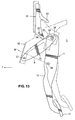
- a conventional structure disclosed in PCT Publication No. WO03/045750 is such that, as shown in FIG. 16 , a fixed pedal support member 100 attached on the side of the dash panel is provided, a pedal axis 102 of a pedal body 101 is arranged in a L-shaped slot 103 of the fixed support member 100, and a rotational lever 105 is attached via an axis 104 in back of the pedal axis 102.
- the pedal axis 102 is held by a holding portion 105a of the rotational lever 105 at the normal state, while at the vehicle frontal collision the rotational lever 105 comes to hit against a vehicle-body side member 106 provided on the side of an instrument panel member and thereby rotates in the direction of an arrow h, so that a pressing portion 105b of the rotational lever 105 presses down the pedal axis 102 along the L-shaped slot 103. Accordingly, the pedal body 101 is rotated around a pivot of an axis 108 of a push rod 107, so that a pedal pad 109 is moved forward as shown by an arrow i in FIG. 16 . Thus, the rearward move of the pedal can be restrained.
- the fixed pedal support member 100 needs a support portion to support the axis 104 because the axis 104 of the rotational lever 105 is positioned in back of the pedal axis 102, there was a problem in that the pedal support structure would not be made properly compact. Further, since the rotational lever 105 rotates, the holding of the pedal axis 102 by the holding portion 105a may be unstable. Therefore, there is a concern that the position of the pedal axis 102 would lower improperly according to some operational manner of the pedal body 101 by the passenger. Thus, there was a problem in that the reliability of the pedal support would deteriorate.
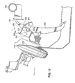
- FIG. 17 Another conventional structure disclosed in Japanese Patent Laid-Open Publication No. 2008-77150 is such that, as shown in FIG. 17 , a fixed pedal support member 201 attached on the side of a dash panel 200 is provided, a pedal axis 203 of a pedal body 202 is pivotally supported at the fixed pedal support member 201, and a rotational lever 205 is attached via an axis 204 in back of the pedal axis 203.
- the pedal axis 203 is held by a projection 201a of the fixed pedal support member 201 and a stopper 208 at the normal state, and at the vehicle frontal collision the rotational lever 205 comes to hit against a vehicle-body side member 207 provided on the side of an instrument panel member 206 and thereby rotates in the direction of an arrow j, so that a pressing portion 205b of the rotational lever 2 05 presses down the pedal axis 203. Accordingly, the pedal axis 203 makes the projection 201 a and the stopper 208 deform, so that the pedal axis 203 drops. Thus, the rearward move of the pedal can be restrained.
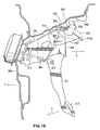
- FIG. 18 Another conventional structure disclosed in Japanese Patent Laid-Open Publication No. 2006-139345 is such that, as shown in FIG. 18 , a bracket 302 is provided at a lower portion of a cowl panel 301, which is a vehicle-body rigidity member which may move rearward only slightly relative to a dash panel 300 at the vehicle frontal collision, and a fixed pedal support member 304 and a swing pedal support member 305 are provided at the bracket 302 via bolt and nut 303 so that they can move rearward at the vehicle collision.
- These members 304, 305 are formed in a gate shape, and the swing pedal support member 30 5 is arranged inside the fixed pedal support member 304.
- a vehicle-body side member 306 is attached to the lower portion of the cowl panel 301, and a wire guide 307 and a plate-shaped projecting member 308 are attached to the fixed pedal support member 304 as a unit.
- a pedal axis 310 is provided at the swing pedal support member 305 via a pivot of a pivot axis 309.
- a pedal body 311 is attached to the pedal axis 310.
- One end of a wire 312 is fixed to the bracket 302. A middle portion of this wire 312 is guided by a guide portion 307a of a wire guide 307, and the other end of the wire 312 is fixed around the pedal axis 310.
- the dash panel 300 moves rearward and thereby the fixed pedal support member 304 and the swing pedal support member 305 are detached from the bracket 302 as shown by an arrow k in FIG. 18 .
- the wire 312 tenses, and the other end of this wire 312 pulls back the pedal axis 310.
- the pedal axis 310 and the swing pedal support member 305 rotate clockwise around the pivot of the pivotal axis 309.
- the pedal body 311 rotates around an axis 314 of a push rod 313 so that a pedal pad 315 moves forward (in the direction of an arrow m ).
- the rearward move of the pedal can be restrained.
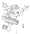
- FIG. 19 a fixed pedal support member 401 attached to a dash panel 400 is provided, a pedal axis 403 of a pedal body 402 is pivotally supported at a lower portion of the fixed pedal support member 401, and a rotational lever 405 is attached to an upper portion of the fixed pedal support member 401 via an axis 404.
- a vehicle-body side member 407 is attached to an instrument panel member 406, and a T-shaped link 408 and a straight-shaped link 409 are arranged between the rotational lever 405 and the pedal body 402. According to this structure shown in FIG.
- the rotational lever 405 comes to hit against a vehicle-body side member 407 and thereby rotates in the direction of an arrow n, so that a lower portion of the rotational lever 405 pushes a rear portion of the T-shaped link 408 and thereby rotate this link 408 downward as shown by an arrow p.
- the T-shaped link 408 pushes down the straight-shaped link 409 as shown by an arrow r.
- an upper rear portion of the pedal body 402 is pressed downward, so that the pedal pad 402 is rotated so that a pedal pad 410 can move forward as shown by an arrow s.
- the rearward move of the pedal can be restrained.
- an arrow F shows the forward direction of the vehicle.
- An object of the present invention is to provide an operational pedal support structure of an automotive vehicle equipped with a means for compulsively moving down the pedal at the vehicle frontal collision, which can be made properly compact and simple having a high reliability.
- an operational pedal support structure of an automotive vehicle which is to be or is arranged in back of a dash panel constituting a front portion of a vehicle compartment, comprising a fixed pedal support member to be provided on the side of the dash panel, a swing pedal support member supported relative to the dash panel and/or the fixed pedal support member so as to swing substantially in a vertical direction around a front portion thereof and extending obliquely upward and rearward in a normal or operational position, a first pivotal axis provided at a rear portion of the swing pedal support member and extending in a direction substantially orthogonal to said swing pedal support member, i.e.
- a pedal body supported at the swing pedal support member via the first pivotal axis so as to swing around the first pivotal axis
- a stopper member preferably a vehicle-body side member, provided in back of and away from the fixed pedal support member at a predetermined position, preferably being fixed to a vehicle body
- a rotational lever provided in front of and away from the vehicle-body side member, the rotational lever being supported at the fixed pedal support member via a second pivotal axis extending substantially in the same direction as the first pivotal axis, preferably substantially in the vehicle width direction, so as to swing in a vehicle longitudinal direction around the second pivotal axis, the rotational lever contacting the stopper member and rotating around the second pivotal axis so as to press down the swing pedal support member downward in case the fixed pedal support member moves rearward, a downward-move restricting means to allow a downward move of the first pivotal axis only in case the rotational lever rotates, and a pressing portion provided at the rotational lever so
- the rotational lever since the rotational lever hits against the stopper member and thereby rotates around the second pivotal axis at the vehicle frontal collision, so that the pressing portion of the rotational lever presses down the swing pedal support member and thereby the downward move of the first pivotal axis (pedal axis) is allowed, the pedal body can be compulsively moved downward and thereby the safety of the passenger can be ensured.
- the pressing portion of the rotational lever presses down the swing pedal support member in front of the second pivotal axis, the operational pedal support structure equipped with the means for compulsively moving down the pedal at the vehicle frontal collision can be made properly compact.
- the simple operational pedal support structure of an automotive vehicle having the high reliability can be provided.
- the rotational lever is arranged in front of and away from stopper member, assembling of an instrument panel module to a vehicle body after the pedal is attached can be improved.
- the swing pedal support member has a receiving portion which is slant or curves substantially in a direction orthogonal to the swing pedal support member, i.e. in the vehicle width direction so as to contact the pressing portion.
- the downward-move restricting means comprises a holding portion which is provided at the rotational lever so as to hold the swing pedal support member in case the rotational lever does not rotate so that the swing pedal support member cannot swing downward, and to release the holding of the swing pedal support member in case the rotational lever rotates so that the downward move of the first pivotal axis can be allowed.
- the swing pedal support member can be surely held by the holding portion at the normal state (the vehicle non-collision).
- this holding is released at the vehicle collision, the downward move of the first pivotal axis can be allowed, so that any erroneous operation may be prevented.
- the holding portion deforms in case a downward load acting on the swing pedal support member is a specified magnitude or greater so as to release said holding of the swing pedal support member.
- said downward-move restricting means restricts the downward move of the first pivotal axis in case a downward load acting on the swing pedal support member is less than a specified magnitude, and allows the downward move of the first pivotal axis in case the downward load is the specified magnitude or greater.
- the downward-move restricting means comprises an opening which opens from a first-pivotal-axis support portion to support the first pivotal axis in a different direction from a direction of an operational load which is applied to the first pivotal axis in case the pedal body is operated, and a restricting portion which is formed between the opening and the first-pivotal-axis support portion and deforms so as to allow the first pivotal axis to pass therethrough in case the downward load acting is the specified magnitude or greater.
- the restriction portion restricts the downward move of the pedal axis as the first pivotal axis in case the downward load acting is smaller than the specified magnitude, the erroneous operation of the pedal dropping at the normal state (the vehicle non-collision) can be prevented surely.
- the restricting portion deforms, by receiving the downward load acting which is the specified magnitude or greater, and allows the first pivotal axis to pass through the first pivotal axis.
- the pedal is moved downward compulsively, so that the rearward move of the pedal can be prevented surely.
- the opening may comprise a slit portion which extends from the first-pivotal-axis support portion more downward than the direction of the operational load which is applied to the first pivotal axis in case the pedal body is operated.
- the second pivotal axis is positioned substantially above the first pivotal axis and substantially at the same location as the first pivotal axis in the vehicle longitudinal direction or in front of the first pivotal axis.
- said opening comprises a slit portion which extends from the first-pivotal-axis support portion more downward than the direction of the operational load which is applied to the first pivotal axis in case the pedal body is operated.
- said pressing portion of the rotational lever contacts a specified portion of said swing pedal support member which is positioned in front of said first pivotal axis in case the rotational lever rotates.
- said stopper member is a vehicle-body side member to be fixed at a predetermined position at a vehicle body.
- a method of providing an operational pedal support structure of an automotive vehicle, to be arranged in back of a dash panel constituting a front portion of a vehicle compartment comprising the steps of:
- said swing pedal support member is provided with a receiving portion which is slant or curves substantially in the vehicle width direction so as to contact said pressing portion.
- said downward-move restricting means is provided with a holding portion arranged at said rotational lever so as to hold said swing pedal support member in case the rotational lever does not rotate so that the swing pedal support member cannot swing downward, and to release said holding of the swing pedal support member in case the rotational lever rotates so that said downward move of the first pivotal axis can be allowed.
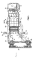
- FIG. 1 is a side view showing an operational pedal support structure of an automotive vehicle according to a first embodiment
- FIG. 2 is a back view of the operational pedal support structure of FIG. 1
- FIG. 3 is a plan view of a major part of FIG. 1
- a dash panel 3 is formed by a dash upper panel 1 (an upper dash-panel) and a dash lower panel 2 (a lower dash-panel) which are joined, which partitions an engine room 4 (a two-kind motor room of a hybrid vehicle) from a vehicle compartment 5 in a vehicle longitudinal direction.
- the dash panel 3 is a panel member which constitutes a front portion of the vehicle compartment 5.
- a masterback or brake booster 6 and a master cylinder 7 of a brake device are arranged at the dash upper panel 1 on the side of the engine room 4.
- a push rod 8 of the brake device extends toward the vehicle compartment 5, and its rear end is connected approximately to a middle portion of a pedal body 12 of a brake pedal 11 as an operational pedal, preferably via a fork 9 and an axis 10.
- a pedal pad 13 as a pedal pressing face is formed at a lower end portion of the pedal body 12.
- An operational pedal support structure of an automotive vehicle is arranged in back of the dash panel 3 which constitutes the front portion of the vehicle compartment 5, that is, on the side of the vehicle compartment 5.
- a dash cross member 14 which extends in a vehicle width direction is attached to a specified portion which corresponds to an upper portion of the masterback 6.
- an instrument panel member 15 which extends in the vehicle width direction and has preferably a closed cross section is provided at a specified portion in the vehicle compartment which corresponds right and left hinge pillars (not illustrated) or front pillars.
- a vehicle-body side member 16 which functions as a bracket for contact is attached to a front portion of the instrument panel member 15.
- the operational pedal support structure of an automotive vehicle preferably comprises a pair of fixed pedal support members 17, 18 (hereinafter, referred to as “mount brackets”), a pair of swing pedal support members 19, 20 (hereinafter, referred to as “swing arms”), the above-described pedal body 11, the above-described vehicle-body side member 16, and a rotational lever 21 which is preferably formed in a gate shape.
- the pedal body 11 is supported at the pair of swing arms 19, 20 via a first pivotal axis 28 (pedal axis) which will be described below.
- the left-side mount bracket 17 includes an upper attachment piece 17a and a lower attachment piece 17b, which are bent integrally, at its front portion. It includes flanges 17c, 17d which face to the left at its upper and lower portions. It further includes a bend piece 17e which faces to the right at its rear portion.
- the right-side mount bracket 18 includes an upper attachment piece 18a and a lower attachment piece 18b, which are bent integrally, at its front portion. It includes a flange 18c which faces to the right at its upper, and includes a flange 18d which faces to the left at its lower portion. It further includes a bend piece 18e which faces to the left at its rear portion.
- the upper attachment pieces 17a, 18a of the mount brackets 17, 18 are attached to the dash cross member 14 with attaching members such as bolts 22 and nuts 23.
- the lower attachment pieces 17b, 18b of the mount brackets 17, 18 are attached to the bracket 26 (attaching bracket) with attaching members such as bolts 24 and nuts 25 as shown in FIGS. 1 through 3 .
- This bracket 26 is an attaching bracket which is provided at the dash panel 3 (specifically, the dash upper panel 1 ) on the side of the vehicle compartment 5 so as to correspond to the center of the masterback 6.
- the right and left mount brackets 17, 18 attached on the side of the dash panel 3 have portions a, b so that each of their rear sides is relatively narrow and each of their front sides is relatively wide as shown in the plan view of FIG. 3 . Thereby, the rigidity of these brackets 17, 18 and the safety of the pedal support are ensured.
- the above-described swing arms 19, 20 are supported so as to swing vertically relative to the dash panel 3 at their front portions and extend obliquely rearward and upward as shown in FIG. 1 .
- the right and left swing arms 19, 20 are pivotally supported at the mount brackets 17, 18 independently via pins 27, 27 (axes extending in the vehicle width direction).
- the swing arms 19, 20 preferably include receiving portions 19a, 20a at their middle portions, respectively. These portions 19a, 20a are formed in a convex shape by bending their middle portions toward the pedal body 12 so as to be contacted by the rotational lever 21. Thereby, the appropriate rigidity of the swing arms 19, 20 can be ensured. Further, the amount of contact face overlapping between the rotational lever 21 and the swing arms 19, 20 can be properly enlarged in case the rotational lever 21 rotates, so that the rotational lever 21 can contact the swing arms 19, 20 surely.
- the pedal body 12 is pivotally supported at rear portions (free end portions) of the swing arms 19, 20 via the pedal axis 28 as the first pivotal axis which extends in the vehicle width direction.
- the above-described pedal stoppers may be joined to the mount brackets, and in this case the stoppers may be joined at a position away from the bolts.
- the above-described vehicle-body side member 16 as the reinforcing member on the side of instrument panel member 15 is fixed in back of and away from the mount brackets 17, 18. More specifically, the vehicle-body side member 16 is fixed in back of and away from the rear portion of the rotational lever 21 as well.
- the rotational lever 21 is not connected to, preferably away from the front portion of the vehicle-body side member 16 as shown in FIGS. 1 and 2 , and supported at the mount brackets 17, 18 via rotational lever axes 33, 33 as the second axis which extend in the vehicle width direction so as to swing in the vehicle longitudinal direction.
- the rotational lever 21 rotates around the rotational lever axes 33, 33 and then presses down the swing arms 19, 20.
- FIG. 5 is an enlarged side view of a major part of FIG. 1 , and as shown in this figure, the rotational lever axes 33, 33 are positioned substantially right above the pedal axis 28.
- the rotational lever 21 preferably includes an upper piece 21a and flanges 21b, 21b which are formed integrally so as to be bent from both sides of the upper piece 21a.
- the right and left flanges 21b, 21b have holding portions 34, 34 at their lower portions.
- the support portions 34, 34 hold the swing arms 19, 20 in case the rotational lever 21 does not rotate (at the vehicle non-collision), and release this holding of the swing arms 19, 20 in case the rotational lever 21 rotates.
- each of the holding portions 34 is, as shown in the enlarged view of FIG. 5 , formed so as to extend straightly along or obliquely inward relative to its rotational locus ⁇ . Thereby, the appropriate engagement between the holding portions 34 and the swing arms 19, 20 at the normal state (the vehicle non-collision) is ensured. As shown in FIG.
- the holding portion 34 is provided at the same longitudinal position as the rotational lever axis 33 which is as the second pivotal axis of the rotational lever 21 or in back of the rotational lever axis 33 (the present embodiment) so as to hold the swing arms 19, 20 in case the rotational lever 21 does not rotate and not to hold the swing arms 19, 20, i.e., to release the holding of the swing arms 19, 20 in case the rotational lever 21 rotates (see FIGS. 7 through 10 ).
- the lower portion of the upper piece 21a of the rotational lever 21 functions as a pressing portion 35.
- the pressing portion 35 presses down the receiving portions 19a, 20a of the swing arms 19, 20 so that the swing arms 19, 20 can be moved downward in case the rotational lever 21 rotates.
- the pressing portion 35 is positioned in front of and below the rotational lever axis 33.
- a downward-move restricting means (see the above-described holding portions 34 and/or slit portions 37 and restricting portions 38, which will be described below) to restrict the downward move of the pedal axis 28 as the first pivotal axis is provided at the mount brackets 17, 18 and/or the rotational lever 21.
- This downward-move restricting means comprises the slit portions 37 which extend downward from the first-pivotal-axis support portions 36 to support the pedal axis 28 in a different direction from the direction of an operational load which is applied to the pedal axis 28 in case the pedal body 12 is operated, and the restricting portions 38 which are formed between the slit portions 37 and the first-pivotal-axis support portions 36 and deform so as to allow the pedal axis 28 to pass therethrough in case a downward load acting on the pedal axis 28 is the specified magnitude or greater.
- the above-described direction of the operational load almost matches the locus of an arc shape with its center at the axis 10 in case the pedal is pressed the most.
- the mount brackets 17, 18 are configured to restrict the downward move of the pedal axis 28 for the input load smaller than the specified magnitude, and allow the downward move of the pedal axis 28 for the input load of the specified magnitude or greater.
- the restricting portions 38 have a shape extending substantially toward the holding portion 34. That is, the downward-move restricting means which comprises the above-described holding portions 34 and/or the slit portions 37 and the restricting portions 38 is the means for allowing the pedal axis 28 as the first pivotal axis to be compulsively moved downward only in case the rotational lever 21 rotates.
- engaging convex portions 19b, 20b are formed at rear portions (free end lower portions) of the swing arms 19, 20 so as to face to holding portions 34, 34.
- This gap g functions to prevent any noise from occurring during the vehicle traveling.
- the pedal axis 28 is supported at the first-pivotal-axis support portions 36 and the restricting portions 38 of the mount brackets 17, 18.
- the relatively large force acts on the pedal axis 28 compared to the normal braking operation, so that the above-described gap g vanishes. Therefore, the pedal axis 28 is held by both of the restring portions 38 and the holding portions 34 at the panic braking.
- the engaging convex portions 19b, 20b and the holding portions 34 are arranged between the spacers 30 and the mount brackets 17, 18 and thereby positioned properly.
- the upper portion of the pedal body 12 and the rotational lever 21 are configured to overlap with each other in the vehicle vertical direction, so that the vertical dimension of the operational pedal support structure is made properly compact.
- the pedal axis 28 and the rotational lever axes 33 are arranged closely and the rigidity of the portion at the rotational lever axes 33 is increased by the spacers 30, so that the relative position of the rotational lever axes 33 to the pedal axis 28 changes so little that the stable move of the rotational lever 21 can be ensured.
- the swing arms 19, 20 and the rotational lever 21 are supported at the mount brackets 17, 18 respectively and separately. Thereby, the concave space between the swing arms 19, 20 and below the rotational lever 21 can be utilized, and the stable move (rotational operation) can be obtained at the vehicle frontal collision even if these elements 19, 20, 21 are distorted.
- mount brackets 17, 18 and the swing arms 19, 20 are respectively made of a plate member, and as shown in FIGS. 2 and 3 , these members 17 - 20 are formed in the curve shape described above, respectively. Accordingly, both the increase of rigidity of these members 17 - 20 and the light weight are achieved.
- the rotational lever 21 in the non-rotation state is away from the swing arms 19, 20 as well as from the vehicle-body side member 16 as shown in FIG. 5 .
- the rotational lever 21 is formed in the gate shape
- the swing arm are comprised of the pair of swing arms 19, 20 which are formed so as to project inward
- the rotational member 21 and the swing arms 19, 20 are formed in the shape along side walls of the mount brackets 17, 18.
- the pressing portion 35 of the rotational lever 21 projects substantially downward and forward from the rotational lever axes 33 as the second pivotal axis. Thereby, the pressing portion 35 is pushed rearward by the dash panel 3 at the vehicle collision, so that the rotation of the rotational lever 21 is promoted.
- the flanges 21b, 21b of the rotational levers 21 and the swing arms 19, 20 may be arranged between the mount brackets 17, 18 and the spacers 30, 30 so that the holding portions 34 can hold the engaging convex portions 19b, 29b of the swing arms 19, 20 more surely at the panic braking.
- the thickness of the swing arms 19, 20 can be made thinner, and the move of the rotational lever 21 at the normal state can be made difficult by the fastening structure with the bolt 29 and nut 32.
- the flanges 21b, 21b of the rotational levers 21 may not be arranged between the mount brackets 17, 18 and the spacers 30, 30 in order to give priority to the fastening safety with the bolt 29 and nut 32.
- reference numeral 30 denotes a foot-brake lamp switch contact portion which provided at the pedal body 12 via a bracket 40
- reference numeral 41 denotes a foot-brake lamp switch which is attached to a lower portion of the pedal stopper 31
- an arrow F denotes the forward direction of the vehicle.
- FIG. 6 is a side view of the operational pedal support structure at the normal state (vehicle non-collision).
- an extension line ⁇ of a longitudinal direction of the swing arm 19 is set so as to pass near a front end 8F of the push rod 8, so that the downward move of the push rod 8 at the vehicle collision can be promoted.
- the operational pedal support structure of an automotive vehicle which is arranged in back of the dash panel 3 constituting the front portion of the vehicle compartment 5, preferably comprises the fixed pedal support member (see the mount brackets 17, 18) provided on the side of the dash panel 3, the swing pedal support member (see the swing arms 19, 20) supported relative to the dash panel 3 so as to swing in the vertical direction around its front portion and extending obliquely upward and rearward, the first pivotal axis (see the pedal axis 28) provided at the rear portions of the swing pedal support member (swing arms 19, 20) and extending substantially in the vehicle width direction, the pedal body 12 supported at the swing pedal support member (see the swing arms 19, 20) via the first pivotal axis (pedal axis 28) so as to swing around the first pivotal axis (pedal axis 28), the vehicle-body side member 16 provided in back of and away from the fixed pedal support member (mount brackets 17, 18) and fixed to the vehicle body
- the rotational lever 21 since the rotational lever 21 hits against the vehicle-body side member 16 and thereby rotates around the second pivotal axis (rotational lever axes 33) at the vehicle frontal collision, so that the pressing portion 35 of the rotational lever 21 presses down the swing pedal support member (swing arms 19, 20) and thereby the downward move of the first pivotal axis (pedal axis 28) is allowed, the pedal body 12 can be compulsively moved downward and thereby the safety of the passenger can be ensured.
- the operational pedal support structure equipped with the means for compulsively moving down the pedal 11 (the pedal compulsive downward-move means) at the vehicle frontal collision can be made properly compact.
- the downward move of the pedal axis 28 as the first pivotal axis is allowed only in case the rotational lever 21 rotates, the simple operational pedal support structure of an automotive vehicle with the high reliability can be provided.
- the rotational lever 21 is arranged in front of and away from the vehicle-body side member 16, assembling of an instrument panel module (not illustrated) to the vehicle body after the pedal 11 is attached can be improved.
- the pressing portion 35 of the rotational lever 21 presses down the swing pedal support member (swing arms 19, 20) and thereby the first pivotal axis (pedal axis 28) is moved downward
- the rear portion of the swing pedal support member (swing arms 19, 20) rotates in the arc shape around its front portion and the middle portion of the pedal body 12 is pivotally connected to the rear end of the push rod 8, the pedal axis 28 as the first pivotal axis is moved downward and the pedal pad 13 (pedal pressing portion) moves obliquely forward and downward at the vehicle collision. Consequently, the sufficient amount of rearward-move prevention can be ensured.
- the swing pedal support member (see the swing arms 19, 20) has the receiving portions 19a, 20a which are slant or curved substantially in the vehicle width direction so as to contact the pressing portion 35 (see FIGS. 2 and 3 ).
- the contact of the pressing portion 35 of the rotational lever 21 and the receiving portions 19a, 20a of the swing pedal support member (swing arms 19, 20) can be obtained surely, so that the compulsive downward move of the first pivotal axis (pedal axis 28) and the pedal body 12 at the vehicle collision can be obtained surely.
- the above-described downward-move restricting means comprises the holding portion 34 which is provided at the rotational lever 21 so as to hold the swing pedal support member (swing arms 19, 20) in case the rotational lever 21 does not rotate, and to release the holding of the swing pedal support member (swing arms 19, 20) in case the rotational lever 21 rotates (see FIGS. 4 and 5 ).
- the swing pedal support member (swing arms 19, 20) can be surely held by the holding portion 34 at the normal state (the vehicle non-collision).
- this holding is released at the vehicle collision, the downward move of the pedal axis 28 as the first pivotal axis can be allowed, so that any erroneous operation can be prevented.
- the above-described downward-move restricting means comprises the slit portion 37 as the opening which extends downward from the first-pivotal-axis support portion 36 to support the first pivotal axis (pedal axis 28) in the different direction from the direction of the operational load which is applied to the first pivotal axis (pedal axis 28) in case the pedal body 12 is operated, and the restricting portion 38 which is formed between the slit portion 37 (opening) and the first-pivotal-axis support portion 36 and breaks or deforms so as to allow the first pivotal axis (pedal axis 28) to pass through them in case the downward load acting on the swing pedal support member (swing arms 19, 20), i.e., the first pivotal axis (pedal axis 28), is the specified magnitude or greater (see FIG.
- the restriction portion 38 restricts the downward move of the pedal axis 38 as the first pivotal axis in case the above-described downward load is smaller than the specified magnitude, the erroneous operation of the pedal 11 dropping at the normal state (the vehicle non-collision) can be prevented surely.
- the restricting portion 38 breaks or deforms, by receiving the downward load which is the specified magnitude or greater, and allows the first pivotal axis (pedal axis 28) to pass through the first pivotal axis (pedal axis 28).
- the pedal 11 is moved downward compulsively, so that the rearward move of the pedal 11 can be prevented surely.
- the above-described downward-move restricting means restricts the downward move of the first pivotal axis (pedal axis 28) in case the downward load is less than the specified magnitude, and allows the downward move of the first pivotal axis (pedal axis 28) in case the downward load is the specified magnitude or greater (see FIGS. 1 , 4 and 5 ).
- FIGS. 11 through 15 show an operational pedal support structure of an automotive vehicle according to another embodiment.
- the operational pedal support structure of an automotive vehicle of the present embodiment is arranged in back of the dash panel 3 (see the previous figures) which constitutes the front portion of the vehicle compartment 5.
- the operational pedal support structure of the present embodiment comprises a mount bracket 50 as the fixed pedal support member which is provided on the side of the dash panel 3, a swing arm 51 as the swing arm pedal support member which is supported relative to the mount bracket 50 so as to swing in the vertical direction around a pin 27 provided at its front portion and extends obliquely upward and rearward, the pedal body 12 which is supported via the pedal axis 28 as the first pivotal axis, which is arranged at a rear portion of the swing arm 51 and extends in the vehicle width direction, so as to swing around the pedal axis 28, and a rotational lever 52 which is supported at the mount bracket 50 via the rotational lever axis 33 which is positioned in front of the pedal axis 28.
- the rotational lever 52 is arranged in front of the vehicle-body side member 16 (see the previous figures) so as not to be connected to this member 16, and supported at the mount bracket 50 via the rotational lever axis 33 which extends substantially in the vehicle width direction so as to swing substantially in the vehicle longitudinal direction. Further, in case the mount bracket 50 retreats relative to the mount bracket 50, the above-described rotational lever 50 hits against the vehicle-body side member 16, and thereby this lever 52 rotates around the rotational lever axis 33 so as to presses down the swing arm 51.
- the above-described rotational lever axis 33 is arranged slightly above and in front of the pedal axis 28.
- the above-described rotational lever 52 has a holding portion 53 which holds the swing arm 51 in case the rotational lever 52 does not rotate and releases this holding of the swing arm 51 in case the rotational lever 21 rotates.
- the rotational lever 52 has a pressing portion 54 which is positioned in front of the rotational lever axis 33 and presses down the swing arm 51.
- the holding portion 53 is configured to elastically deform or plastically deform in case the swing arm 51 is moved down compulsively.
- the swing arm 51 is formed in a slender oval shape or approximately an elliptical shape, and contacts the rotational lever 52 at two points P1, P2 as shown in FIG. 11 . That is, a front face of the holding portion 53 of the rotational lever 52 and a lower face of the pressing portion 54 contact the swing arm 51, so that the rotational lever 52 can hold the swing arm 51. Thereby, the position of the pedal axis 28 as the first pivotal axis at the normal state (vehicle non-collision) can be held.
- the above-descried mount bracket 50 has a first-pivotal-axis support portion 55 to support the pedal axis 28 and a slot portion 56 which connects to the first-pivotal-axis support portion 55 as shown in FIG. 12 .
- the forming direction y of the slot portion 56 extends substantially downward, having some angles relative to the direction of the operational load (the direction of the arrow x in FIG. 12 ) applied to the pedal axis 28 in case the pedal body 12 is operated.
- the holding face (front face) of the holding portion 53 of the rotational lever 52 is slant downward and forward relative to the peripheral direction of the rotational locus Q of the rotational lever 52 so that the rotational lever 52 can be biased toward the holding direction in case the swing arm 51 swings downward.
- the above-described pressing portion 54 is formed in front of and below the rotational lever axis 33 supporting the rotational lever 52 so that the pressing portion 54 can press down the swing arm 51.
- the holding portion 53 constitutes the downward-move restricting means to allow the downward move of the pedal axis 28 only in case the rotational lever 52 rotates.
- FIGS. 11 and 13 are side views showing the state in which the brake pedal 11 is not operated (pressed).
- the power train in the engine room 4 is pushed rearward, and then the dash panel 3 (see the previous figures) retreats.
- the rear portion of the rotational lever 21 hits against the vehicle-body side member 16 (see the previous figures), and the rotational lever 52 rotates counterclockwise around the rotational lever axis 33 as shown in FIG. 13 .
- the swing arm 51 compulsively presses down the swing arm 51 with the pressing portion 54, releasing the holding of the swing arm 51 by the holding portion 53.
- the pedal axis 28 as the first pivotal axis which is provided at a free end portion of the swing arm 51 moves downward along the slot portion 56 of the mount bracket 50, so that the pedal body 12 rotates around the axis 10 of the push rod 8 so that its upper end moves rearward and the pedal pad 13 moves forward. Thereby, the rearward move of the brake pedal 11 can be prevented.
- the dash panel 3 moving rearward at the vehicle collision pushes rearward the pressing portion 54 of the rotational lever 52, so that the pressing portion 54 rotates the swing arm 51 further downward surely. Accordingly, the rearward move of the brake pedal 11 can be prevented more surely.
- FIGS. 14 and 15 are side views showing the state in which the brake pedal is pressed the most. At the vehicle frontal collision, the state changes from FIG. 14 to FIG. 15 , so that the rearward move of the brake pedal 11 can be prevented.
- the operations according to the change of the state from FIG. 14 to FIG. 15 are substantially the same as that from FIG. 11 to FIG. 14 described above, so the same portions are denoted by the same reference characters and their specific descriptions are omitted here.
- the operational pedal support structure of an automotive vehicle which is arranged in back of the dash panel 3 (see the previous figures) constituting the front portion of the vehicle compartment 5, preferably comprises the fixed pedal support member (see the mount bracket 50) provided on the side of the dash panel 3, the swing pedal support member (see the swing arm 51) supported relative to the dash panel 3 so as to swing substantially in the vertical direction around their front portions and extending obliquely upward and rearward, the first pivotal axis (see the pedal axis 28) provided at the rear portions of the swing pedal support member (swing arm 51) and extending substantially in the vehicle width direction, the pedal body 12 supported at the swing pedal support member (swing arm 51) via the first pivotal axis (pedal axis 28) so as to swing around the first pivotal axis (pedal axis 28), the vehicle-body side member 16 (see the previous figures) provided in back of and away from the fixed pedal support member (mount bracket 50) and
- the rotational lever 52 since the rotational lever 52 hits against the vehicle-body side member 16 and thereby rotates around the second pivotal axis (rotational lever axis 33) at the vehicle frontal collision, so that the pressing portion 54 of the rotational lever 52 presses down the swing pedal support member (swing arm 51) and thereby the downward move of the first pivotal axis (pedal axis 28) is allowed, the pedal body 12 can be compulsively moved downward and thereby the safety of the passenger can be ensured.
- the operational pedal support structure equipped with the means for compulsively moving down the pedal 11 (the pedal compulsive downward-move means) at the vehicle frontal collision can be made properly compact.
- the downward move of the pedal axis 28 as the first pivotal axis is allowed only in case the rotational lever 52 rotates, the simple operational pedal support structure of an automotive vehicle with the high reliability can be provided.
- the rotational lever 52 is arranged in front of and away from the vehicle-body side member 16, assembling of an instrument panel module to the vehicle body after the pedal 11 is attached can be improved.
- the pressing portion 54 of the rotational lever 52 presses down the swing pedal support member (swing arm 51) and thereby the first pivotal axis (pedal axis 28) is moved downward
- the rear portion of the swing pedal support member (swing arm 51) rotates in the arc shape around its front portion and the middle portion of the pedal body 12 is pivotally connected to the rear end of the push rod 8, the pedal axis 28 as the first pivotal axis is moved downward and the pedal pad 13 (pedal pressing portion) moves obliquely forward and downward at the vehicle collision. Consequently, the sufficient amount of rearward-move prevention can be ensured.
- FIGS. 11 through 15 The other structures, operations and effects of the second embodiment shown in FIGS. 11 through 15 are substantially the same as those of the first embodiment, so that the same portions are denoted by the same reference characters and their specific descriptions are omitted here.
Landscapes
- Engineering & Computer Science (AREA)
- Mechanical Engineering (AREA)
- Transportation (AREA)
- Physics & Mathematics (AREA)
- General Physics & Mathematics (AREA)
- Automation & Control Theory (AREA)
- Mechanical Control Devices (AREA)
- Braking Elements And Transmission Devices (AREA)
Abstract
Description
- The present invention relates to an operational pedal support structure of an automotive vehicle which can restrain a rearward move of a pedal pressing face (so-called pedal pad) of an operational pedal provided in back of a dash panel at a vehicle frontal collision.
- In general, when the automotive vehicle has a frontal collision, a power train, such as an engine, (or an engine and a motor of a hybrid vehicle) provided in front of the dash panel moves rearward. Accordingly, a masterback or brake booster and the dash panel are pushed rearward, resulting in the rearward move of the operational pedal. Some inventions regarding the operational pedal support structure of an automotive vehicle which can provide a so-called rearward move restraint mechanism to restrain the rearward move of the operational pedal for ensuring the safety of a passenger have been made (see the following patent documents).
- A conventional structure disclosed in
PCT Publication No. WO03/045750 FIG. 16 , a fixedpedal support member 100 attached on the side of the dash panel is provided, apedal axis 102 of apedal body 101 is arranged in a L-shaped slot 103 of thefixed support member 100, and arotational lever 105 is attached via anaxis 104 in back of thepedal axis 102. Herein, thepedal axis 102 is held by aholding portion 105a of therotational lever 105 at the normal state, while at the vehicle frontal collision therotational lever 105 comes to hit against a vehicle-body side member 106 provided on the side of an instrument panel member and thereby rotates in the direction of an arrow h, so that apressing portion 105b of therotational lever 105 presses down thepedal axis 102 along the L-shaped slot 103. Accordingly, thepedal body 101 is rotated around a pivot of anaxis 108 of apush rod 107, so that apedal pad 109 is moved forward as shown by an arrow i inFIG. 16 . Thus, the rearward move of the pedal can be restrained. - According to the above-described conventional structure, however, since the fixed
pedal support member 100 needs a support portion to support theaxis 104 because theaxis 104 of therotational lever 105 is positioned in back of thepedal axis 102, there was a problem in that the pedal support structure would not be made properly compact. Further, since therotational lever 105 rotates, the holding of thepedal axis 102 by theholding portion 105a may be unstable. Therefore, there is a concern that the position of thepedal axis 102 would lower improperly according to some operational manner of thepedal body 101 by the passenger. Thus, there was a problem in that the reliability of the pedal support would deteriorate. - Another conventional structure disclosed in Japanese Patent Laid-Open Publication No.
2008-77150 FIG. 17 , a fixedpedal support member 201 attached on the side of adash panel 200 is provided, apedal axis 203 of apedal body 202 is pivotally supported at the fixedpedal support member 201, and arotational lever 205 is attached via anaxis 204 in back of thepedal axis 203. Herein, thepedal axis 203 is held by aprojection 201a of the fixedpedal support member 201 and astopper 208 at the normal state, and at the vehicle frontal collision therotational lever 205 comes to hit against a vehicle-body side member 207 provided on the side of aninstrument panel member 206 and thereby rotates in the direction of an arrow j, so that a pressing portion 205b of therotational lever 205 presses down thepedal axis 203. Accordingly, thepedal axis 203 makes theprojection 201 a and thestopper 208 deform, so that thepedal axis 203 drops. Thus, the rearward move of the pedal can be restrained. - According to the above-described conventional structure, however, since the fixed
pedal support member 201 needs a support portion to support theaxis 204 because theaxis 204 of therotational lever 205 is positioned in back of thepedal axis 203, there was a problem in that the pedal support structure would not be made properly compact as well. Further, thestopper 208 was necessary additionally. - Another conventional structure disclosed in Japanese Patent Laid-Open Publication No.
2006-139345 FIG. 18 , abracket 302 is provided at a lower portion of acowl panel 301, which is a vehicle-body rigidity member which may move rearward only slightly relative to adash panel 300 at the vehicle frontal collision, and a fixedpedal support member 304 and a swingpedal support member 305 are provided at thebracket 302 via bolt andnut 303 so that they can move rearward at the vehicle collision. Thesemembers pedal support member 305 is arranged inside the fixedpedal support member 304. Further, a vehicle-body side member 306 is attached to the lower portion of thecowl panel 301, and awire guide 307 and a plate-shaped projecting member 308 are attached to the fixedpedal support member 304 as a unit. Moreover, apedal axis 310 is provided at the swingpedal support member 305 via a pivot of apivot axis 309. Apedal body 311 is attached to thepedal axis 310. One end of awire 312 is fixed to thebracket 302. A middle portion of thiswire 312 is guided by aguide portion 307a of awire guide 307, and the other end of thewire 312 is fixed around thepedal axis 310. When the automotive vehicle has the frontal collision, thedash panel 300 moves rearward and thereby the fixedpedal support member 304 and the swingpedal support member 305 are detached from thebracket 302 as shown by an arrow k inFIG. 18 . Then, thewire 312 tenses, and the other end of thiswire 312 pulls back thepedal axis 310. Accordingly, thepedal axis 310 and the swingpedal support member 305 rotate clockwise around the pivot of thepivotal axis 309. Thereby, thepedal body 311 rotates around anaxis 314 of apush rod 313 so that apedal pad 315 moves forward (in the direction of an arrow m). Thus, the rearward move of the pedal can be restrained. - According to the above-described conventional structure, however, since the mechanism to compulsively move the
pedal body 311 obliquely forward and downward by pulling out the swingpedal support member 305 at the vehicle frontal collision exists in back of thepedal axis 310, there was a problem in that the pedal support structure would not be made properly compact. - Further another conventional structure disclosed in
US Patent Application Publication No. 2006/0162481 is such that, as shown inFIG. 19 , a fixedpedal support member 401 attached to adash panel 400 is provided, apedal axis 403 of apedal body 402 is pivotally supported at a lower portion of the fixedpedal support member 401, and arotational lever 405 is attached to an upper portion of the fixedpedal support member 401 via anaxis 404. Further, a vehicle-body side member 407 is attached to aninstrument panel member 406, and a T-shaped link 408 and a straight-shaped link 409 are arranged between therotational lever 405 and thepedal body 402. According to this structure shown inFIG. 19 , at the vehicle frontal collision therotational lever 405 comes to hit against a vehicle-body side member 407 and thereby rotates in the direction of an arrow n, so that a lower portion of therotational lever 405 pushes a rear portion of the T-shaped link 408 and thereby rotate thislink 408 downward as shown by an arrow p. The T-shaped link 408 pushes down the straight-shaped link 409 as shown by an arrow r. Thereby, an upper rear portion of thepedal body 402 is pressed downward, so that thepedal pad 402 is rotated so that apedal pad 410 can move forward as shown by an arrow s. Thus, the rearward move of the pedal can be restrained. - According to the above-described conventional structure, since the
axis 404 of therotational lever 405 exits in front of thepedal axis 403, the rearward move of therotational lever 405 may be ensured, but its downward move may not be ensured. Therefore, the twolinks pedal body 402 exists in back of thepedal axis 403, the pedal support structure would not be made properly compact. Further, since at the vehicle collision the position of thepedal axis 403 may be constant and the pedal may not drop despite the forward move of thepedal pad 410, there was another problem in that any lower space would not be utilized effectively. Moreover, since any proper movement may not be obtained in case thelinks - In
FIGS. 16 -19 , an arrow F shows the forward direction of the vehicle. - An object of the present invention is to provide an operational pedal support structure of an automotive vehicle equipped with a means for compulsively moving down the pedal at the vehicle frontal collision, which can be made properly compact and simple having a high reliability.
- The object is solved by the operational pedal support structure of an automotive vehicle according to the present invention of the independent claim. Preferred embodiments of the present invention are subject of the dependent claims.
- According to the present invention, there is provided an operational pedal support structure of an automotive vehicle, which is to be or is arranged in back of a dash panel constituting a front portion of a vehicle compartment, comprising a fixed pedal support member to be provided on the side of the dash panel, a swing pedal support member supported relative to the dash panel and/or the fixed pedal support member so as to swing substantially in a vertical direction around a front portion thereof and extending obliquely upward and rearward in a normal or operational position, a first pivotal axis provided at a rear portion of the swing pedal support member and extending in a direction substantially orthogonal to said swing pedal support member, i.e. in a vehicle width direction, a pedal body supported at the swing pedal support member via the first pivotal axis so as to swing around the first pivotal axis, a stopper member, preferably a vehicle-body side member, provided in back of and away from the fixed pedal support member at a predetermined position, preferably being fixed to a vehicle body, a rotational lever provided in front of and away from the vehicle-body side member, the rotational lever being supported at the fixed pedal support member via a second pivotal axis extending substantially in the same direction as the first pivotal axis, preferably substantially in the vehicle width direction, so as to swing in a vehicle longitudinal direction around the second pivotal axis, the rotational lever contacting the stopper member and rotating around the second pivotal axis so as to press down the swing pedal support member downward in case the fixed pedal support member moves rearward, a downward-move restricting means to allow a downward move of the first pivotal axis only in case the rotational lever rotates, and a pressing portion provided at the rotational lever so as to press down the swing pedal support member, the pressing portion being positioned substantially in front of the second pivotal axis.
- According to the present invention, since the rotational lever hits against the stopper member and thereby rotates around the second pivotal axis at the vehicle frontal collision, so that the pressing portion of the rotational lever presses down the swing pedal support member and thereby the downward move of the first pivotal axis (pedal axis) is allowed, the pedal body can be compulsively moved downward and thereby the safety of the passenger can be ensured. Thus, since the pressing portion of the rotational lever presses down the swing pedal support member in front of the second pivotal axis, the operational pedal support structure equipped with the means for compulsively moving down the pedal at the vehicle frontal collision can be made properly compact. Further, since the downward move of the pedal axis as the first pivotal axis is allowed only in case the rotational lever rotates, the simple operational pedal support structure of an automotive vehicle having the high reliability can be provided. Moreover, since the rotational lever is arranged in front of and away from stopper member, assembling of an instrument panel module to a vehicle body after the pedal is attached can be improved. In addition, since in case the pressing portion of the rotational lever presses down the swing pedal support member and thereby the first pivotal axis is moved downward, the rear portion of the swing pedal support member rotates in an arc shape around its front portion and the middle portion of the pedal body is pivotally connected to the rear end of the push rod, the pedal axis as the first pivotal axis is moved downward and the pedal pad (pedal pressing face) moves obliquely forward and downward at the vehicle collision. Consequently, the sufficient amount of rearward-move prevention can be ensured.
- According to an embodiment of the present invention, the swing pedal support member has a receiving portion which is slant or curves substantially in a direction orthogonal to the swing pedal support member, i.e. in the vehicle width direction so as to contact the pressing portion. Thereby, the contact of the pressing portion of the rotational lever and the receiving portion of the swing pedal support member can be obtained surely, so that the compulsive downward move of the first pivotal axis and the pedal body at the vehicle collision can be obtained surely.
- According to another embodiment of the present invention, the downward-move restricting means comprises a holding portion which is provided at the rotational lever so as to hold the swing pedal support member in case the rotational lever does not rotate so that the swing pedal support member cannot swing downward, and to release the holding of the swing pedal support member in case the rotational lever rotates so that the downward move of the first pivotal axis can be allowed. Thereby, the swing pedal support member can be surely held by the holding portion at the normal state (the vehicle non-collision). Further, since this holding is released at the vehicle collision, the downward move of the first pivotal axis can be allowed, so that any erroneous operation may be prevented.
- Preferably, the holding portion deforms in case a downward load acting on the swing pedal support member is a specified magnitude or greater so as to release said holding of the swing pedal support member.
- Further preferred, said downward-move restricting means restricts the downward move of the first pivotal axis in case a downward load acting on the swing pedal support member is less than a specified magnitude, and allows the downward move of the first pivotal axis in case the downward load is the specified magnitude or greater.
- According to another embodiment of the present invention, the downward-move restricting means comprises an opening which opens from a first-pivotal-axis support portion to support the first pivotal axis in a different direction from a direction of an operational load which is applied to the first pivotal axis in case the pedal body is operated, and a restricting portion which is formed between the opening and the first-pivotal-axis support portion and deforms so as to allow the first pivotal axis to pass therethrough in case the downward load acting is the specified magnitude or greater. Thereby, since the restriction portion restricts the downward move of the pedal axis as the first pivotal axis in case the downward load acting is smaller than the specified magnitude, the erroneous operation of the pedal dropping at the normal state (the vehicle non-collision) can be prevented surely. Meanwhile, at the vehicle frontal collision the restricting portion deforms, by receiving the downward load acting which is the specified magnitude or greater, and allows the first pivotal axis to pass through the first pivotal axis. Thus, the pedal is moved downward compulsively, so that the rearward move of the pedal can be prevented surely. Herein, the opening may comprise a slit portion which extends from the first-pivotal-axis support portion more downward than the direction of the operational load which is applied to the first pivotal axis in case the pedal body is operated.
- According to another embodiment of the present invention, the second pivotal axis is positioned substantially above the first pivotal axis and substantially at the same location as the first pivotal axis in the vehicle longitudinal direction or in front of the first pivotal axis. Thereby, the longitudinal dimension of the pedal support structure (especially, the fixed pedal support member) can be properly shortened.
- Preferably, said opening comprises a slit portion which extends from the first-pivotal-axis support portion more downward than the direction of the operational load which is applied to the first pivotal axis in case the pedal body is operated.
- Further preferred, said pressing portion of the rotational lever contacts a specified portion of said swing pedal support member which is positioned in front of said first pivotal axis in case the rotational lever rotates.
- Preferably, said stopper member is a vehicle-body side member to be fixed at a predetermined position at a vehicle body.
- According to a further aspect, there is provided a method of providing an operational pedal support structure of an automotive vehicle, to be arranged in back of a dash panel constituting a front portion of a vehicle compartment, comprising the steps of:
- providing a fixed pedal support member to be mounted on the side of the dash panel;
- supporting a swing pedal support member relative to the fixed pedal support member so as to swing substantially in a vertical direction around a front portion thereof and extending obliquely upward and rearward;
- providing a first pivotal axis at a rear portion of the swing pedal support member so as to extend in a direction substantially orthogonal to said swing pedal support member so as to extend in a vehicle width direction when the operational pedal support structure is mounted on the dash panel of the vehicle;
- supporting a pedal body at the swing pedal support member via the first pivotal axis so as to swing around the first pivotal axis;
- providing a stopper member in back of and away from the fixed pedal support member at a predetermined position;
- providing a rotational lever in front of and away from the stopper member, the rotational lever being supported at the fixed pedal support member via a second pivotal axis extending substantially in the same direction as the first pivotal axis so as to swing substantially in a vehicle longitudinal direction around the second pivotal axis, the rotational lever contacting the stopper member and rotating around the second pivotal axis so as to press down the swing pedal support member downward in case the fixed pedal support member moves rearward;
- providing a downward-move restricting means to allow a downward move of the first pivotal axis only in case the rotational lever rotates; and
- providing a pressing portion at the rotational lever so as to press down the swing pedal support member, the pressing portion being positioned substantially in front of the second pivotal axis.
- Preferably, said swing pedal support member is provided with a receiving portion which is slant or curves substantially in the vehicle width direction so as to contact said pressing portion.
- Further preferred, said downward-move restricting means is provided with a holding portion arranged at said rotational lever so as to hold said swing pedal support member in case the rotational lever does not rotate so that the swing pedal support member cannot swing downward, and to release said holding of the swing pedal support member in case the rotational lever rotates so that said downward move of the first pivotal axis can be allowed.
- Other features, aspects, and advantages of the present invention will become apparent from the following description which refers to the accompanying drawings.
-
FIG. 1 is a side view showing an operational pedal support structure of an automotive vehicle according to a first embodiment of the present invention. -
FIG. 2 is a back view of the operational pedal support structure ofFIG. 1 , when viewed from the inside of a vehicle. -
FIG. 3 is a plan view of a major part ofFIG. 1 . -
FIG. 4 is an exploded perspective view of the operational pedal support structure. -
FIG. 5 is an enlarged side view of a major part ofFIG. 1 . -
FIG. 6 is a side view of the operational pedal support structure at a vehicle non-collision. -
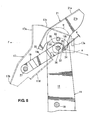
FIG. 7 is a side view showing a case in which a holding portion retreats. -
FIG. 8 is a side view showing a case in which a first pivotal axis is released. -
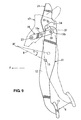
FIG. 9 is a side view showing a case of a pedal compulsive downward-move caused by a rotational lever. -
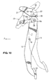
FIG. 10 is a side view showing a case in which a pressing portion of the rotational lever presses down an upper end portion of a pedal body. -
FIG. 11 is a side view showing an operational pedal support structure of an automotive vehicle according to a second embodiment. -
FIG. 12 is an enlarged side view of a fixed pedal support member ofFIG. 11 . -
FIG. 13 is a side view showing a case of the pedal compulsive downward-move. -
FIG. 14 is a side view showing a state of vehicle non-collision in case the pedal has been pressed the most. -
FIG. 15 is a side view showing a pedal compulsive downward-move in case the pedal has been pressed the most. -
FIG. 16 is a side view showing an operational pedal support structure of an automotive vehicle according to a conventional structure. -
FIG. 17 is a side view showing an operational pedal support structure of an automotive vehicle according to another conventional structure. -
FIG. 18 is a side view showing an operational pedal support structure of an automotive vehicle according to further another conventional structure. -
FIG. 19 is a side view showing an operational pedal support structure of an automotive vehicle according to further another conventional structure. - Hereinafter, preferred embodiments of the present invention will be described referring to the accompanying drawings. Although the embodiments are described separately, it should be understood that single feature(s) of one embodiment may be combined with the other embodiment and vice versa.
-
FIG. 1 is a side view showing an operational pedal support structure of an automotive vehicle according to a first embodiment,FIG. 2 is a back view of the operational pedal support structure ofFIG. 1 , andFIG. 3 is a plan view of a major part ofFIG. 1 . InFIG. 1 , adash panel 3 is formed by a dash upper panel 1 (an upper dash-panel) and a dash lower panel 2 (a lower dash-panel) which are joined, which partitions an engine room 4 (a two-kind motor room of a hybrid vehicle) from avehicle compartment 5 in a vehicle longitudinal direction. Herein, thedash panel 3 is a panel member which constitutes a front portion of thevehicle compartment 5. A masterback orbrake booster 6 and amaster cylinder 7 of a brake device are arranged at the dash upper panel 1 on the side of theengine room 4. - A
push rod 8 of the brake device extends toward thevehicle compartment 5, and its rear end is connected approximately to a middle portion of apedal body 12 of abrake pedal 11 as an operational pedal, preferably via afork 9 and anaxis 10. Apedal pad 13 as a pedal pressing face is formed at a lower end portion of thepedal body 12. - An operational pedal support structure of an automotive vehicle is arranged in back of the
dash panel 3 which constitutes the front portion of thevehicle compartment 5, that is, on the side of thevehicle compartment 5. On the side of thevehicle compartment 5 from the dash upper panel 1, adash cross member 14 which extends in a vehicle width direction is attached to a specified portion which corresponds to an upper portion of themasterback 6. Further, aninstrument panel member 15 which extends in the vehicle width direction and has preferably a closed cross section is provided at a specified portion in the vehicle compartment which corresponds right and left hinge pillars (not illustrated) or front pillars. Moreover, a vehicle-body side member 16 which functions as a bracket for contact is attached to a front portion of theinstrument panel member 15. - As shown in the back view of
FIG. 2 , the plan view ofFIG. 3 , and the exploded perspective view ofFIG. 4 , the operational pedal support structure of an automotive vehicle according to the present embodiment preferably comprises a pair of fixedpedal support members 17, 18 (hereinafter, referred to as "mount brackets"), a pair of swingpedal support members 19, 20 (hereinafter, referred to as "swing arms"), the above-describedpedal body 11, the above-described vehicle-body side member 16, and arotational lever 21 which is preferably formed in a gate shape. Thepedal body 11 is supported at the pair ofswing arms - As shown in the exploded perspective view of
FIG. 4 , the left-side mount bracket 17 includes anupper attachment piece 17a and alower attachment piece 17b, which are bent integrally, at its front portion. It includesflanges bend piece 17e which faces to the right at its rear portion. The right-side mount bracket 18 includes anupper attachment piece 18a and alower attachment piece 18b, which are bent integrally, at its front portion. It includes aflange 18c which faces to the right at its upper, and includes aflange 18d which faces to the left at its lower portion. It further includes abend piece 18e which faces to the left at its rear portion. - As shown in
FIGS. 1 and2 , theupper attachment pieces mount brackets dash cross member 14 with attaching members such asbolts 22 and nuts 23. Thelower attachment pieces mount brackets bolts 24 andnuts 25 as shown inFIGS. 1 through 3 . Thisbracket 26 is an attaching bracket which is provided at the dash panel 3 (specifically, the dash upper panel 1) on the side of thevehicle compartment 5 so as to correspond to the center of themasterback 6. - Thus, the right and
left mount brackets dash panel 3 have portions a, b so that each of their rear sides is relatively narrow and each of their front sides is relatively wide as shown in the plan view ofFIG. 3 . Thereby, the rigidity of thesebrackets - The above-described
swing arms dash panel 3 at their front portions and extend obliquely rearward and upward as shown inFIG. 1 . In the present embodiment, as shown inFIGS. 2 and3 , the right and leftswing arms mount brackets pins 27, 27 (axes extending in the vehicle width direction). - Further, the
swing arms portions portions pedal body 12 so as to be contacted by therotational lever 21. Thereby, the appropriate rigidity of theswing arms rotational lever 21 and theswing arms rotational lever 21 rotates, so that therotational lever 21 can contact theswing arms pedal body 12 is pivotally supported at rear portions (free end portions) of theswing arms pedal axis 28 as the first pivotal axis which extends in the vehicle width direction. - In the present embodiment, while a
bolt 29 having a specified length is used as thepedal axis 28, as shown in the back view ofFIG. 2 ,spacers pedal body 12, theswing arms spacers 20, themount brackets swing arms pedal stoppers mount brackets nut 32 is fastened at an end of thebolt 29 which has been inserted. Thus, thepedal body 12 is supported between the right and leftswing arms body side member 16 as the reinforcing member on the side ofinstrument panel member 15 is fixed in back of and away from themount brackets body side member 16 is fixed in back of and away from the rear portion of therotational lever 21 as well. - The
rotational lever 21 is not connected to, preferably away from the front portion of the vehicle-body side member 16 as shown inFIGS. 1 and2 , and supported at themount brackets mount brackets body side member 16, therotational lever 21 rotates around the rotational lever axes 33, 33 and then presses down theswing arms -
FIG. 5 is an enlarged side view of a major part ofFIG. 1 , and as shown in this figure, the rotational lever axes 33, 33 are positioned substantially right above thepedal axis 28. - As shown in
FIGS. 4 and5 , therotational lever 21 preferably includes anupper piece 21a andflanges upper piece 21a. The right and leftflanges portions support portions swing arms rotational lever 21 does not rotate (at the vehicle non-collision), and release this holding of theswing arms rotational lever 21 rotates. - Herein, each of the holding
portions 34 is, as shown in the enlarged view ofFIG. 5 , formed so as to extend straightly along or obliquely inward relative to its rotational locus α. Thereby, the appropriate engagement between the holdingportions 34 and theswing arms FIG. 5 , the holdingportion 34 is provided at the same longitudinal position as therotational lever axis 33 which is as the second pivotal axis of therotational lever 21 or in back of the rotational lever axis 33 (the present embodiment) so as to hold theswing arms rotational lever 21 does not rotate and not to hold theswing arms swing arms rotational lever 21 rotates (seeFIGS. 7 through 10 ). - Further, the lower portion of the
upper piece 21a of therotational lever 21 functions as apressing portion 35. Thepressing portion 35 presses down the receivingportions swing arms swing arms rotational lever 21 rotates. As shown inFIG. 5 , thepressing portion 35 is positioned in front of and below therotational lever axis 33. - Meanwhile, as shown in
FIGS. 4 and5 , a downward-move restricting means (see the above-describedholding portions 34 and/or slitportions 37 and restrictingportions 38, which will be described below) to restrict the downward move of thepedal axis 28 as the first pivotal axis is provided at themount brackets rotational lever 21. This downward-move restricting means comprises theslit portions 37 which extend downward from the first-pivotal-axis support portions 36 to support thepedal axis 28 in a different direction from the direction of an operational load which is applied to thepedal axis 28 in case thepedal body 12 is operated, and the restrictingportions 38 which are formed between theslit portions 37 and the first-pivotal-axis support portions 36 and deform so as to allow thepedal axis 28 to pass therethrough in case a downward load acting on thepedal axis 28 is the specified magnitude or greater. Herein, the above-described direction of the operational load almost matches the locus of an arc shape with its center at theaxis 10 in case the pedal is pressed the most. - Thus, the
mount brackets pedal axis 28 for the input load smaller than the specified magnitude, and allow the downward move of thepedal axis 28 for the input load of the specified magnitude or greater. Herein, it is preferable that the restrictingportions 38 have a shape extending substantially toward the holdingportion 34. That is, the downward-move restricting means which comprises the above-describedholding portions 34 and/or theslit portions 37 and the restrictingportions 38 is the means for allowing thepedal axis 28 as the first pivotal axis to be compulsively moved downward only in case therotational lever 21 rotates. - Meanwhile, as shown in
FIGS. 4 and5 , engagingconvex portions swing arms portions - Between the engaging
convex portions portions FIG. 5 . This gap g functions to prevent any noise from occurring during the vehicle traveling. - At the normal state, the
pedal axis 28 is supported at the first-pivotal-axis support portions 36 and the restrictingportions 38 of themount brackets brake pedal 11 at the vehicle frontal collision, the relatively large force acts on thepedal axis 28 compared to the normal braking operation, so that the above-described gap g vanishes. Therefore, thepedal axis 28 is held by both of therestring portions 38 and the holdingportions 34 at the panic braking. - Herein, as shown in
FIGS. 2 ,3 and5 , the engagingconvex portions portions 34 are arranged between thespacers 30 and themount brackets FIG. 5 , the upper portion of thepedal body 12 and therotational lever 21 are configured to overlap with each other in the vehicle vertical direction, so that the vertical dimension of the operational pedal support structure is made properly compact. - As shown in
FIG. 5 , thepedal axis 28 and the rotational lever axes 33 are arranged closely and the rigidity of the portion at the rotational lever axes 33 is increased by thespacers 30, so that the relative position of the rotational lever axes 33 to thepedal axis 28 changes so little that the stable move of therotational lever 21 can be ensured. Additionally, theswing arms rotational lever 21 are supported at themount brackets swing arms rotational lever 21 can be utilized, and the stable move (rotational operation) can be obtained at the vehicle frontal collision even if theseelements - Further, the
mount brackets swing arms FIGS. 2 and3 , these members 17 - 20 are formed in the curve shape described above, respectively. Accordingly, both the increase of rigidity of these members 17 - 20 and the light weight are achieved. - The
rotational lever 21 in the non-rotation state is away from theswing arms body side member 16 as shown inFIG. 5 . Thereby, both the improvement of assembling and the prevention of noise occurring are achieved. Moreover, therotational lever 21 is formed in the gate shape, the swing arm are comprised of the pair ofswing arms rotational member 21 and theswing arms mount brackets brake pedal 11 moving downward and the properly pressing down of theswing arms rotational lever 21 are achieved. - The
pressing portion 35 of therotational lever 21 projects substantially downward and forward from the rotational lever axes 33 as the second pivotal axis. Thereby, thepressing portion 35 is pushed rearward by thedash panel 3 at the vehicle collision, so that the rotation of therotational lever 21 is promoted. Herein, theflanges rotational levers 21 and theswing arms mount brackets spacers portions 34 can hold the engagingconvex portions 19b, 29b of theswing arms swing arms rotational lever 21 at the normal state can be made difficult by the fastening structure with thebolt 29 andnut 32. Herein, theflanges rotational levers 21 may not be arranged between themount brackets spacers bolt 29 andnut 32. - In the figures,
reference numeral 30 denotes a foot-brake lamp switch contact portion which provided at thepedal body 12 via abracket 40,reference numeral 41 denotes a foot-brake lamp switch which is attached to a lower portion of thepedal stopper 31, and an arrow F denotes the forward direction of the vehicle. - Hereinafter, the operation of the operational pedal support structure of an automotive vehicle will be described referring to
FIGS. 6 through 10 .FIG. 6 is a side view of the operational pedal support structure at the normal state (vehicle non-collision). In this figure, an extension line β of a longitudinal direction of theswing arm 19 is set so as to pass near afront end 8F of thepush rod 8, so that the downward move of thepush rod 8 at the vehicle collision can be promoted. - In case the automotive vehicle in the state shown in
FIG. 6 has the frontal collision, the power train in theengine room 4 retreats and then thedash panel 3 moves rearward, and eventually therotational lever 21 hits against the vehicle-body side member 16 (seeFIG. 5 ). Accordingly, therotational lever 21 rotates counterclockwise around therotational lever axis 33, and the holdingportion 34 of therotational lever 21 retreats to its non-engaging position with theswing arm 19. On the other hand, thepressing portion 35 of therotational lever 21 contacts the receivingportions swing arms flanges rotational lever 21 come down into the space between the side walls of themount brackets convex receiving portions swing arms rotational lever 21 can be ensured. - In the initial stage of the rotation of the
lever 21 shown inFIG. 7 , thepedal axis 28 as the first pivotal axis is supported at the restrictingportion 38, thereby enabling the operation of thebrake pedal 11. Meanwhile, since the extension line β of the longitudinal direction of theswing arm 19 passes near thefront end 8F of thepush rod 8, a downward rotational moment is applied to thepush rod 8 around thefront end 8F. - In the middle stage of the rotion of the
lever 21 shown inFIG. 8 which is subsequent from the initial stage shown inFIG. 7 , theswing arms pressing portion 35 of therotational lever 21, so that the restrictingportion 38 is made break or deform by thepedal axis 28 and allows thepedal axis 28 to pass through it. Consequently, thepedal axis 28 can be moved downward. - In the late stage of the rotion of the
lever 21 shown inFIG. 9 which is subsequent from the middle stage shown inFIG. 8 , theswing arms pressing portion 35 of therotational lever 21, and thepedal axis 28 is moved downward and rearward further. Theaxis 10 of thepush rod 8 moves forward and downward as shown by an arrow c inFIG. 9 , and thepedal pad 13 of thebrake pedal 11 moves forward and downward as shown by an arrow d inFIG. 9 . - In the terminal stage of the rotion of the
lever 21 shown inFIG. 10 which is subsequent from the late stage shown inFIG. 9 , thepressing portion 35 of therotational lever 21 pushes down the upper end portion of thepedal body 12. Thereby, thepedal pad 13 of thebrake pedal 11 moves forward and downward, so that the lower space can be utilized. Thus, since thebrake pedal 11 is moved forward and downward compulsively at the vehicle frontal collision, the rearward move of thebrake pedal 11 can be prevented surely. - Herein, since the upper end portion of the
pedal body 12 overlaps with therotational lever 21 in the vertical direction so that the upper end portion of thepedal body 12 can be pressed down by thepressing portion 35 of therotational lever 21 in the terminal stage of the rotation of therotational lever 21, and projects upward above the rear end of theswing arms swing arms - As described above, the operational pedal support structure of an automotive vehicle according to the first embodiment shown in
FIGS. 1 - 10 , which is arranged in back of the dash panel 3 constituting the front portion of the vehicle compartment 5, preferably comprises the fixed pedal support member (see the mount brackets 17, 18) provided on the side of the dash panel 3, the swing pedal support member (see the swing arms 19, 20) supported relative to the dash panel 3 so as to swing in the vertical direction around its front portion and extending obliquely upward and rearward, the first pivotal axis (see the pedal axis 28) provided at the rear portions of the swing pedal support member (swing arms 19, 20) and extending substantially in the vehicle width direction, the pedal body 12 supported at the swing pedal support member (see the swing arms 19, 20) via the first pivotal axis (pedal axis 28) so as to swing around the first pivotal axis (pedal axis 28), the vehicle-body side member 16 provided in back of and away from the fixed pedal support member (mount brackets 17, 18) and fixed to the vehicle body, the rotational lever 21 provided in front of and away from the vehicle-body side member 16, the rotational lever 21 being supported at the fixed pedal support member (mount brackets 17, 18) via the second pivotal axis (see the rotational lever axes 33) extending substantially in the vehicle width direction so as to swing substantially in the vehicle longitudinal direction around the second pivotal axis (rotational lever axes 33), the rotational lever 21 contacting the vehicle-body side member 16 and rotating around the second pivotal axis (rotational lever axes 33) so as to press down the swing pedal support member (swing arms 19, 20) downward in case the fixed pedal support member (mount brackets 17, 18) moves rearward, the downward-move restricting means (see the holding portion 34 and/or the slit portion 37 and the restricting portion 38) to allow the downward move of the first pivotal axis (pedal axis 28) only in case the rotational lever 21 rotates, and the pressing portion 35 provided at the rotational lever 21 so as to press down the swing pedal support member (swing arms 19, 20), the pressing portion 35 being positioned in front of the second pivotal axis (rotational lever axis 33) (seeFIGS. 1 and4 ). - According to the above-described structure, since the
rotational lever 21 hits against the vehicle-body side member 16 and thereby rotates around the second pivotal axis (rotational lever axes 33) at the vehicle frontal collision, so that thepressing portion 35 of therotational lever 21 presses down the swing pedal support member (swingarms 19, 20) and thereby the downward move of the first pivotal axis (pedal axis 28) is allowed, thepedal body 12 can be compulsively moved downward and thereby the safety of the passenger can be ensured. - Thus, since the
pressing portion 35 of therotational lever 21 presses down the swing pedal support member (swingarms 19, 20) in front of the second pivotal axis (rotational lever axes 33), the operational pedal support structure equipped with the means for compulsively moving down the pedal 11 (the pedal compulsive downward-move means) at the vehicle frontal collision can be made properly compact. Further, since the downward move of thepedal axis 28 as the first pivotal axis is allowed only in case therotational lever 21 rotates, the simple operational pedal support structure of an automotive vehicle with the high reliability can be provided. - Moreover, since the
rotational lever 21 is arranged in front of and away from the vehicle-body side member 16, assembling of an instrument panel module (not illustrated) to the vehicle body after thepedal 11 is attached can be improved. In addition, since in case thepressing portion 35 of therotational lever 21 presses down the swing pedal support member (swingarms 19, 20) and thereby the first pivotal axis (pedal axis 28) is moved downward, the rear portion of the swing pedal support member (swingarms 19, 20) rotates in the arc shape around its front portion and the middle portion of thepedal body 12 is pivotally connected to the rear end of thepush rod 8, thepedal axis 28 as the first pivotal axis is moved downward and the pedal pad 13 (pedal pressing portion) moves obliquely forward and downward at the vehicle collision. Consequently, the sufficient amount of rearward-move prevention can be ensured. - Further, the swing pedal support member (see the
swing arms 19, 20) has the receivingportions FIGS. 2 and3 ). Thereby, the contact of thepressing portion 35 of therotational lever 21 and the receivingportions arms 19, 20) can be obtained surely, so that the compulsive downward move of the first pivotal axis (pedal axis 28) and thepedal body 12 at the vehicle collision can be obtained surely. - Moreover, the above-described downward-move restricting means comprises the holding
portion 34 which is provided at therotational lever 21 so as to hold the swing pedal support member (swingarms 19, 20) in case therotational lever 21 does not rotate, and to release the holding of the swing pedal support member (swingarms 19, 20) in case therotational lever 21 rotates (seeFIGS. 4 and5 ). Thereby, the swing pedal support member (swingarms 19, 20) can be surely held by the holdingportion 34 at the normal state (the vehicle non-collision). Further, since this holding is released at the vehicle collision, the downward move of thepedal axis 28 as the first pivotal axis can be allowed, so that any erroneous operation can be prevented. - Also, the above-described downward-move restricting means comprises the
slit portion 37 as the opening which extends downward from the first-pivotal-axis support portion 36 to support the first pivotal axis (pedal axis 28) in the different direction from the direction of the operational load which is applied to the first pivotal axis (pedal axis 28) in case thepedal body 12 is operated, and the restrictingportion 38 which is formed between the slit portion 37 (opening) and the first-pivotal-axis support portion 36 and breaks or deforms so as to allow the first pivotal axis (pedal axis 28) to pass through them in case the downward load acting on the swing pedal support member (swingarms 19, 20), i.e., the first pivotal axis (pedal axis 28), is the specified magnitude or greater (seeFIG. 5 ). Thereby, since therestriction portion 38 restricts the downward move of thepedal axis 38 as the first pivotal axis in case the above-described downward load is smaller than the specified magnitude, the erroneous operation of the pedal 11 dropping at the normal state (the vehicle non-collision) can be prevented surely. Meanwhile, at the vehicle frontal collision, the restrictingportion 38 breaks or deforms, by receiving the downward load which is the specified magnitude or greater, and allows the first pivotal axis (pedal axis 28) to pass through the first pivotal axis (pedal axis 28). Thus, thepedal 11 is moved downward compulsively, so that the rearward move of the pedal 11 can be prevented surely. - Further, the above-described downward-move restricting means restricts the downward move of the first pivotal axis (pedal axis 28) in case the downward load is less than the specified magnitude, and allows the downward move of the first pivotal axis (pedal axis 28) in case the downward load is the specified magnitude or greater (see
FIGS. 1 ,4 and5 ). -
FIGS. 11 through 15 show an operational pedal support structure of an automotive vehicle according to another embodiment. The operational pedal support structure of an automotive vehicle of the present embodiment is arranged in back of the dash panel 3 (see the previous figures) which constitutes the front portion of thevehicle compartment 5. - Further, the operational pedal support structure of the present embodiment, as shown in
FIG. 11 , comprises amount bracket 50 as the fixed pedal support member which is provided on the side of thedash panel 3, aswing arm 51 as the swing arm pedal support member which is supported relative to themount bracket 50 so as to swing in the vertical direction around apin 27 provided at its front portion and extends obliquely upward and rearward, thepedal body 12 which is supported via thepedal axis 28 as the first pivotal axis, which is arranged at a rear portion of theswing arm 51 and extends in the vehicle width direction, so as to swing around thepedal axis 28, and arotational lever 52 which is supported at themount bracket 50 via therotational lever axis 33 which is positioned in front of thepedal axis 28. - The
rotational lever 52 is arranged in front of the vehicle-body side member 16 (see the previous figures) so as not to be connected to thismember 16, and supported at themount bracket 50 via therotational lever axis 33 which extends substantially in the vehicle width direction so as to swing substantially in the vehicle longitudinal direction. Further, in case themount bracket 50 retreats relative to themount bracket 50, the above-describedrotational lever 50 hits against the vehicle-body side member 16, and thereby thislever 52 rotates around therotational lever axis 33 so as to presses down theswing arm 51. - The above-described
rotational lever axis 33 is arranged slightly above and in front of thepedal axis 28. The above-describedrotational lever 52 has a holdingportion 53 which holds theswing arm 51 in case therotational lever 52 does not rotate and releases this holding of theswing arm 51 in case therotational lever 21 rotates. Also therotational lever 52 has apressing portion 54 which is positioned in front of therotational lever axis 33 and presses down theswing arm 51. Herein, the holdingportion 53 is configured to elastically deform or plastically deform in case theswing arm 51 is moved down compulsively. - The
swing arm 51 is formed in a slender oval shape or approximately an elliptical shape, and contacts therotational lever 52 at two points P1, P2 as shown inFIG. 11 . That is, a front face of the holdingportion 53 of therotational lever 52 and a lower face of thepressing portion 54 contact theswing arm 51, so that therotational lever 52 can hold theswing arm 51. Thereby, the position of thepedal axis 28 as the first pivotal axis at the normal state (vehicle non-collision) can be held. - The above-descried
mount bracket 50 has a first-pivotal-axis support portion 55 to support thepedal axis 28 and aslot portion 56 which connects to the first-pivotal-axis support portion 55 as shown inFIG. 12 . Herein, the forming direction y of theslot portion 56 extends substantially downward, having some angles relative to the direction of the operational load (the direction of the arrow x inFIG. 12 ) applied to thepedal axis 28 in case thepedal body 12 is operated. - As shown in
FIG. 11 , the holding face (front face) of the holdingportion 53 of therotational lever 52 is slant downward and forward relative to the peripheral direction of the rotational locus Q of therotational lever 52 so that therotational lever 52 can be biased toward the holding direction in case theswing arm 51 swings downward. Further, the above-describedpressing portion 54 is formed in front of and below therotational lever axis 33 supporting therotational lever 52 so that thepressing portion 54 can press down theswing arm 51. In the second embodiment, the holdingportion 53 constitutes the downward-move restricting means to allow the downward move of thepedal axis 28 only in case therotational lever 52 rotates. -
FIGS. 11 and13 are side views showing the state in which thebrake pedal 11 is not operated (pressed). In case the vehicle has the frontal collision from the normal state (vehicle non-collision) shown inFIG. 11 , the power train in theengine room 4 is pushed rearward, and then the dash panel 3 (see the previous figures) retreats. Thereby, the rear portion of therotational lever 21 hits against the vehicle-body side member 16 (see the previous figures), and therotational lever 52 rotates counterclockwise around therotational lever axis 33 as shown inFIG. 13 . Consequently, theswing arm 51 compulsively presses down theswing arm 51 with thepressing portion 54, releasing the holding of theswing arm 51 by the holdingportion 53. - Thus, the
pedal axis 28 as the first pivotal axis which is provided at a free end portion of theswing arm 51 moves downward along theslot portion 56 of themount bracket 50, so that thepedal body 12 rotates around theaxis 10 of thepush rod 8 so that its upper end moves rearward and thepedal pad 13 moves forward. Thereby, the rearward move of thebrake pedal 11 can be prevented. - Further, the
dash panel 3 moving rearward at the vehicle collision pushes rearward thepressing portion 54 of therotational lever 52, so that thepressing portion 54 rotates theswing arm 51 further downward surely. Accordingly, the rearward move of thebrake pedal 11 can be prevented more surely. -
FIGS. 14 and15 are side views showing the state in which the brake pedal is pressed the most. At the vehicle frontal collision, the state changes fromFIG. 14 to FIG. 15 , so that the rearward move of thebrake pedal 11 can be prevented. Herein, the operations according to the change of the state fromFIG. 14 to FIG. 15 are substantially the same as that fromFIG. 11 to FIG. 14 described above, so the same portions are denoted by the same reference characters and their specific descriptions are omitted here. - As described above, the operational pedal support structure of an automotive vehicle according to the second embodiment shown in
FIGS. 11 - 15 , which is arranged in back of the dash panel 3 (see the previous figures) constituting the front portion of the vehicle compartment 5, preferably comprises the fixed pedal support member (see the mount bracket 50) provided on the side of the dash panel 3, the swing pedal support member (see the swing arm 51) supported relative to the dash panel 3 so as to swing substantially in the vertical direction around their front portions and extending obliquely upward and rearward, the first pivotal axis (see the pedal axis 28) provided at the rear portions of the swing pedal support member (swing arm 51) and extending substantially in the vehicle width direction, the pedal body 12 supported at the swing pedal support member (swing arm 51) via the first pivotal axis (pedal axis 28) so as to swing around the first pivotal axis (pedal axis 28), the vehicle-body side member 16 (see the previous figures) provided in back of and away from the fixed pedal support member (mount bracket 50) and preferably fixed to the vehicle body, the rotational lever 21 provided in front of and away from the vehicle-body side member 16, the rotational lever 52 being supported at the fixed pedal support member (mount bracket 50) via the second pivotal axis (see the rotational lever axis 33) extending substantially in the vehicle width direction so as to swing substantially in the vehicle longitudinal direction around the second pivotal axis (rotational lever axis 33), the rotational lever 52 contacting the vehicle-body side member 16 and rotating around the second pivotal axis (rotational lever axis 33) so as to press down the swing pedal support member (swing arm 51) downward in case the fixed pedal support member (mount bracket 50) moves rearward, the downward-move restricting means (see the holding portion 53) to allow the downward move of the first pivotal axis (pedal axis 28) only in case the rotational lever 52 rotates, and the pressing portion 54 provided at the rotational lever 21 so as to press down the swing pedal support member (swing arm 51), the pressing portion 54 being positioned in front of the second pivotal axis (rotational lever axis 33) (seeFIG. 11 ). - According to the above-described structure, since the
rotational lever 52 hits against the vehicle-body side member 16 and thereby rotates around the second pivotal axis (rotational lever axis 33) at the vehicle frontal collision, so that thepressing portion 54 of therotational lever 52 presses down the swing pedal support member (swing arm 51) and thereby the downward move of the first pivotal axis (pedal axis 28) is allowed, thepedal body 12 can be compulsively moved downward and thereby the safety of the passenger can be ensured. - Thus, since the
pressing portion 54 of therotational lever 52 presses down the swing pedal support member (swing arm 51) in front of the second pivotal axis (rotational lever axis 33), the operational pedal support structure equipped with the means for compulsively moving down the pedal 11 (the pedal compulsive downward-move means) at the vehicle frontal collision can be made properly compact. Further, since the downward move of thepedal axis 28 as the first pivotal axis is allowed only in case therotational lever 52 rotates, the simple operational pedal support structure of an automotive vehicle with the high reliability can be provided. - Moreover, since the
rotational lever 52 is arranged in front of and away from the vehicle-body side member 16, assembling of an instrument panel module to the vehicle body after thepedal 11 is attached can be improved. In addition, since in case thepressing portion 54 of therotational lever 52 presses down the swing pedal support member (swing arm 51) and thereby the first pivotal axis (pedal axis 28) is moved downward, the rear portion of the swing pedal support member (swing arm 51) rotates in the arc shape around its front portion and the middle portion of thepedal body 12 is pivotally connected to the rear end of thepush rod 8, thepedal axis 28 as the first pivotal axis is moved downward and the pedal pad 13 (pedal pressing portion) moves obliquely forward and downward at the vehicle collision. Consequently, the sufficient amount of rearward-move prevention can be ensured. - The other structures, operations and effects of the second embodiment shown in
FIGS. 11 through 15 are substantially the same as those of the first embodiment, so that the same portions are denoted by the same reference characters and their specific descriptions are omitted here. - The present invention should not be limited to the above-described embodiments, and any other modifications and improvements may be applied within the scope of the present invention, as defined by the appended claims.
Claims (13)
- An operational pedal support structure of an automotive vehicle, to be arranged in back of a dash panel (3) constituting a front portion of a vehicle compartment (5), comprising:a fixed pedal support member (17, 18; 50) to be provided on the dash panel (3);a swing pedal support member (19, 20; 51) supported relative to the fixed pedal support member (17, 18; 50) so as to swing substantially in a vertical direction around a front portion thereof and extending obliquely upward and rearward;a first pivotal axis (28) provided at a rear portion of the swing pedal support member (19, 20; 51) and extending in a direction substantially orthogonal to said swing pedal support member (19, 20; 51);a pedal body (12) supported at the swing pedal support member (19, 20; 51) via the first pivotal axis (28) so as to swing around the first pivotal axis (28);a stopper member (16) provided in back of and away from the fixed pedal support member (17, 18; 50) at a predetermined position;a rotational lever (21; 52) provided in front of and away from the stopper member (16), the rotational lever (21; 52) being supported at the fixed pedal support member (17, 18; 50) via a second pivotal axis (33) extending substantially in the same direction as the first pivotal axis (28) so as to swing in a longitudinal direction around the second pivotal axis (33), the rotational lever (21; 52) contacting the stopper member (16) and rotating around the second pivotal axis (33) so as to press down the swing pedal support member (19, 20; 51) downward in case the fixed pedal support member (17, 18; 50) moves rearward;a downward-move restricting means (34, 37, 38; 53) to allow a downward move of the first pivotal axis (28) only in case the rotational lever (21; 52) rotates; anda pressing portion (35; 54) provided at the rotational lever (21; 52) so as to press down the swing pedal support member (19, 20; 51), the pressing portion (35; 54) being positioned substantially in front of the second pivotal axis (33).
- The operational pedal support structure of an automotive vehicle of claim 1, wherein said swing pedal support member (19, 20) has a receiving portion (19a, 20a) which is slant or curves substantially in the vehicle width direction so as to contact said pressing portion (35).
- The operational pedal support structure of an automotive vehicle of any one or more of the preceding claims, wherein said downward-move restricting means comprises a holding portion (34; 53) which is provided at said rotational lever (21) so as to hold said swing pedal support member (19, 20; 51) in case the rotational lever (21; 52) does not rotate so that the swing pedal support member (19, 20; 51) cannot swing downward, and to release said holding of the swing pedal support member (19, 20; 51) in case the rotational lever (21; 52) rotates so that said downward move of the first pivotal axis (28) can be allowed.
- The operational pedal support structure of an automotive vehicle of claim 3, wherein the holding portion (53) deforms in case a downward load acting on the swing pedal support member (51) is a specified magnitude or greater so as to release said holding of the swing pedal support member (51).
- The operational pedal support structure of an automotive vehicle of any one or more of the preceding claims, wherein said second pivotal axis (33) is positioned substantially above said first pivotal axis (28) and substantially at the same location as the first pivotal axis (28) in the vehicle longitudinal direction or in front of the first pivotal axis (28).
- The operational pedal support structure of an automotive vehicle of any one or more of the preceding claims, wherein said downward-move restricting means (37, 38; 53) restricts the downward move of the first pivotal axis (28) in case a downward load acting on the swing pedal support member (19, 20; 51) is less than a specified magnitude, and allows the downward move of the first pivotal axis (28) in case the downward load is the specified magnitude or greater.
- The operational pedal support structure of an automotive vehicle of any one or more of the preceding claims, wherein said downward-move restricting means comprises an opening (37) which opens from a first-pivotal-axis support portion (36) to support said first pivotal axis (28) in a different direction from a direction of an operational load which is applied to the first pivotal axis (28) in case said pedal body (12) is operated, and a restricting portion (38) which is formed between said opening (37) and the first-pivotal-axis support portion (36) and deforms so as to allow the first pivotal axis (28) to pass therethrough in case the downward load is the specified magnitude or greater.
- The operational pedal support structure of an automotive vehicle of claim 7, wherein said opening (37) comprises a slit portion which extends from the first-pivotal-axis support portion (36) more downward than the direction of the operational load which is applied to the first pivotal axis (28) in case the pedal body (12) is operated.
- The operational pedal support structure of an automotive vehicle of any one or more of the preceding claims, wherein said pressing portion (35; 54) of the rotational lever (21; 52) contacts a specified portion of said swing pedal support member (19, 20; 51) which is positioned in front of said first pivotal axis (28) in case the rotational lever (12) rotates.
- The operational pedal support structure of an automotive vehicle of any one or more of the preceding claims, wherein said stopper member (16) is a vehicle-body side member to be fixed at a predetermined position at a vehicle body.
- A method of providing an operational pedal support structure of an automotive vehicle, to be arranged in back of a dash panel (3) constituting a front portion of a vehicle compartment (5), comprising the steps of:providing a fixed pedal support member (17, 18; 50) to be mounted on the side of the dash panel (3);supporting a swing pedal support member (19, 20; 51) relative to the fixed pedal support member (17, 18; 50) so as to swing substantially in a vertical direction around a front portion thereof and extending obliquely upward and rearward;providing a first pivotal axis (28) at a rear portion of the swing pedal support member (19, 20; 51) so as to extend in a direction substantially orthogonal to said swing pedal support member (19, 20; 51) so as to extend in a vehicle width direction when the operational pedal support structure is mounted on the dash panel (3) of the vehicle;supporting a pedal body (12) at the swing pedal support member (19, 20; 51) via the first pivotal axis (28) so as to swing around the first pivotal axis (28);providing a stopper member (16) in back of and away from the fixed pedal support member (17, 18; 50) at a predetermined position;providing a rotational lever (21; 52) in front of and away from the stopper member (16), the rotational lever (21; 52) being supported at the fixed pedal support member (17, 18; 50) via a second pivotal axis (33) extending substantially in the same direction as the first pivotal axis (28) so as to swing substantially in a vehicle longitudinal direction around the second pivotal axis (33), the rotational lever (21; 52) contacting the stopper member (16) and rotating around the second pivotal axis (33) so as to press down the swing pedal support member (19, 20; 51) downward in case the fixed pedal support member (17, 18; 50) moves rearward;providing a downward-move restricting means (34, 37, 38; 53) to allow a downward move of the first pivotal axis (28) only in case the rotational lever (21; 52) rotates; andproviding a pressing portion (35; 54) at the rotational lever (21; 52) so as to press down the swing pedal support member (19, 20; 51), the pressing portion (35; 54) being positioned substantially in front of the second pivotal axis (33).
- The method of claim 11, wherein said swing pedal support member (19, 20) is provided with a receiving portion (19a, 20a) which is slant or curves substantially in the vehicle width direction so as to contact said pressing portion (35).
- The method of any one or more of the preceding claims 11 to 12, wherein said downward-move restricting means is provided with a holding portion (34; 53) arranged at said rotational lever (21) so as to hold said swing pedal support member (19, 20; 51) in case the rotational lever (21; 52) does not rotate so that the swing pedal support member (19, 20; 51) cannot swing downward, and to release said holding of the swing pedal support member (19, 20; 51) in case the rotational lever (21; 52) rotates so that said downward move of the first pivotal axis (28) can be allowed.
Applications Claiming Priority (2)
| Application Number | Priority Date | Filing Date | Title |
|---|---|---|---|
| JP2009184393A JP5233899B2 (en) | 2009-08-07 | 2009-08-07 | Automobile pedal operation support structure |
| JP2009184394A JP5233900B2 (en) | 2009-08-07 | 2009-08-07 | Automobile pedal operation support structure |
Publications (2)
| Publication Number | Publication Date |
|---|---|
| EP2282251A1 true EP2282251A1 (en) | 2011-02-09 |
| EP2282251B1 EP2282251B1 (en) | 2014-01-15 |
Family
ID=42671910
Family Applications (1)
| Application Number | Title | Priority Date | Filing Date |
|---|---|---|---|
| EP10007675.1A Not-in-force EP2282251B1 (en) | 2009-08-07 | 2010-07-23 | Operational pedal support structure for an automotive vehicle and method of providing the same |
Country Status (2)
| Country | Link |
|---|---|
| US (1) | US8479866B2 (en) |
| EP (1) | EP2282251B1 (en) |
Cited By (2)
| Publication number | Priority date | Publication date | Assignee | Title |
|---|---|---|---|---|
| EP3075615A3 (en) * | 2015-03-20 | 2016-11-09 | Toyota Jidosha Kabushiki Kaisha | Mounting structure for pedal device |
| EP2966537A4 (en) * | 2013-03-06 | 2017-09-06 | Toyoda Iron Works Co., Ltd. | Vehicle pedal bracket and vehicle operation pedal device |
Families Citing this family (11)
| Publication number | Priority date | Publication date | Assignee | Title |
|---|---|---|---|---|
| US8276478B2 (en) * | 2006-04-11 | 2012-10-02 | Mazda Motor Corporation | Operating pedal support structure |
| EP2578454B1 (en) * | 2011-10-06 | 2014-12-10 | Volvo Car Corporation | Safety arrangement for vehicle pedal |
| KR101327026B1 (en) * | 2011-11-29 | 2013-11-13 | 현대자동차주식회사 | Protective of automobile driver |
| EP2607449B1 (en) * | 2011-12-22 | 2014-04-02 | Shin-Etsu Chemical Co., Ltd. | Preparation of yttrium-cerium-aluminum garnet phosphor |
| CN104245432B (en) * | 2012-03-15 | 2017-03-15 | Ksr智财控股公司 | There is the pedal assembly of pedal arm release member |
| WO2014116913A2 (en) * | 2013-01-25 | 2014-07-31 | Bidare Srinivas R | Suspension-responsive brake-proportioning mechanism |
| KR101509990B1 (en) * | 2013-11-27 | 2015-04-07 | 현대자동차주식회사 | Apparatus for reducing effort of clutch pedal |
| JP6114203B2 (en) * | 2014-01-10 | 2017-04-12 | 豊田鉄工株式会社 | Vehicle operation pedal device and method for manufacturing vehicle operation pedal device |
| JP6226150B2 (en) * | 2015-08-20 | 2017-11-08 | トヨタ自動車株式会社 | Pedal device for vehicle |
| JP6716524B2 (en) * | 2017-11-10 | 2020-07-01 | 豊田鉄工株式会社 | Vehicle operation pedal device |
| US11440513B2 (en) | 2020-06-04 | 2022-09-13 | Bendix Commercial Vehicle Systems, Llc | Parking brake for an electric vehicle with multi-speed gearbox |
Citations (7)
| Publication number | Priority date | Publication date | Assignee | Title |
|---|---|---|---|---|
| WO2003045750A1 (en) | 2001-11-30 | 2003-06-05 | Renault S.A.S. | Device for mounting a pedal on a vehicle |
| EP1323602A1 (en) * | 2001-12-27 | 2003-07-02 | Gestamp Bizkaia, S.A. | Vehicle control pedal |
| EP1533202A1 (en) * | 2003-11-21 | 2005-05-25 | F. Tech Incorporation | Operating pedal supporting device for automobile |
| JP2006139345A (en) | 2004-11-10 | 2006-06-01 | Mazda Motor Corp | Vehicle pedal support structure |
| US20060162481A1 (en) | 2004-12-09 | 2006-07-27 | F. Tech Incorporation | Operating pedal system of automobile |
| JP2008077150A (en) | 2006-09-19 | 2008-04-03 | Mazda Motor Corp | Operation pedal support structure |
| US20090250285A1 (en) * | 2008-04-04 | 2009-10-08 | James Robert Allen | Break-away pedal assembly |
Family Cites Families (1)
| Publication number | Priority date | Publication date | Assignee | Title |
|---|---|---|---|---|
| JP4979986B2 (en) * | 2006-05-31 | 2012-07-18 | 日産自動車株式会社 | Automotive brake pedal equipment |
-
2010
- 2010-07-19 US US12/839,009 patent/US8479866B2/en not_active Expired - Fee Related
- 2010-07-23 EP EP10007675.1A patent/EP2282251B1/en not_active Not-in-force
Patent Citations (7)
| Publication number | Priority date | Publication date | Assignee | Title |
|---|---|---|---|---|
| WO2003045750A1 (en) | 2001-11-30 | 2003-06-05 | Renault S.A.S. | Device for mounting a pedal on a vehicle |
| EP1323602A1 (en) * | 2001-12-27 | 2003-07-02 | Gestamp Bizkaia, S.A. | Vehicle control pedal |
| EP1533202A1 (en) * | 2003-11-21 | 2005-05-25 | F. Tech Incorporation | Operating pedal supporting device for automobile |
| JP2006139345A (en) | 2004-11-10 | 2006-06-01 | Mazda Motor Corp | Vehicle pedal support structure |
| US20060162481A1 (en) | 2004-12-09 | 2006-07-27 | F. Tech Incorporation | Operating pedal system of automobile |
| JP2008077150A (en) | 2006-09-19 | 2008-04-03 | Mazda Motor Corp | Operation pedal support structure |
| US20090250285A1 (en) * | 2008-04-04 | 2009-10-08 | James Robert Allen | Break-away pedal assembly |
Cited By (2)
| Publication number | Priority date | Publication date | Assignee | Title |
|---|---|---|---|---|
| EP2966537A4 (en) * | 2013-03-06 | 2017-09-06 | Toyoda Iron Works Co., Ltd. | Vehicle pedal bracket and vehicle operation pedal device |
| EP3075615A3 (en) * | 2015-03-20 | 2016-11-09 | Toyota Jidosha Kabushiki Kaisha | Mounting structure for pedal device |
Also Published As
| Publication number | Publication date |
|---|---|
| US8479866B2 (en) | 2013-07-09 |
| US20110030500A1 (en) | 2011-02-10 |
| EP2282251B1 (en) | 2014-01-15 |
Similar Documents
| Publication | Publication Date | Title |
|---|---|---|
| EP2282251B1 (en) | Operational pedal support structure for an automotive vehicle and method of providing the same | |
| CN105905084B (en) | Vehicle brake pedal apparatus | |
| EP1862363A1 (en) | Brake pedal apparatus for automobile | |
| US6655489B2 (en) | Pedal displacement prevention structure for a vehicle and a vehicle thereof | |
| JP4500739B2 (en) | Vehicle pedal retreat prevention device | |
| JP2001163196A (en) | Car pedal support structure | |
| JP2001158335A (en) | Car pedal support structure | |
| CN111316190B (en) | Operating pedal device for vehicle | |
| JP3903428B2 (en) | Structure to prevent the brake pedal of an automobile from being pushed | |
| JP4234033B2 (en) | Automobile operation pedal device | |
| JP4014929B2 (en) | Pedal retraction control device | |
| JP6403284B2 (en) | Retreat prevention device for vehicle pedal device | |
| JP4015426B2 (en) | Automotive brake pedal equipment | |
| JP6115622B2 (en) | Brake pedal device for vehicle | |
| JP5233900B2 (en) | Automobile pedal operation support structure | |
| JP5233899B2 (en) | Automobile pedal operation support structure | |
| JP4029806B2 (en) | Automobile pedal support structure | |
| JP2002087227A (en) | Automotive brake pedal device | |
| JP2006178611A (en) | Vehicle pedal support structure | |
| JP3951236B2 (en) | Pedal support structure for vehicles | |
| JP3951239B2 (en) | Pedal support structure for vehicles | |
| JP3951238B2 (en) | Pedal support structure for vehicles | |
| JP6189345B2 (en) | Retreat prevention device for vehicle pedal device | |
| JP2017211899A (en) | Retreat prevention device for vehicle pedal device | |
| JP2005186803A (en) | Pedal support structure for vehicles |
Legal Events
| Date | Code | Title | Description |
|---|---|---|---|
| PUAI | Public reference made under article 153(3) epc to a published international application that has entered the european phase |
Free format text: ORIGINAL CODE: 0009012 |
|
| AK | Designated contracting states |
Kind code of ref document: A1 Designated state(s): AL AT BE BG CH CY CZ DE DK EE ES FI FR GB GR HR HU IE IS IT LI LT LU LV MC MK MT NL NO PL PT RO SE SI SK SM TR |
|
| AX | Request for extension of the european patent |
Extension state: BA ME RS |
|
| 17P | Request for examination filed |
Effective date: 20110803 |
|
| REG | Reference to a national code |
Ref country code: DE Ref legal event code: R079 Ref document number: 602010013083 Country of ref document: DE Free format text: PREVIOUS MAIN CLASS: G05G0001327000 Ipc: B60T0007060000 |
|
| GRAP | Despatch of communication of intention to grant a patent |
Free format text: ORIGINAL CODE: EPIDOSNIGR1 |
|
| RIC1 | Information provided on ipc code assigned before grant |
Ipc: B60R 21/09 20060101ALI20130813BHEP Ipc: B60T 7/06 20060101AFI20130813BHEP Ipc: G05G 1/327 20080401ALI20130813BHEP |
|
| INTG | Intention to grant announced |
Effective date: 20130918 |
|
| GRAS | Grant fee paid |
Free format text: ORIGINAL CODE: EPIDOSNIGR3 |
|
| GRAA | (expected) grant |
Free format text: ORIGINAL CODE: 0009210 |
|
| AK | Designated contracting states |
Kind code of ref document: B1 Designated state(s): AL AT BE BG CH CY CZ DE DK EE ES FI FR GB GR HR HU IE IS IT LI LT LU LV MC MK MT NL NO PL PT RO SE SI SK SM TR |
|
| REG | Reference to a national code |
Ref country code: CH Ref legal event code: EP Ref country code: GB Ref legal event code: FG4D |
|
| REG | Reference to a national code |
Ref country code: AT Ref legal event code: REF Ref document number: 649680 Country of ref document: AT Kind code of ref document: T Effective date: 20140215 |
|
| REG | Reference to a national code |
Ref country code: IE Ref legal event code: FG4D |
|
| REG | Reference to a national code |
Ref country code: DE Ref legal event code: R096 Ref document number: 602010013083 Country of ref document: DE Effective date: 20140227 |
|
| REG | Reference to a national code |
Ref country code: NL Ref legal event code: VDEP Effective date: 20140115 |
|
| REG | Reference to a national code |
Ref country code: AT Ref legal event code: MK05 Ref document number: 649680 Country of ref document: AT Kind code of ref document: T Effective date: 20140115 |
|
| REG | Reference to a national code |
Ref country code: LT Ref legal event code: MG4D |
|
| PG25 | Lapsed in a contracting state [announced via postgrant information from national office to epo] |
Ref country code: LT Free format text: LAPSE BECAUSE OF FAILURE TO SUBMIT A TRANSLATION OF THE DESCRIPTION OR TO PAY THE FEE WITHIN THE PRESCRIBED TIME-LIMIT Effective date: 20140115 Ref country code: NO Free format text: LAPSE BECAUSE OF FAILURE TO SUBMIT A TRANSLATION OF THE DESCRIPTION OR TO PAY THE FEE WITHIN THE PRESCRIBED TIME-LIMIT Effective date: 20140415 Ref country code: IS Free format text: LAPSE BECAUSE OF FAILURE TO SUBMIT A TRANSLATION OF THE DESCRIPTION OR TO PAY THE FEE WITHIN THE PRESCRIBED TIME-LIMIT Effective date: 20140515 |
|
| REG | Reference to a national code |
Ref country code: DE Ref legal event code: R084 Ref document number: 602010013083 Country of ref document: DE Effective date: 20140623 |
|
| PG25 | Lapsed in a contracting state [announced via postgrant information from national office to epo] |
Ref country code: AT Free format text: LAPSE BECAUSE OF FAILURE TO SUBMIT A TRANSLATION OF THE DESCRIPTION OR TO PAY THE FEE WITHIN THE PRESCRIBED TIME-LIMIT Effective date: 20140115 Ref country code: CY Free format text: LAPSE BECAUSE OF FAILURE TO SUBMIT A TRANSLATION OF THE DESCRIPTION OR TO PAY THE FEE WITHIN THE PRESCRIBED TIME-LIMIT Effective date: 20140115 Ref country code: SE Free format text: LAPSE BECAUSE OF FAILURE TO SUBMIT A TRANSLATION OF THE DESCRIPTION OR TO PAY THE FEE WITHIN THE PRESCRIBED TIME-LIMIT Effective date: 20140115 Ref country code: FI Free format text: LAPSE BECAUSE OF FAILURE TO SUBMIT A TRANSLATION OF THE DESCRIPTION OR TO PAY THE FEE WITHIN THE PRESCRIBED TIME-LIMIT Effective date: 20140115 Ref country code: PT Free format text: LAPSE BECAUSE OF FAILURE TO SUBMIT A TRANSLATION OF THE DESCRIPTION OR TO PAY THE FEE WITHIN THE PRESCRIBED TIME-LIMIT Effective date: 20140515 Ref country code: ES Free format text: LAPSE BECAUSE OF FAILURE TO SUBMIT A TRANSLATION OF THE DESCRIPTION OR TO PAY THE FEE WITHIN THE PRESCRIBED TIME-LIMIT Effective date: 20140115 Ref country code: NL Free format text: LAPSE BECAUSE OF FAILURE TO SUBMIT A TRANSLATION OF THE DESCRIPTION OR TO PAY THE FEE WITHIN THE PRESCRIBED TIME-LIMIT Effective date: 20140115 |
|
| PG25 | Lapsed in a contracting state [announced via postgrant information from national office to epo] |
Ref country code: HR Free format text: LAPSE BECAUSE OF FAILURE TO SUBMIT A TRANSLATION OF THE DESCRIPTION OR TO PAY THE FEE WITHIN THE PRESCRIBED TIME-LIMIT Effective date: 20140115 Ref country code: LV Free format text: LAPSE BECAUSE OF FAILURE TO SUBMIT A TRANSLATION OF THE DESCRIPTION OR TO PAY THE FEE WITHIN THE PRESCRIBED TIME-LIMIT Effective date: 20140115 Ref country code: BE Free format text: LAPSE BECAUSE OF FAILURE TO SUBMIT A TRANSLATION OF THE DESCRIPTION OR TO PAY THE FEE WITHIN THE PRESCRIBED TIME-LIMIT Effective date: 20140115 |
|
| REG | Reference to a national code |
Ref country code: DE Ref legal event code: R097 Ref document number: 602010013083 Country of ref document: DE |
|
| PG25 | Lapsed in a contracting state [announced via postgrant information from national office to epo] |
Ref country code: EE Free format text: LAPSE BECAUSE OF FAILURE TO SUBMIT A TRANSLATION OF THE DESCRIPTION OR TO PAY THE FEE WITHIN THE PRESCRIBED TIME-LIMIT Effective date: 20140115 Ref country code: DK Free format text: LAPSE BECAUSE OF FAILURE TO SUBMIT A TRANSLATION OF THE DESCRIPTION OR TO PAY THE FEE WITHIN THE PRESCRIBED TIME-LIMIT Effective date: 20140115 Ref country code: CZ Free format text: LAPSE BECAUSE OF FAILURE TO SUBMIT A TRANSLATION OF THE DESCRIPTION OR TO PAY THE FEE WITHIN THE PRESCRIBED TIME-LIMIT Effective date: 20140115 Ref country code: RO Free format text: LAPSE BECAUSE OF FAILURE TO SUBMIT A TRANSLATION OF THE DESCRIPTION OR TO PAY THE FEE WITHIN THE PRESCRIBED TIME-LIMIT Effective date: 20140115 |
|
| PLBE | No opposition filed within time limit |
Free format text: ORIGINAL CODE: 0009261 |
|
| STAA | Information on the status of an ep patent application or granted ep patent |
Free format text: STATUS: NO OPPOSITION FILED WITHIN TIME LIMIT |
|
| PG25 | Lapsed in a contracting state [announced via postgrant information from national office to epo] |
Ref country code: SK Free format text: LAPSE BECAUSE OF FAILURE TO SUBMIT A TRANSLATION OF THE DESCRIPTION OR TO PAY THE FEE WITHIN THE PRESCRIBED TIME-LIMIT Effective date: 20140115 Ref country code: PL Free format text: LAPSE BECAUSE OF FAILURE TO SUBMIT A TRANSLATION OF THE DESCRIPTION OR TO PAY THE FEE WITHIN THE PRESCRIBED TIME-LIMIT Effective date: 20140115 |
|
| 26N | No opposition filed |
Effective date: 20141016 |
|
| REG | Reference to a national code |
Ref country code: DE Ref legal event code: R097 Ref document number: 602010013083 Country of ref document: DE Effective date: 20141016 |
|
| PG25 | Lapsed in a contracting state [announced via postgrant information from national office to epo] |
Ref country code: LU Free format text: LAPSE BECAUSE OF FAILURE TO SUBMIT A TRANSLATION OF THE DESCRIPTION OR TO PAY THE FEE WITHIN THE PRESCRIBED TIME-LIMIT Effective date: 20140723 |
|
| REG | Reference to a national code |
Ref country code: CH Ref legal event code: PL |
|
| GBPC | Gb: european patent ceased through non-payment of renewal fee |
Effective date: 20140723 |
|
| REG | Reference to a national code |
Ref country code: IE Ref legal event code: MM4A |
|
| REG | Reference to a national code |
Ref country code: FR Ref legal event code: ST Effective date: 20150331 |
|
| PG25 | Lapsed in a contracting state [announced via postgrant information from national office to epo] |
Ref country code: LI Free format text: LAPSE BECAUSE OF NON-PAYMENT OF DUE FEES Effective date: 20140731 Ref country code: CH Free format text: LAPSE BECAUSE OF NON-PAYMENT OF DUE FEES Effective date: 20140731 |
|
| PG25 | Lapsed in a contracting state [announced via postgrant information from national office to epo] |
Ref country code: SI Free format text: LAPSE BECAUSE OF FAILURE TO SUBMIT A TRANSLATION OF THE DESCRIPTION OR TO PAY THE FEE WITHIN THE PRESCRIBED TIME-LIMIT Effective date: 20140115 Ref country code: GB Free format text: LAPSE BECAUSE OF NON-PAYMENT OF DUE FEES Effective date: 20140723 Ref country code: FR Free format text: LAPSE BECAUSE OF NON-PAYMENT OF DUE FEES Effective date: 20140731 |
|
| PG25 | Lapsed in a contracting state [announced via postgrant information from national office to epo] |
Ref country code: IE Free format text: LAPSE BECAUSE OF NON-PAYMENT OF DUE FEES Effective date: 20140723 |
|
| PG25 | Lapsed in a contracting state [announced via postgrant information from national office to epo] |
Ref country code: SM Free format text: LAPSE BECAUSE OF FAILURE TO SUBMIT A TRANSLATION OF THE DESCRIPTION OR TO PAY THE FEE WITHIN THE PRESCRIBED TIME-LIMIT Effective date: 20140115 Ref country code: MC Free format text: LAPSE BECAUSE OF FAILURE TO SUBMIT A TRANSLATION OF THE DESCRIPTION OR TO PAY THE FEE WITHIN THE PRESCRIBED TIME-LIMIT Effective date: 20140115 |
|
| PG25 | Lapsed in a contracting state [announced via postgrant information from national office to epo] |
Ref country code: IT Free format text: LAPSE BECAUSE OF FAILURE TO SUBMIT A TRANSLATION OF THE DESCRIPTION OR TO PAY THE FEE WITHIN THE PRESCRIBED TIME-LIMIT Effective date: 20140115 Ref country code: MT Free format text: LAPSE BECAUSE OF FAILURE TO SUBMIT A TRANSLATION OF THE DESCRIPTION OR TO PAY THE FEE WITHIN THE PRESCRIBED TIME-LIMIT Effective date: 20140115 Ref country code: GR Free format text: LAPSE BECAUSE OF FAILURE TO SUBMIT A TRANSLATION OF THE DESCRIPTION OR TO PAY THE FEE WITHIN THE PRESCRIBED TIME-LIMIT Effective date: 20140416 Ref country code: BG Free format text: LAPSE BECAUSE OF FAILURE TO SUBMIT A TRANSLATION OF THE DESCRIPTION OR TO PAY THE FEE WITHIN THE PRESCRIBED TIME-LIMIT Effective date: 20140115 |
|
| PG25 | Lapsed in a contracting state [announced via postgrant information from national office to epo] |
Ref country code: HU Free format text: LAPSE BECAUSE OF FAILURE TO SUBMIT A TRANSLATION OF THE DESCRIPTION OR TO PAY THE FEE WITHIN THE PRESCRIBED TIME-LIMIT; INVALID AB INITIO Effective date: 20100723 Ref country code: TR Free format text: LAPSE BECAUSE OF FAILURE TO SUBMIT A TRANSLATION OF THE DESCRIPTION OR TO PAY THE FEE WITHIN THE PRESCRIBED TIME-LIMIT Effective date: 20140115 |
|
| PG25 | Lapsed in a contracting state [announced via postgrant information from national office to epo] |
Ref country code: MK Free format text: LAPSE BECAUSE OF FAILURE TO SUBMIT A TRANSLATION OF THE DESCRIPTION OR TO PAY THE FEE WITHIN THE PRESCRIBED TIME-LIMIT Effective date: 20140115 |
|
| PG25 | Lapsed in a contracting state [announced via postgrant information from national office to epo] |
Ref country code: AL Free format text: LAPSE BECAUSE OF FAILURE TO SUBMIT A TRANSLATION OF THE DESCRIPTION OR TO PAY THE FEE WITHIN THE PRESCRIBED TIME-LIMIT Effective date: 20140115 |
|
| RIC2 | Information provided on ipc code assigned after grant |
Ipc: B60R 21/09 20060101ALI20130813BHEP Ipc: G05G 1/327 20080401ALI20130813BHEP Ipc: B60T 7/06 20060101AFI20130813BHEP |
|
| PGFP | Annual fee paid to national office [announced via postgrant information from national office to epo] |
Ref country code: DE Payment date: 20190710 Year of fee payment: 10 |
|
| REG | Reference to a national code |
Ref country code: DE Ref legal event code: R119 Ref document number: 602010013083 Country of ref document: DE |
|
| PG25 | Lapsed in a contracting state [announced via postgrant information from national office to epo] |
Ref country code: DE Free format text: LAPSE BECAUSE OF NON-PAYMENT OF DUE FEES Effective date: 20210202 |