EP2282134A1 - Supply air terminal device for ceiling installation with inclined nozzles for swirl generation - Google Patents
Supply air terminal device for ceiling installation with inclined nozzles for swirl generation Download PDFInfo
- Publication number
- EP2282134A1 EP2282134A1 EP10165514A EP10165514A EP2282134A1 EP 2282134 A1 EP2282134 A1 EP 2282134A1 EP 10165514 A EP10165514 A EP 10165514A EP 10165514 A EP10165514 A EP 10165514A EP 2282134 A1 EP2282134 A1 EP 2282134A1
- Authority
- EP
- European Patent Office
- Prior art keywords
- supply air
- mixing chamber
- terminal device
- chamber
- side wall
- Prior art date
- Legal status (The legal status is an assumption and is not a legal conclusion. Google has not performed a legal analysis and makes no representation as to the accuracy of the status listed.)
- Granted
Links
- 238000009434 installation Methods 0.000 title 1
- 238000007599 discharging Methods 0.000 claims abstract description 9
- 230000002093 peripheral effect Effects 0.000 claims description 15
- 239000007788 liquid Substances 0.000 description 4
- 230000006698 induction Effects 0.000 description 2
- 229930091051 Arenine Natural products 0.000 description 1
- 241000826860 Trapezium Species 0.000 description 1
- 238000004378 air conditioning Methods 0.000 description 1
- 238000001816 cooling Methods 0.000 description 1
- 238000010438 heat treatment Methods 0.000 description 1
- 239000000203 mixture Substances 0.000 description 1
- 238000012986 modification Methods 0.000 description 1
- 230000004048 modification Effects 0.000 description 1
- 239000007787 solid Substances 0.000 description 1
Images



Classifications
-
- F—MECHANICAL ENGINEERING; LIGHTING; HEATING; WEAPONS; BLASTING
- F24—HEATING; RANGES; VENTILATING
- F24F—AIR-CONDITIONING; AIR-HUMIDIFICATION; VENTILATION; USE OF AIR CURRENTS FOR SCREENING
- F24F1/00—Room units for air-conditioning, e.g. separate or self-contained units or units receiving primary air from a central station
- F24F1/01—Room units for air-conditioning, e.g. separate or self-contained units or units receiving primary air from a central station in which secondary air is induced by injector action of the primary air
-
- F—MECHANICAL ENGINEERING; LIGHTING; HEATING; WEAPONS; BLASTING
- F24—HEATING; RANGES; VENTILATING
- F24F—AIR-CONDITIONING; AIR-HUMIDIFICATION; VENTILATION; USE OF AIR CURRENTS FOR SCREENING
- F24F1/00—Room units for air-conditioning, e.g. separate or self-contained units or units receiving primary air from a central station
- F24F1/0007—Indoor units, e.g. fan coil units
- F24F1/0011—Indoor units, e.g. fan coil units characterised by air outlets
-
- F—MECHANICAL ENGINEERING; LIGHTING; HEATING; WEAPONS; BLASTING
- F24—HEATING; RANGES; VENTILATING
- F24F—AIR-CONDITIONING; AIR-HUMIDIFICATION; VENTILATION; USE OF AIR CURRENTS FOR SCREENING
- F24F13/00—Details common to, or for air-conditioning, air-humidification, ventilation or use of air currents for screening
- F24F13/02—Ducting arrangements
- F24F13/06—Outlets for directing or distributing air into rooms or spaces, e.g. ceiling air diffuser
- F24F2013/0616—Outlets that have intake openings
-
- F—MECHANICAL ENGINEERING; LIGHTING; HEATING; WEAPONS; BLASTING
- F24—HEATING; RANGES; VENTILATING
- F24F—AIR-CONDITIONING; AIR-HUMIDIFICATION; VENTILATION; USE OF AIR CURRENTS FOR SCREENING
- F24F2221/00—Details or features not otherwise provided for
- F24F2221/14—Details or features not otherwise provided for mounted on the ceiling
-
- F—MECHANICAL ENGINEERING; LIGHTING; HEATING; WEAPONS; BLASTING
- F24—HEATING; RANGES; VENTILATING
- F24F—AIR-CONDITIONING; AIR-HUMIDIFICATION; VENTILATION; USE OF AIR CURRENTS FOR SCREENING
- F24F2221/00—Details or features not otherwise provided for
- F24F2221/46—Air flow forming a vortex
Definitions
- the invention concerns a supply air terminal device in accordance with the preamble to claim 1.
- Supply air terminal devices or air-conditioning beams comprise a supply air chamber, a mixing chamber and a heat exchanger.
- the fresh airflow is brought from the supply air chamber into the mixing chamber, in which the fresh airflow is mixed with circulated air, whereupon the combined airflow is conducted into the room space.
- the circulated air is conducted into the mixing chamber through the heat exchanger, in which the circulated air can be heated or cooled.
- Using the same supply air terminal device it is possible in the summer time to attend to cooling of the room air and in the winter time to heating of the room air. In the summer time, the circulated air of the room is cooled, and in the winter time it is heated in the supply air terminal device's heat exchanger.
- the fresh airflow induces the circulated airflow to flow from the room through the heat exchanger and into the mixing chamber.
- the DE 29822930 U1 utility model presents a round supply air terminal device.
- the embodiment shown in Figure 1 comprises a cylindrical outer side wall, whose top edge is closed with a first round cover plate.
- a second round cover plate In the top part of the cylinder, at a distance from the first round cover plate there is a second round cover plate, whereby in the space between the first and the second round cover plate a cylindrical supply air chamber is formed.
- a supply opening is formed for the fresh airflow.
- a ring-shaped heat exchanger is attached, whereby in between the heat exchanger's outer periphery and the cylindrical outer side wall a ring-shaped mixing chamber is formed.
- nozzles are placed at equal intervals along a circle's periphery to lead the fresh airflow from the supply air chamber into the mixing chamber.
- a first peripheral guiding part is attached to form the inner wall of the mixing chamber's ring-like output opening.
- a second peripheral guiding part is attached to form the outer wall of the mixing chamber's peripheral output opening.
- a round grating is attached, through which the air-conditioned room space's circulated air is led into a cylindrical suction chamber formed inside the ring-like heat exchanger.
- the fresh airflow is conducted from nozzles located in the mixing chamber's ceiling plate directly downward into the mixing chamber, wherein the fresh airflow is mixed with the circulated airflow forming a combined airflow.
- the circulated airflow is drawn from the air-conditioned room space through the round grating in the supply air terminal device's lower surface into the suction chamber and thence further through the heat exchanger and into the mixing chamber.
- the combined airflow is guided from a ring-like output opening in the mixing chamber's lower part sideways into the air-conditioned room space.
- the combined airflow travelling directly downward in the mixing chamber is discharged from the mixing chamber's output opening in a radial sideways direction into the air-conditioned room space.
- the supply air terminal device according to the invention is characterized by the features presented in the characterizing part of claim 1.
- the supply air terminal device there is a ring-like mixing chamber and inside this a ring-like heat exchanger.
- the ring-like mixing chamber there is a cylindrical outer wall and a ring-like inner wall, which is formed by the outer periphery of the ring-like heat exchanger.
- the fresh airflow is blown through nozzles into the mixing chamber.
- the circulated airflow is taken from the air-conditioned room into a suction chamber, which is limited by the ring-like heat exchanger's inner periphery and from which it travels through the heat exchanger into the mixing chamber.
- the mixing chamber the fresh airflow and the circulated airflow are mixed together forming a combined airflow.
- the nozzles are placed in the mixing chamber's upper part at a distance from each other on the periphery of at least one circle, and the centre of the at least one circle is located on the vertical central axis of the supply air terminal device.
- the nozzles are placed on the periphery of said at least one circle in such a way that the horizontal component of the direction vector of the fresh airflow discharging from each nozzle forms an angle ⁇ , which is in a range of 45-135 degrees, preferably 90 degrees, with the radius of said circle, and the direction vector is directed downward, in relation to the horizontal plane at an angle ⁇ , which is in a range of 15-75 degrees, preferably 30-60 degrees, most preferably 45 degrees, whereby in the mixing chamber there is formed a rotating airflow directed downward.
- the rotating combined airflow formed in the mixing chamber and directed downward will discharge as a rotating airflow guided by the ring-like output opening of the mixing chamber sideways in the direction of the ceiling into the air-conditioned room space.
- the rotating airflow in the mixing chamber improves the mixture of fresh airflow and circulated air, whereby the difference in temperature between them will be reduced quickly.
- the rotating combined airflow discharging from the output opening of the mixing chamber into the air-conditioned room space is mixed in the same manner more quickly with the room air, whereby a quicker levelling out is achieved of the difference in temperature and velocity in the room space.
- the velocity of the rotating airflow discharged into the room space is also quickly reduced, whereby the sense of draught is avoided.
- the rotating airflow improves the distribution of air and the thermal conditions in the air-conditioned room space.
- the rotating airflow also improves the induction degree of the supply air terminal device.
- FIG. 1 is an axonometric view of a first embodiment of the supply air terminal device.
- a supply air terminal device 100 having a round shape is installed inside a false ceiling K.
- a fresh airflow L1 is conducted from a fresh air inlet sleeve 15 into a supply air chamber and from this further by way of nozzles 60 into a ring-shaped mixing chamber 20.
- a circulated airflow L2 is conducted from a room space into a cylindrical suction chamber 40, which is located inside a ring-shaped heat exchanger 30 and from which the circulated airflow L2 travels through the heat exchanger 30 into the mixing chamber 20.
- the fresh airflow L1 and the circulated airflow L2 are combined in the mixing chamber 20, whereupon the combined airflow LA is conducted from the mixing chamber's 20 output opening 25, which is located in the supply air terminal device's 100 lower surface, into the air-conditioned room space.
- the supply air terminal device 100 has a vertical central axis Y-Y.
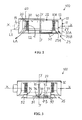
- FIG 2 is a vertical cross-sectional view of a first embodiment of the supply air terminal device shown in Figure 1 in a first operational mode.
- the supply air terminal device 100 comprises a cylindrical side wall 21 and a round cover plate 22, which closes the top end of the cylindrical side wall 21.
- a ring-shaped heat exchanger 30 is fitted, whose top end is supported against the cover plate's 22 lower surface.
- a ring-shaped mixing chamber 20 is formed in a space between the cylindrical side wall's 21 inner surface and the ring-shaped heat exchanger's 30 outer periphery a ring-shaped mixing chamber 20 is formed.
- the cylindrical side wall 21 forms the mixing chamber's 20 cylindrical outer side wall
- the heat exchanger's 30 outer periphery forms the mixing chamber's 20 cylindrical inner side wall
- the round cover plate 22 forms the mixing chamber's 20 ceiling.
- the cover plate's 22 lower surface, in the mixing chamber's 20 ceiling, at a distance from each other on the periphery of a circle M there are placed nozzles 60, through which a fresh airflow L1 is blown into the mixing chamber 20.
- the lower part of the supply air terminal device 100 is closed by a round bottom plate 50, which has a central section 51 provided with openings and a conical peripheral section 52.
- the central section 51 of bottom plate 50 is preferably formed by a removable aperture plate.
- the outer periphery of the bottom plate's 50 conical peripheral section 52 forms the inner periphery 25A of the ring-shaped output opening 25 in the lower part of mixing chamber 20.
- the lower part of the mixing chamber's 20 outer side wall 21 is formed with a conical shape, so that it forms the outer periphery 25B of the mixing chamber's 20 ring-shaped output opening 25.
- a cylindrical suction chamber 40 is formed in the space limited by the inner periphery of heat exchanger 30, the lower surface of cover plate 22 and the top surface of the bottom plate's 50 central section 51 provided with openings. In this first operational mode, the bottom plate 50 is in its top position.
- the supply air terminal device 100 also comprises a supply air chamber 10, in which there is a lower ring-shaped section 10A, which is formed outside the mixing chamber's 20 cylindrical outer side wall 21, and an upper compact cylindrical section 10B, which is formed above the cover plate 22.
- the supply air chamber 10 comprises a cylindrical outer side wall 11, which is located at a distance from the mixing chamber's 20 cylindrical outer side wall 21, and a round outer cover plate 12, which is located above cover plate 22, at a distance from this.
- the supply air chamber's 10 round outer cover plate 12 closes the top end of the supply air chamber's 10 cylindrical outer side wall 11. Between the supply air chamber's 10 round outer cover plate 12 and its lower round cover plate 22 a compact cylindrical space 10B is thus formed.
- the mixing chamber's 20 cylindrical outer side wall 21 forms the supply air chamber's 10 cylindrical inner side wall.
- the supply air chamber's 10 lower ring-shaped section 10A comprises a horizontal X-X supply air sleeve 15, from which the fresh airflow L1 is brought into the supply air chamber's 10 lower section 10A, from which it is guided upward into the upper compact section 10B of the supply air chamber 10 and from this forward through nozzles 60 and downward into the mixing chamber 20.
- the fresh airflow L1 will in the mixing chamber 20 form a vacuum, which will draw or induce a circulated airflow L2 from the air-conditioned room space into the suction chamber 40 and from this further on through the heat exchanger 30 into the mixing chamber 20, in which the fresh airflow L1 and the circulated airflow L2 form a combined airflow LA.
- the circulated airflow L2 can be cooled or heated in the heat exchanger 30.
- the combined airflow LA discharges from a ring-shaped conical output opening 25, which is located in the mixing chamber's 20 lower part, into the air-conditioned room space sideways and essentially in the direction of the room's ceiling surface.
- Figure 3 is a vertical cross-sectional view of a first embodiment of the supply air terminal device shown in Figure 1 in a second operating mode.
- the movable bottom plate 50 is here in its lower position, whereby the mixing chamber's 20 output opening 25 is largest.
- the supply air terminal device comprises a vertical Y-Y support shaft 71, whose top end is attached in a way allowing rotation to the lower surface of cover plate 22 and whose lower end comprises holes located in the transverse direction and at a distance from each other.
- a first bushing 73 which has a hole in the transverse direction, is fitted around the lower end of support shaft 71.
- a cotter pin 76 extends through the transverse hole of the first bushing 73 and one transverse hole of support shaft 71 forming a support point for the first bushing 73 in the support shaft 71.
- the inner end of a horizontal (X-X) support bar 72 is attached to the first bushing 73 and its outer end is attached to the bottom plate's 50 conical peripheral section 52.
- a second threaded bushing 75 is located in between the support bar's 72 inner end and outer end, which allows adjustment of the support bar's 72 length.
- the bottom plate 50 can be moved in the vertical direction Y-Y in the manner shown by arrow S by moving the first bushing 73 along the support shaft 71 and by locking it at the desired location with the cotter pin 76.
- a cylindrical third bushing 74 To the heat exchanger's 30 lower surface is attached a cylindrical third bushing 74, on whose outer surface the inner periphery of the bottom plate's 50 conical peripheral section 52 moves when the bottom plate 50 is lowered and raised in the vertical direction Y-Y.
- the mixing chamber's 20 output opening 25 is at its minimum, whereby a minimum airflow LA discharges from the output opening 25 out into the air-conditioned room space.
- the mixing chamber's 20 output opening 25 is at its maximum, whereby a maximum airflow LA discharges from output opening 25 and out into the air-conditioned room space.
- the bottom plate 50 can also be turned in the peripheral direction from the horizontal support bar 72, whereby the support shaft 71 will rotate at its point of attachment in the lower surface of cover plate 22.
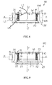
- FIG 4 is a vertical cross-sectional view of a second embodiment of the supply air terminal device in a first operating mode.
- This embodiment differs from the embodiment shown in Figure 2 in that the supply air chamber's 10 upper section 10B is ring-shaped.
- the supply air chamber's 10 upper section 10B is ring-shaped.
- This cylindrical inner side wall 41 of the supply air chamber's 10 upper section 10B forms the suction chamber's 40 upper outer side wall 41.
- the central part of outer cover 12 is provided with openings, whereby the circulated airflow L2 of the room space will travel through the outer cover's 12 openings into the suction chamber 40.
- the bottom plate 50 is here in its top position.
- Figure 5 is a vertical cross-sectional view of a second embodiment of the supply air terminal device shown in Figure 4 in a second operating mode.
- the bottom plate's 50 central part 51 and outer part 52 are here formed by one piece, which closes the suction chamber's 40 lower surface.
- the bottom plate 50 is similar to the bottom plate 50 shown in Figures 2 and 3 .
- a cylindrical bushing 74 is attached to the heat exchanger's 30 lower surface, and on its outer surface the inner surface of the bottom plate's 50 conical peripheral section 52 will move when the bottom plate 50 is lowered and raised in the vertical direction Y-Y.
- the S bottom plate 50 which can be moved in the vertical direction Y-Y is here in its lower position, whereby the mixing chamber's 20 output opening 25 is largest.
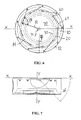
- FIG 6 is a vertical cross-sectional view of the first embodiment of the supply air terminal device shown in Figure 1 .
- the nozzles 60 are located at a distance from each other, preferably at equal distances, on the periphery of a circle M, in the ceiling of mixing chamber 20.
- the circle's M mid-point is located on the vertical central axis Y-Y of the supply air terminal device 100.
- the horizontal X-X component of the direction vector of the fresh airflow L1 discharging from each nozzle 60 forms an angle ⁇ with the radius R of said circle M.
- the angle ⁇ is preferably in a range of 45-135 degrees, most preferably 90 degrees.
- there are nine nozzles 60 but the number of nozzles 60 may of course vary.
- the supply air terminal device's diameter may vary in a range of 300-1200 mm.
- Figure 7 is a vertical cross-sectional view of a first embodiment of the supply air terminal device shown in Figure 1 .
- the direction vector of the fresh airflow L1 discharging from each nozzle 60 is also directed downward in relation to the horizontal direction X-X at an angle ⁇ , which is in a range of 15-75, preferably in a range of 30-60 degrees, most preferably 45 degrees, whereby a rotating airflow directed downward is formed in the mixing chamber 20.
- the nozzle arrangement shown in Figures 6 and 7 brings about in the mixing chamber 20 a rotating airflow directed downward, which discharges from the mixing chamber's 20 output opening 25 sideways in the direction of the ceiling as a rotating airflow.
- the rotating airflow improves the mixing together of the fresh airflow and the circulated airflow in the mixing chamber, whereby the difference between their temperatures will be quickly reduced.
- the rotating airflow discharging into the air-conditioned room space is mixed more quickly with the room air, and the velocity of the rotating airflow discharging into the room space will be reduced quickly. This improves the air distribution and the thermal conditions in the air-conditioned room space.
- the solution also improves the supply air terminal device's induction degree.
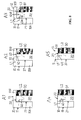
- Figure 8 shows cross-sectional views showing alternative embodiments of the supply air chamber and the nozzles.
- the cross-sections show one half of the supply air chamber 10, the mixing chamber 20 and the heat exchanger 30.
- the fresh airflow L1 is blown from the supply air chamber 10 through nozzles 60 into the mixing chamber 20.
- the circulated airflow L2 is conducted from the air-conditioned room space into the suction chamber located centrally in the supply air terminal device and then through the heat exchanger 30 into the mixing chamber 20.
- supply air chamber 10 corresponds with the embodiments shown in Figures 2-5 .
- a ring-shaped lower section 10A In the supply air chamber there is a ring-shaped lower section 10A and a compact or ring-shaped upper section 10B.
- a cylindrical outer wall 11 In the supply air chamber 10 there is a cylindrical outer wall 11, a cylindrical inner wall 21, a ceiling plate 22 and a roof plate 12.
- nozzles 60 are located in the mixing chamber's 20 outer wall, in embodiment A2, nozzles 60 are located in the mixing chamber's 20 ceiling plate.
- the first set of nozzles is formed by nozzles 60A, which are located in the mixing chamber's 20 outer wall 21, and a second set of nozzles is formed by nozzles 60B, which are located in the mixing chamber's 20 ceiling plate 22.
- a first set of nozzles 60A is located on the periphery of a first circle and a second set of nozzles 60A is located on the periphery of a second circle, whose radius is a bit shorter.
- the supply air chamber 10 is formed only by a supply air chamber, which surrounds the mixing chamber 20 and which thus corresponds with the lower supply air chamber 10A shown in the embodiments A1-A3.
- the top edge of the supply air chamber's 10 cylindrical outer side wall 11 extends to the level of the mixing chamber's 20 ceiling 22.
- the mixing chamber's 20 roof plate 22 thus forms the roof of supply air chamber 10 and of the entire supply air terminal device.
- Nozzles 60 are located in the mixing chamber's 20 outer side wall 21, which at the same time forms the supply air chamber's 10 inner side wall.
- the supply air chamber 10 is formed just by a supply air chamber above the mixing chamber 20, thus corresponding with the upper supply air chamber 10B shown in the embodiments A1-A3.
- the supply air chamber's 10 cylindrical outer side wall 11 joins the mixing chamber's 20 cylindrical outer side wall 21, whereby together they form the supply air terminal device's cylindrical outer wall.
- the mixing chamber's 20 ceiling plate 22 forms the supply air chamber's 10 bottom, and the supply air chamber's 10 roof plate 12 forms the supply air terminal device's roof.
- FIG. 9 shows cross-sections, which show alternative embodiments of the heat exchanger.
- the heat exchangers 30 are preferably finned tube heat exchangers.
- the heat exchanger 30 is formed by a loop having the shape of a circle.
- the liquid heat carrier flows from a first connection 31 into the heat exchanger 30 and from a second connection 32 from the heat exchanger 30.
- the heat exchanger 30 is formed by a spiral loop.
- the liquid heat carrier flows from a first connection 31 into the heat exchanger 30 and from a second connection 32 from the heat exchanger 30.
- the heat exchanger 30 is formed by two circular loops located one within the other.
- the liquid heat carrier flows from a first connection 31 into the heat exchanger 30 and from a second connection 32 from the heat exchanger 30.
- Figure 10 shows cross-sections, which show alternative embodiments of the bottom plate.
- the figures show a bottom plate 50, which thus comprises a central part 51, which may be solid or perforated, and a surrounding conical collar 52.
- the area shaded by oblique lines for its part shows the shape of the mixing chamber's 20 output opening 25.
- Embodiment C1 of Figure 10 shows a bottom plate 50, which is symmetrical in relation to the supply air terminal device's 100 vertical central axis Y-Y.
- the mixing chamber's 20 output opening 25 is here symmetrical in the whole peripheral area.
- Embodiment C2 of Figure 10 shows a bottom plate 50, which is eccentric in relation to the supply air terminal device's 100 vertical central axis Y-Y.
- the mixing chamber's 20 output opening 25 is formed with its left part larger at an approximate angle of 270 degrees and with its right part smaller at an approximate angle of 90 degrees.
- Embodiment C3 of Figure 10 shows an elliptical bottom plate 50.
- the mixing chamber's 20 output opening 25 corresponds in principle with the alternative shown in embodiment C2.
- Embodiment C4 of Figure 10 shows a strongly elliptical bottom plate 50.
- the mixing chamber's 20 output opening 25 is larger at the top and bottom at an approximate angle of 180 degrees and smaller on the left and on the right.
- the direction of eccentricity can be adjusted.
- the supply air chamber 10 is formed by a supply air chamber 10, which outside the outer periphery of the mixing chamber 20 comprises a compact or ring-shaped section 10A and above the mixing chamber 20 a ring-shaped section 10B, which join each other forming one compact supply air chamber 10.
- the supply air chamber 10 is formed by a ring-shaped supply air chamber 10 located outside the mixing chamber's 20 outer periphery.
- the supply air chamber 10 is formed only by a ring-shaped supply air chamber 10 located above the mixing chamber 20.
- the top section 10B of the supply air chamber 10 may thus be formed by one compact and open cylindrical space or by a ring-shaped chamber, whose cylindrical inner side wall at the same time forms the suction chamber's 40 outer wall.
- the supply air chamber 10 comprises only the section 10B above the mixing chamber 20, its cylindrical outer wall 11 joins the mixing chamber's 20 cylindrical outer wall 21.
- the cylindrical outer wall of section 10B above mixing chamber 20 joins the cylindrical outer wall 11 of section 10A below the mixing chamber 20.
- the supply air chamber's 10 outer wall 11 is cylindrical, but its cross-section may also be a square, a rectangle, a trapezium, or a polygon.
- the mixing chamber's 20 cover plate 22 must also be adapted to the shape of the supply chamber's 10 lower surface, in order to have a closed supply air chamber 10.
- the mixing chamber's 20 ceiling plate 22 hereby extends in a radial direction at least partly outside the mixing chamber's 20 outer side wall 21.
- the supply air sleeve 15 is in connection with the supply air chamber's 10 outer side wall 11. It can of course also be located in connection with the supply air chamber's 10 roof 12.
- the circulated air L2 enters the suction chamber 40 through the openings in the bottom plate's 50 central part 51, and in the embodiment shown in Figures 4-5 , the circulated air L2 enters the suction chamber 40 through the cover plate's 22 opening and through the outer cover plate's 12 perforation.
- the circulated air enters the suction chamber 40 from two directions, that is, both through the bottom plate's 50 and the cover plate's 22 opening and through the outer cover plate's 12 perforation.
- the cover plate 22 also forms the supply air terminal device's outer cover plate
- circulated air L2 is brought into the suction chamber 40 through the openings in the cover plate's 22 central part.
- the nozzles 60 may be located on the periphery of one or more circles.
- the embodiment A3 in Figure 8 has two nozzle sets 60A, 60B, which are located on the periphery of two circles whose radii are of different lengths. Both circles have there mid-point located on the supply air terminal device's vertical central axis Y-Y.
- the presentation in Figures 6 and 7 applies to the alignment of all nozzles 60A, 60B.
- the combined airflow is guided by the shape of the inner periphery 25A and outer periphery 25B of the ring-shaped output opening 25 in the lower part of mixing chamber 20 sideways into the air-conditioned room space.
- This is an advantageous solution, because the combined airflow will not hereby be guided directly at people in the air-conditioned room space causing a sense of draught.
- the inner periphery 25A and outer periphery 25B of the ring-shaped output opening 25 in the lower part of mixing chamber 20 may also be shaped in some other way, whereby the combined airflow can be directed, for example, directly downward, if need be.
Landscapes
- Engineering & Computer Science (AREA)
- Chemical & Material Sciences (AREA)
- Combustion & Propulsion (AREA)
- Mechanical Engineering (AREA)
- General Engineering & Computer Science (AREA)
- Duct Arrangements (AREA)
Abstract
Description
- The invention concerns a supply air terminal device in accordance with the preamble to claim 1.
- Supply air terminal devices or air-conditioning beams comprise a supply air chamber, a mixing chamber and a heat exchanger. The fresh airflow is brought from the supply air chamber into the mixing chamber, in which the fresh airflow is mixed with circulated air, whereupon the combined airflow is conducted into the room space. The circulated air is conducted into the mixing chamber through the heat exchanger, in which the circulated air can be heated or cooled. Using the same supply air terminal device it is possible in the summer time to attend to cooling of the room air and in the winter time to heating of the room air. In the summer time, the circulated air of the room is cooled, and in the winter time it is heated in the supply air terminal device's heat exchanger. The fresh airflow induces the circulated airflow to flow from the room through the heat exchanger and into the mixing chamber.
- The
DE 29822930 U1 utility model presents a round supply air terminal device. The embodiment shown inFigure 1 comprises a cylindrical outer side wall, whose top edge is closed with a first round cover plate. In the top part of the cylinder, at a distance from the first round cover plate there is a second round cover plate, whereby in the space between the first and the second round cover plate a cylindrical supply air chamber is formed. In the supply air chamber's cylindrical outer side wall a supply opening is formed for the fresh airflow. In the lower surface of the supply air chamber's bottom, that is, in the lower surface of the second round cover plate, a ring-shaped heat exchanger is attached, whereby in between the heat exchanger's outer periphery and the cylindrical outer side wall a ring-shaped mixing chamber is formed. In the mixing chamber's ceiling plate, that is, in the supply air chamber's bottom plate, nozzles are placed at equal intervals along a circle's periphery to lead the fresh airflow from the supply air chamber into the mixing chamber. To the heat exchanger's lower surface a first peripheral guiding part is attached to form the inner wall of the mixing chamber's ring-like output opening. To the lower edge of the cylindrical outer side wall again a second peripheral guiding part is attached to form the outer wall of the mixing chamber's peripheral output opening. In addition, to the inner wall of the output opening a round grating is attached, through which the air-conditioned room space's circulated air is led into a cylindrical suction chamber formed inside the ring-like heat exchanger. - In the solution presented in this
DE 29822930 U1 utility model, the fresh airflow is conducted from nozzles located in the mixing chamber's ceiling plate directly downward into the mixing chamber, wherein the fresh airflow is mixed with the circulated airflow forming a combined airflow. The circulated airflow is drawn from the air-conditioned room space through the round grating in the supply air terminal device's lower surface into the suction chamber and thence further through the heat exchanger and into the mixing chamber. The combined airflow is guided from a ring-like output opening in the mixing chamber's lower part sideways into the air-conditioned room space. The combined airflow travelling directly downward in the mixing chamber is discharged from the mixing chamber's output opening in a radial sideways direction into the air-conditioned room space. - The supply air terminal device according to the invention is characterized by the features presented in the characterizing part of
claim 1. - In the supply air terminal device according to the invention there is a ring-like mixing chamber and inside this a ring-like heat exchanger. In the ring-like mixing chamber there is a cylindrical outer wall and a ring-like inner wall, which is formed by the outer periphery of the ring-like heat exchanger. The fresh airflow is blown through nozzles into the mixing chamber. The circulated airflow is taken from the air-conditioned room into a suction chamber, which is limited by the ring-like heat exchanger's inner periphery and from which it travels through the heat exchanger into the mixing chamber. In the mixing chamber, the fresh airflow and the circulated airflow are mixed together forming a combined airflow. The nozzles are placed in the mixing chamber's upper part at a distance from each other on the periphery of at least one circle, and the centre of the at least one circle is located on the vertical central axis of the supply air terminal device.
- In the supply air terminal device according to the invention, the nozzles are placed on the periphery of said at least one circle in such a way that the horizontal component of the direction vector of the fresh airflow discharging from each nozzle forms an angle β, which is in a range of 45-135 degrees, preferably 90 degrees, with the radius of said circle, and the direction vector is directed downward, in relation to the horizontal plane at an angle α, which is in a range of 15-75 degrees, preferably 30-60 degrees, most preferably 45 degrees, whereby in the mixing chamber there is formed a rotating airflow directed downward.
- The rotating combined airflow formed in the mixing chamber and directed downward will discharge as a rotating airflow guided by the ring-like output opening of the mixing chamber sideways in the direction of the ceiling into the air-conditioned room space.
- The rotating airflow in the mixing chamber improves the mixture of fresh airflow and circulated air, whereby the difference in temperature between them will be reduced quickly. The rotating combined airflow discharging from the output opening of the mixing chamber into the air-conditioned room space is mixed in the same manner more quickly with the room air, whereby a quicker levelling out is achieved of the difference in temperature and velocity in the room space. The velocity of the rotating airflow discharged into the room space is also quickly reduced, whereby the sense of draught is avoided. The rotating airflow improves the distribution of air and the thermal conditions in the air-conditioned room space. The rotating airflow also improves the induction degree of the supply air terminal device.
- The invention will be described in the following by referring to some advantageous embodiments of the invention shown in the figures of the appended drawings, but there is no intention to restrict the invention to these alone.
-
-
Figure 1 is an axonometric view of a first embodiment of the supply air terminal device. -
Figure 2 is a vertical cross-sectional view of the first embodiment of the supply air terminal device shown inFigure 1 in a first operational mode. -
Figure 3 is a vertical cross-sectional view of the embodiment shown inFigure 2 in a second operational mode. -
Figure 4 is a vertical cross-sectional view of a second embodiment of the supply air terminal device in the first operational mode. -
Figure 5 is a vertical cross-sectional view of the embodiment shown inFigure 4 in the second operational mode. -
Figure 6 is a horizontal cross-sectional view of the first embodiment of the supply air terminal device shown inFigure 1 . -
Figure 7 is a vertical cross-sectional view of the first embodiment of the supply air terminal device shown inFigure 1 . -
Figure 8 shows cross-sectional views showing alternative embodiments of the supply air terminal device's supply air chamber and nozzles. -
Figure 9 shows cross-sectional views showing alternative embodiments of the supply air terminal device's heat exchanger. -
Figure 10 shows cross-sectional views showing alternative ways of embodying the supply air terminal device's bottom plate. -
Figure 1 is an axonometric view of a first embodiment of the supply air terminal device. A supplyair terminal device 100 having a round shape is installed inside a false ceiling K. A fresh airflow L1 is conducted from a freshair inlet sleeve 15 into a supply air chamber and from this further by way ofnozzles 60 into a ring-shaped mixing chamber 20. A circulated airflow L2 is conducted from a room space into acylindrical suction chamber 40, which is located inside a ring-shaped heat exchanger 30 and from which the circulated airflow L2 travels through theheat exchanger 30 into themixing chamber 20. The fresh airflow L1 and the circulated airflow L2 are combined in themixing chamber 20, whereupon the combined airflow LA is conducted from the mixing chamber's 20 output opening 25, which is located in the supply air terminal device's 100 lower surface, into the air-conditioned room space. The supplyair terminal device 100 has a vertical central axis Y-Y. -
Figure 2 is a vertical cross-sectional view of a first embodiment of the supply air terminal device shown inFigure 1 in a first operational mode. The supplyair terminal device 100 comprises acylindrical side wall 21 and around cover plate 22, which closes the top end of thecylindrical side wall 21. Inside thecylindrical side wall 21, at a distance from thecylindrical side wall 21, a ring-shaped heat exchanger 30 is fitted, whose top end is supported against the cover plate's 22 lower surface. In a space between the cylindrical side wall's 21 inner surface and the ring-shaped heat exchanger's 30 outer periphery a ring-shaped mixing chamber 20 is formed. Thecylindrical side wall 21 forms the mixing chamber's 20 cylindrical outer side wall, the heat exchanger's 30 outer periphery forms the mixing chamber's 20 cylindrical inner side wall, and theround cover plate 22 forms the mixing chamber's 20 ceiling. In the cover plate's 22 lower surface, in the mixing chamber's 20 ceiling, at a distance from each other on the periphery of a circle M there are placednozzles 60, through which a fresh airflow L1 is blown into themixing chamber 20. - The lower part of the supply
air terminal device 100 is closed by around bottom plate 50, which has acentral section 51 provided with openings and a conicalperipheral section 52. Thecentral section 51 ofbottom plate 50 is preferably formed by a removable aperture plate. The outer periphery of the bottom plate's 50 conicalperipheral section 52 forms theinner periphery 25A of the ring-shaped output opening 25 in the lower part ofmixing chamber 20. The lower part of the mixing chamber's 20outer side wall 21 is formed with a conical shape, so that it forms theouter periphery 25B of the mixing chamber's 20 ring-shaped output opening 25. Acylindrical suction chamber 40 is formed in the space limited by the inner periphery ofheat exchanger 30, the lower surface ofcover plate 22 and the top surface of the bottom plate's 50central section 51 provided with openings. In this first operational mode, thebottom plate 50 is in its top position. - The supply
air terminal device 100 also comprises asupply air chamber 10, in which there is a lower ring-shapedsection 10A, which is formed outside the mixing chamber's 20 cylindricalouter side wall 21, and an upper compactcylindrical section 10B, which is formed above thecover plate 22. Thesupply air chamber 10 comprises a cylindricalouter side wall 11, which is located at a distance from the mixing chamber's 20 cylindricalouter side wall 21, and a roundouter cover plate 12, which is located abovecover plate 22, at a distance from this. The supply air chamber's 10 roundouter cover plate 12 closes the top end of the supply air chamber's 10 cylindricalouter side wall 11. Between the supply air chamber's 10 roundouter cover plate 12 and its lower round cover plate 22 a compactcylindrical space 10B is thus formed. The mixing chamber's 20 cylindricalouter side wall 21 forms the supply air chamber's 10 cylindrical inner side wall. - The supply air chamber's 10 lower ring-shaped
section 10A comprises a horizontal X-Xsupply air sleeve 15, from which the fresh airflow L1 is brought into the supply air chamber's 10lower section 10A, from which it is guided upward into the uppercompact section 10B of thesupply air chamber 10 and from this forward throughnozzles 60 and downward into the mixingchamber 20. - The fresh airflow L1 will in the mixing
chamber 20 form a vacuum, which will draw or induce a circulated airflow L2 from the air-conditioned room space into thesuction chamber 40 and from this further on through theheat exchanger 30 into the mixingchamber 20, in which the fresh airflow L1 and the circulated airflow L2 form a combined airflow LA. The circulated airflow L2 can be cooled or heated in theheat exchanger 30. The combined airflow LA discharges from a ring-shapedconical output opening 25, which is located in the mixing chamber's 20 lower part, into the air-conditioned room space sideways and essentially in the direction of the room's ceiling surface. -
Figure 3 is a vertical cross-sectional view of a first embodiment of the supply air terminal device shown inFigure 1 in a second operating mode. In the vertical direction Y-Y themovable bottom plate 50 is here in its lower position, whereby the mixing chamber's 20output opening 25 is largest. In addition, the supply air terminal device comprises a verticalY-Y support shaft 71, whose top end is attached in a way allowing rotation to the lower surface ofcover plate 22 and whose lower end comprises holes located in the transverse direction and at a distance from each other. Afirst bushing 73, which has a hole in the transverse direction, is fitted around the lower end ofsupport shaft 71. Acotter pin 76 extends through the transverse hole of thefirst bushing 73 and one transverse hole ofsupport shaft 71 forming a support point for thefirst bushing 73 in thesupport shaft 71. The inner end of a horizontal (X-X)support bar 72 is attached to thefirst bushing 73 and its outer end is attached to the bottom plate's 50 conicalperipheral section 52. A second threadedbushing 75 is located in between the support bar's 72 inner end and outer end, which allows adjustment of the support bar's 72 length. - The
bottom plate 50 can be moved in the vertical direction Y-Y in the manner shown by arrow S by moving thefirst bushing 73 along thesupport shaft 71 and by locking it at the desired location with thecotter pin 76. To the heat exchanger's 30 lower surface is attached a cylindricalthird bushing 74, on whose outer surface the inner periphery of the bottom plate's 50 conicalperipheral section 52 moves when thebottom plate 50 is lowered and raised in the vertical direction Y-Y. When thebottom plate 50 is raised to the top position, the mixing chamber's 20output opening 25 is at its minimum, whereby a minimum airflow LA discharges from theoutput opening 25 out into the air-conditioned room space. When thebottom plate 50 is lowered to the lower position, the mixing chamber's 20output opening 25 is at its maximum, whereby a maximum airflow LA discharges fromoutput opening 25 and out into the air-conditioned room space. Thebottom plate 50 can also be turned in the peripheral direction from thehorizontal support bar 72, whereby thesupport shaft 71 will rotate at its point of attachment in the lower surface ofcover plate 22. -
Figure 4 is a vertical cross-sectional view of a second embodiment of the supply air terminal device in a first operating mode. This embodiment differs from the embodiment shown inFigure 2 in that the supply air chamber's 10upper section 10B is ring-shaped. In theupper section 10B ofsupply air chamber 10 there is a cylindricalinner side wall 41, which is located at the level of the heat exchanger's 30 inner periphery and which extends betweencover plate 22 and theouter cover plate 12. This cylindricalinner side wall 41 of the supply air chamber's 10upper section 10B forms the suction chamber's 40 upperouter side wall 41. There is an opening incover 22 in the area limited by the cylindrical suction chamber's 40upper side wall 41. The central part ofouter cover 12 is provided with openings, whereby the circulated airflow L2 of the room space will travel through the outer cover's 12 openings into thesuction chamber 40. Thebottom plate 50 is here in its top position. -
Figure 5 is a vertical cross-sectional view of a second embodiment of the supply air terminal device shown inFigure 4 in a second operating mode. The bottom plate's 50central part 51 andouter part 52 are here formed by one piece, which closes the suction chamber's 40 lower surface. In other respects, thebottom plate 50 is similar to thebottom plate 50 shown inFigures 2 and 3 . Here, too, acylindrical bushing 74 is attached to the heat exchanger's 30 lower surface, and on its outer surface the inner surface of the bottom plate's 50 conicalperipheral section 52 will move when thebottom plate 50 is lowered and raised in the vertical direction Y-Y. TheS bottom plate 50, which can be moved in the vertical direction Y-Y is here in its lower position, whereby the mixing chamber's 20output opening 25 is largest. -
Figure 6 is a vertical cross-sectional view of the first embodiment of the supply air terminal device shown inFigure 1 . As the figure shows, thenozzles 60 are located at a distance from each other, preferably at equal distances, on the periphery of a circle M, in the ceiling of mixingchamber 20. The circle's M mid-point is located on the vertical central axis Y-Y of the supplyair terminal device 100. The horizontal X-X component of the direction vector of the fresh airflow L1 discharging from eachnozzle 60 forms an angle β with the radius R of said circle M. The angle β is preferably in a range of 45-135 degrees, most preferably 90 degrees. In this embodiment there are ninenozzles 60, but the number ofnozzles 60 may of course vary. There is no upper limit for the number ofnozzles 60, but eightnozzles 60 may be regarded as a kind of lower limit, whereby there would be twonozzles 60 in each quadrant. An efficient turbulence is hereby achieved in the mixingchamber 20. The supply air terminal device's diameter may vary in a range of 300-1200 mm. -
Figure 7 is a vertical cross-sectional view of a first embodiment of the supply air terminal device shown inFigure 1 . As the figure shows, the direction vector of the fresh airflow L1 discharging from eachnozzle 60 is also directed downward in relation to the horizontal direction X-X at an angle α, which is in a range of 15-75, preferably in a range of 30-60 degrees, most preferably 45 degrees, whereby a rotating airflow directed downward is formed in the mixingchamber 20. - The nozzle arrangement shown in
Figures 6 and 7 brings about in the mixing chamber 20 a rotating airflow directed downward, which discharges from the mixing chamber's 20output opening 25 sideways in the direction of the ceiling as a rotating airflow. The rotating airflow improves the mixing together of the fresh airflow and the circulated airflow in the mixing chamber, whereby the difference between their temperatures will be quickly reduced. The rotating airflow discharging into the air-conditioned room space is mixed more quickly with the room air, and the velocity of the rotating airflow discharging into the room space will be reduced quickly. This improves the air distribution and the thermal conditions in the air-conditioned room space. The solution also improves the supply air terminal device's induction degree. -
Figure 8 shows cross-sectional views showing alternative embodiments of the supply air chamber and the nozzles. The cross-sections show one half of thesupply air chamber 10, the mixingchamber 20 and theheat exchanger 30. The fresh airflow L1 is blown from thesupply air chamber 10 throughnozzles 60 into the mixingchamber 20. The circulated airflow L2 is conducted from the air-conditioned room space into the suction chamber located centrally in the supply air terminal device and then through theheat exchanger 30 into the mixingchamber 20. - In the embodiments A1-A3 of
Figure 8 ,supply air chamber 10 corresponds with the embodiments shown inFigures 2-5 . In the supply air chamber there is a ring-shapedlower section 10A and a compact or ring-shapedupper section 10B. In thesupply air chamber 10 there is a cylindricalouter wall 11, a cylindricalinner wall 21, aceiling plate 22 and aroof plate 12. In embodiment A1,nozzles 60 are located in the mixing chamber's 20 outer wall, in embodiment A2,nozzles 60 are located in the mixing chamber's 20 ceiling plate. In embodiment A3, the first set of nozzles is formed bynozzles 60A, which are located in the mixing chamber's 20outer wall 21, and a second set of nozzles is formed by nozzles 60B, which are located in the mixing chamber's 20ceiling plate 22. In embodiment A3, a first set ofnozzles 60A is located on the periphery of a first circle and a second set ofnozzles 60A is located on the periphery of a second circle, whose radius is a bit shorter. - In embodiment A4 of
Figure 8 , thesupply air chamber 10 is formed only by a supply air chamber, which surrounds the mixingchamber 20 and which thus corresponds with the lowersupply air chamber 10A shown in the embodiments A1-A3. The top edge of the supply air chamber's 10 cylindricalouter side wall 11 extends to the level of the mixing chamber's 20ceiling 22. The mixing chamber's 20roof plate 22 thus forms the roof ofsupply air chamber 10 and of the entire supply air terminal device.Nozzles 60 are located in the mixing chamber's 20outer side wall 21, which at the same time forms the supply air chamber's 10 inner side wall. - In embodiment A5 of
Figure 8 , thesupply air chamber 10 is formed just by a supply air chamber above the mixingchamber 20, thus corresponding with the uppersupply air chamber 10B shown in the embodiments A1-A3. The supply air chamber's 10 cylindricalouter side wall 11 joins the mixing chamber's 20 cylindricalouter side wall 21, whereby together they form the supply air terminal device's cylindrical outer wall. The mixing chamber's 20ceiling plate 22 forms the supply air chamber's 10 bottom, and the supply air chamber's 10roof plate 12 forms the supply air terminal device's roof. -
Figure 9 shows cross-sections, which show alternative embodiments of the heat exchanger. Theheat exchangers 30 are preferably finned tube heat exchangers. - In embodiment B1 of
Figure 9 , theheat exchanger 30 is formed by a loop having the shape of a circle. The liquid heat carrier flows from afirst connection 31 into theheat exchanger 30 and from asecond connection 32 from theheat exchanger 30. - In embodiment B2 of
Figure 9 , theheat exchanger 30 is formed by a spiral loop. The liquid heat carrier flows from afirst connection 31 into theheat exchanger 30 and from asecond connection 32 from theheat exchanger 30. - In embodiment B3 of
Figure 9 , theheat exchanger 30 is formed by two circular loops located one within the other. The liquid heat carrier flows from afirst connection 31 into theheat exchanger 30 and from asecond connection 32 from theheat exchanger 30. - With two circles or with a spiral heat exchanger a great difference in temperature is achieved between the liquid heat carrier circulating in the
heat exchanger 30 and the air, and thus a high heat-transfer coefficient is achieved. -
Figure 10 shows cross-sections, which show alternative embodiments of the bottom plate. The figures show abottom plate 50, which thus comprises acentral part 51, which may be solid or perforated, and a surroundingconical collar 52. The area shaded by oblique lines for its part shows the shape of the mixing chamber's 20output opening 25. - Embodiment C1 of
Figure 10 shows abottom plate 50, which is symmetrical in relation to the supply air terminal device's 100 vertical central axis Y-Y. The mixing chamber's 20output opening 25 is here symmetrical in the whole peripheral area. - Embodiment C2 of
Figure 10 shows abottom plate 50, which is eccentric in relation to the supply air terminal device's 100 vertical central axis Y-Y. The mixing chamber's 20output opening 25 is formed with its left part larger at an approximate angle of 270 degrees and with its right part smaller at an approximate angle of 90 degrees. By moving the eccentricity of theX1 bottom plate 50 it is possible to adjust the eccentricity's strength. By turning theR1 bottom plate 50 it is possible to adjust the direction of the eccentricity. - Embodiment C3 of
Figure 10 shows anelliptical bottom plate 50. Here the mixing chamber's 20output opening 25 corresponds in principle with the alternative shown in embodiment C2. By turning theR1 bottom plate 50 it is possible to adjust the direction of the eccentricity. - Embodiment C4 of
Figure 10 shows a stronglyelliptical bottom plate 50. The mixing chamber's 20output opening 25 is larger at the top and bottom at an approximate angle of 180 degrees and smaller on the left and on the right. By turning theR1 bottom plate 50 the direction of eccentricity can be adjusted. - In the embodiments A1-A3 of
Figure 8 , thesupply air chamber 10 is formed by asupply air chamber 10, which outside the outer periphery of the mixingchamber 20 comprises a compact or ring-shapedsection 10A and above the mixing chamber 20 a ring-shapedsection 10B, which join each other forming one compactsupply air chamber 10. In embodiment A4 ofFigure 8 , thesupply air chamber 10 is formed by a ring-shapedsupply air chamber 10 located outside the mixing chamber's 20 outer periphery. In embodiment A5 ofFigure 8 , thesupply air chamber 10 is formed only by a ring-shapedsupply air chamber 10 located above the mixingchamber 20. - The
top section 10B of thesupply air chamber 10 may thus be formed by one compact and open cylindrical space or by a ring-shaped chamber, whose cylindrical inner side wall at the same time forms the suction chamber's 40 outer wall. In a situation where thesupply air chamber 10 comprises only thesection 10B above the mixingchamber 20, its cylindricalouter wall 11 joins the mixing chamber's 20 cylindricalouter wall 21. In a situation where thesupply air chamber 10 comprises bothsection 10B above mixingchamber 20 andsection 10A outside mixingchamber 20, the cylindrical outer wall ofsection 10B above mixingchamber 20 joins the cylindricalouter wall 11 ofsection 10A below the mixingchamber 20. - In the embodiments shown in the figures, the supply air chamber's 10
outer wall 11 is cylindrical, but its cross-section may also be a square, a rectangle, a trapezium, or a polygon. In a situation where thesupply air chamber 10 is only located above the mixingchamber 20 and its outer wall is of a shape other than cylindrical, the mixing chamber's 20cover plate 22 must also be adapted to the shape of the supply chamber's 10 lower surface, in order to have a closedsupply air chamber 10. The mixing chamber's 20ceiling plate 22 hereby extends in a radial direction at least partly outside the mixing chamber's 20outer side wall 21. - In the embodiments shown in the figures, the
supply air sleeve 15 is in connection with the supply air chamber's 10outer side wall 11. It can of course also be located in connection with the supply air chamber's 10roof 12. - In the embodiment shown in
Figures 2-3 , the circulated air L2 enters thesuction chamber 40 through the openings in the bottom plate's 50central part 51, and in the embodiment shown inFigures 4-5 , the circulated air L2 enters thesuction chamber 40 through the cover plate's 22 opening and through the outer cover plate's 12 perforation. Such an embodiment is also possible, where the circulated air enters thesuction chamber 40 from two directions, that is, both through the bottom plate's 50 and the cover plate's 22 opening and through the outer cover plate's 12 perforation. In a situation where thecover plate 22 also forms the supply air terminal device's outer cover plate, circulated air L2 is brought into thesuction chamber 40 through the openings in the cover plate's 22 central part. - The
nozzles 60 may be located on the periphery of one or more circles. The embodiment A3 inFigure 8 has two nozzle sets 60A, 60B, which are located on the periphery of two circles whose radii are of different lengths. Both circles have there mid-point located on the supply air terminal device's vertical central axis Y-Y. The presentation inFigures 6 and 7 applies to the alignment of allnozzles 60A, 60B. - In the embodiments shown in the figures, the combined airflow is guided by the shape of the
inner periphery 25A andouter periphery 25B of the ring-shapedoutput opening 25 in the lower part of mixingchamber 20 sideways into the air-conditioned room space. This is an advantageous solution, because the combined airflow will not hereby be guided directly at people in the air-conditioned room space causing a sense of draught. However, theinner periphery 25A andouter periphery 25B of the ring-shapedoutput opening 25 in the lower part of mixingchamber 20 may also be shaped in some other way, whereby the combined airflow can be directed, for example, directly downward, if need be. - Only some advantageous embodiments of the invention were presented above, and it is obvious to an expert in the art that numerous modifications can be made to them within the scope of the appended claims.
Claims (9)
- Supply air terminal device (100), which comprises:- a cylindrical side wall (21),- a ring-shaped heat exchanger (30), which is located inside the cylindrical side wall (21), at a distance from the cylindrical side wall (21),- a cover plate (22), against which the top ends of the cylindrical side wall (21) and of the ring-shaped heat exchanger (30) are supported,- a ring-shaped mixing chamber (20), which is formed in between a space between the cylindrical side wall (21) and the ring-shaped heat exchanger (30), whereby the cylindrical side wall (21) forms the mixing chamber's (20) cylindrical outer side wall, the heat exchanger's (30) outer periphery forms the mixing chamber's (20) cylindrical inner side wall, and the cover plate (22) forms the mixing chamber's (20) roof plate,- a vertical central axis (Y-Y),- nozzles (60), which are placed in the upper part of the mixing chamber (20) at a distance from each other on the periphery of at least one circle (M), whereby the mid-point of the at least one circle (M) is located on the vertical central axis (Y-Y) of the supply air terminal device (100),- a supply air chamber (10), from which a fresh airflow (L1) is conducted to the nozzles (60),- a bottom plate (50), which comprises at least a section of a periphery (52), in which there are an inner periphery and an outer periphery,- a ring-shaped output opening (25), which is located in the lower part of the mixing chamber (20) and which comprises an inner periphery (25A) and an outer periphery (25B),- a cylindrical suction chamber (40), which is formed in a space limited by the inner periphery of the heat exchanger (30) and into which circulated air (L2) is drawn from the air-conditioned room space,characterized in that:- the nozzles (60) are placed on the periphery of said at least one circle (M) in such a way that the horizontal (X-X) component of the direction vector of the fresh airflow (L1) discharging from each nozzle (60) forms an angle (β), which is in a range of 45-135 degrees, with the radius (R) of said circle (M), and the direction vector is directed downward in relation to the horizontal plane at an angle α, which is in a range of 15-75 degrees,- whereby a rotating airflow directed downward is formed in the mixing chamber (20).
- Supply air terminal device (100) according to claim 1, characterized in that the supply air chamber (10) is formed:- by a lower section (10A), which is formed around the cylindrical outer side wall (21) of the mixing chamber (20), so that the supply air chamber's (10) outer side wall (11) is formed by a cylindrical outer side wall (11), which is located outside the mixing chamber's (20) cylindrical outer side wall (21), at a distance from this, and- by an upper section (10B), which is formed above the cover plate (22), so that the supply air chamber's (10) outer cover plate (12) is formed by a round outer cover plate (12), which is located above the cover plate (22), at a distance from this and which closes the top end of the supply air chamber's (10) cylindrical outer side wall (11).
- Supply air terminal device (100) according to claim 1 or 2, characterized in that:- the bottom plate's (50) peripheral section (52) comprises a conical outer periphery, which forms the ring-shaped output opening's (25) inner periphery (25A),- the mixing chamber's (20) cylindrical outer side wall (21) comprises a conical lower part, which forms the ring-shaped output opening's (25) outer periphery (25B),- whereby the ring-shaped output opening (25) guides the combined airflow (LA) discharging from the mixing chamber (20) sideways in the direction of the ceiling into the air-conditioned room space.
- Supply air terminal device (100) according to any of claims 1-3, characterized in that the supply air terminal device (100) also comprises:- a vertical (Y-Y) support shaft (71), whose top end is attached in a way allowing rotation to the lower surface of cover plate (22) and whose lower end comprises holes in a transverse direction and located at a distance from each other,- a first bushing (73), in which there is a transverse hole and which is fitted around the support shaft (71),- a cotter pin (76), which extends through the transverse hole of the first bushing (73) and one transverse hole of the support shaft (71) forming a point of attachment for the first bushing (73) in the support shaft (71),- a horizontal (X-X) support bar (72), whereby the inner end of the support bar (72) is attached to the first bushing (73) and the outer end of the support bar (72) is attached to the bottom plate's (50) conical peripheral section (52),- a second threaded bushing (75) in between the support bar's (72) inner end and outer end, for adjusting the length of the support bar (72),- whereby the bottom plate (50) can be moved vertically (Y-Y) by moving the point of attachment of the first bushing (73) on the support shaft (71) and in the horizontal direction (X-X) by turning the second threaded bushing (75).
- Supply air terminal device (10) according to claim 4, characterized in that to the heat exchanger's (30) lower surface is attached a third cylindrical bushing (74), on whose outer surface the inner periphery of the bottom plate's (50) peripheral section (52) will move when the bottom plate (50) is lowered and raised in the vertical direction (Y-Y) by moving the point of attachment of the first bushing (73) on the support shaft (71).
- Supply air terminal device (10) according to any of claims 1-5, characterized in that the bottom plate (50) comprises the peripheral section's (52) inner central section (51), in which there are openings, through which circulated air (L2) may travel from the air-conditioned room space into the suction chamber (40).
- Supply air terminal device (10) according to any of claims 1-6, characterized in that the bottom plate's (50) central section (51) is formed by a round perforated plate (51), which is removable.
- Supply air terminal device (10) according to any of claims 1-7, characterized in that in the central part of the supply air terminal device's (10) cover plate (21) and/or outer cover plate (12) there is a section, which is provided with at least one opening and through which circulated air (L2) travels from the air-conditioned room space into the suction chamber (40).
- Supply air terminal device (10) according to any of claims 1-8, characterized in that the outer periphery of the bottom plate's (50) peripheral section (52) has an elliptical shape, whereby the mixing chamber's (20) output opening (25) is also formed with an elliptical shape.
Priority Applications (1)
| Application Number | Priority Date | Filing Date | Title |
|---|---|---|---|
| PL10165514T PL2282134T3 (en) | 2009-07-03 | 2010-06-10 | Supply air terminal device for ceiling installation with inclined nozzles for swirl generation |
Applications Claiming Priority (1)
| Application Number | Priority Date | Filing Date | Title |
|---|---|---|---|
| FI20095754A FI122961B (en) | 2009-07-03 | 2009-07-03 | Tilluftanordning |
Publications (2)
| Publication Number | Publication Date |
|---|---|
| EP2282134A1 true EP2282134A1 (en) | 2011-02-09 |
| EP2282134B1 EP2282134B1 (en) | 2018-08-01 |
Family
ID=40935834
Family Applications (1)
| Application Number | Title | Priority Date | Filing Date |
|---|---|---|---|
| EP10165514.0A Not-in-force EP2282134B1 (en) | 2009-07-03 | 2010-06-10 | Supply air terminal device for ceiling installation with inclined nozzles for swirl generation |
Country Status (5)
| Country | Link |
|---|---|
| US (1) | US9222683B2 (en) |
| EP (1) | EP2282134B1 (en) |
| FI (1) | FI122961B (en) |
| PL (1) | PL2282134T3 (en) |
| RU (1) | RU2535270C2 (en) |
Cited By (5)
| Publication number | Priority date | Publication date | Assignee | Title |
|---|---|---|---|---|
| CN103256658A (en) * | 2013-03-01 | 2013-08-21 | 广东美的制冷设备有限公司 | Floor type air conditioner indoor unit |
| CN104833019A (en) * | 2015-04-14 | 2015-08-12 | 徐州天一红点车用空调有限公司 | Lantern type air-conditioner indoor unit |
| CN106979554A (en) * | 2016-01-15 | 2017-07-25 | 三星电子株式会社 | Air-conditioning |
| RU2684679C1 (en) * | 2017-11-14 | 2019-04-11 | Федеральное государственное образовательное учреждение высшего образования "Юго-Западный государственный университет" (ЮЗГУ) | Mobile device for removing contaminated outdoor air |
| CN112432349A (en) * | 2020-11-13 | 2021-03-02 | 广东美的白色家电技术创新中心有限公司 | Air supply mechanism and air conditioner |
Families Citing this family (6)
| Publication number | Priority date | Publication date | Assignee | Title |
|---|---|---|---|---|
| CN104390267B (en) * | 2014-10-31 | 2017-05-24 | 广东美的制冷设备有限公司 | Air conditioner and air supplying method of air conditioner |
| US9557070B2 (en) * | 2015-05-07 | 2017-01-31 | Samsung Electronics Co., Ltd. | Air conditioner and method for controlling the same |
| KR101881907B1 (en) | 2015-10-23 | 2018-07-27 | 삼성전자주식회사 | Air conditioner and cotrolling method thereof |
| US11460200B2 (en) * | 2018-08-21 | 2022-10-04 | Kenneth Horvath | Method and apparatus for air circulation and purification |
| US11561017B2 (en) * | 2019-12-09 | 2023-01-24 | Air Distribution Technologies Ip, Llc | Exhaust fan unit of a heating, ventilation, and/or air conditioning (HVAC) system |
| IT202000018085A1 (en) * | 2020-07-27 | 2022-01-27 | Andrea Cagni | DOUBLE EMISSION CLEAN AIR DIFFUSER AND CORRESPONDING AIR EXCHANGE SYSTEM |
Citations (2)
| Publication number | Priority date | Publication date | Assignee | Title |
|---|---|---|---|---|
| DE1778188A1 (en) * | 1968-04-04 | 1971-11-04 | Gerhard Scott | Air conditioning unit that can be installed in the ceilings of rooms |
| DE29822930U1 (en) * | 1998-12-23 | 1999-02-25 | Gebrüder Trox, GmbH, 47506 Neukirchen-Vluyn | Ceiling air outlet for air conditioning systems |
Family Cites Families (13)
| Publication number | Priority date | Publication date | Assignee | Title |
|---|---|---|---|---|
| SU502181A2 (en) * | 1973-08-07 | 1976-02-05 | Всесоюзный Научно-Исследовательский И Проектно-Конструкторский Институт По Оборудованию Для Кондиционирования Воздуха И Вентиляции "Вниикондбентмаш" | Mixing camera |
| DE3229212A1 (en) * | 1982-08-05 | 1984-02-09 | Erwin Müller GmbH & Co, 4450 Lingen | Air outlet device for ventilating and air-conditioning plants |
| DE4405738C1 (en) | 1994-02-23 | 1995-06-08 | Schako Metallwarenfabrik | Swirl inducing outlet |
| US6203421B1 (en) * | 2000-01-29 | 2001-03-20 | Ervin H. Black | Safety ceiling vent |
| DE20102737U1 (en) * | 2001-02-16 | 2001-07-19 | Rud. Otto Meyer GmbH & Co. KG, 22047 Hamburg | Air outlet device and associated air conditioning device |
| KR101160401B1 (en) * | 2007-10-25 | 2012-06-26 | 도시바 캐리어 가부시키가이샤 | Ceiling-embedded air conditioner |
| EP2246637B1 (en) * | 2008-01-25 | 2017-06-07 | Daikin Industries, Ltd. | Indoor unit of air conditioning apparatus |
| US20090264062A1 (en) * | 2008-04-16 | 2009-10-22 | Nuclimate Air Quality Systems, Inc. | Ventilation system |
| KR101558576B1 (en) * | 2009-01-09 | 2015-10-19 | 엘지전자 주식회사 | The indoor unit of the air conditioner |
| KR101624743B1 (en) * | 2009-01-09 | 2016-05-26 | 엘지전자 주식회사 | Indoor unit of air conditioner |
| KR101558575B1 (en) * | 2009-01-09 | 2015-10-07 | 엘지전자 주식회사 | Air conditioner indoor unit |
| JP5359458B2 (en) * | 2009-03-27 | 2013-12-04 | ダイキン工業株式会社 | Air conditioner, casing, and decorative panel |
| AU2010201383B9 (en) * | 2009-04-13 | 2011-06-02 | Kimura Kohki Co., Ltd. | Heating and cooling unit, and heating and cooling apparatus |
-
2009
- 2009-07-03 FI FI20095754A patent/FI122961B/en active IP Right Grant
-
2010
- 2010-06-10 EP EP10165514.0A patent/EP2282134B1/en not_active Not-in-force
- 2010-06-10 PL PL10165514T patent/PL2282134T3/en unknown
- 2010-06-23 US US12/821,572 patent/US9222683B2/en not_active Expired - Fee Related
- 2010-07-02 RU RU2010127263/12A patent/RU2535270C2/en active
Patent Citations (2)
| Publication number | Priority date | Publication date | Assignee | Title |
|---|---|---|---|---|
| DE1778188A1 (en) * | 1968-04-04 | 1971-11-04 | Gerhard Scott | Air conditioning unit that can be installed in the ceilings of rooms |
| DE29822930U1 (en) * | 1998-12-23 | 1999-02-25 | Gebrüder Trox, GmbH, 47506 Neukirchen-Vluyn | Ceiling air outlet for air conditioning systems |
Cited By (6)
| Publication number | Priority date | Publication date | Assignee | Title |
|---|---|---|---|---|
| CN103256658A (en) * | 2013-03-01 | 2013-08-21 | 广东美的制冷设备有限公司 | Floor type air conditioner indoor unit |
| CN103256658B (en) * | 2013-03-01 | 2015-08-19 | 广东美的制冷设备有限公司 | Floor air conditioner indoor machine |
| CN104833019A (en) * | 2015-04-14 | 2015-08-12 | 徐州天一红点车用空调有限公司 | Lantern type air-conditioner indoor unit |
| CN106979554A (en) * | 2016-01-15 | 2017-07-25 | 三星电子株式会社 | Air-conditioning |
| RU2684679C1 (en) * | 2017-11-14 | 2019-04-11 | Федеральное государственное образовательное учреждение высшего образования "Юго-Западный государственный университет" (ЮЗГУ) | Mobile device for removing contaminated outdoor air |
| CN112432349A (en) * | 2020-11-13 | 2021-03-02 | 广东美的白色家电技术创新中心有限公司 | Air supply mechanism and air conditioner |
Also Published As
| Publication number | Publication date |
|---|---|
| FI20095754A0 (en) | 2009-07-03 |
| US20110000566A1 (en) | 2011-01-06 |
| RU2010127263A (en) | 2012-01-10 |
| US9222683B2 (en) | 2015-12-29 |
| RU2535270C2 (en) | 2014-12-10 |
| FI122961B (en) | 2012-09-14 |
| EP2282134B1 (en) | 2018-08-01 |
| PL2282134T3 (en) | 2018-12-31 |
| FI20095754A7 (en) | 2011-01-04 |
Similar Documents
| Publication | Publication Date | Title |
|---|---|---|
| EP2282134B1 (en) | Supply air terminal device for ceiling installation with inclined nozzles for swirl generation | |
| US6050892A (en) | Adjustable floor-mounted air outlet vent | |
| JP2012042085A (en) | Induction blow port | |
| KR102610037B1 (en) | Ceiling type air conditioner | |
| CN110056951B (en) | An air outlet device, an air conditioner indoor unit and an air conditioner | |
| CN106482193A (en) | A kind of have air-conditioned range hood | |
| JP5198620B2 (en) | One span air conditioning system | |
| CN112178764A (en) | Air conditioner | |
| KR102313903B1 (en) | ceiling type air conditioner | |
| CN111853939A (en) | Air conditioner and air outlet control method thereof | |
| CN113639316B (en) | Air conditioner and induced air outlet device for air conditioner | |
| CN212179040U (en) | Ceiling machine | |
| KR102285819B1 (en) | Ceiling type air conditioner | |
| CN209165719U (en) | A kind of wall rotation visualization wind outlet unit | |
| CN113639315B (en) | Air conditioner and induced air outlet device for air conditioner | |
| CN215929826U (en) | Air conditioner | |
| CN207501261U (en) | Air conditioner indoor unit and air conditioner | |
| KR100227603B1 (en) | Air supply system of floor ejecting air conditioning system | |
| CN107143925A (en) | Raise type air conditioner | |
| JP2001050577A (en) | Air supply unit for air conditioning | |
| CN113357808A (en) | Air deflector and embedded air conditioner | |
| KR100202280B1 (en) | Air supply system of floor ejecting air conditioning system | |
| CN112432241B (en) | Reversible air supply air conditioner | |
| CN210886705U (en) | Air outlet structure of garment steamer | |
| EP2775223B1 (en) | Air supply nozzle |
Legal Events
| Date | Code | Title | Description |
|---|---|---|---|
| PUAI | Public reference made under article 153(3) epc to a published international application that has entered the european phase |
Free format text: ORIGINAL CODE: 0009012 |
|
| 17P | Request for examination filed |
Effective date: 20100610 |
|
| AK | Designated contracting states |
Kind code of ref document: A1 Designated state(s): AL AT BE BG CH CY CZ DE DK EE ES FI FR GB GR HR HU IE IS IT LI LT LU LV MC MK MT NL NO PL PT RO SE SI SK SM TR |
|
| AX | Request for extension of the european patent |
Extension state: BA ME RS |
|
| STAA | Information on the status of an ep patent application or granted ep patent |
Free format text: STATUS: EXAMINATION IS IN PROGRESS |
|
| 17Q | First examination report despatched |
Effective date: 20170808 |
|
| GRAP | Despatch of communication of intention to grant a patent |
Free format text: ORIGINAL CODE: EPIDOSNIGR1 |
|
| STAA | Information on the status of an ep patent application or granted ep patent |
Free format text: STATUS: GRANT OF PATENT IS INTENDED |
|
| INTG | Intention to grant announced |
Effective date: 20180119 |
|
| GRAS | Grant fee paid |
Free format text: ORIGINAL CODE: EPIDOSNIGR3 |
|
| GRAA | (expected) grant |
Free format text: ORIGINAL CODE: 0009210 |
|
| STAA | Information on the status of an ep patent application or granted ep patent |
Free format text: STATUS: THE PATENT HAS BEEN GRANTED |
|
| AK | Designated contracting states |
Kind code of ref document: B1 Designated state(s): AL AT BE BG CH CY CZ DE DK EE ES FI FR GB GR HR HU IE IS IT LI LT LU LV MC MK MT NL NO PL PT RO SE SI SK SM TR |
|
| REG | Reference to a national code |
Ref country code: GB Ref legal event code: FG4D |
|
| REG | Reference to a national code |
Ref country code: CH Ref legal event code: EP Ref country code: AT Ref legal event code: REF Ref document number: 1024753 Country of ref document: AT Kind code of ref document: T Effective date: 20180815 |
|
| REG | Reference to a national code |
Ref country code: IE Ref legal event code: FG4D |
|
| REG | Reference to a national code |
Ref country code: DE Ref legal event code: R096 Ref document number: 602010052296 Country of ref document: DE |
|
| REG | Reference to a national code |
Ref country code: NL Ref legal event code: FP |
|
| REG | Reference to a national code |
Ref country code: SE Ref legal event code: TRGR |
|
| REG | Reference to a national code |
Ref country code: LT Ref legal event code: MG4D |
|
| REG | Reference to a national code |
Ref country code: AT Ref legal event code: MK05 Ref document number: 1024753 Country of ref document: AT Kind code of ref document: T Effective date: 20180801 |
|
| PG25 | Lapsed in a contracting state [announced via postgrant information from national office to epo] |
Ref country code: LT Free format text: LAPSE BECAUSE OF FAILURE TO SUBMIT A TRANSLATION OF THE DESCRIPTION OR TO PAY THE FEE WITHIN THE PRESCRIBED TIME-LIMIT Effective date: 20180801 Ref country code: AT Free format text: LAPSE BECAUSE OF FAILURE TO SUBMIT A TRANSLATION OF THE DESCRIPTION OR TO PAY THE FEE WITHIN THE PRESCRIBED TIME-LIMIT Effective date: 20180801 Ref country code: BG Free format text: LAPSE BECAUSE OF FAILURE TO SUBMIT A TRANSLATION OF THE DESCRIPTION OR TO PAY THE FEE WITHIN THE PRESCRIBED TIME-LIMIT Effective date: 20181101 Ref country code: IS Free format text: LAPSE BECAUSE OF FAILURE TO SUBMIT A TRANSLATION OF THE DESCRIPTION OR TO PAY THE FEE WITHIN THE PRESCRIBED TIME-LIMIT Effective date: 20181201 Ref country code: NO Free format text: LAPSE BECAUSE OF FAILURE TO SUBMIT A TRANSLATION OF THE DESCRIPTION OR TO PAY THE FEE WITHIN THE PRESCRIBED TIME-LIMIT Effective date: 20181101 Ref country code: GR Free format text: LAPSE BECAUSE OF FAILURE TO SUBMIT A TRANSLATION OF THE DESCRIPTION OR TO PAY THE FEE WITHIN THE PRESCRIBED TIME-LIMIT Effective date: 20181102 |
|
| PG25 | Lapsed in a contracting state [announced via postgrant information from national office to epo] |
Ref country code: ES Free format text: LAPSE BECAUSE OF FAILURE TO SUBMIT A TRANSLATION OF THE DESCRIPTION OR TO PAY THE FEE WITHIN THE PRESCRIBED TIME-LIMIT Effective date: 20180801 Ref country code: LV Free format text: LAPSE BECAUSE OF FAILURE TO SUBMIT A TRANSLATION OF THE DESCRIPTION OR TO PAY THE FEE WITHIN THE PRESCRIBED TIME-LIMIT Effective date: 20180801 Ref country code: HR Free format text: LAPSE BECAUSE OF FAILURE TO SUBMIT A TRANSLATION OF THE DESCRIPTION OR TO PAY THE FEE WITHIN THE PRESCRIBED TIME-LIMIT Effective date: 20180801 Ref country code: AL Free format text: LAPSE BECAUSE OF FAILURE TO SUBMIT A TRANSLATION OF THE DESCRIPTION OR TO PAY THE FEE WITHIN THE PRESCRIBED TIME-LIMIT Effective date: 20180801 |
|
| PG25 | Lapsed in a contracting state [announced via postgrant information from national office to epo] |
Ref country code: EE Free format text: LAPSE BECAUSE OF FAILURE TO SUBMIT A TRANSLATION OF THE DESCRIPTION OR TO PAY THE FEE WITHIN THE PRESCRIBED TIME-LIMIT Effective date: 20180801 Ref country code: IT Free format text: LAPSE BECAUSE OF FAILURE TO SUBMIT A TRANSLATION OF THE DESCRIPTION OR TO PAY THE FEE WITHIN THE PRESCRIBED TIME-LIMIT Effective date: 20180801 Ref country code: CZ Free format text: LAPSE BECAUSE OF FAILURE TO SUBMIT A TRANSLATION OF THE DESCRIPTION OR TO PAY THE FEE WITHIN THE PRESCRIBED TIME-LIMIT Effective date: 20180801 Ref country code: RO Free format text: LAPSE BECAUSE OF FAILURE TO SUBMIT A TRANSLATION OF THE DESCRIPTION OR TO PAY THE FEE WITHIN THE PRESCRIBED TIME-LIMIT Effective date: 20180801 |
|
| REG | Reference to a national code |
Ref country code: DE Ref legal event code: R097 Ref document number: 602010052296 Country of ref document: DE |
|
| PG25 | Lapsed in a contracting state [announced via postgrant information from national office to epo] |
Ref country code: SK Free format text: LAPSE BECAUSE OF FAILURE TO SUBMIT A TRANSLATION OF THE DESCRIPTION OR TO PAY THE FEE WITHIN THE PRESCRIBED TIME-LIMIT Effective date: 20180801 Ref country code: DK Free format text: LAPSE BECAUSE OF FAILURE TO SUBMIT A TRANSLATION OF THE DESCRIPTION OR TO PAY THE FEE WITHIN THE PRESCRIBED TIME-LIMIT Effective date: 20180801 Ref country code: SM Free format text: LAPSE BECAUSE OF FAILURE TO SUBMIT A TRANSLATION OF THE DESCRIPTION OR TO PAY THE FEE WITHIN THE PRESCRIBED TIME-LIMIT Effective date: 20180801 |
|
| PLBE | No opposition filed within time limit |
Free format text: ORIGINAL CODE: 0009261 |
|
| STAA | Information on the status of an ep patent application or granted ep patent |
Free format text: STATUS: NO OPPOSITION FILED WITHIN TIME LIMIT |
|
| 26N | No opposition filed |
Effective date: 20190503 |
|
| PG25 | Lapsed in a contracting state [announced via postgrant information from national office to epo] |
Ref country code: SI Free format text: LAPSE BECAUSE OF FAILURE TO SUBMIT A TRANSLATION OF THE DESCRIPTION OR TO PAY THE FEE WITHIN THE PRESCRIBED TIME-LIMIT Effective date: 20180801 |
|
| REG | Reference to a national code |
Ref country code: DE Ref legal event code: R119 Ref document number: 602010052296 Country of ref document: DE |
|
| PG25 | Lapsed in a contracting state [announced via postgrant information from national office to epo] |
Ref country code: MC Free format text: LAPSE BECAUSE OF FAILURE TO SUBMIT A TRANSLATION OF THE DESCRIPTION OR TO PAY THE FEE WITHIN THE PRESCRIBED TIME-LIMIT Effective date: 20180801 |
|
| REG | Reference to a national code |
Ref country code: CH Ref legal event code: PL |
|
| PG25 | Lapsed in a contracting state [announced via postgrant information from national office to epo] |
Ref country code: TR Free format text: LAPSE BECAUSE OF FAILURE TO SUBMIT A TRANSLATION OF THE DESCRIPTION OR TO PAY THE FEE WITHIN THE PRESCRIBED TIME-LIMIT Effective date: 20180801 |
|
| PG25 | Lapsed in a contracting state [announced via postgrant information from national office to epo] |
Ref country code: IE Free format text: LAPSE BECAUSE OF NON-PAYMENT OF DUE FEES Effective date: 20190610 Ref country code: DE Free format text: LAPSE BECAUSE OF NON-PAYMENT OF DUE FEES Effective date: 20200101 |
|
| PG25 | Lapsed in a contracting state [announced via postgrant information from national office to epo] |
Ref country code: LI Free format text: LAPSE BECAUSE OF NON-PAYMENT OF DUE FEES Effective date: 20190630 Ref country code: LU Free format text: LAPSE BECAUSE OF NON-PAYMENT OF DUE FEES Effective date: 20190610 Ref country code: CH Free format text: LAPSE BECAUSE OF NON-PAYMENT OF DUE FEES Effective date: 20190630 |
|
| PG25 | Lapsed in a contracting state [announced via postgrant information from national office to epo] |
Ref country code: PT Free format text: LAPSE BECAUSE OF FAILURE TO SUBMIT A TRANSLATION OF THE DESCRIPTION OR TO PAY THE FEE WITHIN THE PRESCRIBED TIME-LIMIT Effective date: 20181201 |
|
| PG25 | Lapsed in a contracting state [announced via postgrant information from national office to epo] |
Ref country code: CY Free format text: LAPSE BECAUSE OF FAILURE TO SUBMIT A TRANSLATION OF THE DESCRIPTION OR TO PAY THE FEE WITHIN THE PRESCRIBED TIME-LIMIT Effective date: 20180801 |
|
| PG25 | Lapsed in a contracting state [announced via postgrant information from national office to epo] |
Ref country code: HU Free format text: LAPSE BECAUSE OF FAILURE TO SUBMIT A TRANSLATION OF THE DESCRIPTION OR TO PAY THE FEE WITHIN THE PRESCRIBED TIME-LIMIT; INVALID AB INITIO Effective date: 20100610 Ref country code: MT Free format text: LAPSE BECAUSE OF FAILURE TO SUBMIT A TRANSLATION OF THE DESCRIPTION OR TO PAY THE FEE WITHIN THE PRESCRIBED TIME-LIMIT Effective date: 20180801 |
|
| PG25 | Lapsed in a contracting state [announced via postgrant information from national office to epo] |
Ref country code: MK Free format text: LAPSE BECAUSE OF FAILURE TO SUBMIT A TRANSLATION OF THE DESCRIPTION OR TO PAY THE FEE WITHIN THE PRESCRIBED TIME-LIMIT Effective date: 20180801 |
|
| PGFP | Annual fee paid to national office [announced via postgrant information from national office to epo] |
Ref country code: SE Payment date: 20220623 Year of fee payment: 13 Ref country code: NL Payment date: 20220630 Year of fee payment: 13 Ref country code: GB Payment date: 20220617 Year of fee payment: 13 |
|
| PGFP | Annual fee paid to national office [announced via postgrant information from national office to epo] |
Ref country code: PL Payment date: 20220531 Year of fee payment: 13 Ref country code: FI Payment date: 20220621 Year of fee payment: 13 Ref country code: BE Payment date: 20220613 Year of fee payment: 13 |
|
| PGFP | Annual fee paid to national office [announced via postgrant information from national office to epo] |
Ref country code: FR Payment date: 20220614 Year of fee payment: 13 |
|
| REG | Reference to a national code |
Ref country code: SE Ref legal event code: EUG |
|
| PG25 | Lapsed in a contracting state [announced via postgrant information from national office to epo] |
Ref country code: FI Free format text: LAPSE BECAUSE OF NON-PAYMENT OF DUE FEES Effective date: 20230610 |
|
| REG | Reference to a national code |
Ref country code: NL Ref legal event code: MM Effective date: 20230701 |
|
| REG | Reference to a national code |
Ref country code: BE Ref legal event code: MM Effective date: 20230630 |
|
| GBPC | Gb: european patent ceased through non-payment of renewal fee |
Effective date: 20230610 |
|
| PG25 | Lapsed in a contracting state [announced via postgrant information from national office to epo] |
Ref country code: NL Free format text: LAPSE BECAUSE OF NON-PAYMENT OF DUE FEES Effective date: 20230701 |
|
| PG25 | Lapsed in a contracting state [announced via postgrant information from national office to epo] |
Ref country code: GB Free format text: LAPSE BECAUSE OF NON-PAYMENT OF DUE FEES Effective date: 20230610 |
|
| PG25 | Lapsed in a contracting state [announced via postgrant information from national office to epo] |
Ref country code: SE Free format text: LAPSE BECAUSE OF NON-PAYMENT OF DUE FEES Effective date: 20230611 Ref country code: FR Free format text: LAPSE BECAUSE OF NON-PAYMENT OF DUE FEES Effective date: 20230630 Ref country code: BE Free format text: LAPSE BECAUSE OF NON-PAYMENT OF DUE FEES Effective date: 20230630 |
|
| PG25 | Lapsed in a contracting state [announced via postgrant information from national office to epo] |
Ref country code: PL Free format text: LAPSE BECAUSE OF NON-PAYMENT OF DUE FEES Effective date: 20230610 |
|
| PG25 | Lapsed in a contracting state [announced via postgrant information from national office to epo] |
Ref country code: PL Free format text: LAPSE BECAUSE OF NON-PAYMENT OF DUE FEES Effective date: 20230610 |