EP2282042B1 - Ensemble de soupape et soupape d'injection - Google Patents
Ensemble de soupape et soupape d'injection Download PDFInfo
- Publication number
- EP2282042B1 EP2282042B1 EP20090008639 EP09008639A EP2282042B1 EP 2282042 B1 EP2282042 B1 EP 2282042B1 EP 20090008639 EP20090008639 EP 20090008639 EP 09008639 A EP09008639 A EP 09008639A EP 2282042 B1 EP2282042 B1 EP 2282042B1
- Authority
- EP
- European Patent Office
- Prior art keywords
- valve
- guide element
- armature
- valve needle
- needle
- Prior art date
- Legal status (The legal status is an assumption and is not a legal conclusion. Google has not performed a legal analysis and makes no representation as to the accuracy of the status listed.)
- Not-in-force
Links
Images

Classifications
-
- F—MECHANICAL ENGINEERING; LIGHTING; HEATING; WEAPONS; BLASTING
- F02—COMBUSTION ENGINES; HOT-GAS OR COMBUSTION-PRODUCT ENGINE PLANTS
- F02M—SUPPLYING COMBUSTION ENGINES IN GENERAL WITH COMBUSTIBLE MIXTURES OR CONSTITUENTS THEREOF
- F02M61/00—Fuel-injectors not provided for in groups F02M39/00 - F02M57/00 or F02M67/00
- F02M61/04—Fuel-injectors not provided for in groups F02M39/00 - F02M57/00 or F02M67/00 having valves, e.g. having a plurality of valves in series
- F02M61/10—Other injectors with elongated valve bodies, i.e. of needle-valve type
- F02M61/12—Other injectors with elongated valve bodies, i.e. of needle-valve type characterised by the provision of guiding or centring means for valve bodies
-
- F—MECHANICAL ENGINEERING; LIGHTING; HEATING; WEAPONS; BLASTING
- F02—COMBUSTION ENGINES; HOT-GAS OR COMBUSTION-PRODUCT ENGINE PLANTS
- F02M—SUPPLYING COMBUSTION ENGINES IN GENERAL WITH COMBUSTIBLE MIXTURES OR CONSTITUENTS THEREOF
- F02M51/00—Fuel-injection apparatus characterised by being operated electrically
- F02M51/06—Injectors peculiar thereto with means directly operating the valve needle
- F02M51/061—Injectors peculiar thereto with means directly operating the valve needle using electromagnetic operating means
- F02M51/0625—Injectors peculiar thereto with means directly operating the valve needle using electromagnetic operating means characterised by arrangement of mobile armatures
- F02M51/0664—Injectors peculiar thereto with means directly operating the valve needle using electromagnetic operating means characterised by arrangement of mobile armatures having a cylindrically or partly cylindrically shaped armature, e.g. entering the winding; having a plate-shaped or undulated armature entering the winding
- F02M51/0671—Injectors peculiar thereto with means directly operating the valve needle using electromagnetic operating means characterised by arrangement of mobile armatures having a cylindrically or partly cylindrically shaped armature, e.g. entering the winding; having a plate-shaped or undulated armature entering the winding the armature having an elongated valve body attached thereto
- F02M51/0675—Injectors peculiar thereto with means directly operating the valve needle using electromagnetic operating means characterised by arrangement of mobile armatures having a cylindrically or partly cylindrically shaped armature, e.g. entering the winding; having a plate-shaped or undulated armature entering the winding the armature having an elongated valve body attached thereto the valve body having cylindrical guiding or metering portions, e.g. with fuel passages
Definitions
- the invention relates to a valve assembly for an injection valve and an injection valve ( US-A-4779838 or FR-A-2533971 ).
- Injection valves are in widespread use, in particular for an internal combustion engine where they may be arranged in order to dose the fluid into an intake manifold of the internal combustion engine or directly into the combustion chamber of a cylinder of the internal combustion engine.
- injection valves are manufactured in various forms in order to satisfy the various needs for the various combustion engines. Therefore, for example, their length, their diameter, and all the various elements of the injection valve being responsible for the way the fluid is dosed may vary in a wide range.
- injection valves can accommodate an actuator for actuating a needle of the injection valve, which may, for example, be an electromagnetic actuator or a piezoelectric actuator.
- the respective injection valve may be suited to dose fluids under high pressures.
- the pressures may be in case of a gasoline engine, for example, in the range of up to 200 bar.
- the object of the invention is to create a valve assembly for an injection valve and an injection valve which is simple to be manufactured and which facilitates a reliable and precise function.
- the valve assembly comprises a valve body including a central longitudinal axis.
- the valve body has a cavity which comprises an inner guide surface in a guide area of the valve body.
- the cavity has a fluid inlet portion and a fluid outlet portion.
- the valve assembly comprises a valve needle.
- the valve needle is axially movable in the cavity.
- the valve needle has an outer surface and prevents a fluid flow through the fluid outlet portion in a closing position and releases the fluid flow through the fluid outlet portion in further positions.
- the valve assembly comprises a ball-shaped guide element which is arranged in the cavity coaxially to the valve needle and extends radially from the outer surface of the valve needle to the inner guide surface of the valve body.
- An actuator unit comprises an armature. The armature is arranged in the cavity and is moveable relative to the valve needle and is designed to mechanically cooperate with the guide element.
- the guide element is fixedly coupled to the valve needle. This has the advantage that good guiding properties of the valve needle in the valve body are possible.
- the guide element is welded to the valve needle. This has the advantage that a simple and secure coupling between the guide element and the valve needle is possible.
- the valve body comprises an inlet tube.
- the fluid inlet portion is arranged inside the inlet tube.
- the guide area is arranged in the inlet tube.
- the guide element thereby forms an upper guide element of the valve needle.
- the armature and the guide element are forming an interlocking device. This has the advantage that the armature can simply mechanically cooperate with the guide element. Furthermore, it is possible that the armature acts as a driver for the guide element and the valve needle in a reliable manner
- the armature comprises a recess which is designed to take up at least a part of the guide element.
- the recess is partly shaped as a cone.
- the recess faces the ball-shaped guide element.
- An injection valve 2 ( Figure 1 ) that is in particular suitable for dosing fuel to an internal combustion engine comprises a valve assembly 4 and an actuator unit 6.
- the valve assembly 4 comprises a valve body 10 with a central longitudinal axis L and a cavity 11.
- the cavity 11 forms an inner guide surface 12 for a valve needle 13 which is arranged in the cavity 11.
- the valve needle 13 can be moved in the cavity 11 in axial direction.
- the valve needle 13 is hollow and comprises orifices 14 which enable a fluid flow between the inside and the outside of the valve needle 13.
- the valve assembly 4 further comprises an inlet tube 15.
- the inner guide surface 12 is arranged in the inlet tube 15.
- the actuator unit 6 comprises an armature 16 which is arranged in the cavity 11.
- the armature 16 can be moved in relation to the valve needle 13.
- a recess 18 is provided in the armature 16.
- the recess 18 of the armature 16 is partly shaped as a cone.
- An armature spring 19 is arranged in the cavity 11 and is coupled to the armature 16 to exert a force on the armature 16 in axial direction.
- a recess 20 is provided in the inlet tube 15.
- a main spring 22 is arranged in the recess 20 of the inlet tube 15. The main spring 22 is mechanically coupled to the valve needle 13 to exert a force on the valve needle 13 in axial direction.
- valve needle 13 In a closing position of the valve needle 13, it sealingly rests on a needle seat 26 of a seat body 28.
- the seat body 28 may be made in one part with the valve body 10 or be a separate part. If the valve needle 13 sealingly rests on the needle seat 26 a fluid flow through at least one injection nozzle 30 is prevented.
- the injection nozzle 30 may be, for example, an injection hole. However, it may also be of some other type suitable for dosing fluid.
- the valve needle 13 has an outer surface 32. Radially between the inner guide surface 12 of the valve body 10 and the outer surface 32 of the valve needle 13 a guide element 34 is arranged which is also named upper guide element.
- the upper guide element 34 is provided for guiding the valve needle 13 relative to the inlet tube 15.
- the upper guide element 34 is shaped as a ball having a central drill hole which may take in the valve needle 13.
- the ball-shaped upper guide element 34 is fixedly coupled to the valve needle 13.
- the upper guide element 34 may be welded to the valve needle 13.
- the ball-shaped upper guide element 34 is partially taken up in the partly cone-shaped recess 18 of the armature 16 thereby forming a cone-sphere contact.
- the ball-shaped upper guide element 34 and the armature 16 are forming an interlocking device. This means that in particular the armature 16 entrains the ball-shaped upper guide element 34 for an axial movement of the valve needle 13.
- the main spring 22 rests on a spring seat being formed by the surface of the ball-shaped upper guide element 34. Furthermore, an adjusting tube 40 is provided in the recess 20 of the inlet tube 15. The adjusting tube 40 forms a further seat for the main spring 22 and may be axially moved during the manufacturing process of the injection valve 2 in order to preload the main spring 22 in a desired way.
- a further guide element 35 is arranged between the valve body 10 and the valve needle 13 near the injection nozzle 30.
- the further guide element 35 is disk-shaped and comprises a central aperture.
- the further guide element 35 is also named lower guide element and is provided for guiding the valve needle 13 relative to the valve body 10 near the injection nozzle 30.
- the actuator unit 6 preferably comprises an electromagnetic actuator with a coil 36 which is preferably over-molded and which is arranged in a housing 38.
- the coil 36, the armature 16 and the inlet tube 15 are forming an electromagnetic circuit.
- the actuator unit 6 may, however, also comprise another type of actuator, which is known to persons skilled in the art for that purpose.
- Such an actuator may be, for example, a piezoelectric actuator.
- the valve assembly 4 has a fluid inlet portion 42 which is provided in the valve body 10.
- the fluid inlet portion 42 is provided in the inlet tube 15.
- valve assembly 4 has a fluid outlet portion 44 which is provided in the valve body 10 near the seat body 28.
- the fluid inlet portion 42 is in hydraulic communication with the fluid outlet portion 44 via the orifices 14.
- the valve needle 10 comprises a seat part 46 being adjacent to the seat body 26.
- the seat part 46 has a spherical shape. In the closing position of the valve assembly 4 the seat part 46 rests on the seat body 28.
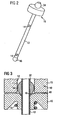
- the armature 16 has a front surface 48 which faces away from the fluid outlet portion 44 and which faces the inlet tube 15 ( Figure 3 with an enlarged distance between the armature 16 and the inlet tube 15 for a better representation).
- the front surface 48 of the armature 16 which faces the inlet tube 15 has a surface layer comprising chromium which enables a curing of the armature 16.
- the fluid is led from the fluid inlet portion 42 in the inlet tube 15 to the hollow valve needle 13 and then through the orifices 14 in the valve needle 13 to the fluid outlet portion 44 near the injection nozzle 30.
- the main spring 22 forces the valve needle 13 in axial direction towards the set body 28. It is depending on the force balance between the force on the valve needle 13 caused by the actuator unit 6 and the force on the valve needle 13 caused by the main spring 22 whether the valve needle 13 is in its closing position or not.
- the actuator unit 6 In the case when the actuator unit 6 is de-energized, the actuator unit 6 does not exert a force on the valve needle 13, and the main spring 22 can exert a force on the guide element 34 and the valve needle 13.
- the valve needle 13 can move in axial direction in its closing position, and the seat part 46 of the valve needle 13 is forced to sealingly rest on the needle seat 26 of the seat body 28.
- the armature spring 19 reduces the velocity of the movement of the armature 16. Consequently, as the guide element 34 is directly coupled to the armature 16, the velocity of the movement of the valve needle 13 in axial direction towards the seat body 28 is also reduced.
- the valve needle 13 is guided very well inside the inlet tube 15 with a minimum of friction and abrasion of the ball-shaped guide element 34 and/or the inlet tube 15. In the closing position of the valve needle 13 a fluid flow through the fluid outlet portion 44 and the injection nozzle 30 is prevented.
- the actuator unit 6 may exert a force on the ball-shaped guide element 34 which is transmitted directly to the valve needle 13.
- the force from the armature 16 on the guide element 34 is contrary to the force on the valve needle 13 caused by the main spring 22.
- the valve needle 13 is able to move in axial direction out of the closing position.
- the movement of the armature 16 is limited when the front surface of the armature 16 which faces away from the fluid outlet portion 44 and which faces the inlet tube 15 gets into contact with inlet tube 15. Outside of the closing position of the valve needle 13, there is a gap between the seat body 28 and the seat part 46 of the valve needle 13. This gap enables a fluid flow through the injection nozzle 30.
- the armature 16 has a high degree of freedom with respect to the inlet tube 15 in which the ball-shaped guide element 34 is arranged. Therefore, the armature 16 can be aligned with respect to the inlet tube 15.
- the contact surfaces between the armature 16 and the inlet tube 15 may fit well to each other and a surface deformation of the contact surfaces between the armature 16 and the inlet tube 15 can be prevented. The prevention of a surface deformation is supported by the curing of the surfaces of the armature 16 and the high hardness of the ball-shaped guide element 34.
Landscapes
- Engineering & Computer Science (AREA)
- Chemical & Material Sciences (AREA)
- Combustion & Propulsion (AREA)
- Mechanical Engineering (AREA)
- General Engineering & Computer Science (AREA)
- Physics & Mathematics (AREA)
- Electromagnetism (AREA)
- Fuel-Injection Apparatus (AREA)
Claims (8)
- Ensemble de soupape (4) d'une soupape d'injection (2), l'ensemble de soupape (4) comprenant
un corps de soupape (10) comprenant un axe longitudinal central (L), le corps de soupape (10) ayant une cavité (11) qui comprend une surface de guidage interne (12) dans une zone de guidage du corps de soupape (10), la cavité (11) ayant une partie entrée de fluide (42) et une partie sortie de fluide (44), un pointeau de soupape (13) axialement mobile dans la cavité (11), le pointeau de soupape (13) ayant une surface externe (32) et empêchant un écoulement de fluide à travers la partie sortie de fluide (44) dans une position de fermeture et libérant l'écoulement de fluide à travers la partie sortie de fluide (44) dans d'autres positions, et
un élément de guidage en forme de bille (34) étant agencé dans la cavité (11) de façon coaxiale avec le pointeau de soupape (13) et s'étendant radialement depuis la surface externe (32) du pointeau de soupape (13) vers la surface de guidage interne (12) du corps de soupape (10) et
une unité d'actionnement (6) qui comprend un induit (16) qui est agencé dans la cavité (11) et est mobile par rapport au pointeau de soupape (13) et est conçu pour coopérer mécaniquement avec l'élément de guidage (34). - Ensemble de soupape (4) selon la revendication 1, dans lequel l'élément de guidage (34) est raccordé fixement au pointeau de soupape (13).
- Ensemble de soupape (4) selon la revendication 1 ou 2, dans lequel l'élément de guidage (34) est soudé au pointeau de soupape (13).
- Ensemble de soupape (4) selon l'une des revendications précédentes, dans lequel le corps de soupape (10) comprend un tube d'entrée (15) et la partie entrée de fluide (42) est agencée à l'intérieur du tube d'entrée (15), et la zone de guidage est agencée dans le tube d'entrée (15), l'élément de guidage formant ainsi un élément de guidage supérieur (34) du pointeau de soupape (13).
- Ensemble de soupape (4) selon l'une des revendications précédentes, dans lequel l'induit (16) et l'élément de guidage (34) forment un dispositif d'interverrouillage.
- Ensemble de soupape (4) selon l'une des revendications précédentes, dans lequel l'induit (16) comprend un renfoncement (18) conçu pour recevoir au moins une partie de l'élément de guidage (34).
- Ensemble de soupape (4) selon la revendication 6, dans lequel le renfoncement (18) est partiellement en forme de cône et le renfoncement (18) fait face à l'élément de guidage en forme de bille (34).
- Soupape d'injection (2) comprenant l'ensemble de soupape (4) selon l'une des revendications précédentes.
Priority Applications (1)
| Application Number | Priority Date | Filing Date | Title |
|---|---|---|---|
| EP20090008639 EP2282042B1 (fr) | 2009-07-01 | 2009-07-01 | Ensemble de soupape et soupape d'injection |
Applications Claiming Priority (1)
| Application Number | Priority Date | Filing Date | Title |
|---|---|---|---|
| EP20090008639 EP2282042B1 (fr) | 2009-07-01 | 2009-07-01 | Ensemble de soupape et soupape d'injection |
Publications (2)
| Publication Number | Publication Date |
|---|---|
| EP2282042A1 EP2282042A1 (fr) | 2011-02-09 |
| EP2282042B1 true EP2282042B1 (fr) | 2013-04-03 |
Family
ID=41348375
Family Applications (1)
| Application Number | Title | Priority Date | Filing Date |
|---|---|---|---|
| EP20090008639 Not-in-force EP2282042B1 (fr) | 2009-07-01 | 2009-07-01 | Ensemble de soupape et soupape d'injection |
Country Status (1)
| Country | Link |
|---|---|
| EP (1) | EP2282042B1 (fr) |
Families Citing this family (2)
| Publication number | Priority date | Publication date | Assignee | Title |
|---|---|---|---|---|
| JP6035648B2 (ja) * | 2012-11-05 | 2016-11-30 | 株式会社ケーヒン | 電磁式燃料噴射弁 |
| EP2851551B1 (fr) * | 2013-09-20 | 2016-05-25 | Continental Automotive GmbH | Soupape d'injection de fluide |
Family Cites Families (5)
| Publication number | Priority date | Publication date | Assignee | Title |
|---|---|---|---|---|
| US4494701A (en) | 1982-09-30 | 1985-01-22 | Allied Corporation | Fuel injector |
| DE3641470A1 (de) | 1986-12-04 | 1988-06-16 | Bosch Gmbh Robert | Elektromagnetisch betaetigbares kraftstoffeinspritzventil |
| US5704553A (en) * | 1995-10-30 | 1998-01-06 | Wieczorek; David P. | Compact injector armature valve assembly |
| FR2890122A3 (fr) * | 2005-08-25 | 2007-03-02 | Renault Sas | Injecteur de carburant pour moteur a combustion interne |
| FR2904378A1 (fr) * | 2006-07-26 | 2008-02-01 | Renault Sas | Dispositif d'injection de fluide, notamment de carburant pour un moteur a combustion interne |
-
2009
- 2009-07-01 EP EP20090008639 patent/EP2282042B1/fr not_active Not-in-force
Also Published As
| Publication number | Publication date |
|---|---|
| EP2282042A1 (fr) | 2011-02-09 |
Similar Documents
| Publication | Publication Date | Title |
|---|---|---|
| EP2771562B1 (fr) | Ensemble de soupape pour soupape d'injection et soupape d'injection | |
| EP2436910B1 (fr) | Ensemble de soupape pour soupape d'injection et soupape d'injection | |
| EP2535552B1 (fr) | Ensemble de soupape pour soupape d'injection et soupape d'injection | |
| KR101815435B1 (ko) | 분사 밸브 용 밸브 어셈블리 및 분사 밸브 | |
| EP2148082A1 (fr) | Arrangement de couplage pour une soupape d'injection et soupape d'injection | |
| US20090140079A1 (en) | Valve assembly for an injection valve and injection valve | |
| EP2354528B1 (fr) | Ensemble de soupape et soupape d'injection | |
| EP2837813B1 (fr) | Ensemble de soupape pour soupape d'injection et soupape d'injection | |
| EP2282042B1 (fr) | Ensemble de soupape et soupape d'injection | |
| EP3061963B1 (fr) | Ensemble de soupape avec un élément de guidage | |
| EP1811166B1 (fr) | Ensemble à vanne pour une soupape d'injection et soupape d'injection | |
| EP2378106A1 (fr) | Ensemble de soupape pour soupape d'injection et soupape d'injection | |
| EP3009658B1 (fr) | Injecteur pour injection de fluides | |
| EP2218900B1 (fr) | Ensemble de soupape pour soupape d'injection et soupape d'injection | |
| EP2375051A1 (fr) | Ensemble de soupape pour soupape d'injection et soupape d'injection | |
| EP1816344B1 (fr) | Assemblage de soupape d'injection et soupape d'injection | |
| CN108138734B (zh) | 用于内燃机的流体喷射装置 | |
| JP4584895B2 (ja) | 電磁式燃料噴射弁 | |
| EP2354531A1 (fr) | Ensemble de soupape pour soupape d'injection et soupape d'injection | |
| EP2003331A1 (fr) | Ensemble de vanne pour soupape d'injection, et soupape d'injection | |
| CN110612390A (zh) | 用于计量流体的阀 | |
| EP2067981B1 (fr) | Ensemble de vanne pour soupape d'injection, et soupape d'injection | |
| EP2216542A1 (fr) | Ensemble de soupape pour soupape d'injection et soupape d'injection | |
| EP2426350A1 (fr) | Ensemble de soupape pour soupape d'injection et soupape d'injection | |
| EP2439400A1 (fr) | Ensemble de soupape pour soupape d'injection et soupape d'injection |
Legal Events
| Date | Code | Title | Description |
|---|---|---|---|
| PUAI | Public reference made under article 153(3) epc to a published international application that has entered the european phase |
Free format text: ORIGINAL CODE: 0009012 |
|
| AK | Designated contracting states |
Kind code of ref document: A1 Designated state(s): AT BE BG CH CY CZ DE DK EE ES FI FR GB GR HR HU IE IS IT LI LT LU LV MC MK MT NL NO PL PT RO SE SI SK SM TR |
|
| AX | Request for extension of the european patent |
Extension state: AL BA RS |
|
| 17P | Request for examination filed |
Effective date: 20110809 |
|
| 17Q | First examination report despatched |
Effective date: 20110902 |
|
| GRAP | Despatch of communication of intention to grant a patent |
Free format text: ORIGINAL CODE: EPIDOSNIGR1 |
|
| GRAP | Despatch of communication of intention to grant a patent |
Free format text: ORIGINAL CODE: EPIDOSNIGR1 |
|
| GRAS | Grant fee paid |
Free format text: ORIGINAL CODE: EPIDOSNIGR3 |
|
| GRAA | (expected) grant |
Free format text: ORIGINAL CODE: 0009210 |
|
| AK | Designated contracting states |
Kind code of ref document: B1 Designated state(s): AT BE BG CH CY CZ DE DK EE ES FI FR GB GR HR HU IE IS IT LI LT LU LV MC MK MT NL NO PL PT RO SE SI SK SM TR |
|
| REG | Reference to a national code |
Ref country code: GB Ref legal event code: FG4D |
|
| REG | Reference to a national code |
Ref country code: CH Ref legal event code: EP Ref country code: AT Ref legal event code: REF Ref document number: 604881 Country of ref document: AT Kind code of ref document: T Effective date: 20130415 |
|
| REG | Reference to a national code |
Ref country code: IE Ref legal event code: FG4D |
|
| REG | Reference to a national code |
Ref country code: DE Ref legal event code: R096 Ref document number: 602009014683 Country of ref document: DE Effective date: 20130606 |
|
| REG | Reference to a national code |
Ref country code: AT Ref legal event code: MK05 Ref document number: 604881 Country of ref document: AT Kind code of ref document: T Effective date: 20130403 |
|
| PG25 | Lapsed in a contracting state [announced via postgrant information from national office to epo] |
Ref country code: SI Free format text: LAPSE BECAUSE OF FAILURE TO SUBMIT A TRANSLATION OF THE DESCRIPTION OR TO PAY THE FEE WITHIN THE PRESCRIBED TIME-LIMIT Effective date: 20130403 |
|
| REG | Reference to a national code |
Ref country code: NL Ref legal event code: VDEP Effective date: 20130403 |
|
| REG | Reference to a national code |
Ref country code: LT Ref legal event code: MG4D |
|
| PG25 | Lapsed in a contracting state [announced via postgrant information from national office to epo] |
Ref country code: ES Free format text: LAPSE BECAUSE OF FAILURE TO SUBMIT A TRANSLATION OF THE DESCRIPTION OR TO PAY THE FEE WITHIN THE PRESCRIBED TIME-LIMIT Effective date: 20130714 Ref country code: FI Free format text: LAPSE BECAUSE OF FAILURE TO SUBMIT A TRANSLATION OF THE DESCRIPTION OR TO PAY THE FEE WITHIN THE PRESCRIBED TIME-LIMIT Effective date: 20130403 Ref country code: NO Free format text: LAPSE BECAUSE OF FAILURE TO SUBMIT A TRANSLATION OF THE DESCRIPTION OR TO PAY THE FEE WITHIN THE PRESCRIBED TIME-LIMIT Effective date: 20130703 Ref country code: PT Free format text: LAPSE BECAUSE OF FAILURE TO SUBMIT A TRANSLATION OF THE DESCRIPTION OR TO PAY THE FEE WITHIN THE PRESCRIBED TIME-LIMIT Effective date: 20130805 Ref country code: BE Free format text: LAPSE BECAUSE OF FAILURE TO SUBMIT A TRANSLATION OF THE DESCRIPTION OR TO PAY THE FEE WITHIN THE PRESCRIBED TIME-LIMIT Effective date: 20130403 Ref country code: SE Free format text: LAPSE BECAUSE OF FAILURE TO SUBMIT A TRANSLATION OF THE DESCRIPTION OR TO PAY THE FEE WITHIN THE PRESCRIBED TIME-LIMIT Effective date: 20130403 Ref country code: GR Free format text: LAPSE BECAUSE OF FAILURE TO SUBMIT A TRANSLATION OF THE DESCRIPTION OR TO PAY THE FEE WITHIN THE PRESCRIBED TIME-LIMIT Effective date: 20130704 Ref country code: IS Free format text: LAPSE BECAUSE OF FAILURE TO SUBMIT A TRANSLATION OF THE DESCRIPTION OR TO PAY THE FEE WITHIN THE PRESCRIBED TIME-LIMIT Effective date: 20130803 Ref country code: LT Free format text: LAPSE BECAUSE OF FAILURE TO SUBMIT A TRANSLATION OF THE DESCRIPTION OR TO PAY THE FEE WITHIN THE PRESCRIBED TIME-LIMIT Effective date: 20130403 Ref country code: AT Free format text: LAPSE BECAUSE OF FAILURE TO SUBMIT A TRANSLATION OF THE DESCRIPTION OR TO PAY THE FEE WITHIN THE PRESCRIBED TIME-LIMIT Effective date: 20130403 Ref country code: NL Free format text: LAPSE BECAUSE OF FAILURE TO SUBMIT A TRANSLATION OF THE DESCRIPTION OR TO PAY THE FEE WITHIN THE PRESCRIBED TIME-LIMIT Effective date: 20130403 |
|
| PG25 | Lapsed in a contracting state [announced via postgrant information from national office to epo] |
Ref country code: HR Free format text: LAPSE BECAUSE OF FAILURE TO SUBMIT A TRANSLATION OF THE DESCRIPTION OR TO PAY THE FEE WITHIN THE PRESCRIBED TIME-LIMIT Effective date: 20130403 Ref country code: CY Free format text: LAPSE BECAUSE OF FAILURE TO SUBMIT A TRANSLATION OF THE DESCRIPTION OR TO PAY THE FEE WITHIN THE PRESCRIBED TIME-LIMIT Effective date: 20130403 Ref country code: BG Free format text: LAPSE BECAUSE OF FAILURE TO SUBMIT A TRANSLATION OF THE DESCRIPTION OR TO PAY THE FEE WITHIN THE PRESCRIBED TIME-LIMIT Effective date: 20130703 Ref country code: PL Free format text: LAPSE BECAUSE OF FAILURE TO SUBMIT A TRANSLATION OF THE DESCRIPTION OR TO PAY THE FEE WITHIN THE PRESCRIBED TIME-LIMIT Effective date: 20130403 Ref country code: LV Free format text: LAPSE BECAUSE OF FAILURE TO SUBMIT A TRANSLATION OF THE DESCRIPTION OR TO PAY THE FEE WITHIN THE PRESCRIBED TIME-LIMIT Effective date: 20130403 |
|
| PG25 | Lapsed in a contracting state [announced via postgrant information from national office to epo] |
Ref country code: DK Free format text: LAPSE BECAUSE OF FAILURE TO SUBMIT A TRANSLATION OF THE DESCRIPTION OR TO PAY THE FEE WITHIN THE PRESCRIBED TIME-LIMIT Effective date: 20130403 Ref country code: SK Free format text: LAPSE BECAUSE OF FAILURE TO SUBMIT A TRANSLATION OF THE DESCRIPTION OR TO PAY THE FEE WITHIN THE PRESCRIBED TIME-LIMIT Effective date: 20130403 Ref country code: EE Free format text: LAPSE BECAUSE OF FAILURE TO SUBMIT A TRANSLATION OF THE DESCRIPTION OR TO PAY THE FEE WITHIN THE PRESCRIBED TIME-LIMIT Effective date: 20130403 Ref country code: CZ Free format text: LAPSE BECAUSE OF FAILURE TO SUBMIT A TRANSLATION OF THE DESCRIPTION OR TO PAY THE FEE WITHIN THE PRESCRIBED TIME-LIMIT Effective date: 20130403 |
|
| PLBE | No opposition filed within time limit |
Free format text: ORIGINAL CODE: 0009261 |
|
| STAA | Information on the status of an ep patent application or granted ep patent |
Free format text: STATUS: NO OPPOSITION FILED WITHIN TIME LIMIT |
|
| PG25 | Lapsed in a contracting state [announced via postgrant information from national office to epo] |
Ref country code: MC Free format text: LAPSE BECAUSE OF FAILURE TO SUBMIT A TRANSLATION OF THE DESCRIPTION OR TO PAY THE FEE WITHIN THE PRESCRIBED TIME-LIMIT Effective date: 20130403 Ref country code: RO Free format text: LAPSE BECAUSE OF FAILURE TO SUBMIT A TRANSLATION OF THE DESCRIPTION OR TO PAY THE FEE WITHIN THE PRESCRIBED TIME-LIMIT Effective date: 20130403 |
|
| REG | Reference to a national code |
Ref country code: CH Ref legal event code: PL |
|
| 26N | No opposition filed |
Effective date: 20140106 |
|
| REG | Reference to a national code |
Ref country code: DE Ref legal event code: R097 Ref document number: 602009014683 Country of ref document: DE Effective date: 20140106 |
|
| REG | Reference to a national code |
Ref country code: IE Ref legal event code: MM4A |
|
| PG25 | Lapsed in a contracting state [announced via postgrant information from national office to epo] |
Ref country code: CH Free format text: LAPSE BECAUSE OF NON-PAYMENT OF DUE FEES Effective date: 20130731 Ref country code: LI Free format text: LAPSE BECAUSE OF NON-PAYMENT OF DUE FEES Effective date: 20130731 |
|
| PG25 | Lapsed in a contracting state [announced via postgrant information from national office to epo] |
Ref country code: IE Free format text: LAPSE BECAUSE OF NON-PAYMENT OF DUE FEES Effective date: 20130701 |
|
| PG25 | Lapsed in a contracting state [announced via postgrant information from national office to epo] |
Ref country code: SM Free format text: LAPSE BECAUSE OF FAILURE TO SUBMIT A TRANSLATION OF THE DESCRIPTION OR TO PAY THE FEE WITHIN THE PRESCRIBED TIME-LIMIT Effective date: 20130403 |
|
| PG25 | Lapsed in a contracting state [announced via postgrant information from national office to epo] |
Ref country code: TR Free format text: LAPSE BECAUSE OF FAILURE TO SUBMIT A TRANSLATION OF THE DESCRIPTION OR TO PAY THE FEE WITHIN THE PRESCRIBED TIME-LIMIT Effective date: 20130403 Ref country code: MT Free format text: LAPSE BECAUSE OF FAILURE TO SUBMIT A TRANSLATION OF THE DESCRIPTION OR TO PAY THE FEE WITHIN THE PRESCRIBED TIME-LIMIT Effective date: 20130403 |
|
| PG25 | Lapsed in a contracting state [announced via postgrant information from national office to epo] |
Ref country code: MK Free format text: LAPSE BECAUSE OF FAILURE TO SUBMIT A TRANSLATION OF THE DESCRIPTION OR TO PAY THE FEE WITHIN THE PRESCRIBED TIME-LIMIT Effective date: 20130403 Ref country code: LU Free format text: LAPSE BECAUSE OF NON-PAYMENT OF DUE FEES Effective date: 20130701 Ref country code: HU Free format text: LAPSE BECAUSE OF FAILURE TO SUBMIT A TRANSLATION OF THE DESCRIPTION OR TO PAY THE FEE WITHIN THE PRESCRIBED TIME-LIMIT; INVALID AB INITIO Effective date: 20090701 |
|
| REG | Reference to a national code |
Ref country code: FR Ref legal event code: PLFP Year of fee payment: 8 |
|
| REG | Reference to a national code |
Ref country code: FR Ref legal event code: PLFP Year of fee payment: 9 |
|
| REG | Reference to a national code |
Ref country code: FR Ref legal event code: PLFP Year of fee payment: 10 |
|
| PGFP | Annual fee paid to national office [announced via postgrant information from national office to epo] |
Ref country code: DE Payment date: 20180731 Year of fee payment: 10 Ref country code: FR Payment date: 20180725 Year of fee payment: 10 Ref country code: IT Payment date: 20180724 Year of fee payment: 10 |
|
| PGFP | Annual fee paid to national office [announced via postgrant information from national office to epo] |
Ref country code: GB Payment date: 20180719 Year of fee payment: 10 |
|
| REG | Reference to a national code |
Ref country code: DE Ref legal event code: R119 Ref document number: 602009014683 Country of ref document: DE |
|
| GBPC | Gb: european patent ceased through non-payment of renewal fee |
Effective date: 20190701 |
|
| PG25 | Lapsed in a contracting state [announced via postgrant information from national office to epo] |
Ref country code: DE Free format text: LAPSE BECAUSE OF NON-PAYMENT OF DUE FEES Effective date: 20200201 Ref country code: GB Free format text: LAPSE BECAUSE OF NON-PAYMENT OF DUE FEES Effective date: 20190701 |
|
| PG25 | Lapsed in a contracting state [announced via postgrant information from national office to epo] |
Ref country code: FR Free format text: LAPSE BECAUSE OF NON-PAYMENT OF DUE FEES Effective date: 20190731 |
|
| PG25 | Lapsed in a contracting state [announced via postgrant information from national office to epo] |
Ref country code: IT Free format text: LAPSE BECAUSE OF NON-PAYMENT OF DUE FEES Effective date: 20190701 |