EP2282012A1 - Guide vane of a gas turbine and method for replacing a cover plate of a guide vane of a gas turbine - Google Patents
Guide vane of a gas turbine and method for replacing a cover plate of a guide vane of a gas turbine Download PDFInfo
- Publication number
- EP2282012A1 EP2282012A1 EP09164551A EP09164551A EP2282012A1 EP 2282012 A1 EP2282012 A1 EP 2282012A1 EP 09164551 A EP09164551 A EP 09164551A EP 09164551 A EP09164551 A EP 09164551A EP 2282012 A1 EP2282012 A1 EP 2282012A1
- Authority
- EP
- European Patent Office
- Prior art keywords
- cover plate
- guide vane
- gas turbine
- housing
- inner platform
- Prior art date
- Legal status (The legal status is an assumption and is not a legal conclusion. Google has not performed a legal analysis and makes no representation as to the accuracy of the status listed.)
- Granted
Links
- 238000000034 method Methods 0.000 title claims abstract description 15
- 238000005520 cutting process Methods 0.000 claims abstract description 4
- 238000002485 combustion reaction Methods 0.000 claims description 3
- 239000007789 gas Substances 0.000 description 17
- 238000005219 brazing Methods 0.000 description 5
- 239000000463 material Substances 0.000 description 5
- 238000001816 cooling Methods 0.000 description 4
- 238000003801 milling Methods 0.000 description 3
- 239000012809 cooling fluid Substances 0.000 description 1
- 238000010438 heat treatment Methods 0.000 description 1
- 238000004519 manufacturing process Methods 0.000 description 1
- 239000000155 melt Substances 0.000 description 1
- 238000002844 melting Methods 0.000 description 1
- 230000008018 melting Effects 0.000 description 1
- 238000012986 modification Methods 0.000 description 1
- 230000004048 modification Effects 0.000 description 1
Images

Classifications
-
- F—MECHANICAL ENGINEERING; LIGHTING; HEATING; WEAPONS; BLASTING
- F01—MACHINES OR ENGINES IN GENERAL; ENGINE PLANTS IN GENERAL; STEAM ENGINES
- F01D—NON-POSITIVE DISPLACEMENT MACHINES OR ENGINES, e.g. STEAM TURBINES
- F01D9/00—Stators
- F01D9/02—Nozzles; Nozzle boxes; Stator blades; Guide conduits, e.g. individual nozzles
-
- F—MECHANICAL ENGINEERING; LIGHTING; HEATING; WEAPONS; BLASTING
- F01—MACHINES OR ENGINES IN GENERAL; ENGINE PLANTS IN GENERAL; STEAM ENGINES
- F01D—NON-POSITIVE DISPLACEMENT MACHINES OR ENGINES, e.g. STEAM TURBINES
- F01D5/00—Blades; Blade-carrying members; Heating, heat-insulating, cooling or antivibration means on the blades or the members
- F01D5/005—Repairing methods or devices
-
- F—MECHANICAL ENGINEERING; LIGHTING; HEATING; WEAPONS; BLASTING
- F05—INDEXING SCHEMES RELATING TO ENGINES OR PUMPS IN VARIOUS SUBCLASSES OF CLASSES F01-F04
- F05D—INDEXING SCHEME FOR ASPECTS RELATING TO NON-POSITIVE-DISPLACEMENT MACHINES OR ENGINES, GAS-TURBINES OR JET-PROPULSION PLANTS
- F05D2240/00—Components
- F05D2240/80—Platforms for stationary or moving blades
-
- Y—GENERAL TAGGING OF NEW TECHNOLOGICAL DEVELOPMENTS; GENERAL TAGGING OF CROSS-SECTIONAL TECHNOLOGIES SPANNING OVER SEVERAL SECTIONS OF THE IPC; TECHNICAL SUBJECTS COVERED BY FORMER USPC CROSS-REFERENCE ART COLLECTIONS [XRACs] AND DIGESTS
- Y10—TECHNICAL SUBJECTS COVERED BY FORMER USPC
- Y10T—TECHNICAL SUBJECTS COVERED BY FORMER US CLASSIFICATION
- Y10T29/00—Metal working
- Y10T29/49—Method of mechanical manufacture
- Y10T29/49316—Impeller making
- Y10T29/49318—Repairing or disassembling
Definitions
- the present invention relates to a guide vane of a gas turbine and a method for replacing a cover plate of a guide vane of a gas turbine.
- Guide vanes are known to comprise blades that have one end with an outer platform connected to a guide vane carrier or gas turbine casing, and an opposite end provided with an inner platform facing the rotor.
- guide vanes in order to withstand the high temperature of the hot gases flowing in the hot gases path, guide vanes (and in particular those closest to the combustion chamber) have an inner cooling circuit.
- This inner cooling circuit comprises a path that makes a cooling fluid (typically compressed air) to circulate within the guide vanes and be ejected into the hot gases path through cooling holes provided over the guide vanes.
- a cooling fluid typically compressed air
- the guide vanes have apertures at both the outer and inner platform; the inner platform is then closed by a cover plate.
- the inner platform has a housing with L-shaped sides, such that the cover plate is inserted in the housing with the terminal portions of the L-shaped sides that withhold it; then the cover plate is also connected (usually brazed) to the platform.
- cover plates Periodically the cover plates must be removed from the housing to be reconditioned; after the cover plates are removed, new or the same cover plates (after reconditioning) must be connected in the housing of the inner platform.
- the brazing connection is not as reliable as the mechanical connection and in some cases could break.
- the technical aim of the present invention is therefore to provide a guide vane of a gas turbine and method for replacing a cover plate of a guide vane of a gas turbine by which the said problems of the known art are eliminated.
- an object of the invention is to provide a guide vane and a method with which the connection between the inner platform and the cover plate even after the reconditioning operations is very reliable.
- Another object of the invention is to provide a method which enable the cover plate of an inner platform of a guide vane be replaced without substantially impairing the mechanical withholding of the cover plate into the housing.
- the guide vane 1 comprises a blade 2 having an outer platform 3 connected to a guide vane carrier or gas turbine casing 4.
- the guide vane 2 has an inner platform 5 that carries an impingement plate 6 and a cover plate 7.
- the cover plate 7 is connected to a honeycomb 9 and a seal 10 that faces a rotor 11.
- the inner platform 5 has a dovetail housing 13 to which the cover plate 7 is connected.
- the dovetail housing 13 has sides tilted by an angle A being 50-70° with respect to an axis 14 parallel to the gas turbine axis 15, preferably 56-64° and more preferably about 60°.
- the guide vane of the invention is the first or second guide vane after a combustion chamber of the gas turbine.
- the present invention also refers to a method for replacing a cover plate of a guide vane of a gas turbine.
- the method is implemented with a guide vane 1 having the structure above described with the inner platform 5 that has a dovetail housing 13 for holding the cover plate 7.
- the method consists in separating the cover plate 7 from the inner platform 5 by cutting (typically by milling) along the profile of the dovetail housing 13.
- figure 3 schematically shows an end of the platform 5 defining the housing 13 with a portion of the cover plate 7.
- Figure 3 also shows a cut 16 made by milling (in particular figure 3 only shows one end of the platform, but the cut at the other end is substantially similar to that shown).
- a new or refurbished cover plate 7 (the same or a different refurbished cover plate 7) is inserted into the housing 13; also in this case, the new or refurbished cover plate is made to slide into the housing 13.
- the cut 16 is made in the platform 5 (as shown in figure 3 ) even if in further embodiments it may also be cut partly in the cover plate 7 and partly in the platform 5.
Abstract
Description
- The present invention relates to a guide vane of a gas turbine and a method for replacing a cover plate of a guide vane of a gas turbine.
- Guide vanes are known to comprise blades that have one end with an outer platform connected to a guide vane carrier or gas turbine casing, and an opposite end provided with an inner platform facing the rotor.
- Moreover, in order to withstand the high temperature of the hot gases flowing in the hot gases path, guide vanes (and in particular those closest to the combustion chamber) have an inner cooling circuit.
- This inner cooling circuit comprises a path that makes a cooling fluid (typically compressed air) to circulate within the guide vanes and be ejected into the hot gases path through cooling holes provided over the guide vanes.
- For manufacturing reasons (otherwise it would not be possible for example to realise the cooling circuit), the guide vanes have apertures at both the outer and inner platform; the inner platform is then closed by a cover plate.
- Traditionally, the inner platform has a housing with L-shaped sides, such that the cover plate is inserted in the housing with the terminal portions of the L-shaped sides that withhold it; then the cover plate is also connected (usually brazed) to the platform.
- Periodically the cover plates must be removed from the housing to be reconditioned; after the cover plates are removed, new or the same cover plates (after reconditioning) must be connected in the housing of the inner platform.
- Nevertheless, removal of the cover plates is carried out by milling the L-shaped sides of the housing.
- Thus, when the cover plates are re-inserted into the housing, they are only brazed thereto, but there is no mechanical withholding due to the L-shaped sides of the housing.
- The brazing connection is not as reliable as the mechanical connection and in some cases could break.
- The technical aim of the present invention is therefore to provide a guide vane of a gas turbine and method for replacing a cover plate of a guide vane of a gas turbine by which the said problems of the known art are eliminated.
- Within the scope of this technical aim, an object of the invention is to provide a guide vane and a method with which the connection between the inner platform and the cover plate even after the reconditioning operations is very reliable.
- Another object of the invention is to provide a method which enable the cover plate of an inner platform of a guide vane be replaced without substantially impairing the mechanical withholding of the cover plate into the housing.
- The technical aim, together with these and further objects, are attained according to the invention by providing a guide vane of a gas turbine and method for replacing a cover plate of a guide vane of a gas turbine in accordance with the accompanying claims.
- Further characteristics and advantages of the invention will be more apparent from the description of a preferred but non-exclusive embodiment of the guide vane and method according to the invention, illustrated by way of non-limiting example in the accompanying drawings, in which:
-
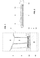
Figure 1 is a schematic partial cross section of a guide vane according to the invention; -
Figure 2 is an enlarged inner platform offigure 1 ; -
Figure 3 is a further enlarged portion offigure 2 ; and -
Figure 4 shows a portion of a dovetail housing with a new or refurbished cover plate inserted thereinto. - With reference to the figures, these show a guide vane of a gas turbine generally indicated by the
reference 1. - The
guide vane 1 comprises a blade 2 having an outer platform 3 connected to a guide vane carrier orgas turbine casing 4. - At the opposite end, the guide vane 2 has an
inner platform 5 that carries animpingement plate 6 and a cover plate 7. - The cover plate 7 is connected to a honeycomb 9 and a seal 10 that faces a
rotor 11. - The
inner platform 5 has adovetail housing 13 to which the cover plate 7 is connected. - In particular the
dovetail housing 13 has sides tilted by an angle A being 50-70° with respect to anaxis 14 parallel to thegas turbine axis 15, preferably 56-64° and more preferably about 60°. - Moreover, preferably the guide vane of the invention is the first or second guide vane after a combustion chamber of the gas turbine.
- The present invention also refers to a method for replacing a cover plate of a guide vane of a gas turbine.
- In particular the method is implemented with a
guide vane 1 having the structure above described with theinner platform 5 that has adovetail housing 13 for holding the cover plate 7. - The method consists in separating the cover plate 7 from the
inner platform 5 by cutting (typically by milling) along the profile of thedovetail housing 13. - In this respect,
figure 3 schematically shows an end of theplatform 5 defining thehousing 13 with a portion of the cover plate 7. -
Figure 3 also shows acut 16 made by milling (in particularfigure 3 only shows one end of the platform, but the cut at the other end is substantially similar to that shown). - After a
cut 16 at each end of thehousing 13 is made (and thus the cover plate 7 is separated from the inner platform 5), the cover plate is made to slide out of thehousing 13. - Afterwards a new or refurbished cover plate 7 (the same or a different refurbished cover plate 7) is inserted into the
housing 13; also in this case, the new or refurbished cover plate is made to slide into thehousing 13. - Typically, after the new or refurbished cover plate 7 has been inserted in the
housing 13, it is brazed to theinner platform 5. - For example this could be achieved by providing a brazing material 17 between the cover plate 7 and the inner platform 5 (along the sides of the housing 13) and when the cover plate 7 is inside of the
housing 13, by heating theguide vane 1 in an oven, such that the brazing material melts (naturally the melting temperature of the brazing material must be greater than the working temperatures of the guide vane). - The
cut 16 is made in the platform 5 (as shown infigure 3 ) even if in further embodiments it may also be cut partly in the cover plate 7 and partly in theplatform 5. - The guide vane and the method conceived in this manner are susceptible to numerous modifications and variants, all falling within the scope of the inventive concept; moreover all details can be replaced by technically equivalent elements.
- In practice the materials used and the dimensions can be chosen at will according to requirements and to the state of the art.
-
- 1
- guide vane
- 2
- blade
- 3
- outer platform
- 4
- guide vane carrier or gas turbine casing
- 5
- inner platform
- 6
- impingement plate
- 7
- cover plate
- 9
- honeycomb
- 10
- seal
- 11
- rotor
- 13
- dovetail housing
- 14
- axis
- 15
- gas turbine axis
- 16
- cut
- 17
- brazing material
- A
- angle of the dovetail housing sides
Claims (6)
- Guide vane (1) of a gas turbine comprising a blade (2) having an outer platform (3) connectable to a guide vane carrier or gas turbine casing (4), and at the opposite end an inner platform (5) that carries a cover plate (7), characterised in that the inner platform (5) has a dovetail housing (13) to which said cover plate (7) is connected.
- Guide vane (1) as claimed in claim 1, characterised in that said dovetail housing (13) has sides tilted by 50-70° with respect to an axis (14) parallel to the gas turbine axis (15), preferably 56-64° and more preferably about 60°.
- Guide vane (1) as claimed in claim 1, characterised by being the first or second guide vane after a combustion chamber of the gas turbine.
- Method for replacing a cover plate (7) of a guide vane (1) of a gas turbine comprising a blade (2) having an outer platform (3) connectable to a guide vane carrier or gas turbine casing (4) and at the opposite end an inner platform (5) that carries a cover plate (7), wherein the inner platform (5) has a dovetail housing (13) to which said cover plate (7) is connected, characterised by separating the cover plate (7) from the inner platform (5) by cutting along the profile of the dovetail housing (13), then making the cover plate (7) to slide out of the dovetail housing (13), thus inserting a new or refurbished cover plate (7) into the dovetail housing (13).
- Method as claimed in claim 4, characterised in that after the new or refurbished cover plate (7) has been inserted in the housing, it is brazed to the inner platform (5).
- Method as claimed in claim 4, characterised in that cutting is carried out at least partially in the inner platform (5).
Priority Applications (3)
| Application Number | Priority Date | Filing Date | Title |
|---|---|---|---|
| ES09164551.5T ES2561037T3 (en) | 2009-07-03 | 2009-07-03 | Method of replacing a cover of a guide blade of a gas turbine |
| EP09164551.5A EP2282012B1 (en) | 2009-07-03 | 2009-07-03 | Method for replacing a cover plate of a guide vane of a gas turbine |
| US12/827,696 US8727720B2 (en) | 2009-07-03 | 2010-06-30 | Guide vane of a gas turbine and method for replacing a cover plate of a guide vane of a gas turbine |
Applications Claiming Priority (1)
| Application Number | Priority Date | Filing Date | Title |
|---|---|---|---|
| EP09164551.5A EP2282012B1 (en) | 2009-07-03 | 2009-07-03 | Method for replacing a cover plate of a guide vane of a gas turbine |
Publications (2)
| Publication Number | Publication Date |
|---|---|
| EP2282012A1 true EP2282012A1 (en) | 2011-02-09 |
| EP2282012B1 EP2282012B1 (en) | 2015-11-25 |
Family
ID=41228236
Family Applications (1)
| Application Number | Title | Priority Date | Filing Date |
|---|---|---|---|
| EP09164551.5A Active EP2282012B1 (en) | 2009-07-03 | 2009-07-03 | Method for replacing a cover plate of a guide vane of a gas turbine |
Country Status (3)
| Country | Link |
|---|---|
| US (1) | US8727720B2 (en) |
| EP (1) | EP2282012B1 (en) |
| ES (1) | ES2561037T3 (en) |
Cited By (2)
| Publication number | Priority date | Publication date | Assignee | Title |
|---|---|---|---|---|
| US9988906B2 (en) | 2013-02-08 | 2018-06-05 | General Electric Company | Turbomachine rotor blade milling machine system and method of field repairing a turbomachine rotor blade |
| EP3361054A4 (en) * | 2015-11-27 | 2018-12-12 | Mitsubishi Hitachi Power Systems, Ltd. | Flow path forming plate, stator vane and flow path forming member provided with flow path forming plate, gas turbine, method of manufacturing flow path forming plate, and method of remodeling flow path forming plate |
Families Citing this family (9)
| Publication number | Priority date | Publication date | Assignee | Title |
|---|---|---|---|---|
| US9011079B2 (en) | 2012-01-09 | 2015-04-21 | General Electric Company | Turbine nozzle compartmentalized cooling system |
| US8944751B2 (en) | 2012-01-09 | 2015-02-03 | General Electric Company | Turbine nozzle cooling assembly |
| US9011078B2 (en) | 2012-01-09 | 2015-04-21 | General Electric Company | Turbine vane seal carrier with slots for cooling and assembly |
| US8864445B2 (en) | 2012-01-09 | 2014-10-21 | General Electric Company | Turbine nozzle assembly methods |
| US9133724B2 (en) | 2012-01-09 | 2015-09-15 | General Electric Company | Turbomachine component including a cover plate |
| US9039350B2 (en) | 2012-01-09 | 2015-05-26 | General Electric Company | Impingement cooling system for use with contoured surfaces |
| US9206700B2 (en) * | 2013-10-25 | 2015-12-08 | Siemens Aktiengesellschaft | Outer vane support ring including a strong back plate in a compressor section of a gas turbine engine |
| EP2998517B1 (en) * | 2014-09-16 | 2019-03-27 | Ansaldo Energia Switzerland AG | Sealing arrangement at the interface between a combustor and a turbine of a gas turbine and gas turbine with such a sealing arrangement |
| US9511452B2 (en) * | 2015-02-09 | 2016-12-06 | United Technologies Corporation | Assemblies with brazed joints and methods of fabricating assemblies with brazed joints |
Citations (4)
| Publication number | Priority date | Publication date | Assignee | Title |
|---|---|---|---|---|
| EP0384166A2 (en) * | 1989-02-21 | 1990-08-29 | Westinghouse Electric Corporation | Compressor diaphragm assembly |
| US6773229B1 (en) * | 2003-03-14 | 2004-08-10 | General Electric Company | Turbine nozzle having angel wing seal lands and associated welding method |
| EP1843009A1 (en) * | 2006-04-06 | 2007-10-10 | Siemens Aktiengesellschaft | Stator vane segment for a turbomachine, associated manufacturing method and turbomachine |
| WO2009001415A1 (en) * | 2007-06-22 | 2008-12-31 | Mitsubishi Heavy Industries, Ltd. | Stator blade ring and axial flow compressor using the same |
-
2009
- 2009-07-03 ES ES09164551.5T patent/ES2561037T3/en active Active
- 2009-07-03 EP EP09164551.5A patent/EP2282012B1/en active Active
-
2010
- 2010-06-30 US US12/827,696 patent/US8727720B2/en not_active Expired - Fee Related
Patent Citations (4)
| Publication number | Priority date | Publication date | Assignee | Title |
|---|---|---|---|---|
| EP0384166A2 (en) * | 1989-02-21 | 1990-08-29 | Westinghouse Electric Corporation | Compressor diaphragm assembly |
| US6773229B1 (en) * | 2003-03-14 | 2004-08-10 | General Electric Company | Turbine nozzle having angel wing seal lands and associated welding method |
| EP1843009A1 (en) * | 2006-04-06 | 2007-10-10 | Siemens Aktiengesellschaft | Stator vane segment for a turbomachine, associated manufacturing method and turbomachine |
| WO2009001415A1 (en) * | 2007-06-22 | 2008-12-31 | Mitsubishi Heavy Industries, Ltd. | Stator blade ring and axial flow compressor using the same |
Cited By (3)
| Publication number | Priority date | Publication date | Assignee | Title |
|---|---|---|---|---|
| US9988906B2 (en) | 2013-02-08 | 2018-06-05 | General Electric Company | Turbomachine rotor blade milling machine system and method of field repairing a turbomachine rotor blade |
| EP3361054A4 (en) * | 2015-11-27 | 2018-12-12 | Mitsubishi Hitachi Power Systems, Ltd. | Flow path forming plate, stator vane and flow path forming member provided with flow path forming plate, gas turbine, method of manufacturing flow path forming plate, and method of remodeling flow path forming plate |
| US10704394B2 (en) | 2015-11-27 | 2020-07-07 | Mitsubishi Hitachi Power Systems, Ltd. | Flow passage forming plate, flow passage forming member assembly and vane including the same, gas turbine, manufacturing method of flow passage forming plate, and modification method of flow passage forming plate |
Also Published As
| Publication number | Publication date |
|---|---|
| EP2282012B1 (en) | 2015-11-25 |
| US8727720B2 (en) | 2014-05-20 |
| US20110014054A1 (en) | 2011-01-20 |
| ES2561037T3 (en) | 2016-02-24 |
Similar Documents
| Publication | Publication Date | Title |
|---|---|---|
| US8727720B2 (en) | Guide vane of a gas turbine and method for replacing a cover plate of a guide vane of a gas turbine | |
| CN102042045B (en) | Shroud assembly with discourager | |
| EP2093376B1 (en) | A turbine vane segment, the corresponding nozzle assembly and method of cooling this vane | |
| CN102128059B (en) | Turbine nozzle assembly | |
| JP4948797B2 (en) | Method and apparatus for cooling a gas turbine engine rotor blade | |
| EP2226128B1 (en) | Method of coating a shield for a component | |
| CN102102542B (en) | Turbine blade | |
| US7600966B2 (en) | Turbine airfoil with improved cooling | |
| EP2295722B1 (en) | Blade of a turbine | |
| US20070189896A1 (en) | Methods and apparatus for cooling gas turbine rotor blades | |
| EP1674665B1 (en) | Turbine nozzle segment and method of repairing the same | |
| EP2060745B1 (en) | Gas turbine sealing segment | |
| JP6405102B2 (en) | Turbine airfoil assembly | |
| US20180230832A1 (en) | Cooled blisk for gas turbine engine | |
| EP1748155B1 (en) | Cooled shroud assembly and method of cooling a shroud | |
| PL202702B1 (en) | Turbine nozzle segment, method of repairing a such nozzle segment and replacement casting for use in repairing the turbine nozzle segments | |
| CA2672806A1 (en) | Shrouded rotor blade with outer plenum and method of fabricating the same | |
| CN102465717A (en) | Turbomachine vane and method of cooling a turbomachine vane | |
| CN105283639B (en) | Turbine components with stress elimination chamber | |
| EP2540972A1 (en) | Blade for a gas turbine and method for producing such a blade | |
| EP3176373A1 (en) | Turbomachine blade with generally radial cooling conduit to wheel space | |
| CN102650222B (en) | Turbine shroud and the method for the manufacture of turbine shroud | |
| US20180179899A1 (en) | Method and apparatus for brazed engine components | |
| EP3179052A1 (en) | Anti-corner-leakage seal in gas turbine | |
| EP1541809B1 (en) | Turbine nozzle guide vane and corresponding method of forming |
Legal Events
| Date | Code | Title | Description |
|---|---|---|---|
| PUAI | Public reference made under article 153(3) epc to a published international application that has entered the european phase |
Free format text: ORIGINAL CODE: 0009012 |
|
| AK | Designated contracting states |
Kind code of ref document: A1 Designated state(s): AT BE BG CH CY CZ DE DK EE ES FI FR GB GR HR HU IE IS IT LI LT LU LV MC MK MT NL NO PL PT RO SE SI SK SM TR |
|
| AX | Request for extension of the european patent |
Extension state: AL BA RS |
|
| 17P | Request for examination filed |
Effective date: 20110802 |
|
| 17Q | First examination report despatched |
Effective date: 20110824 |
|
| GRAP | Despatch of communication of intention to grant a patent |
Free format text: ORIGINAL CODE: EPIDOSNIGR1 |
|
| INTG | Intention to grant announced |
Effective date: 20150617 |
|
| GRAS | Grant fee paid |
Free format text: ORIGINAL CODE: EPIDOSNIGR3 |
|
| GRAA | (expected) grant |
Free format text: ORIGINAL CODE: 0009210 |
|
| AK | Designated contracting states |
Kind code of ref document: B1 Designated state(s): AT BE BG CH CY CZ DE DK EE ES FI FR GB GR HR HU IE IS IT LI LT LU LV MC MK MT NL NO PL PT RO SE SI SK SM TR |
|
| REG | Reference to a national code |
Ref country code: GB Ref legal event code: FG4D |
|
| REG | Reference to a national code |
Ref country code: CH Ref legal event code: EP |
|
| REG | Reference to a national code |
Ref country code: AT Ref legal event code: REF Ref document number: 762726 Country of ref document: AT Kind code of ref document: T Effective date: 20151215 |
|
| REG | Reference to a national code |
Ref country code: IE Ref legal event code: FG4D |
|
| REG | Reference to a national code |
Ref country code: DE Ref legal event code: R096 Ref document number: 602009034927 Country of ref document: DE |
|
| REG | Reference to a national code |
Ref country code: ES Ref legal event code: FG2A Ref document number: 2561037 Country of ref document: ES Kind code of ref document: T3 Effective date: 20160224 |
|
| REG | Reference to a national code |
Ref country code: LT Ref legal event code: MG4D |
|
| REG | Reference to a national code |
Ref country code: NL Ref legal event code: MP Effective date: 20160225 |
|
| REG | Reference to a national code |
Ref country code: AT Ref legal event code: MK05 Ref document number: 762726 Country of ref document: AT Kind code of ref document: T Effective date: 20151125 |
|
| PG25 | Lapsed in a contracting state [announced via postgrant information from national office to epo] |
Ref country code: LT Free format text: LAPSE BECAUSE OF FAILURE TO SUBMIT A TRANSLATION OF THE DESCRIPTION OR TO PAY THE FEE WITHIN THE PRESCRIBED TIME-LIMIT Effective date: 20151125 Ref country code: IS Free format text: LAPSE BECAUSE OF FAILURE TO SUBMIT A TRANSLATION OF THE DESCRIPTION OR TO PAY THE FEE WITHIN THE PRESCRIBED TIME-LIMIT Effective date: 20160325 Ref country code: NO Free format text: LAPSE BECAUSE OF FAILURE TO SUBMIT A TRANSLATION OF THE DESCRIPTION OR TO PAY THE FEE WITHIN THE PRESCRIBED TIME-LIMIT Effective date: 20160225 Ref country code: NL Free format text: LAPSE BECAUSE OF FAILURE TO SUBMIT A TRANSLATION OF THE DESCRIPTION OR TO PAY THE FEE WITHIN THE PRESCRIBED TIME-LIMIT Effective date: 20151125 Ref country code: HR Free format text: LAPSE BECAUSE OF FAILURE TO SUBMIT A TRANSLATION OF THE DESCRIPTION OR TO PAY THE FEE WITHIN THE PRESCRIBED TIME-LIMIT Effective date: 20151125 |
|
| PG25 | Lapsed in a contracting state [announced via postgrant information from national office to epo] |
Ref country code: GR Free format text: LAPSE BECAUSE OF FAILURE TO SUBMIT A TRANSLATION OF THE DESCRIPTION OR TO PAY THE FEE WITHIN THE PRESCRIBED TIME-LIMIT Effective date: 20160226 Ref country code: AT Free format text: LAPSE BECAUSE OF FAILURE TO SUBMIT A TRANSLATION OF THE DESCRIPTION OR TO PAY THE FEE WITHIN THE PRESCRIBED TIME-LIMIT Effective date: 20151125 Ref country code: LV Free format text: LAPSE BECAUSE OF FAILURE TO SUBMIT A TRANSLATION OF THE DESCRIPTION OR TO PAY THE FEE WITHIN THE PRESCRIBED TIME-LIMIT Effective date: 20151125 Ref country code: PT Free format text: LAPSE BECAUSE OF FAILURE TO SUBMIT A TRANSLATION OF THE DESCRIPTION OR TO PAY THE FEE WITHIN THE PRESCRIBED TIME-LIMIT Effective date: 20160325 Ref country code: PL Free format text: LAPSE BECAUSE OF FAILURE TO SUBMIT A TRANSLATION OF THE DESCRIPTION OR TO PAY THE FEE WITHIN THE PRESCRIBED TIME-LIMIT Effective date: 20151125 Ref country code: FI Free format text: LAPSE BECAUSE OF FAILURE TO SUBMIT A TRANSLATION OF THE DESCRIPTION OR TO PAY THE FEE WITHIN THE PRESCRIBED TIME-LIMIT Effective date: 20151125 Ref country code: SE Free format text: LAPSE BECAUSE OF FAILURE TO SUBMIT A TRANSLATION OF THE DESCRIPTION OR TO PAY THE FEE WITHIN THE PRESCRIBED TIME-LIMIT Effective date: 20151125 |
|
| PG25 | Lapsed in a contracting state [announced via postgrant information from national office to epo] |
Ref country code: CZ Free format text: LAPSE BECAUSE OF FAILURE TO SUBMIT A TRANSLATION OF THE DESCRIPTION OR TO PAY THE FEE WITHIN THE PRESCRIBED TIME-LIMIT Effective date: 20151125 |
|
| REG | Reference to a national code |
Ref country code: DE Ref legal event code: R081 Ref document number: 602009034927 Country of ref document: DE Owner name: GENERAL ELECTRIC TECHNOLOGY GMBH, CH Free format text: FORMER OWNER: ALSTOM TECHNOLOGY LTD., BADEN, CH Ref country code: DE Ref legal event code: R081 Ref document number: 602009034927 Country of ref document: DE Owner name: ANSALDO ENERGIA IP UK LIMITED, GB Free format text: FORMER OWNER: ALSTOM TECHNOLOGY LTD., BADEN, CH |
|
| RAP2 | Party data changed (patent owner data changed or rights of a patent transferred) |
Owner name: GENERAL ELECTRIC TECHNOLOGY GMBH |
|
| REG | Reference to a national code |
Ref country code: DE Ref legal event code: R097 Ref document number: 602009034927 Country of ref document: DE |
|
| PG25 | Lapsed in a contracting state [announced via postgrant information from national office to epo] |
Ref country code: RO Free format text: LAPSE BECAUSE OF FAILURE TO SUBMIT A TRANSLATION OF THE DESCRIPTION OR TO PAY THE FEE WITHIN THE PRESCRIBED TIME-LIMIT Effective date: 20151125 Ref country code: SK Free format text: LAPSE BECAUSE OF FAILURE TO SUBMIT A TRANSLATION OF THE DESCRIPTION OR TO PAY THE FEE WITHIN THE PRESCRIBED TIME-LIMIT Effective date: 20151125 Ref country code: DK Free format text: LAPSE BECAUSE OF FAILURE TO SUBMIT A TRANSLATION OF THE DESCRIPTION OR TO PAY THE FEE WITHIN THE PRESCRIBED TIME-LIMIT Effective date: 20151125 Ref country code: SM Free format text: LAPSE BECAUSE OF FAILURE TO SUBMIT A TRANSLATION OF THE DESCRIPTION OR TO PAY THE FEE WITHIN THE PRESCRIBED TIME-LIMIT Effective date: 20151125 Ref country code: EE Free format text: LAPSE BECAUSE OF FAILURE TO SUBMIT A TRANSLATION OF THE DESCRIPTION OR TO PAY THE FEE WITHIN THE PRESCRIBED TIME-LIMIT Effective date: 20151125 |
|
| PLBE | No opposition filed within time limit |
Free format text: ORIGINAL CODE: 0009261 |
|
| STAA | Information on the status of an ep patent application or granted ep patent |
Free format text: STATUS: NO OPPOSITION FILED WITHIN TIME LIMIT |
|
| 26N | No opposition filed |
Effective date: 20160826 |
|
| PG25 | Lapsed in a contracting state [announced via postgrant information from national office to epo] |
Ref country code: SI Free format text: LAPSE BECAUSE OF FAILURE TO SUBMIT A TRANSLATION OF THE DESCRIPTION OR TO PAY THE FEE WITHIN THE PRESCRIBED TIME-LIMIT Effective date: 20151125 |
|
| PG25 | Lapsed in a contracting state [announced via postgrant information from national office to epo] |
Ref country code: BE Free format text: LAPSE BECAUSE OF FAILURE TO SUBMIT A TRANSLATION OF THE DESCRIPTION OR TO PAY THE FEE WITHIN THE PRESCRIBED TIME-LIMIT Effective date: 20151125 |
|
| REG | Reference to a national code |
Ref country code: CH Ref legal event code: PL |
|
| PG25 | Lapsed in a contracting state [announced via postgrant information from national office to epo] |
Ref country code: MC Free format text: LAPSE BECAUSE OF FAILURE TO SUBMIT A TRANSLATION OF THE DESCRIPTION OR TO PAY THE FEE WITHIN THE PRESCRIBED TIME-LIMIT Effective date: 20151125 |
|
| PG25 | Lapsed in a contracting state [announced via postgrant information from national office to epo] |
Ref country code: CH Free format text: LAPSE BECAUSE OF NON-PAYMENT OF DUE FEES Effective date: 20160731 Ref country code: FR Free format text: LAPSE BECAUSE OF NON-PAYMENT OF DUE FEES Effective date: 20160801 Ref country code: LI Free format text: LAPSE BECAUSE OF NON-PAYMENT OF DUE FEES Effective date: 20160731 |
|
| REG | Reference to a national code |
Ref country code: FR Ref legal event code: ST Effective date: 20170331 |
|
| REG | Reference to a national code |
Ref country code: IE Ref legal event code: MM4A |
|
| PG25 | Lapsed in a contracting state [announced via postgrant information from national office to epo] |
Ref country code: IE Free format text: LAPSE BECAUSE OF NON-PAYMENT OF DUE FEES Effective date: 20160703 |
|
| PG25 | Lapsed in a contracting state [announced via postgrant information from national office to epo] |
Ref country code: LU Free format text: LAPSE BECAUSE OF NON-PAYMENT OF DUE FEES Effective date: 20160703 |
|
| REG | Reference to a national code |
Ref country code: DE Ref legal event code: R081 Ref document number: 602009034927 Country of ref document: DE Owner name: ANSALDO ENERGIA IP UK LIMITED, GB Free format text: FORMER OWNER: GENERAL ELECTRIC TECHNOLOGY GMBH, BADEN, CH |
|
| REG | Reference to a national code |
Ref country code: GB Ref legal event code: 732E Free format text: REGISTERED BETWEEN 20170824 AND 20170830 |
|
| REG | Reference to a national code |
Ref country code: ES Ref legal event code: PC2A Owner name: ANSALDO ENERGIA IP UK LIMITED Effective date: 20170927 |
|
| PGFP | Annual fee paid to national office [announced via postgrant information from national office to epo] |
Ref country code: FR Payment date: 20170823 Year of fee payment: 9 |
|
| PG25 | Lapsed in a contracting state [announced via postgrant information from national office to epo] |
Ref country code: HU Free format text: LAPSE BECAUSE OF FAILURE TO SUBMIT A TRANSLATION OF THE DESCRIPTION OR TO PAY THE FEE WITHIN THE PRESCRIBED TIME-LIMIT; INVALID AB INITIO Effective date: 20090703 Ref country code: CY Free format text: LAPSE BECAUSE OF FAILURE TO SUBMIT A TRANSLATION OF THE DESCRIPTION OR TO PAY THE FEE WITHIN THE PRESCRIBED TIME-LIMIT Effective date: 20151125 |
|
| PG25 | Lapsed in a contracting state [announced via postgrant information from national office to epo] |
Ref country code: TR Free format text: LAPSE BECAUSE OF FAILURE TO SUBMIT A TRANSLATION OF THE DESCRIPTION OR TO PAY THE FEE WITHIN THE PRESCRIBED TIME-LIMIT Effective date: 20151125 Ref country code: MT Free format text: LAPSE BECAUSE OF NON-PAYMENT OF DUE FEES Effective date: 20160731 Ref country code: MK Free format text: LAPSE BECAUSE OF FAILURE TO SUBMIT A TRANSLATION OF THE DESCRIPTION OR TO PAY THE FEE WITHIN THE PRESCRIBED TIME-LIMIT Effective date: 20151125 |
|
| PG25 | Lapsed in a contracting state [announced via postgrant information from national office to epo] |
Ref country code: BG Free format text: LAPSE BECAUSE OF FAILURE TO SUBMIT A TRANSLATION OF THE DESCRIPTION OR TO PAY THE FEE WITHIN THE PRESCRIBED TIME-LIMIT Effective date: 20151125 |
|
| GBPC | Gb: european patent ceased through non-payment of renewal fee |
Effective date: 20180703 |
|
| PG25 | Lapsed in a contracting state [announced via postgrant information from national office to epo] |
Ref country code: GB Free format text: LAPSE BECAUSE OF NON-PAYMENT OF DUE FEES Effective date: 20180703 |
|
| REG | Reference to a national code |
Ref country code: ES Ref legal event code: FD2A Effective date: 20190917 |
|
| PG25 | Lapsed in a contracting state [announced via postgrant information from national office to epo] |
Ref country code: ES Free format text: LAPSE BECAUSE OF NON-PAYMENT OF DUE FEES Effective date: 20180704 |
|
| PGFP | Annual fee paid to national office [announced via postgrant information from national office to epo] |
Ref country code: IT Payment date: 20231228 Year of fee payment: 15 Ref country code: DE Payment date: 20231214 Year of fee payment: 15 |