EP2281937A2 - Laundry treatment machine and control method thereof - Google Patents
Laundry treatment machine and control method thereof Download PDFInfo
- Publication number
- EP2281937A2 EP2281937A2 EP10171407A EP10171407A EP2281937A2 EP 2281937 A2 EP2281937 A2 EP 2281937A2 EP 10171407 A EP10171407 A EP 10171407A EP 10171407 A EP10171407 A EP 10171407A EP 2281937 A2 EP2281937 A2 EP 2281937A2
- Authority
- EP
- European Patent Office
- Prior art keywords
- lock
- top cover
- lead assembly
- lead
- lock element
- Prior art date
- Legal status (The legal status is an assumption and is not a legal conclusion. Google has not performed a legal analysis and makes no representation as to the accuracy of the status listed.)
- Granted
Links
- 238000000034 method Methods 0.000 title claims abstract description 34
- 238000001514 detection method Methods 0.000 claims abstract description 55
- 230000004044 response Effects 0.000 claims description 20
- XLYOFNOQVPJJNP-UHFFFAOYSA-N water Substances O XLYOFNOQVPJJNP-UHFFFAOYSA-N 0.000 description 27
- 238000010586 diagram Methods 0.000 description 26
- 238000005406 washing Methods 0.000 description 15
- 239000003599 detergent Substances 0.000 description 6
- 230000007257 malfunction Effects 0.000 description 6
- 230000008569 process Effects 0.000 description 6
- 238000001035 drying Methods 0.000 description 5
- 238000005259 measurement Methods 0.000 description 4
- 230000008878 coupling Effects 0.000 description 3
- 238000010168 coupling process Methods 0.000 description 3
- 238000005859 coupling reaction Methods 0.000 description 3
- 238000006243 chemical reaction Methods 0.000 description 2
- 206010020751 Hypersensitivity Diseases 0.000 description 1
- 230000007815 allergy Effects 0.000 description 1
- 238000004364 calculation method Methods 0.000 description 1
- 238000013500 data storage Methods 0.000 description 1
- 230000007547 defect Effects 0.000 description 1
- 230000006870 function Effects 0.000 description 1
- 239000004973 liquid crystal related substance Substances 0.000 description 1
- 238000005507 spraying Methods 0.000 description 1
- 230000003068 static effect Effects 0.000 description 1
Images


Classifications
-
- D—TEXTILES; PAPER
- D06—TREATMENT OF TEXTILES OR THE LIKE; LAUNDERING; FLEXIBLE MATERIALS NOT OTHERWISE PROVIDED FOR
- D06F—LAUNDERING, DRYING, IRONING, PRESSING OR FOLDING TEXTILE ARTICLES
- D06F37/00—Details specific to washing machines covered by groups D06F21/00 - D06F25/00
- D06F37/26—Casings; Tubs
- D06F37/28—Doors; Security means therefor
-
- D—TEXTILES; PAPER
- D06—TREATMENT OF TEXTILES OR THE LIKE; LAUNDERING; FLEXIBLE MATERIALS NOT OTHERWISE PROVIDED FOR
- D06F—LAUNDERING, DRYING, IRONING, PRESSING OR FOLDING TEXTILE ARTICLES
- D06F33/00—Control of operations performed in washing machines or washer-dryers
- D06F33/30—Control of washing machines characterised by the purpose or target of the control
- D06F33/47—Responding to irregular working conditions, e.g. malfunctioning of pumps
-
- D—TEXTILES; PAPER
- D06—TREATMENT OF TEXTILES OR THE LIKE; LAUNDERING; FLEXIBLE MATERIALS NOT OTHERWISE PROVIDED FOR
- D06F—LAUNDERING, DRYING, IRONING, PRESSING OR FOLDING TEXTILE ARTICLES
- D06F34/00—Details of control systems for washing machines, washer-dryers or laundry dryers
- D06F34/14—Arrangements for detecting or measuring specific parameters
- D06F34/20—Parameters relating to constructional components, e.g. door sensors
-
- D—TEXTILES; PAPER
- D06—TREATMENT OF TEXTILES OR THE LIKE; LAUNDERING; FLEXIBLE MATERIALS NOT OTHERWISE PROVIDED FOR
- D06F—LAUNDERING, DRYING, IRONING, PRESSING OR FOLDING TEXTILE ARTICLES
- D06F39/00—Details of washing machines not specific to a single type of machines covered by groups D06F9/00 - D06F27/00
- D06F39/12—Casings; Tubs
- D06F39/14—Doors or covers; Securing means therefor
-
- D—TEXTILES; PAPER
- D06—TREATMENT OF TEXTILES OR THE LIKE; LAUNDERING; FLEXIBLE MATERIALS NOT OTHERWISE PROVIDED FOR
- D06F—LAUNDERING, DRYING, IRONING, PRESSING OR FOLDING TEXTILE ARTICLES
- D06F58/00—Domestic laundry dryers
- D06F58/32—Control of operations performed in domestic laundry dryers
- D06F58/34—Control of operations performed in domestic laundry dryers characterised by the purpose or target of the control
- D06F58/50—Responding to irregular working conditions, e.g. malfunctioning of blowers
-
- H—ELECTRICITY
- H01—ELECTRIC ELEMENTS
- H01H—ELECTRIC SWITCHES; RELAYS; SELECTORS; EMERGENCY PROTECTIVE DEVICES
- H01H47/00—Circuit arrangements not adapted to a particular application of the relay and designed to obtain desired operating characteristics or to provide energising current
- H01H47/22—Circuit arrangements not adapted to a particular application of the relay and designed to obtain desired operating characteristics or to provide energising current for supplying energising current for relay coil
- H01H47/32—Energising current supplied by semiconductor device
- H01H47/325—Energising current supplied by semiconductor device by switching regulator
-
- H—ELECTRICITY
- H01—ELECTRIC ELEMENTS
- H01H—ELECTRIC SWITCHES; RELAYS; SELECTORS; EMERGENCY PROTECTIVE DEVICES
- H01H9/00—Details of switching devices, not covered by groups H01H1/00 - H01H7/00
- H01H9/20—Interlocking, locking, or latching mechanisms
- H01H9/22—Interlocking, locking, or latching mechanisms for interlocking between casing, cover, or protective shutter and mechanism for operating contacts
- H01H9/226—Interlocking, locking, or latching mechanisms for interlocking between casing, cover, or protective shutter and mechanism for operating contacts the casing containing electrical equipment other than and operated by the switch
-
- D—TEXTILES; PAPER
- D06—TREATMENT OF TEXTILES OR THE LIKE; LAUNDERING; FLEXIBLE MATERIALS NOT OTHERWISE PROVIDED FOR
- D06F—LAUNDERING, DRYING, IRONING, PRESSING OR FOLDING TEXTILE ARTICLES
- D06F2103/00—Parameters monitored or detected for the control of domestic laundry washing machines, washer-dryers or laundry dryers
- D06F2103/40—Opening or locking status of doors
-
- D—TEXTILES; PAPER
- D06—TREATMENT OF TEXTILES OR THE LIKE; LAUNDERING; FLEXIBLE MATERIALS NOT OTHERWISE PROVIDED FOR
- D06F—LAUNDERING, DRYING, IRONING, PRESSING OR FOLDING TEXTILE ARTICLES
- D06F2103/00—Parameters monitored or detected for the control of domestic laundry washing machines, washer-dryers or laundry dryers
- D06F2103/44—Current or voltage
- D06F2103/46—Current or voltage of the motor driving the drum
-
- D—TEXTILES; PAPER
- D06—TREATMENT OF TEXTILES OR THE LIKE; LAUNDERING; FLEXIBLE MATERIALS NOT OTHERWISE PROVIDED FOR
- D06F—LAUNDERING, DRYING, IRONING, PRESSING OR FOLDING TEXTILE ARTICLES
- D06F2105/00—Systems or parameters controlled or affected by the control systems of washing machines, washer-dryers or laundry dryers
- D06F2105/44—Opening, closing or locking of doors
-
- D—TEXTILES; PAPER
- D06—TREATMENT OF TEXTILES OR THE LIKE; LAUNDERING; FLEXIBLE MATERIALS NOT OTHERWISE PROVIDED FOR
- D06F—LAUNDERING, DRYING, IRONING, PRESSING OR FOLDING TEXTILE ARTICLES
- D06F2105/00—Systems or parameters controlled or affected by the control systems of washing machines, washer-dryers or laundry dryers
- D06F2105/46—Drum speed; Actuation of motors, e.g. starting or interrupting
-
- D—TEXTILES; PAPER
- D06—TREATMENT OF TEXTILES OR THE LIKE; LAUNDERING; FLEXIBLE MATERIALS NOT OTHERWISE PROVIDED FOR
- D06F—LAUNDERING, DRYING, IRONING, PRESSING OR FOLDING TEXTILE ARTICLES
- D06F2105/00—Systems or parameters controlled or affected by the control systems of washing machines, washer-dryers or laundry dryers
- D06F2105/58—Indications or alarms to the control system or to the user
-
- D—TEXTILES; PAPER
- D06—TREATMENT OF TEXTILES OR THE LIKE; LAUNDERING; FLEXIBLE MATERIALS NOT OTHERWISE PROVIDED FOR
- D06F—LAUNDERING, DRYING, IRONING, PRESSING OR FOLDING TEXTILE ARTICLES
- D06F37/00—Details specific to washing machines covered by groups D06F21/00 - D06F25/00
- D06F37/42—Safety arrangements, e.g. for stopping rotation of the receptacle upon opening of the casing door
Definitions
- the present invention relates to a laundry treatment machine and a control method thereof, and more particularly, to a laundry treatment machine, which can drive a locking element when coupling a lead assembly and a top cover and then lock or unlock the lead assembly and the top cover with the aid of the lock element so as to determine whether laundry is stuck between the lead assembly and the top cover and can easily determine whether a motor that moves the locking element is broken, and a control method of the laundry treatment machine.
- Laundry treatment machines include various types of machines that can treat laundry by causing a physical and/or chemical reaction with laundry such as a washing machine for washing laundry by using a chemical reaction between water and detergent and the friction between water and laundry, a dryer for drying wet laundry, and a refresher capable of preventing allergies from laundry and facilitating the washing of laundry by spraying heated water vapor onto laundry.
- Washing machines which are a type of laundry treatment machine, are largely classified into an agitator-type washing machine, a drum-type washing machine and a pulsator-type washing machine.
- washing machines wash laundry by sequentially performing a wash process, a rinse process and a spin-dry process.
- Washing machines may be configured to selectively perform only some of the wash process, the rinse process and the spin-dry process at users' choice and to choose an appropriate washing method for laundry.
- the present invention provides a laundry treatment machine, which can drive a locking element when coupling a lead assembly and a top cover and then lock or unlock the lead assembly and the top cover with the aid of the lock element so as to determine whether laundry is stuck between the lead assembly and the top cover and can easily determine whether a motor that moves the locking element is broken, and a control method of the laundry treatment machine.
- a laundry treatment machine including a top cover configured to have a laundry entrance hole through which laundry is put in or taken out of the laundry treatment machine; a lead assembly configured to be disposed above the top cover so as to be rotatable, the lead assembly opening or shutting the laundry entrance hole; a lock device configured to include a lock element and a lead, the lock element locking or unlocking the lead assembly and the top cover, and the lead moving in the same direction as the lock element; and a device driving unit configured to detect a position of the lead, determine an operating state of the lock device based on the detected position of the lead, and control an operation of the lock device, wherein, if the lock element is moved from its initial unlock position to a lock position where it can lock the lead assembly and the top cover, the device driving unit receives an initial detection signal, and if no detection signal is received within a first setting time of the receipt of the initial detection signal, the device driving unit determines that the lead assembly and the top cover are not properly locked, and outputs first
- a laundry treatment machine including a device driving unit configured to control a lock device including a lock element, which locks or unlocks a lead assembly and a top cover, and a lead, which moves along with the lock element, when the lead assembly and the top cover are coupled, wherein the device driving unit includes a position detector, which, if the lock element is moved from its initial unlock position to a lock position where it can lock the lead assembly and the top cover, determines whether the lead is moved from its initial position to a predetermined position and outputs a first detection signal as the result of the determination, and a device controller, which determines that the lead assembly and the top cover are locked and outputs lock information if the first detection signal is received, and which determines that the lead assembly and the top cover are not locked and outputs lock error information if the first detection signal is not received.
- the device driving unit includes a position detector, which, if the lock element is moved from its initial unlock position to a lock position where it can lock the lead assembly and the top cover, determines whether the lead is moved from its
- a control method of a laundry treatment machine including, if the lead assembly and the top cover are coupled, moving a lock element from its initial unlock position in response to an input command; detecting a position of the lock element; and generating lock information if the lock element is located at a lock position, and generating lock error information if the lock element is not located at the lock position.
- a control method of a laundry treatment machine including, if a lead assembly and a top cover are coupled, driving a motor to move a lock element from its initial unlock position to a lock position in response to an input command; detecting a driving voltage supplied to the motor; and determining whether the motor is broken based on the detected driving voltage.
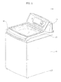
- FIG. 1 illustrates a perspective view of a laundry treatment machine 100 according to a first exemplary embodiment of the present invention
- FIG. 2 illustrates a side cross-sectional view of the laundry treatment machine 100
- FIG. 3 illustrates detailed side-cross sectional views of a lead assembly 30 and a top cover 20 shown in FIG. 2 .
- the laundry treatment machine 100 may include a cabinet 10, the top cover 20, which is placed on an upper end of the cabinet 10 and has a laundry entrance through which laundry can be put into or taken out of the laundry treatment machine 100, the lead assembly 30, which is disposed at the front of the top of the top cover 20 so as to be rotatable and to open or shut the laundry inlet/outlet hole, and a control panel 40, which is disposed at the rear of the top of the top cover 20 and provides an interface for manipulating the laundry treatment machine 100.
- the laundry treatment machine 100 may also include an outer tub 12, which is disposed in the cabinet 10 and is suspended on a supporting element 11, and an inner tub 13, which is disposed in the outer tub 12 so as to be rotatable.
- the laundry treatment machine 100 may also include a damper 14, which is disposed below the supporting element 11 and can reduce the fluctuation of the outer tub 12 when vibration is generated upon the rotation of the inner tub 13, and a pulsator 15, which is disposed at the bottom of the inner tub 13 and generates a rotating water current in the inner tub 13.
- a damper 14 which is disposed below the supporting element 11 and can reduce the fluctuation of the outer tub 12 when vibration is generated upon the rotation of the inner tub 13, and a pulsator 15, which is disposed at the bottom of the inner tub 13 and generates a rotating water current in the inner tub 13.
- the laundry treatment machine 100 may also include a motor 16, which is disposed below the outer tub 12 and rotates the inner tub 13 and the pulsator 15.
- the motor 16 may be connected to the inner tub 13 via a rotation axial member 17 and may thus be able to rotate the inner tub 13.
- a clutch (not shown) may be disposed between the inner tub 13 and the pulsator 15. The clutch may selectively transmit the rotation force of the motor 16 to the inner tub 13 and the pulsator 15. Thus, only one of the inner tub 13 and the pulsator 15 may be rotated at a time by the motor 16, or the inner tub 13 and the pulsator 15 may both be rotated at the same time by the motor 16.
- a detergent box 21, a water supply hose (not shown), and a water supply valve may be disposed in the top cover 20.
- the detergent box 21 may be installed so as to be able to be moved in and out of the top cover 20.
- the water supply hose may be connected to an external water source, and may thus be used to supply wash water into the detergent box 21.
- the water supply valve may control the supply of wash water through the water supply hose. When the water supply valve is opened, wash water from the external water source can be supplied into the detergent box 21 and then into the inner tub 13.
- the wash water supplied into the inner tub 13 through the detergent box 21 may be contained in the outer tub 12, passing through a plurality of water holes formed in the inner tub 13. and laundry may be contained in the inner tub 13.
- a drain hose 23 and a drain valve 24 may be disposed below the outer tub 12.
- the drain hose 23 may be used to discharge wash water from the outer tub 12.
- the drain valve 24 may be used to control the discharge of wash water through the drain hose 23.
- a lock device 110 may be housed in the top cover 20.
- the lock device 110 may lock or unlock the lead assembly 30 when coupling the lead assembly 30 to the top cover 20.
- the lock device 110 may include a lock element (not shown) and may thus be able to lock or unlock the top cover 20 and the lead assembly 30 by moving the lock element.
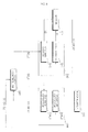
- FIG. 4 illustrates a block diagram of the laundry treatment machine 100.
- the laundry treatment machine 100 may include a display unit 210, an input unit 220, a device driving unit 240, a memory 250, a sensing unit 270, a driving unit 280, an audio output unit 290, and a control unit 230, which controls the general operation of the laundry treatment machine 100.
- the input unit 220 may include at least one input tool for inputting signals or data to the laundry treatment machine in response to user manipulation thereof. More specifically, the input unit 220 may include a manipulator 221 and a selector 222.
- the manipulator 221 may receive various data such as wash courses or wash settings and may transmit the received data to the control unit 230 during the course of the operation of the laundry treatment machine 100.
- the input unit 220 may include, but is not restricted to buttons, a dome switch, a resistive or capacitive touch pad, a jog wheel, a jog switch, a finger mouse, a rotary switch, and/or a jog dial. That is, nearly all types of device that can generate predetermined input data by being appropriately manipulated (for example, by being pushed, rotated, pressed or touched) may be used as the input unit 220.
- the sensing unit 270 may include at least one sensing tool for sensing temperature, pressure, a voltage, a current, a water level and the number of revolutions, and may transmit data obtained by the sensing to the control unit 230.
- the sensing unit 270 may measure the water level in the laundry treatment machine 100 during a water supply or drain operation, and may measure the temperature of water supplied into the laundry treatment machine 100 or the number of revolutions of a washing tub or a drum of the laundry treatment machine 100.
- the driving unit 280 may control the laundry treatment machine 100 to perform a predefined operation in response to a control command applied thereto by the control unit 230. Therefore, the laundry treatment machine 100 can perform a series of processes such as washing, rinsing and spin-drying and can thus remove dirt from laundry.
- the driving unit 280 may drive the motor 16 to rotate a washing tub or drum of the laundry treatment machine 100 and may control the operation of the motor 16 so as for the laundry treatment machine 100 to effectively remove dirt from laundry.
- the driving unit 280 may control various valves in the laundry treatment machine 100 in response to a control command applied thereto by the control unit 230 so as for the laundry treatment machine 100 to effectively perform water supply and drain operations.
- Examples of the memory 250 include, but are not restricted to a read-only memory and an electrically erasable programmable ROM (EEPROM) for storing control data regarding the laundry treatment machine 100, and a data storage means for storing data obtained by processing various operations performed by the laundry treatment machine 100.
- the storage unit 260 may be a buffer of the control unit 230, and may be used to store data temporarily. Examples of the storage unit 260 include, but are not restricted to a dynamic random access memory (DRAM) and a static random access memory (SRAM). The storage unit 260 may be incorporated into the control unit 230 or the memory 250.
- DRAM dynamic random access memory
- SRAM static random access memory
- the memory 250 may store operation information such as operating state data generated during a predetermined operation of the laundry treatment machine 100 and settings data input to the laundry treatment machine 100 via the manipulator 221 for driving the laundry treatment machine 100 to perform a predetermined operation; usage information such as the number of times the laundry treatment machine 100 has performed a predetermined operation and product specifications information of the laundry treatment machine 100; and failure information such as the cause and location of failure.
- operation information such as operating state data generated during a predetermined operation of the laundry treatment machine 100 and settings data input to the laundry treatment machine 100 via the manipulator 221 for driving the laundry treatment machine 100 to perform a predetermined operation
- usage information such as the number of times the laundry treatment machine 100 has performed a predetermined operation and product specifications information of the laundry treatment machine 100
- failure information such as the cause and location of failure.
- the memory 250 may store product information of the laundry treatment machine 100. including the operation information, the usage information and the failure information.
- the storage unit 260 may store temporary data corresponding to the operation information and the failure information.
- the product information may include the number of times the laundry treatment machine 100 has been used, wash courses provided by the laundry treatment machine 100, option settings information, error code, sensor measurements, calculation data provided by the control unit 230, and operation information regarding each part of the laundry treatment machine 100.
- the operation information may include various information necessary for driving the laundry treatment machine 100 such as wash operation information, spin-dry operation information and rinse operation information.
- the failure information may include operation failure information regarding failure that may occur during the operation of the laundry treatment machine 100, defect information, error code, information provided by the control unit 230, measurement data provided by the sensing unit 270, measurement data obtained from the motor 16. failure information of a wash water supply device, and failure information of a drain device.
- the usage information may include the number of times the laundry treatment machine 100 has been used, wash courses selected by a user, and option settings information regarding options set in the laundry treatment machine 100. That is, the usage information may include various data input to the laundry treatment machine 100 by a user and initial settings information of the laundry treatment machine 100.
- the device driving unit 240 may operate in response to a control command applied thereto by the control unit 230.
- the device driving unit 240 may rotate a motor included in the lock device 110 in consideration of whether the lead assembly 30 and the top cover 20 are placed in contact with each other, and may thus move a lock element (not shown) so as to lock or unlock the lead assembly 30 and the top cover 20.
- the control unit 230 may control the general operation of the laundry treatment machine 100.
- the control unit 230 may perform a wash operation (including washing, rinsing, and spin-drying) according to a wash mode set via the input unit 220 and a wash command issued by a user.
- the control unit 230 may determine the duration, speed and mode of driving of a driving device (not shown) based on various measurement data provided by the sensing unit 270 such as the level and temperature of water contained in a washing tub 122 or a drum (not shown) and the amount of laundry.
- control unit 230 may appropriately control a wash operation set by a user with reference to sensing results provided by the sensing unit 270.
- control unit 230 may control various valves provided in the laundry treatment machine 100 so as for the laundry treatment machine 100 to properly perform water supply and drain operations according to the progress in a whole wash process.
- the display unit 210 may display various information input to the laundry treatment machine 100 via the selector 222 and the manipulator 221, operating state information of the laundry treatment machine 100, and status information of the laundry treatment machine 100 (such as information indicating whether the laundry treatment machine 100 has completed a predetermined operation) in response to a control signal applied thereto by the control unit 230. If the laundry treatment machine 100 malfunctions, the display unit 210 may display failure information indicating the malfunction of the laundry treatment machine 100.
- Examples of the display unit 210 include a light-emitting diode (LED) display, a liquid crystal display (LCD) an organic electroluminescent display (OLED) and any other display that can visualize information by emitting light.
- LED light-emitting diode
- LCD liquid crystal display
- OLED organic electroluminescent display
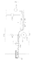
- FIG. 5 illustrates a cross-sectional view of the lock device 110.
- the lock device 110 may include a lock element 112, a motor 114, a lead 116, a common contact U, an initial contact SW1 and a lock contact SW2.
- the lock element 112 may be moved by the rotation of the motor 114.
- the lock element 114 may be moved to a first direction Q1, and may thus lock the top cover 20 and the lead assembly 30.
- the lock element 114 may be moved to a second direction Q2, and may thus unlock the top cover 20 and the lead assembly 30.
- the motor 114 may be controlled by the device driving unit 240. When a first driving voltage is supplied, the motor 114 may rotate in the first rotation direction Q1_1. When a second driving voltage is supplied, the motor 114 may rotate in the second rotation direction Q2_1.
- the lead 116 may be connected to the lead element 112.
- An upper portion 116_1 of the lead 116 may be placed in contact with the common contact U, and a lower portion 116_2 of the lead 116 may be placed in contact with at least one of the initial contact SW1 and the lock contact SW2 according to the position of the lock element 112.
- Lead bars 117_1 and 117_2 may be provided at the ends of the upper and lower portions 116_1 and 116_2, respectively, of the lead 116.
- the lead 116 6 may also be moved in the first or second direction Q1 and Q2 along the lead bars 117_1 and 117_2.
- the lead 116 may be electrically connected to at least one of the common contact U, the initial contact SW1 and the lock contact SW2, and may thus transmit an initial sensing signal or another sensing signal to the device driving unit 240 in order to indicate whether the top cover 20 and the lead assembly 30 are locked or unlocked.
- FIG. 6 illustrates a block diagram of the device driving unit 240
- FIG. 7 illustrates a circuit diagram of a first embodiment of the device driving unit 240
- the device driving unit 240 may include a motor driver 242, which rotates the motor 114 in the first or second rotation direction Q1_1 and Q2_1, a detector 244, which detects first and second driving voltages V1 and V2 supplied to the motor 114 and the position of the lock element 112, and a device controller 246, which determines whether the motor 114 is broken and whether the lead assembly 30 and the top cover are locked or unlocked based on the position of the lock element 112 and at least one of the first and second driving voltages V1 and V2 detected by the detector 244 and thus controls the motor driver 242 based on the results of the determination.
- the motor driver 242 may include first and second switches SH1 and SH2, which are switched on or off under the control of the device controller 246 so as to supply the first and second driving voltages V1 and V2 to the motor 114.
- the first and second switches SH1 and SH2 may be alternately switched on or off by the device controller 246.
- the first switch SH1 may be connected between a first power source VCC _1, which supplies the first driving voltage V1, and the motor 114.
- the second switch SH2 may be connected between a second power source VCC_2, which supplies the second driving voltage V2, and the motor 114.
- the first and second power sources VCC_1 and VCC_2 are illustrated as being separate elements, but the present invention is not restricted to this. That is, the first and second power sources VCC_1 and VCC_2 may be incorporated into a single power source with opposite polarities.
- the first and second switches SH1 and SH2 may be switched on or off in response to first and second control signals SC_1 and SC_2 generated by the device controller 246.
- the first switch SH1 may be switched on in response to the first control signal SC_1.
- the second control signal SC_2 may be applied, and thus, the second switch SH2 may be switched off in response to the second control signal SC_2.
- the detector 244 may include a voltage detector 244_1, which detects one of the first and second driving voltages V1 and V2 that are supplied to the motor 114 by the device controller 246, and a position detector 244_2, which detects the position of the lead 116 that moves along with the lock element 114 during the movement of the lock element 114 in the first or second direction Q1 or Q2.
- the voltage detector 244_1 may include a shunt resistor SR which detects one of the first and second driving voltages V1 and V2.
- the shunt resistor SR may be connected to one side of the motor 114, may detect one of the first and second driving voltages V1 and V2, and may supply the detected driving voltage to the device controller 246.
- the position detector 244_2 may detect the position of the lead 116, which moves along with the lock element 112 when the lock element 112 moves in the first or second direction Q1 and Q2.
- the position detector 244_2 may transmit an initial detection signal S1 to the device controller 246.
- the lead 116 may also be moved in the first direction Q1 and may thus lock the lead assembly 30 and the top cover 20.
- the lock element 112 may be referred to as being located at a lock position.
- the lock element 112 is located at the lock position, the common contact U and the lock contact SW2 may be electrically connected by the lead 116, and the position detector 244_2 may transmit a detection signal S2 to the device controller 246.
- the lead 116 may be moved from its initial position to a position where the lower portion of the lead 116 can contact the lock contact SW2.
- the device controller 246 may determine whether the motor 114 is broken based on the driving voltage detected by the voltage detector 244_1, and may determine whether the lead assembly 30 and the top cover 20 are locked or unlocked and whether laundry is stuck between the lead assembly 30 and the top cover 20 based on the initial detection signal S1 and the detection signal S2 provided by the position detector 244_2.
- the device controller 246 may compare the driving voltage detected by the voltage detector 244_1 with a reference voltage. Then, if the driving voltage detected by the voltage detector 244_1 is higher than or the same as the reference voltage, the device controller 246 may determine that the motor 114 operates normally. On the other hand, if the driving voltage detected by the voltage detector 244_1 is lower than the reference voltage, the device controller 246 may determine that the motor 114 is broken.
- the device controller 180 may control both the first and second switches SH1 and SH2 of the device driver 242 to be switched off.
- the device controller 246 may determine whether the lead assembly 30 and the top cover 20 are locked or unlocked based on the initial sensing signal and the detection signal S2.
- the device controller 246 may control the first and second switches SH1 and SH2 to be switched off so as to stop the motor 114 from rotating.
- the device controller 246 may apply the first and second control signals SC_1 and SC_2 to the motor 114 so as to rotate the motor 114 in the first or second rotation Q1_1 or Q2_1, and may switch on the first and second switches SH1 and SH2 so as to form first and second paths I_1 and I_2.
- the device controller 246 may serve the same functions as the control unit 230 shown in FIG. 4 .
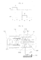
- FIG. 8 illustrates a current path diagram for explaining a first path I_1 that may be formed when the motor 114 shown in FIG. 6 rotates in the first rotation direction Q1_1
- FIG. 9 illustrates a current path diagram for explaining the second path I_2 that may be formed when the motor 114 shown in FIG. 6 rotates in the second rotation direction Q2_1.
- the device controller 246 may rotate the motor 114 in the first rotation direction Q1_1 and may thus form the first path I_1 so as to move the lock element 112 in the first direction Q1.
- the first path I_1 may be formed by applying the first control signal SC_1 to the first switch SH1 so as to switch on the first switch SH1 and supplying the first driving voltage V1 provided by the first power source VCC_1 to the motor 114.
- the second switch SH2 may be switched off in response to the second control signal SC_2, and thus, the second path I_2 may not be formed.
- the lock element 112 may be moved in the first direction Q1 and may thus lock the lead assembly 30 and the top cover 20.
- the device controller 246 may apply the first and second control signals SC_1 and SC_2 according to whether the lead assembly 30 and the top cover 20 are placed in contact with each other.
- the device controller 246 may determine whether the lead assembly 30 and the top cover 20 contact each other based on whether magnets respectively attached to the lead assembly 30 and the top cover 20 contact each other.
- the device controller 246 may rotate the motor 114 in the second rotation direction Q2_1 and may thus form the second path 1_2 so as to move the lock element 112 in the second direction Q2.
- the second path I_2 may be formed by applying the second control signal SC_2 to the second switch SH2 so as to switch on the first switch SH1 and supplying the second driving voltage V2 provided by the second power source VCC_2 to the motor 114.
- the first switch SH1 may be switched off in response to the first control signal SC_1, and thus, the first path I_1 may not be formed.
- the lock element 112 may be moved in the second direction Q2 and may thus unlock the lead assembly 30 and the top cover 20.
- the device controller 246 may receive one of the first and second driving voltages V1 and V2 detected by the voltage detector 244_1. Thereafter, if the received driving voltage is higher than or the same as the reference voltage, the device controller 246 may determine that the motor 114 operates normally. On the other hand, if the received driving voltage is lower than the reference voltage, the device controller 246 may determine that the motor 114 malfunctions.
- the device controller 246 may alert a user to the operating state of the motor 114 by using the display unit 210 or the audio output unit 280 shown in FIG. 4 .
- FIG. 10 illustrates a circuit diagram of a second embodiment of the device driving unit 240 shown in FIG. 6
- FIG. 11 illustrates a current path diagram for explaining a first path I_1 that may be formed when a motor 114 shown in FIG. 10 rotates in the first rotation direction Q1_1
- FIG. 12 illustrates a current path diagram for explaining a second path I_2 that may be formed when the motor 114 shown in FIG. 10 rotates in the second rotation direction Q2 _1.
- FIGS. 10 through 12 is similar to the exemplary embodiment of FIGS. 6 through 9 , and thus will hereinafter be described, focusing mainly on differences with the exemplary embodiment of FIGS. 6 through 9 .
- the device driving unit 240 may supply the first and second driving voltages V1 and V2 to or detect the first and second driving voltages V1 and V2 from the motor 114.
- the device driving unit 240 may include a motor driver 242, which rotates the motor 114 in the first or second rotation Q1_1 or Q2_1, a voltage detector 244_1, which detects one of the first and second driving voltages V1 and V2 that are supplied to the motor 114, and a device controller 246, which determines whether the motor 114 is broken based on the driving voltage detected by the voltage detector 244_1 and controls the motor driver 242 based on the results of the determination.
- the motor driver 242 and the voltage detector 244_1 are the same as their respective counterparts of FIGS. 6 and 7 , and thus, detailed descriptions thereof will be omitted.
- the device driving unit 240 may also include a comparer 246_1, which is connected between a shunt resistor SR of the voltage detector 244_1 and the device controller 246 and compares the driving voltage detected by the voltage detector 244_1 with a reference voltage.
- the comparer 246_1 may output a first comparison signal B1 to the device controller 246.
- the comparer 246_1 may output a second comparison signal B2 to the device controller 246.
- the comparer 246_1 may be an operational amplifier and may be used as a voltage flower.
- the device controller 246 may apply first and second control signals SC_1 and SC_2 to the motor 114 so as to rotate the motor 114 in the first or second rotation direction Q1_1 or Q2_1, and may switch on the first and second switches SH1 and SH2 so as to form first and second paths I_1 and I_2.
- the device controller 246 may control the motor driver 242 to rotate the motor 114 in the first or second rotation direction Q1_1 or Q2_1 in response to the first or second comparison signal B1 or B2 provided by the comparer 246_1.
- the device controller 246 may rotate the motor 114 in the first rotation direction Q1_1 and may thus form the first path 1_1 so as to move the lock element 112 in the first direction Q1.
- the first path 1_1 may be formed by applying the first control signal SC_1 to the first switch SH1 so as to switch on the first switch SH1 and supplying the first driving voltage V1 provided by the first power source VCC_1 to the motor 114.
- the second switch SH2 may be switched off in response to the second control signal SC_2, and thus, the second path I_2 may not be formed.
- the lock element 112 may be moved in the first direction Q1 and may thus lock the lead assembly 30 and the top cover 20.
- the comparer 246_1 may compare the first driving voltage V1 detected by the voltages detector 244_1 with the reference voltage and may transmit one of the first and second comparison signals B1 and B2 to the device controller 246 based on the results of the comparison.
- the device controller 246 may determine whether the motor 114 operates normally or malfunctions based on the comparison signal provided by the comparer 246_1.
- the device controller 246 may apply the first and second control signals SC_1 and SC_2 according to whether the lead assembly 30 and the top cover 20 are placed in contact with each other.
- the device controller 246 may determine whether the lead assembly 30 and the top cover 20 contact each other based on whether the magnets of the lead assembly 30 and the top cover 20 contact each other.
- the device controller 246 may rotate the motor 114 in the second rotation direction Q2_1 and may thus form the second path I_2 so as to move the lock element 112 in the second direction Q2.
- the second path I_2 may be formed by applying the second control signal SC_2 to the second switch SH2 so as to switch on the first switch SH1 and supplying the second driving voltage V2 provided by the second power source VCC_2 to the motor 114.
- the first switch SH1 may be switched off in response to the first control signal SC_1, and thus, the first path I_1 may not be formed.
- the lock element 112 may be moved in the second direction Q2 and may thus unlock the lead assembly 30 and the top cover 20.
- the comparer 246_1 may compare the second driving voltage V2 detected by the voltage detector 244_1 with the reference voltage and may transmit one of the first and second comparison signals B1 and B2 to the device controller 246 based on the results of the comparison.
- the device controller 246 may determine whether the motor 114 operates normally or malfunctions based on the comparison signal provided by the compare 246_1.
- the device controller 246 may receive one of the first and second driving voltages V1 and V2 detected by the voltage detector 244_1. Thereafter, if the received driving voltage is higher than or the same as the reference voltage, the device controller 246 may determine that the motor 114 operates normally. On the other hand, if the received driving voltage is lower than the reference voltage, the device controller 246 may determine that the motor 114 malfunctions.
- the device controller 246 may alert a user to the operating state of the motor 114 by using the display unit 210 or the audio output unit 280 shown in FIG. 4 .
- FIG. 13 illustrates a signal waveform diagram of signals for detecting the position of the lock element 112
- FIG. 14 illustrates a schematic diagram for explaining the operations of the lock device 110 and the device driving unit 240 during a first time period T1 shown in FIG. 13
- FIG. 15 illustrates a schematic diagram for explaining the operations of the lock device 110 and the device driving unit 240 during a second time period T2 shown in FIG. 13
- FIG. 16 illustrates a schematic diagram for explaining the operations of the lock device 110 and the device driving unit 240 during a third time period T3 shown in FIG. 13
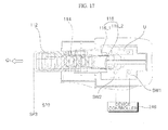
- FIG. 17 illustrates a schematic diagram for explaining the operations of the lock device 110 and the device driving unit 240 during a fourth time period T4 shown in FIG. 13 .
- FIG. 13 illustrates the waveforms of the initial detection signal S1 and the detection signal S2.
- the initial detection signal S1 may be output when the common contact U and the initial contact SW1 are electrically connected by the lead 116
- the detection signal S2 may be output when the common contact U and the lock contact SW2 are electrically connected by the lead 116.
- the lock element 112 may be maintained at an unlock position SP1, and the initial detection signal S1 may be output.
- the lock element 112 may be moved from the unlock position SP1 to a lock position SP2, and none of the initial detection signal S1 and the detection signal S2 may be output.
- the lock element 112 may be maintained at the lock position SP2, and the detection signal S2 may be output.
- the lock element 112 may be moved from the lock position SP2 to a maximum position SP3, and none of the initial detection signal S1 and the detection signal S2 may be output.
- FIG. 14 illustrates the position of the lock element 112 during the first time period T1.
- the lock element 112 may be located at its initial position, i.e., the unlock position SP1, and the lead 116, which moves along with the lock element 112, may be located at a position where it can electrically connect the common contact U and the initial contact SW1.
- the device controller 246 of the device driving unit 240 may control the motor driver 242 not to rotate the motor 114 since the lead assembly 30 and the top cover 20 are yet to be coupled, and may receive the initial detection signal S1 from the position detector 244_2.
- FIG. 15 illustrates the position of the lock element 112 during the second time period T2.
- the lock element 112 may be located between the unlock position SP1 and the lock position SP2.
- the device controller 246 may determine whether the lead assembly 30 and the top cover 20 are coupled based on whether the magnets of the lead assembly 30 and the top cover 20 are placed in contact with each other. If the lead assembly 30 and the top cover 20 are determined to be coupled, the device controller 246 may transmit the first control signal SC_1 to the motor driver 242.
- the motor driver 242 may rotate the motor 114 in the first rotation direction Q1_1 in response to the first control signal SC_1 and may thus move the lock element 112 in the first direction Q1.
- the device controller 246 may not be provided with the initial detection signal S1 and the detection signal S2 by the position detector 244_2.
- the device controller 246 may stop the rotation of the motor 114, and may determine that laundry is stuck between the lead assembly 30 and the top cover 20. Therefore, the device controller 246 may generate lock error information and may thus output the lock error information to a user.
- the device controller 246 may control the motor driver 242 to stop rotating the motor 114.
- FIG. 16 illustrates the position of the lock element 112 during the third time period T3.
- the lock element 112 may be located at the lock position SP2.
- the device controller 246 may receive the detection signal S2 from the position detector 244_2 because the upper and lower portions 116_1 and 116_2 of the lead 116 are placed in contact with the common contact U and the lock contact SW2, respectively.
- the device controller 246 may determine that the lead assembly 30 and the top cover 20 are locked by the lock element 112.
- FIG. 17 illustrates the position of the lock element 112 during the fourth time period T4.
- the lock element 112 may be moved past the lock position SP2 and may thus reach the maximum position SP3.
- the device controller 246 may determine that the lock element 112 is located at the maximum position SP3, and that the lead assembly 30 and the top cover 20 are detached from each other. Therefore, the device controller 246 may generate detachment information indicating that the lead assembly 30 and the top cover 20 are no longer coupled, and may output the detachment information to a user.
- the detachment information may also indicate whether laundry is stuck between the lead assembly 30 and the top cover 20 and whether the lead assembly 30 and the top cover 20 are opened.
- the upper portion 116_1 of the lead 116 contacts the common contact U, but the lower portion 116_2 of the lead 116 does not contact any one of the initial contact SW1 and the lock contact SW2.
- the device controller 246 may control the motor driver 242 to rotate the motor 114 in the second rotation direction Q2_1 and may thus move the lock element 112 in the second direction Q2.
- FIG. 18 illustrates a flowchart of a control method of a laundry treatment machine, according to a first exemplary embodiment of the present invention, and particularly, how to determine whether the motor 114 is broken.
- the motor 114 may be rotated in the first rotation direction Q1_1 in response to an input command so as to move the lock element 112 from the unlock position SP1 to the lock position SP2 (S100). More specifically, the device controller 246 may determine whether the lead assembly 30 and the top cover 20 are coupled.
- the device controller 246 may transmit the first control signal SC_1 to the motor driver 242 and may thus control the motor driver 242 to rotate the motor 114 in the first rotation direction Q1_1 in order to move the lock element 112 from the unlock position SP1 to the lock position SP2.
- a driving voltage supplied to the motor 114 may be detected (S102). Thereafter, the detected driving voltage may be compare with a reference voltage, and it may be determined whether the motor 114 is broken based on the results of the comparison (S104). More specifically, when the motor 114 rotates in the first rotation direction Q1_1, the voltage detector 244_1 may detect the first driving voltage V1 from the motor 114. Then, the device controller 246 may compare the first driving voltage V1 with the reference voltage. Thereafter, if the first driving voltage V1 is lower than the reference voltage, the device controller 246 may determine that the motor 114 is broken. On the other hand, if the first driving voltage V1 is higher than or the same as the reference voltage, the device controller 246 may determine that the motor 114 operates normally.
- failure information may be output in order to alert a user (S106).
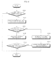
- FIG. 19 illustrates a flowchart of a control method of a laundry treatment machine, according to a second exemplary embodiment of the present invention, and particularly, how to determines whether the lead assembly 30 and the top cover 20 are locked or unlocked and whether laundry is stuck between the lead assembly 30 and the top cover 20 based on the position of the lock element 112.
- it may be determined whether the lead assembly 30 and the top cover 20 are coupled (S200). More specifically, the device controller 246 may determine whether the lead assembly 30 and the top cover 20 are coupled by determining whether the magnets of the lead assembly 30 and the top cover 20 are placed in contact with each other.
- the device controller 246 can detect voltage variations caused by variations in the magnetic fields of the magnets of the lead assembly 30 and the top cover 20.
- the lock element 112 may be moved from the unlock position SP1 to the lock position SP2 in response to an input command (S202). More specifically, the device controller 246 may control the motor driver 242 to rotate the motor 114 in the first rotation direction Q1_1 and may thus move the lock element 112 in the first direction Q1. As a result, the lock element 112 can be moved in the first direction Q1 from the unlock position SP1 to the lock position SP2.
- the device controller 246 may determine whether the lock element 112 has been moved from the unlock position SP1 to the lock position SP2.
- the position detector 244_2 may detect the positions of the upper and lower portions 116_1 and 116_2 of the lead 116, which moves along with the lock element 112. Since the distance by which the lock element 112 moves is the same as the distance by which the lead 116 moves, the position detector 244_2 can determine the position of the lock element 112 based on the position of the lead 116.
- the upper and lower portions 116_1 and 116_2 of the lead 116 may contact the common contact U and the initial contact SW1, respectively, and the position detector 244_2 may transmit the initial detection signal to the device controller 246 as the result of the detection of the position of the lock element 112.
- the upper and lower portions 116_1 and 116_2 of the lead may be placed in contact with the common contact U and the lock contact SW2, respectively, and the position detector 244_2 may transmit the detection signal S2 to the device controller 246 as the result of the detection of the position of the lock element 112.
- lock information may be generated (S206).
- lock error information may be generated (S208). More specifically, if the detection signal S2 is received from the position detector 244_2, the device controller 246 may determine that the lead assembly 30 and the top cover 20 are locked, and may thus generate and output the lock information in order to alert a user.
- the device controller 246 may determine that laundry is stuck between the lead assembly 30 and the top cover 20, and may thus generate and output the lock error information in order to alert a user.
- the device controller 246 may determine whether the lock element 112 has been moved past the lock position SP2 and is located at the maximum position SP3.
- the lower portion 116_2 of the lead 116 may not contact the lock contact SW2 any longer, and thus, the detection signal S2 may not be detected any longer.
- the device controller 246 may determine that the lead assembly 30 and the top cover 20 are no longer coupled. and may thus generate and output detachment information in order to alert a user.
- the device controller 246 may rotate the motor 112 in the second rotation direction Q2_1 and may thus move the lock element 112 back to the unlock position SP1.
Landscapes
- Engineering & Computer Science (AREA)
- Textile Engineering (AREA)
- Power Engineering (AREA)
- Control Of Washing Machine And Dryer (AREA)
- Main Body Construction Of Washing Machines And Laundry Dryers (AREA)
Abstract

Description
- This application claims priority from Korean Patent Application No.
10-2009-0071032 10-2009-0071033 10-2009-0071034 10-2009-0071035 filed on July 31, 2009 10-2009-0104443 10-2009-0104444 filed on October 30, 2009 10-2010-0072496 filed on July 27, 2010 US Provisional Patent Application No. 61/230,588 61/230,519 61/230,624 61/230,568 filed on July 31, 2009 - The present invention relates to a laundry treatment machine and a control method thereof, and more particularly, to a laundry treatment machine, which can drive a locking element when coupling a lead assembly and a top cover and then lock or unlock the lead assembly and the top cover with the aid of the lock element so as to determine whether laundry is stuck between the lead assembly and the top cover and can easily determine whether a motor that moves the locking element is broken, and a control method of the laundry treatment machine.
- Laundry treatment machines include various types of machines that can treat laundry by causing a physical and/or chemical reaction with laundry such as a washing machine for washing laundry by using a chemical reaction between water and detergent and the friction between water and laundry, a dryer for drying wet laundry, and a refresher capable of preventing allergies from laundry and facilitating the washing of laundry by spraying heated water vapor onto laundry.
- Washing machines, which are a type of laundry treatment machine, are largely classified into an agitator-type washing machine, a drum-type washing machine and a pulsator-type washing machine. In general, washing machines wash laundry by sequentially performing a wash process, a rinse process and a spin-dry process. Washing machines may be configured to selectively perform only some of the wash process, the rinse process and the spin-dry process at users' choice and to choose an appropriate washing method for laundry.
- The present invention provides a laundry treatment machine, which can drive a locking element when coupling a lead assembly and a top cover and then lock or unlock the lead assembly and the top cover with the aid of the lock element so as to determine whether laundry is stuck between the lead assembly and the top cover and can easily determine whether a motor that moves the locking element is broken, and a control method of the laundry treatment machine.
- According to an aspect of the present invention, there is provided a laundry treatment machine including a top cover configured to have a laundry entrance hole through which laundry is put in or taken out of the laundry treatment machine; a lead assembly configured to be disposed above the top cover so as to be rotatable, the lead assembly opening or shutting the laundry entrance hole; a lock device configured to include a lock element and a lead, the lock element locking or unlocking the lead assembly and the top cover, and the lead moving in the same direction as the lock element; and a device driving unit configured to detect a position of the lead, determine an operating state of the lock device based on the detected position of the lead, and control an operation of the lock device, wherein, if the lock element is moved from its initial unlock position to a lock position where it can lock the lead assembly and the top cover, the device driving unit receives an initial detection signal, and if no detection signal is received within a first setting time of the receipt of the initial detection signal, the device driving unit determines that the lead assembly and the top cover are not properly locked, and outputs first error information.
- According to another aspect of the present invention, there is provided a laundry treatment machine including a device driving unit configured to control a lock device including a lock element, which locks or unlocks a lead assembly and a top cover, and a lead, which moves along with the lock element, when the lead assembly and the top cover are coupled, wherein the device driving unit includes a position detector, which, if the lock element is moved from its initial unlock position to a lock position where it can lock the lead assembly and the top cover, determines whether the lead is moved from its initial position to a predetermined position and outputs a first detection signal as the result of the determination, and a device controller, which determines that the lead assembly and the top cover are locked and outputs lock information if the first detection signal is received, and which determines that the lead assembly and the top cover are not locked and outputs lock error information if the first detection signal is not received.
- According to another aspect of the present invention, there is provided a control method of a laundry treatment machine, the control method including, if the lead assembly and the top cover are coupled, moving a lock element from its initial unlock position in response to an input command; detecting a position of the lock element; and generating lock information if the lock element is located at a lock position, and generating lock error information if the lock element is not located at the lock position.
- According to another aspect of the present invention, there is provided a control method of a laundry treatment machine, the control method including, if a lead assembly and a top cover are coupled, driving a motor to move a lock element from its initial unlock position to a lock position in response to an input command; detecting a driving voltage supplied to the motor; and determining whether the motor is broken based on the detected driving voltage.
- The above and other features and advantages of the present invention will become more apparent by describing in detail preferred embodiments thereof with reference to the attached drawings in which:
-
FIG. 1 illustrates a perspective view of a laundry treatment machine according to a first exemplary embodiment of the present invention; -
FIG. 2 illustrates a side cross-sectional view of the laundry treatment machine; -
FIG. 3 illustrates detailed side-cross sectional views of a lead assembly and a top cover shown inFIG. 2 ; -
FIG. 4 illustrates a block diagram of the laundry treatment machine; -
FIG. 5 illustrates a cross-sectional view of a lock device shown inFIG. 1 ; -
FIG. 6 illustrates a block diagram of a device driving unit shown inFIG. 4 : -
FIG. 7 illustrates a circuit diagram of a first embodiment of the device driving unit shown inFIG. 6 : -
FIG. 8 illustrates a current path diagram for explaining a first path formed when a motor shown inFIG. 7 rotates in a first rotation direction; -
FIG. 9 illustrates a current path diagram for explaining a second path formed when the motor shown inFIG. 7 rotates in a second rotation; -
FIG. 10 illustrates a circuit diagram of a second embodiment of the device driving unit shown inFIG. 6 ; -
FIG. 11 illustrates a current path diagram for explaining a first path formed when a motor shown inFIG. 10 rotates in a first rotation direction; -
FIG. 12 illustrates a current path diagram for explaining a second path formed when the motor shown inFIG. 10 rotates in a second rotation; -
FIG. 13 illustrates a signal waveform diagram of signals for detecting the position of a lock element shown inFIG. 6 ; -
FIG. 14 illustrates a schematic diagram for explaining the operations of the lock device and the device driving unit during a first time period shown inFIG. 13 ; -
FIG. 15 illustrates a schematic diagram for explaining the operations of the lock device and the device driving unit during a second time period shown inFIG. 13 ; -
FIG. 16 illustrates a schematic diagram for explaining the operations of the lock device and the device driving unit during a third time period shown inFIG. 13 ; - F3G. 17 illustrates a schematic diagram for explaining the operations of the lock device and the device driving unit during a fourth time period shown in
FIG. 13 ; -
FIG. 18 illustrates a flowchart of a control method of a laundry treatment machine, according to a first exemplary embodiment of the present invention; and -
FIG. 19 illustrates a flowchart of a control method of a laundry treatment machine, according to a second exemplary embodiment of the present invention. - The present invention will hereinafter be described in detail with reference to the accompanying drawings in which exemplary embodiments of the invention are shown. In the drawings, like reference numerals indicate like elements.
-
FIG. 1 illustrates a perspective view of alaundry treatment machine 100 according to a first exemplary embodiment of the present invention,FIG. 2 illustrates a side cross-sectional view of thelaundry treatment machine 100, andFIG. 3 illustrates detailed side-cross sectional views of alead assembly 30 and atop cover 20 shown inFIG. 2 . Referring toFIGS. 1 through 3 , thelaundry treatment machine 100 may include acabinet 10, thetop cover 20, which is placed on an upper end of thecabinet 10 and has a laundry entrance through which laundry can be put into or taken out of thelaundry treatment machine 100, thelead assembly 30, which is disposed at the front of the top of thetop cover 20 so as to be rotatable and to open or shut the laundry inlet/outlet hole, and acontrol panel 40, which is disposed at the rear of the top of thetop cover 20 and provides an interface for manipulating thelaundry treatment machine 100. - The
laundry treatment machine 100 may also include anouter tub 12, which is disposed in thecabinet 10 and is suspended on a supportingelement 11, and aninner tub 13, which is disposed in theouter tub 12 so as to be rotatable. - The
laundry treatment machine 100 may also include adamper 14, which is disposed below the supportingelement 11 and can reduce the fluctuation of theouter tub 12 when vibration is generated upon the rotation of theinner tub 13, and apulsator 15, which is disposed at the bottom of theinner tub 13 and generates a rotating water current in theinner tub 13. - The
laundry treatment machine 100 may also include amotor 16, which is disposed below theouter tub 12 and rotates theinner tub 13 and thepulsator 15. Themotor 16 may be connected to theinner tub 13 via a rotationaxial member 17 and may thus be able to rotate theinner tub 13. A clutch (not shown) may be disposed between theinner tub 13 and thepulsator 15. The clutch may selectively transmit the rotation force of themotor 16 to theinner tub 13 and thepulsator 15. Thus, only one of theinner tub 13 and thepulsator 15 may be rotated at a time by themotor 16, or theinner tub 13 and thepulsator 15 may both be rotated at the same time by themotor 16. - A
detergent box 21, a water supply hose (not shown), and a water supply valve may be disposed in thetop cover 20. Thedetergent box 21 may be installed so as to be able to be moved in and out of thetop cover 20. The water supply hose may be connected to an external water source, and may thus be used to supply wash water into thedetergent box 21. The water supply valve may control the supply of wash water through the water supply hose. When the water supply valve is opened, wash water from the external water source can be supplied into thedetergent box 21 and then into theinner tub 13. - The wash water supplied into the
inner tub 13 through thedetergent box 21 may be contained in theouter tub 12, passing through a plurality of water holes formed in theinner tub 13. and laundry may be contained in theinner tub 13. - A
drain hose 23 and adrain valve 24 may be disposed below theouter tub 12. Thedrain hose 23 may be used to discharge wash water from theouter tub 12. Thedrain valve 24 may be used to control the discharge of wash water through thedrain hose 23. - A
lock device 110 may be housed in thetop cover 20. Thelock device 110 may lock or unlock thelead assembly 30 when coupling thelead assembly 30 to thetop cover 20. - More specifically, the
lock device 110 may include a lock element (not shown) and may thus be able to lock or unlock thetop cover 20 and thelead assembly 30 by moving the lock element. -
FIG. 4 illustrates a block diagram of thelaundry treatment machine 100. Referring toFIG. 4 , thelaundry treatment machine 100 may include adisplay unit 210, aninput unit 220, adevice driving unit 240, amemory 250, asensing unit 270, adriving unit 280, anaudio output unit 290, and acontrol unit 230, which controls the general operation of thelaundry treatment machine 100. - The
input unit 220 may include at least one input tool for inputting signals or data to the laundry treatment machine in response to user manipulation thereof. More specifically, theinput unit 220 may include amanipulator 221 and aselector 222. - The
manipulator 221 may receive various data such as wash courses or wash settings and may transmit the received data to thecontrol unit 230 during the course of the operation of thelaundry treatment machine 100. - The
input unit 220 may include, but is not restricted to buttons, a dome switch, a resistive or capacitive touch pad, a jog wheel, a jog switch, a finger mouse, a rotary switch, and/or a jog dial. That is, nearly all types of device that can generate predetermined input data by being appropriately manipulated (for example, by being pushed, rotated, pressed or touched) may be used as theinput unit 220. - The
sensing unit 270 may include at least one sensing tool for sensing temperature, pressure, a voltage, a current, a water level and the number of revolutions, and may transmit data obtained by the sensing to thecontrol unit 230. - For example, the
sensing unit 270 may measure the water level in thelaundry treatment machine 100 during a water supply or drain operation, and may measure the temperature of water supplied into thelaundry treatment machine 100 or the number of revolutions of a washing tub or a drum of thelaundry treatment machine 100. - The driving
unit 280 may control thelaundry treatment machine 100 to perform a predefined operation in response to a control command applied thereto by thecontrol unit 230. Therefore, thelaundry treatment machine 100 can perform a series of processes such as washing, rinsing and spin-drying and can thus remove dirt from laundry. - For example, the driving
unit 280 may drive themotor 16 to rotate a washing tub or drum of thelaundry treatment machine 100 and may control the operation of themotor 16 so as for thelaundry treatment machine 100 to effectively remove dirt from laundry. In addition, the drivingunit 280 may control various valves in thelaundry treatment machine 100 in response to a control command applied thereto by thecontrol unit 230 so as for thelaundry treatment machine 100 to effectively perform water supply and drain operations. - Examples of the
memory 250 include, but are not restricted to a read-only memory and an electrically erasable programmable ROM (EEPROM) for storing control data regarding thelaundry treatment machine 100, and a data storage means for storing data obtained by processing various operations performed by thelaundry treatment machine 100. Thestorage unit 260 may be a buffer of thecontrol unit 230, and may be used to store data temporarily. Examples of thestorage unit 260 include, but are not restricted to a dynamic random access memory (DRAM) and a static random access memory (SRAM). Thestorage unit 260 may be incorporated into thecontrol unit 230 or thememory 250. - The
memory 250 may store operation information such as operating state data generated during a predetermined operation of thelaundry treatment machine 100 and settings data input to thelaundry treatment machine 100 via themanipulator 221 for driving thelaundry treatment machine 100 to perform a predetermined operation; usage information such as the number of times thelaundry treatment machine 100 has performed a predetermined operation and product specifications information of thelaundry treatment machine 100; and failure information such as the cause and location of failure. - The
memory 250 may store product information of thelaundry treatment machine 100. including the operation information, the usage information and the failure information. Thestorage unit 260 may store temporary data corresponding to the operation information and the failure information. For example, the product information may include the number of times thelaundry treatment machine 100 has been used, wash courses provided by thelaundry treatment machine 100, option settings information, error code, sensor measurements, calculation data provided by thecontrol unit 230, and operation information regarding each part of thelaundry treatment machine 100. - The operation information may include various information necessary for driving the
laundry treatment machine 100 such as wash operation information, spin-dry operation information and rinse operation information. - The failure information may include operation failure information regarding failure that may occur during the operation of the
laundry treatment machine 100, defect information, error code, information provided by thecontrol unit 230, measurement data provided by thesensing unit 270, measurement data obtained from themotor 16. failure information of a wash water supply device, and failure information of a drain device. - The usage information may include the number of times the
laundry treatment machine 100 has been used, wash courses selected by a user, and option settings information regarding options set in thelaundry treatment machine 100. That is, the usage information may include various data input to thelaundry treatment machine 100 by a user and initial settings information of thelaundry treatment machine 100. - The
device driving unit 240 may operate in response to a control command applied thereto by thecontrol unit 230. Thedevice driving unit 240 may rotate a motor included in thelock device 110 in consideration of whether thelead assembly 30 and thetop cover 20 are placed in contact with each other, and may thus move a lock element (not shown) so as to lock or unlock thelead assembly 30 and thetop cover 20. - The
control unit 230 may control the general operation of thelaundry treatment machine 100. Thecontrol unit 230 may perform a wash operation (including washing, rinsing, and spin-drying) according to a wash mode set via theinput unit 220 and a wash command issued by a user. Thecontrol unit 230 may determine the duration, speed and mode of driving of a driving device (not shown) based on various measurement data provided by thesensing unit 270 such as the level and temperature of water contained in a washing tub 122 or a drum (not shown) and the amount of laundry. - That is, the
control unit 230 may appropriately control a wash operation set by a user with reference to sensing results provided by thesensing unit 270. In addition, thecontrol unit 230 may control various valves provided in thelaundry treatment machine 100 so as for thelaundry treatment machine 100 to properly perform water supply and drain operations according to the progress in a whole wash process. - The
display unit 210 may display various information input to thelaundry treatment machine 100 via theselector 222 and themanipulator 221, operating state information of thelaundry treatment machine 100, and status information of the laundry treatment machine 100 (such as information indicating whether thelaundry treatment machine 100 has completed a predetermined operation) in response to a control signal applied thereto by thecontrol unit 230. If thelaundry treatment machine 100 malfunctions, thedisplay unit 210 may display failure information indicating the malfunction of thelaundry treatment machine 100. - Examples of the
display unit 210 include a light-emitting diode (LED) display, a liquid crystal display (LCD) an organic electroluminescent display (OLED) and any other display that can visualize information by emitting light. -
FIG. 5 illustrates a cross-sectional view of thelock device 110. Referring toFIG. 5 , thelock device 110 may include alock element 112, amotor 114, alead 116, a common contact U, an initial contact SW1 and a lock contact SW2. - The
lock element 112 may be moved by the rotation of themotor 114. - More specifically, when the
motor 114 rotates in a first rotation direction Q1_1, thelock element 114 may be moved to a first direction Q1, and may thus lock thetop cover 20 and thelead assembly 30. On the other hand, when themotor 114 rotates in a second rotation direction Q2 _1, thelock element 114 may be moved to a second direction Q2, and may thus unlock thetop cover 20 and thelead assembly 30. - The
motor 114 may be controlled by thedevice driving unit 240. When a first driving voltage is supplied, themotor 114 may rotate in the first rotation direction Q1_1. When a second driving voltage is supplied, themotor 114 may rotate in the second rotation direction Q2_1. - The
lead 116 may be connected to thelead element 112. An upper portion 116_1 of thelead 116 may be placed in contact with the common contact U, and a lower portion 116_2 of thelead 116 may be placed in contact with at least one of the initial contact SW1 and the lock contact SW2 according to the position of thelock element 112. Lead bars 117_1 and 117_2 may be provided at the ends of the upper and lower portions 116_1 and 116_2, respectively, of thelead 116. When thelock element 112 is moved, thelead 116 6 may also be moved in the first or second direction Q1 and Q2 along the lead bars 117_1 and 117_2. - The
lead 116 may be electrically connected to at least one of the common contact U, the initial contact SW1 and the lock contact SW2, and may thus transmit an initial sensing signal or another sensing signal to thedevice driving unit 240 in order to indicate whether thetop cover 20 and thelead assembly 30 are locked or unlocked. -
FIG. 6 illustrates a block diagram of thedevice driving unit 240, andFIG. 7 illustrates a circuit diagram of a first embodiment of thedevice driving unit 240. Referring toFIGS. 6 and7 , thedevice driving unit 240 may include amotor driver 242, which rotates themotor 114 in the first or second rotation direction Q1_1 and Q2_1, adetector 244, which detects first and second driving voltages V1 and V2 supplied to themotor 114 and the position of thelock element 112, and adevice controller 246, which determines whether themotor 114 is broken and whether thelead assembly 30 and the top cover are locked or unlocked based on the position of thelock element 112 and at least one of the first and second driving voltages V1 and V2 detected by thedetector 244 and thus controls themotor driver 242 based on the results of the determination. - The
motor driver 242 may include first and second switches SH1 and SH2, which are switched on or off under the control of thedevice controller 246 so as to supply the first and second driving voltages V1 and V2 to themotor 114. - The first and second switches SH1 and SH2 may be alternately switched on or off by the
device controller 246. The first switch SH1 may be connected between a first power source VCC _1, which supplies the first driving voltage V1, and themotor 114. The second switch SH2 may be connected between a second power source VCC_2, which supplies the second driving voltage V2, and themotor 114. - The first and second power sources VCC_1 and VCC_2 are illustrated as being separate elements, but the present invention is not restricted to this. That is, the first and second power sources VCC_1 and VCC_2 may be incorporated into a single power source with opposite polarities.
- The first and second switches SH1 and SH2 may be switched on or off in response to first and second control signals SC_1 and SC_2 generated by the
device controller 246. - For example, if the first control signal SC_1 is applied, the first switch SH1 may be switched on in response to the first control signal SC_1. Then, the second control signal SC_2 may be applied, and thus, the second switch SH2 may be switched off in response to the second control signal SC_2.
- The
detector 244 may include a voltage detector 244_1, which detects one of the first and second driving voltages V1 and V2 that are supplied to themotor 114 by thedevice controller 246, and a position detector 244_2, which detects the position of thelead 116 that moves along with thelock element 114 during the movement of thelock element 114 in the first or second direction Q1 or Q2. - The voltage detector 244_1 may include a shunt resistor SR which detects one of the first and second driving voltages V1 and V2.
- The shunt resistor SR may be connected to one side of the
motor 114, may detect one of the first and second driving voltages V1 and V2, and may supply the detected driving voltage to thedevice controller 246. - The position detector 244_2 may detect the position of the
lead 116, which moves along with thelock element 112 when thelock element 112 moves in the first or second direction Q1 and Q2. - When the
lock element 112 is located at its initial position, the common contact U and the initial contact SW1 are electrically connected by thelead 116. In this case, the position detector 244_2 may transmit an initial detection signal S1 to thedevice controller 246. - Then, if the
motor 114 rotates in the first rotation direction Q1_1 and thus thelock element 112 is moved in the first direction Q1 by themotor 114, thelead 116 may also be moved in the first direction Q1 and may thus lock thelead assembly 30 and thetop cover 20. In this case, thelock element 112 may be referred to as being located at a lock position. When thelock element 112 is located at the lock position, the common contact U and the lock contact SW2 may be electrically connected by thelead 116, and the position detector 244_2 may transmit a detection signal S2 to thedevice controller 246. - That is, if the
lock element 112 is moved to a lock position where it can lock thelead assembly 30 and thetop cover 20, thelead 116 may be moved from its initial position to a position where the lower portion of thelead 116 can contact the lock contact SW2. - The
device controller 246 may determine whether themotor 114 is broken based on the driving voltage detected by the voltage detector 244_1, and may determine whether thelead assembly 30 and thetop cover 20 are locked or unlocked and whether laundry is stuck between thelead assembly 30 and thetop cover 20 based on the initial detection signal S1 and the detection signal S2 provided by the position detector 244_2. - The
device controller 246 may compare the driving voltage detected by the voltage detector 244_1 with a reference voltage. Then, if the driving voltage detected by the voltage detector 244_1 is higher than or the same as the reference voltage, thedevice controller 246 may determine that themotor 114 operates normally. On the other hand, if the driving voltage detected by the voltage detector 244_1 is lower than the reference voltage, thedevice controller 246 may determine that themotor 114 is broken. - If the
motor 114 is determined to be broken, the device controller 180 may control both the first and second switches SH1 and SH2 of thedevice driver 242 to be switched off. - The
device controller 246 may determine whether thelead assembly 30 and thetop cover 20 are locked or unlocked based on the initial sensing signal and the detection signal S2. - If the detection signal S2 is not received even when the
motor 114 operates normally or if the initial detection signal S1 is received, thedevice controller 246 may control the first and second switches SH1 and SH2 to be switched off so as to stop themotor 114 from rotating. - The
device controller 246 may apply the first and second control signals SC_1 and SC_2 to themotor 114 so as to rotate themotor 114 in the first or second rotation Q1_1 or Q2_1, and may switch on the first and second switches SH1 and SH2 so as to form first and second paths I_1 and I_2. - In this exemplary embodiment, the
device controller 246 may serve the same functions as thecontrol unit 230 shown inFIG. 4 . -
FIG. 8 illustrates a current path diagram for explaining a first path I_1 that may be formed when themotor 114 shown inFIG. 6 rotates in the first rotation direction Q1_1, andFIG. 9 illustrates a current path diagram for explaining the second path I_2 that may be formed when themotor 114 shown inFIG. 6 rotates in the second rotation direction Q2_1. Referring toFIGS. 8 and9 , thedevice controller 246 may rotate themotor 114 in the first rotation direction Q1_1 and may thus form the first path I_1 so as to move thelock element 112 in the first direction Q1. - That is, the first path I_1 may be formed by applying the first control signal SC_1 to the first switch SH1 so as to switch on the first switch SH1 and supplying the first driving voltage V1 provided by the first power source VCC_1 to the
motor 114. - In this case, the second switch SH2 may be switched off in response to the second control signal SC_2, and thus, the second path I_2 may not be formed.
- When the first path I_1 is formed, the
lock element 112 may be moved in the first direction Q1 and may thus lock thelead assembly 30 and thetop cover 20. - The
device controller 246 may apply the first and second control signals SC_1 and SC_2 according to whether thelead assembly 30 and thetop cover 20 are placed in contact with each other. Thedevice controller 246 may determine whether thelead assembly 30 and thetop cover 20 contact each other based on whether magnets respectively attached to thelead assembly 30 and thetop cover 20 contact each other. - The
device controller 246 may rotate themotor 114 in the second rotation direction Q2_1 and may thus form the second path 1_2 so as to move thelock element 112 in the second direction Q2. - That is, the second path I_2 may be formed by applying the second control signal SC_2 to the second switch SH2 so as to switch on the first switch SH1 and supplying the second driving voltage V2 provided by the second power source VCC_2 to the
motor 114. - In this case, the first switch SH1 may be switched off in response to the first control signal SC_1, and thus, the first path I_1 may not be formed.
- When the second path I_2 is formed, the
lock element 112 may be moved in the second direction Q2 and may thus unlock thelead assembly 30 and thetop cover 20. - The
device controller 246 may receive one of the first and second driving voltages V1 and V2 detected by the voltage detector 244_1. Thereafter, if the received driving voltage is higher than or the same as the reference voltage, thedevice controller 246 may determine that themotor 114 operates normally. On the other hand, if the received driving voltage is lower than the reference voltage, thedevice controller 246 may determine that themotor 114 malfunctions. - The
device controller 246 may alert a user to the operating state of themotor 114 by using thedisplay unit 210 or theaudio output unit 280 shown inFIG. 4 . -
FIG. 10 illustrates a circuit diagram of a second embodiment of thedevice driving unit 240 shown inFIG. 6 ,FIG. 11 illustrates a current path diagram for explaining a first path I_1 that may be formed when amotor 114 shown inFIG. 10 rotates in the first rotation direction Q1_1, andFIG. 12 illustrates a current path diagram for explaining a second path I_2 that may be formed when themotor 114 shown inFIG. 10 rotates in the second rotation direction Q2 _1. - The exemplary embodiment of
FIGS. 10 through 12 is similar to the exemplary embodiment ofFIGS. 6 through 9 , and thus will hereinafter be described, focusing mainly on differences with the exemplary embodiment ofFIGS. 6 through 9 . - Referring to
FIG. 10 , thedevice driving unit 240 may supply the first and second driving voltages V1 and V2 to or detect the first and second driving voltages V1 and V2 from themotor 114. - The
device driving unit 240 may include amotor driver 242, which rotates themotor 114 in the first or second rotation Q1_1 or Q2_1, a voltage detector 244_1, which detects one of the first and second driving voltages V1 and V2 that are supplied to themotor 114, and adevice controller 246, which determines whether themotor 114 is broken based on the driving voltage detected by the voltage detector 244_1 and controls themotor driver 242 based on the results of the determination. - The
motor driver 242 and the voltage detector 244_1 are the same as their respective counterparts ofFIGS. 6 and7 , and thus, detailed descriptions thereof will be omitted. - The
device driving unit 240 may also include a comparer 246_1, which is connected between a shunt resistor SR of the voltage detector 244_1 and thedevice controller 246 and compares the driving voltage detected by the voltage detector 244_1 with a reference voltage. - More specifically, if the driving voltage detected by the voltage detector 244_1 is higher than or the same as the reference voltage, the comparer 246_1 may output a first comparison signal B1 to the
device controller 246. On the other hand, if the driving voltage detected by the voltage detector 244_1 is lower than the reference voltage, the comparer 246_1 may output a second comparison signal B2 to thedevice controller 246. - The comparer 246_1 may be an operational amplifier and may be used as a voltage flower.
- The
device controller 246 may apply first and second control signals SC_1 and SC_2 to themotor 114 so as to rotate themotor 114 in the first or second rotation direction Q1_1 or Q2_1, and may switch on the first and second switches SH1 and SH2 so as to form first and second paths I_1 and I_2. - The
device controller 246 may control themotor driver 242 to rotate themotor 114 in the first or second rotation direction Q1_1 or Q2_1 in response to the first or second comparison signal B1 or B2 provided by the comparer 246_1. - Referring to
FIG. 11 , thedevice controller 246 may rotate themotor 114 in the first rotation direction Q1_1 and may thus form the first path 1_1 so as to move thelock element 112 in the first direction Q1. - The first path 1_1 may be formed by applying the first control signal SC_1 to the first switch SH1 so as to switch on the first switch SH1 and supplying the first driving voltage V1 provided by the first power source VCC_1 to the
motor 114. - In this case, the second switch SH2 may be switched off in response to the second control signal SC_2, and thus, the second path I_2 may not be formed.
- When the first path I_1 is formed, the
lock element 112 may be moved in the first direction Q1 and may thus lock thelead assembly 30 and thetop cover 20. - The comparer 246_1 may compare the first driving voltage V1 detected by the voltages detector 244_1 with the reference voltage and may transmit one of the first and second comparison signals B1 and B2 to the
device controller 246 based on the results of the comparison. - Then, the
device controller 246 may determine whether themotor 114 operates normally or malfunctions based on the comparison signal provided by the comparer 246_1. - The
device controller 246 may apply the first and second control signals SC_1 and SC_2 according to whether thelead assembly 30 and thetop cover 20 are placed in contact with each other. Thedevice controller 246 may determine whether thelead assembly 30 and thetop cover 20 contact each other based on whether the magnets of thelead assembly 30 and thetop cover 20 contact each other. - Referring to
FIG. 12 , thedevice controller 246 may rotate themotor 114 in the second rotation direction Q2_1 and may thus form the second path I_2 so as to move thelock element 112 in the second direction Q2. - That is, the second path I_2 may be formed by applying the second control signal SC_2 to the second switch SH2 so as to switch on the first switch SH1 and supplying the second driving voltage V2 provided by the second power source VCC_2 to the
motor 114. - In this case, the first switch SH1 may be switched off in response to the first control signal SC_1, and thus, the first path I_1 may not be formed.
- When the second path I_2 is formed, the
lock element 112 may be moved in the second direction Q2 and may thus unlock thelead assembly 30 and thetop cover 20. - The comparer 246_1 may compare the second driving voltage V2 detected by the voltage detector 244_1 with the reference voltage and may transmit one of the first and second comparison signals B1 and B2 to the
device controller 246 based on the results of the comparison. - The
device controller 246 may determine whether themotor 114 operates normally or malfunctions based on the comparison signal provided by the compare 246_1. - More specifically, the
device controller 246 may receive one of the first and second driving voltages V1 and V2 detected by the voltage detector 244_1. Thereafter, if the received driving voltage is higher than or the same as the reference voltage, thedevice controller 246 may determine that themotor 114 operates normally. On the other hand, if the received driving voltage is lower than the reference voltage, thedevice controller 246 may determine that themotor 114 malfunctions. - The
device controller 246 may alert a user to the operating state of themotor 114 by using thedisplay unit 210 or theaudio output unit 280 shown inFIG. 4 . -
FIG. 13 illustrates a signal waveform diagram of signals for detecting the position of thelock element 112,FIG. 14 illustrates a schematic diagram for explaining the operations of thelock device 110 and thedevice driving unit 240 during a first time period T1 shown inFIG. 13 ,FIG. 15 illustrates a schematic diagram for explaining the operations of thelock device 110 and thedevice driving unit 240 during a second time period T2 shown inFIG. 13 ,FIG. 16 illustrates a schematic diagram for explaining the operations of thelock device 110 and thedevice driving unit 240 during a third time period T3 shown inFIG. 13 , andFIG. 17 illustrates a schematic diagram for explaining the operations of thelock device 110 and thedevice driving unit 240 during a fourth time period T4 shown inFIG. 13 . - More specifically,
FIG. 13 illustrates the waveforms of the initial detection signal S1 and the detection signal S2. Referring toFIG. 13 , the initial detection signal S1 may be output when the common contact U and the initial contact SW1 are electrically connected by thelead 116, and the detection signal S2 may be output when the common contact U and the lock contact SW2 are electrically connected by thelead 116. - During the first time period T1, the
lock element 112 may be maintained at an unlock position SP1, and the initial detection signal S1 may be output. - During the second time period T2, the
lock element 112 may be moved from the unlock position SP1 to a lock position SP2, and none of the initial detection signal S1 and the detection signal S2 may be output. - During the third time period T3, the
lock element 112 may be maintained at the lock position SP2, and the detection signal S2 may be output. - During the fourth period T4, the
lock element 112 may be moved from the lock position SP2 to a maximum position SP3, and none of the initial detection signal S1 and the detection signal S2 may be output. -
FIG. 14 illustrates the position of thelock element 112 during the first time period T1. Referring toFIG. 14 , during the first time period T1, thelock element 112 may be located at its initial position, i.e., the unlock position SP1, and thelead 116, which moves along with thelock element 112, may be located at a position where it can electrically connect the common contact U and the initial contact SW1. - During the first time period T1, the
device controller 246 of thedevice driving unit 240 may control themotor driver 242 not to rotate themotor 114 since thelead assembly 30 and thetop cover 20 are yet to be coupled, and may receive the initial detection signal S1 from the position detector 244_2. -
FIG. 15 illustrates the position of thelock element 112 during the second time period T2. Referring toFIG. 15 , during the second time period T2, thelock element 112 may be located between the unlock position SP1 and the lock position SP2. - The
device controller 246 may determine whether thelead assembly 30 and thetop cover 20 are coupled based on whether the magnets of thelead assembly 30 and thetop cover 20 are placed in contact with each other. If thelead assembly 30 and thetop cover 20 are determined to be coupled, thedevice controller 246 may transmit the first control signal SC_1 to themotor driver 242. - Then, the
motor driver 242 may rotate themotor 114 in the first rotation direction Q1_1 in response to the first control signal SC_1 and may thus move thelock element 112 in the first direction Q1. - In this case, since the
lock element 112 is still in the middle of being moved to the lock position SP2, thedevice controller 246 may not be provided with the initial detection signal S1 and the detection signal S2 by the position detector 244_2. - Thereafter, if the detection signal S2 is not received within a first setting time of the receipt of the initial detection signal S1, the
device controller 246 may stop the rotation of themotor 114, and may determine that laundry is stuck between thelead assembly 30 and thetop cover 20. Therefore, thedevice controller 246 may generate lock error information and may thus output the lock error information to a user. - That is, during the second time period T2, the upper portion 116_1 of the lead 116 contacts the common contact U, but the lower portion 116_2 of the
lead 116 does not contact any one of the initial contact SW1 and the lock contact SW2. If this condition continues for more than the first setting time, thedevice controller 246 may control themotor driver 242 to stop rotating themotor 114. -
FIG. 16 illustrates the position of thelock element 112 during the third time period T3. Referring toFIG. 16 , during the third time period T3, thelock element 112 may be located at the lock position SP2. - When the
lock element 112 is moved in the first direction Q1 and thus reaches the lock position SP2, thedevice controller 246 may receive the detection signal S2 from the position detector 244_2 because the upper and lower portions 116_1 and 116_2 of thelead 116 are placed in contact with the common contact U and the lock contact SW2, respectively. - In this case, the
device controller 246 may determine that thelead assembly 30 and thetop cover 20 are locked by thelock element 112. -
FIG. 17 illustrates the position of thelock element 112 during the fourth time period T4. Referring toFIG. 17 , during the fourth time period T4, thelock element 112 may be moved past the lock position SP2 and may thus reach the maximum position SP3. - In this case, if no other detection signal S2 is received within a second setting time of the receipt of the detection signal S2 during the third time period T3, the
device controller 246 may determine that thelock element 112 is located at the maximum position SP3, and that thelead assembly 30 and thetop cover 20 are detached from each other. Therefore, thedevice controller 246 may generate detachment information indicating that thelead assembly 30 and thetop cover 20 are no longer coupled, and may output the detachment information to a user. - The detachment information may also indicate whether laundry is stuck between the
lead assembly 30 and thetop cover 20 and whether thelead assembly 30 and thetop cover 20 are opened. - During the fourth time period T4, the upper portion 116_1 of the lead 116 contacts the common contact U, but the lower portion 116_2 of the
lead 116 does not contact any one of the initial contact SW1 and the lock contact SW2. - When the
lock element 112 is located at the maximum position SP3, thedevice controller 246 may control themotor driver 242 to rotate themotor 114 in the second rotation direction Q2_1 and may thus move thelock element 112 in the second direction Q2. -
FIG. 18 illustrates a flowchart of a control method of a laundry treatment machine, according to a first exemplary embodiment of the present invention, and particularly, how to determine whether themotor 114 is broken. Referring toFIG. 18 , when thelead assembly 30 and thetop cover 20 are coupled, themotor 114 may be rotated in the first rotation direction Q1_1 in response to an input command so as to move thelock element 112 from the unlock position SP1 to the lock position SP2 (S100). More specifically, thedevice controller 246 may determine whether thelead assembly 30 and thetop cover 20 are coupled. If thelead assembly 30 and thetop cover 20 are determined to be coupled, thedevice controller 246 may transmit the first control signal SC_1 to themotor driver 242 and may thus control themotor driver 242 to rotate themotor 114 in the first rotation direction Q1_1 in order to move thelock element 112 from the unlock position SP1 to the lock position SP2. - Thereafter, if the
motor 114 rotates in the first rotation direction Q1_1, a driving voltage supplied to themotor 114 may be detected (S102). Thereafter, the detected driving voltage may be compare with a reference voltage, and it may be determined whether themotor 114 is broken based on the results of the comparison (S104). More specifically, when themotor 114 rotates in the first rotation direction Q1_1, the voltage detector 244_1 may detect the first driving voltage V1 from themotor 114. Then, thedevice controller 246 may compare the first driving voltage V1 with the reference voltage. Thereafter, if the first driving voltage V1 is lower than the reference voltage, thedevice controller 246 may determine that themotor 114 is broken. On the other hand, if the first driving voltage V1 is higher than or the same as the reference voltage, thedevice controller 246 may determine that themotor 114 operates normally. - Thereafter, if the
motor 114 is determined to be broken, failure information may be output in order to alert a user (S106). -
FIG. 19 illustrates a flowchart of a control method of a laundry treatment machine, according to a second exemplary embodiment of the present invention, and particularly, how to determines whether thelead assembly 30 and thetop cover 20 are locked or unlocked and whether laundry is stuck between thelead assembly 30 and thetop cover 20 based on the position of thelock element 112. Referring toFIG. 19 , it may be determined whether thelead assembly 30 and thetop cover 20 are coupled (S200). More specifically, thedevice controller 246 may determine whether thelead assembly 30 and thetop cover 20 are coupled by determining whether the magnets of thelead assembly 30 and thetop cover 20 are placed in contact with each other. - When the
lead assembly 30 and thetop cover 20 are coupled, thedevice controller 246 can detect voltage variations caused by variations in the magnetic fields of the magnets of thelead assembly 30 and thetop cover 20. - Thereafter, the
lock element 112 may be moved from the unlock position SP1 to the lock position SP2 in response to an input command (S202). More specifically, thedevice controller 246 may control themotor driver 242 to rotate themotor 114 in the first rotation direction Q1_1 and may thus move thelock element 112 in the first direction Q1. As a result, thelock element 112 can be moved in the first direction Q1 from the unlock position SP1 to the lock position SP2. - Thereafter, it may be determined whether the
lock element 112 is located at the lock position SP2 (S204). More specifically, thedevice controller 246 may determine whether thelock element 112 has been moved from the unlock position SP1 to the lock position SP2. The position detector 244_2 may detect the positions of the upper and lower portions 116_1 and 116_2 of thelead 116, which moves along with thelock element 112. Since the distance by which thelock element 112 moves is the same as the distance by which thelead 116 moves, the position detector 244_2 can determine the position of thelock element 112 based on the position of thelead 116. - When the
lock element 112 is located at the unlock position SP1, the upper and lower portions 116_1 and 116_2 of thelead 116 may contact the common contact U and the initial contact SW1, respectively, and the position detector 244_2 may transmit the initial detection signal to thedevice controller 246 as the result of the detection of the position of thelock element 112. - Thereafter, if the
lock element 112 is moved from the unlock position SP1 to the lock position SP2, the upper and lower portions 116_1 and 116_2 of the lead may be placed in contact with the common contact U and the lock contact SW2, respectively, and the position detector 244_2 may transmit the detection signal S2 to thedevice controller 246 as the result of the detection of the position of thelock element 112. - If it is determined in operation S204 that the
lock element 112 is located at the lock position SP2, it may be determined that thelead assembly 30 and thetop cover 20 are locked, and thus, lock information may be generated (S206). On the other hand, if it is determined in operation S204 that thelock element 112 is not located at the lock position SP2, it may be determined that thelead assembly 30 and thetop cover 20 are yet to be locked, and thus, lock error information may be generated (S208). More specifically, if the detection signal S2 is received from the position detector 244_2, thedevice controller 246 may determine that thelead assembly 30 and thetop cover 20 are locked, and may thus generate and output the lock information in order to alert a user. - However, if the detection signal S2 is not received within a first setting time of the receipt of the initial detection signal S1, the
device controller 246 may determine that laundry is stuck between thelead assembly 30 and thetop cover 20, and may thus generate and output the lock error information in order to alert a user. - Thereafter, it may be determined whether the
lead assembly 30 and thetop cover 20 are detached from each other (S210). More specifically, thedevice controller 246 may determine whether thelock element 112 has been moved past the lock position SP2 and is located at the maximum position SP3. - If the
lock element 112 is moved past the lock position SP2. the lower portion 116_2 of thelead 116 may not contact the lock contact SW2 any longer, and thus, the detection signal S2 may not be detected any longer. - Therefore, if no other detection signal S2 is received within a second setting time of the receipt of the detection signal S2 in operation S204, the
device controller 246 may determine that thelead assembly 30 and thetop cover 20 are no longer coupled. and may thus generate and output detachment information in order to alert a user. - Once the lock error information or the detachment information is generated because of laundry stuck between the
lead assembly 30 and thetop cover 20 or the detachment of thelead assembly 30 and thetop cover 20 from each other, thedevice controller 246 may rotate themotor 112 in the second rotation direction Q2_1 and may thus move thelock element 112 back to the unlock position SP1. - As described above, according to the present invention, it is possible to easily determine whether a motor, which is provided for moving a lock element that locks or unlocks a lead assembly and a top cover, is broken by detecting a driving voltage supplied to the motor.
- In addition, according to the present invention, it is possible to easily determine whether the lead assembly and the top cover are locked or unlocked and whether laundry is stuck between the lead assembly and the top cover by detecting the position of the lock element.
- Moreover, according to the present invention, it is possible to easily determine whether the lead assembly and the top cover are coupled.
- While the present invention has been particularly shown and described with reference to exemplary embodiments thereof, it will be understood by those of ordinary skill in the art that various changes in form and details may be made therein without departing from the spirit and scope of the present invention as defined by the hollowing claims.
Claims (16)
- A laundry treatment machine comprising:a top cover configured to have a laundry entrance hole through which laundry is put in or taken out of the laundry treatment machine;a lead assembly configured to be disposed above the top cover so as to be rotatable, the lead assembly opening or shutting the laundry entrance hole;a lock device configured to include a lock element and a lead, the lock element locking or unlocking the lead assembly and the top cover, and the lead moving in the same direction as the lock element; anda device driving unit configured to detect a position of the lead, determine an operating state of the lock device based on the detected position of the lead, and control an operation of the lock device,wherein, if the lock element is moved from its initial unlock position to a lock position where it can lock the lead assembly and the top cover, the device driving unit receives an initial detection signal, and if no detection signal is received within a first setting time of the receipt of the initial detection signal, the device driving unit determines that the lead assembly and the top cover are not properly locked, and outputs first error information.
- The laundry treatment machine of claim 1, wherein the first error information includes information indicating that laundry is stuck between the lead assembly and the top cover.
- The laundry treatment machine of claim 1, wherein, even if a first detection signal is received within the first setting time of the receipt of the initial detection signal, the device driving unit outputs second error information if no other detection signal is received within a second setting time of the receipt of the first detection signal.
- The laundry treatment machine of claim 3, wherein the second error information includes information indicating that the lead assembly and the top cover are locked when not coupled.
- A control method of a laundry treatment machine, the control method comprising,:if the lead assembly and the top cover are coupled, moving a lock element from its initial unlock position in response to an input command;detecting a position of the lock element; andgenerating lock information if the lock element is located at a lock position, and generating lock error information if the lock element is not located at the lock position.
- The control method of claim 5, further comprising, before the moving the lock element, determining whether the lead assembly and the top cover are coupled.
- The control method of claim 6, wherein the determining whether the lead assembly and the top cover are coupled comprises determining that the lead assembly and the top cover are coupled if magnets respectively attached to the lead assembly and the top cover contact each other.
- The control method of claim 5, wherein the detecting the position of the lock element comprises detecting a lead which moves along with the lock element.
- The control method of claim 8, wherein the detecting the position of the lock element further comprises determining whether the lead is moved from its initial position to a predetermined position.
- The control method of claim 9, wherein the detecting the position of the lock element further comprises detecting an initial detection signal if the lock element is located at the unlock position and upper and lower portions of the lead contact a common contact and an initial contact, respectively; and detecting a detection signal if the lock element is located at the lock position a first setting time after located at the unlock position and the upper and lower portions of the lead contact a common contact and a lock contact, respectively.
- The control method of claim 10, wherein the generating the lock information or the lock error information comprises determining that the lead assembly and the top cover are locked and generating the lock information if the detection signal is received; and determining that laundry is stuck between the lead assembly and the top cover and generating the lock error information if the detection signal is not received.
- The control method of claim 5, further comprising, after the generating the lock information or the lock error information, determining whether the lead assembly and the top cover are detached from each other.
- The control method of claim 12, wherein the determining whether the lead assembly and the top cover are detached from each other comprises determining that the lead assembly and the top cover are detached from each other if the lock element is located at a maximum position a second setting time after located at the lock position, and generating detachment information.
- The control method of claim 13, further comprising displaying at least one of the lock information, the lock error information and the detachment information.
- A control method of a laundry treatment machine, the control method comprising:if a lead assembly and a top cover are coupled, driving a motor to move a lock element from its initial unlock position to a lock position in response to an input command;detecting a driving voltage supplied to the motor; anddetermining whether the motor is broken based on the detected driving voltage.
- The control method of claim 15, wherein the determining whether the motor is broken comprises determining that the motor is broken if the detected driving voltage is lower than a reference voltage and outputting failure information indicating that the motor is broken.
Applications Claiming Priority (11)
| Application Number | Priority Date | Filing Date | Title |
|---|---|---|---|
| US23051909P | 2009-07-31 | 2009-07-31 | |
| US23062409P | 2009-07-31 | 2009-07-31 | |
| US23056809P | 2009-07-31 | 2009-07-31 | |
| US23058809P | 2009-07-31 | 2009-07-31 | |
| KR20090071032 | 2009-07-31 | ||
| KR20090071034 | 2009-07-31 | ||
| KR20090071035 | 2009-07-31 | ||
| KR20090071033 | 2009-07-31 | ||
| KR20090104443 | 2009-10-30 | ||
| KR20090104444 | 2009-10-30 | ||
| KR1020100072496A KR101708638B1 (en) | 2009-07-31 | 2010-07-27 | Laundry treatment machine and the control method |
Publications (3)
| Publication Number | Publication Date |
|---|---|
| EP2281937A2 true EP2281937A2 (en) | 2011-02-09 |
| EP2281937A3 EP2281937A3 (en) | 2011-06-15 |
| EP2281937B1 EP2281937B1 (en) | 2014-11-05 |
Family
ID=43066569
Family Applications (1)
| Application Number | Title | Priority Date | Filing Date |
|---|---|---|---|
| EP10171407.9A Active EP2281937B1 (en) | 2009-07-31 | 2010-07-30 | Laundry treatment machine |
Country Status (5)
| Country | Link |
|---|---|
| US (1) | US8707742B2 (en) |
| EP (1) | EP2281937B1 (en) |
| CN (1) | CN101988258B (en) |
| AU (1) | AU2010206057C1 (en) |
| CA (1) | CA2711158C (en) |
Cited By (3)
| Publication number | Priority date | Publication date | Assignee | Title |
|---|---|---|---|---|
| WO2015140306A1 (en) * | 2014-03-21 | 2015-09-24 | Elettrotecnica Rold S.R.L. | Combined release door locking device |
| CN108118492A (en) * | 2016-11-29 | 2018-06-05 | 青岛海尔洗衣机有限公司 | Door lock of washing machine detection device and detection method |
| IT201600127447A1 (en) * | 2016-12-16 | 2018-06-16 | Bitron Spa | Appliance with safety device to prevent the exit of cloths and relative safety device. |
Families Citing this family (7)
| Publication number | Priority date | Publication date | Assignee | Title |
|---|---|---|---|---|
| KR102147787B1 (en) * | 2012-10-09 | 2020-08-26 | 일리노이즈 툴 워크스 인코포레이티드 | Appliance latch with door presence sensing |
| KR20150005060A (en) * | 2013-07-04 | 2015-01-14 | 동부대우전자 주식회사 | Washing machine |
| KR102148200B1 (en) * | 2013-09-04 | 2020-08-27 | 삼성전자주식회사 | Washing apparatus and controlling method thereof |
| KR20170085888A (en) * | 2016-01-15 | 2017-07-25 | 엘지전자 주식회사 | Washing machine and method for controlling washing machine |
| KR20170089605A (en) * | 2016-01-27 | 2017-08-04 | 엘지전자 주식회사 | Washing machine and method for controlling washing machine |
| KR20170089677A (en) * | 2016-01-27 | 2017-08-04 | 엘지전자 주식회사 | Washing machine and method for controlling washing machine |
| KR102385798B1 (en) * | 2017-05-17 | 2022-04-14 | 삼성전자주식회사 | washing machine and controlling method thereof |
Family Cites Families (11)
| Publication number | Priority date | Publication date | Assignee | Title |
|---|---|---|---|---|
| US3627960A (en) * | 1970-11-06 | 1971-12-14 | Gen Motors Corp | Appliance lid interlock mechanism |
| US3763670A (en) * | 1972-03-02 | 1973-10-09 | Gen Motors Corp | Lid latch and interlock mechanism for clothes washing machines |
| US4623179A (en) * | 1983-12-27 | 1986-11-18 | The Maytag Company | Door latch for appliance |
| US4866955A (en) * | 1988-07-21 | 1989-09-19 | Maytag Corporation | Appliance control circuit |
| JP2001204991A (en) * | 1999-12-29 | 2001-07-31 | Lg Electronics Inc | Door lock switch assembly for drum washing machine |
| US20050120492A1 (en) * | 2002-05-15 | 2005-06-09 | Koo Bon K. | Method of controlling motor-driven washing machine and control system for the same |
| US7251961B2 (en) * | 2003-01-14 | 2007-08-07 | Ark-Les Corporation | Washing machine lid lock with magnetic lid sensor |
| BR0300737A (en) * | 2003-03-13 | 2004-11-16 | Multibras Eletrodomesticos Sa | Automatic washing machine load detection system and process |
| CN1536139A (en) * | 2003-04-11 | 2004-10-13 | 乐金电子(天津)电器有限公司 | Cover locking device of washing machine |
| CN1876945A (en) * | 2005-06-10 | 2006-12-13 | 乐金电子(天津)电器有限公司 | Washing machine door switch and control method thereof |
| US7852606B2 (en) * | 2005-08-24 | 2010-12-14 | Leviton Manufacturing Company, Inc. | Self-testing circuit interrupting device |
-
2010
- 2010-07-29 AU AU2010206057A patent/AU2010206057C1/en not_active Ceased
- 2010-07-29 CA CA2711158A patent/CA2711158C/en not_active Expired - Fee Related
- 2010-07-30 EP EP10171407.9A patent/EP2281937B1/en active Active
- 2010-07-30 US US12/846,890 patent/US8707742B2/en active Active
- 2010-08-02 CN CN2010102438101A patent/CN101988258B/en active Active
Non-Patent Citations (1)
| Title |
|---|
| None |
Cited By (6)
| Publication number | Priority date | Publication date | Assignee | Title |
|---|---|---|---|---|
| WO2015140306A1 (en) * | 2014-03-21 | 2015-09-24 | Elettrotecnica Rold S.R.L. | Combined release door locking device |
| CN108118492A (en) * | 2016-11-29 | 2018-06-05 | 青岛海尔洗衣机有限公司 | Door lock of washing machine detection device and detection method |
| IT201600127447A1 (en) * | 2016-12-16 | 2018-06-16 | Bitron Spa | Appliance with safety device to prevent the exit of cloths and relative safety device. |
| WO2018109787A1 (en) * | 2016-12-16 | 2018-06-21 | Bitron S.P.A. | Household appliance with a safety device to prevent the exit of cloths and related safety device |
| CN110114527A (en) * | 2016-12-16 | 2019-08-09 | 比特朗股份公司 | Household electrical appliance and associated safety feature with the safety device for preventing clothing from leaving |
| US11293130B2 (en) | 2016-12-16 | 2022-04-05 | Bitron S.P.A. | Household appliance with a safety device to prevent the exit of cloths and related safety device |
Also Published As
| Publication number | Publication date |
|---|---|
| CN101988258A (en) | 2011-03-23 |
| CN101988258B (en) | 2012-10-03 |
| AU2010206057B2 (en) | 2012-09-06 |
| EP2281937A3 (en) | 2011-06-15 |
| US20110016640A1 (en) | 2011-01-27 |
| US8707742B2 (en) | 2014-04-29 |
| AU2010206057C1 (en) | 2013-05-02 |
| AU2010206057A1 (en) | 2011-03-03 |
| CA2711158C (en) | 2013-08-20 |
| CA2711158A1 (en) | 2011-01-31 |
| EP2281937B1 (en) | 2014-11-05 |
Similar Documents
| Publication | Publication Date | Title |
|---|---|---|
| CA2711158C (en) | Laundry treatment machine and control method thereof | |
| US10876241B2 (en) | Clothes pre-wash compartment for an appliance | |
| US8375495B2 (en) | Control method of laundry machine | |
| KR100740841B1 (en) | method for washing laundry with steam | |
| EP3241938B1 (en) | Method to control a washing machine | |
| US11028514B2 (en) | Method to control a washing machine and a washing machine | |
| KR20150028006A (en) | Washing apparatus | |
| KR101708638B1 (en) | Laundry treatment machine and the control method | |
| AU2012261612A1 (en) | Laundry treatment machine and control method thereof | |
| US8833109B2 (en) | Home appliance | |
| KR101647731B1 (en) | Washing machine and method for controlling washing machine | |
| KR20090056386A (en) | Washing machine | |
| JP7405558B2 (en) | clothing processing equipment | |
| JP2014053208A (en) | Electric apparatus | |
| JP6214141B2 (en) | Washing machine | |
| KR102457781B1 (en) | Washing machine and operating method thereof | |
| EP3483327B1 (en) | Laundry treating apparatus and control method thereof | |
| KR101751728B1 (en) | Washing machine and control method for the same | |
| KR20230103589A (en) | Washing machine and controlling method thereof | |
| KR20230157124A (en) | Washing machine | |
| JP4494281B2 (en) | Washing machine | |
| KR20060077339A (en) | Method for controlling function of washing machine | |
| KR20040069131A (en) | Drum washer machine displaying the weight of clothes | |
| KR20090035198A (en) | Washing machine | |
| KR20050000097A (en) | a washing method of washer |
Legal Events
| Date | Code | Title | Description |
|---|---|---|---|
| PUAI | Public reference made under article 153(3) epc to a published international application that has entered the european phase |
Free format text: ORIGINAL CODE: 0009012 |
|
| 17P | Request for examination filed |
Effective date: 20100825 |
|
| AK | Designated contracting states |
Kind code of ref document: A2 Designated state(s): AL AT BE BG CH CY CZ DE DK EE ES FI FR GB GR HR HU IE IS IT LI LT LU LV MC MK MT NL NO PL PT RO SE SI SK SM TR |
|
| AX | Request for extension of the european patent |
Extension state: BA ME RS |
|
| PUAL | Search report despatched |
Free format text: ORIGINAL CODE: 0009013 |
|
| AK | Designated contracting states |
Kind code of ref document: A3 Designated state(s): AL AT BE BG CH CY CZ DE DK EE ES FI FR GB GR HR HU IE IS IT LI LT LU LV MC MK MT NL NO PL PT RO SE SI SK SM TR |
|
| AX | Request for extension of the european patent |
Extension state: BA ME RS |
|
| RIC1 | Information provided on ipc code assigned before grant |
Ipc: D06F 39/14 20060101ALI20110512BHEP Ipc: D06F 37/42 20060101AFI20101130BHEP Ipc: H01H 9/22 20060101ALI20110512BHEP Ipc: H02H 3/33 20060101ALI20110512BHEP Ipc: D06F 33/02 20060101ALI20110512BHEP Ipc: G05B 9/02 20060101ALI20110512BHEP Ipc: A47L 15/42 20060101ALI20110512BHEP Ipc: D06F 37/28 20060101ALI20110512BHEP Ipc: D06F 37/30 20060101ALI20110512BHEP |
|
| RIC1 | Information provided on ipc code assigned before grant |
Ipc: D06F 37/30 20060101ALI20120112BHEP Ipc: D06F 37/42 20060101AFI20120112BHEP Ipc: A47L 15/42 20060101ALI20120112BHEP Ipc: D06F 33/02 20060101ALI20120112BHEP Ipc: D06F 37/28 20060101ALI20120112BHEP Ipc: D06F 39/14 20060101ALI20120112BHEP Ipc: H02H 3/33 20060101ALI20120112BHEP Ipc: H01H 9/22 20060101ALI20120112BHEP Ipc: G05B 9/02 20060101ALI20120112BHEP |
|
| 17Q | First examination report despatched |
Effective date: 20120216 |
|
| GRAP | Despatch of communication of intention to grant a patent |
Free format text: ORIGINAL CODE: EPIDOSNIGR1 |
|
| INTG | Intention to grant announced |
Effective date: 20131015 |
|
| GRAP | Despatch of communication of intention to grant a patent |
Free format text: ORIGINAL CODE: EPIDOSNIGR1 |
|
| INTG | Intention to grant announced |
Effective date: 20140516 |
|
| GRAS | Grant fee paid |
Free format text: ORIGINAL CODE: EPIDOSNIGR3 |
|
| GRAA | (expected) grant |
Free format text: ORIGINAL CODE: 0009210 |
|
| AK | Designated contracting states |
Kind code of ref document: B1 Designated state(s): AL AT BE BG CH CY CZ DE DK EE ES FI FR GB GR HR HU IE IS IT LI LT LU LV MC MK MT NL NO PL PT RO SE SI SK SM TR |
|
| REG | Reference to a national code |
Ref country code: GB Ref legal event code: FG4D |
|
| REG | Reference to a national code |
Ref country code: CH Ref legal event code: EP |
|
| REG | Reference to a national code |
Ref country code: AT Ref legal event code: REF Ref document number: 694733 Country of ref document: AT Kind code of ref document: T Effective date: 20141115 |
|
| REG | Reference to a national code |
Ref country code: IE Ref legal event code: FG4D |
|
| REG | Reference to a national code |
Ref country code: DE Ref legal event code: R096 Ref document number: 602010019922 Country of ref document: DE Effective date: 20141218 |
|
| REG | Reference to a national code |
Ref country code: AT Ref legal event code: MK05 Ref document number: 694733 Country of ref document: AT Kind code of ref document: T Effective date: 20141105 |
|
| REG | Reference to a national code |
Ref country code: NL Ref legal event code: VDEP Effective date: 20141105 |
|
| REG | Reference to a national code |
Ref country code: LT Ref legal event code: MG4D |
|
| PG25 | Lapsed in a contracting state [announced via postgrant information from national office to epo] |
Ref country code: IS Free format text: LAPSE BECAUSE OF FAILURE TO SUBMIT A TRANSLATION OF THE DESCRIPTION OR TO PAY THE FEE WITHIN THE PRESCRIBED TIME-LIMIT Effective date: 20150305 Ref country code: FI Free format text: LAPSE BECAUSE OF FAILURE TO SUBMIT A TRANSLATION OF THE DESCRIPTION OR TO PAY THE FEE WITHIN THE PRESCRIBED TIME-LIMIT Effective date: 20141105 Ref country code: LT Free format text: LAPSE BECAUSE OF FAILURE TO SUBMIT A TRANSLATION OF THE DESCRIPTION OR TO PAY THE FEE WITHIN THE PRESCRIBED TIME-LIMIT Effective date: 20141105 Ref country code: PT Free format text: LAPSE BECAUSE OF FAILURE TO SUBMIT A TRANSLATION OF THE DESCRIPTION OR TO PAY THE FEE WITHIN THE PRESCRIBED TIME-LIMIT Effective date: 20150305 Ref country code: NO Free format text: LAPSE BECAUSE OF FAILURE TO SUBMIT A TRANSLATION OF THE DESCRIPTION OR TO PAY THE FEE WITHIN THE PRESCRIBED TIME-LIMIT Effective date: 20150205 Ref country code: ES Free format text: LAPSE BECAUSE OF FAILURE TO SUBMIT A TRANSLATION OF THE DESCRIPTION OR TO PAY THE FEE WITHIN THE PRESCRIBED TIME-LIMIT Effective date: 20141105 Ref country code: NL Free format text: LAPSE BECAUSE OF FAILURE TO SUBMIT A TRANSLATION OF THE DESCRIPTION OR TO PAY THE FEE WITHIN THE PRESCRIBED TIME-LIMIT Effective date: 20141105 |
|
| PG25 | Lapsed in a contracting state [announced via postgrant information from national office to epo] |
Ref country code: HR Free format text: LAPSE BECAUSE OF FAILURE TO SUBMIT A TRANSLATION OF THE DESCRIPTION OR TO PAY THE FEE WITHIN THE PRESCRIBED TIME-LIMIT Effective date: 20141105 Ref country code: PL Free format text: LAPSE BECAUSE OF FAILURE TO SUBMIT A TRANSLATION OF THE DESCRIPTION OR TO PAY THE FEE WITHIN THE PRESCRIBED TIME-LIMIT Effective date: 20141105 Ref country code: CY Free format text: LAPSE BECAUSE OF FAILURE TO SUBMIT A TRANSLATION OF THE DESCRIPTION OR TO PAY THE FEE WITHIN THE PRESCRIBED TIME-LIMIT Effective date: 20141105 Ref country code: LV Free format text: LAPSE BECAUSE OF FAILURE TO SUBMIT A TRANSLATION OF THE DESCRIPTION OR TO PAY THE FEE WITHIN THE PRESCRIBED TIME-LIMIT Effective date: 20141105 Ref country code: SE Free format text: LAPSE BECAUSE OF FAILURE TO SUBMIT A TRANSLATION OF THE DESCRIPTION OR TO PAY THE FEE WITHIN THE PRESCRIBED TIME-LIMIT Effective date: 20141105 Ref country code: AT Free format text: LAPSE BECAUSE OF FAILURE TO SUBMIT A TRANSLATION OF THE DESCRIPTION OR TO PAY THE FEE WITHIN THE PRESCRIBED TIME-LIMIT Effective date: 20141105 Ref country code: GR Free format text: LAPSE BECAUSE OF FAILURE TO SUBMIT A TRANSLATION OF THE DESCRIPTION OR TO PAY THE FEE WITHIN THE PRESCRIBED TIME-LIMIT Effective date: 20150206 |
|
| REG | Reference to a national code |
Ref country code: FR Ref legal event code: PLFP Year of fee payment: 6 |
|
| PG25 | Lapsed in a contracting state [announced via postgrant information from national office to epo] |
Ref country code: DK Free format text: LAPSE BECAUSE OF FAILURE TO SUBMIT A TRANSLATION OF THE DESCRIPTION OR TO PAY THE FEE WITHIN THE PRESCRIBED TIME-LIMIT Effective date: 20141105 Ref country code: CZ Free format text: LAPSE BECAUSE OF FAILURE TO SUBMIT A TRANSLATION OF THE DESCRIPTION OR TO PAY THE FEE WITHIN THE PRESCRIBED TIME-LIMIT Effective date: 20141105 Ref country code: RO Free format text: LAPSE BECAUSE OF FAILURE TO SUBMIT A TRANSLATION OF THE DESCRIPTION OR TO PAY THE FEE WITHIN THE PRESCRIBED TIME-LIMIT Effective date: 20141105 Ref country code: EE Free format text: LAPSE BECAUSE OF FAILURE TO SUBMIT A TRANSLATION OF THE DESCRIPTION OR TO PAY THE FEE WITHIN THE PRESCRIBED TIME-LIMIT Effective date: 20141105 Ref country code: SK Free format text: LAPSE BECAUSE OF FAILURE TO SUBMIT A TRANSLATION OF THE DESCRIPTION OR TO PAY THE FEE WITHIN THE PRESCRIBED TIME-LIMIT Effective date: 20141105 |
|
| REG | Reference to a national code |
Ref country code: DE Ref legal event code: R097 Ref document number: 602010019922 Country of ref document: DE |
|
| PLBE | No opposition filed within time limit |
Free format text: ORIGINAL CODE: 0009261 |
|
| STAA | Information on the status of an ep patent application or granted ep patent |
Free format text: STATUS: NO OPPOSITION FILED WITHIN TIME LIMIT |
|
| 26N | No opposition filed |
Effective date: 20150806 |
|
| PG25 | Lapsed in a contracting state [announced via postgrant information from national office to epo] |
Ref country code: IT Free format text: LAPSE BECAUSE OF FAILURE TO SUBMIT A TRANSLATION OF THE DESCRIPTION OR TO PAY THE FEE WITHIN THE PRESCRIBED TIME-LIMIT Effective date: 20141105 |
|
| PG25 | Lapsed in a contracting state [announced via postgrant information from national office to epo] |
Ref country code: SI Free format text: LAPSE BECAUSE OF FAILURE TO SUBMIT A TRANSLATION OF THE DESCRIPTION OR TO PAY THE FEE WITHIN THE PRESCRIBED TIME-LIMIT Effective date: 20141105 Ref country code: MC Free format text: LAPSE BECAUSE OF FAILURE TO SUBMIT A TRANSLATION OF THE DESCRIPTION OR TO PAY THE FEE WITHIN THE PRESCRIBED TIME-LIMIT Effective date: 20141105 |
|
| REG | Reference to a national code |
Ref country code: CH Ref legal event code: PL |
|
| PG25 | Lapsed in a contracting state [announced via postgrant information from national office to epo] |
Ref country code: LU Free format text: LAPSE BECAUSE OF FAILURE TO SUBMIT A TRANSLATION OF THE DESCRIPTION OR TO PAY THE FEE WITHIN THE PRESCRIBED TIME-LIMIT Effective date: 20150730 |
|
| REG | Reference to a national code |
Ref country code: IE Ref legal event code: MM4A |
|
| PG25 | Lapsed in a contracting state [announced via postgrant information from national office to epo] |
Ref country code: LI Free format text: LAPSE BECAUSE OF NON-PAYMENT OF DUE FEES Effective date: 20150731 Ref country code: CH Free format text: LAPSE BECAUSE OF NON-PAYMENT OF DUE FEES Effective date: 20150731 |
|
| REG | Reference to a national code |
Ref country code: FR Ref legal event code: PLFP Year of fee payment: 7 |
|
| PG25 | Lapsed in a contracting state [announced via postgrant information from national office to epo] |
Ref country code: IE Free format text: LAPSE BECAUSE OF NON-PAYMENT OF DUE FEES Effective date: 20150730 |
|
| PG25 | Lapsed in a contracting state [announced via postgrant information from national office to epo] |
Ref country code: MT Free format text: LAPSE BECAUSE OF FAILURE TO SUBMIT A TRANSLATION OF THE DESCRIPTION OR TO PAY THE FEE WITHIN THE PRESCRIBED TIME-LIMIT Effective date: 20141105 |
|
| PG25 | Lapsed in a contracting state [announced via postgrant information from national office to epo] |
Ref country code: SM Free format text: LAPSE BECAUSE OF FAILURE TO SUBMIT A TRANSLATION OF THE DESCRIPTION OR TO PAY THE FEE WITHIN THE PRESCRIBED TIME-LIMIT Effective date: 20141105 Ref country code: BG Free format text: LAPSE BECAUSE OF FAILURE TO SUBMIT A TRANSLATION OF THE DESCRIPTION OR TO PAY THE FEE WITHIN THE PRESCRIBED TIME-LIMIT Effective date: 20141105 Ref country code: HU Free format text: LAPSE BECAUSE OF FAILURE TO SUBMIT A TRANSLATION OF THE DESCRIPTION OR TO PAY THE FEE WITHIN THE PRESCRIBED TIME-LIMIT; INVALID AB INITIO Effective date: 20100730 |
|
| REG | Reference to a national code |
Ref country code: FR Ref legal event code: PLFP Year of fee payment: 8 |
|
| PGFP | Annual fee paid to national office [announced via postgrant information from national office to epo] |
Ref country code: GB Payment date: 20170608 Year of fee payment: 8 |
|
| PG25 | Lapsed in a contracting state [announced via postgrant information from national office to epo] |
Ref country code: TR Free format text: LAPSE BECAUSE OF FAILURE TO SUBMIT A TRANSLATION OF THE DESCRIPTION OR TO PAY THE FEE WITHIN THE PRESCRIBED TIME-LIMIT Effective date: 20141105 |
|
| PG25 | Lapsed in a contracting state [announced via postgrant information from national office to epo] |
Ref country code: BE Free format text: LAPSE BECAUSE OF FAILURE TO SUBMIT A TRANSLATION OF THE DESCRIPTION OR TO PAY THE FEE WITHIN THE PRESCRIBED TIME-LIMIT Effective date: 20141105 |
|
| REG | Reference to a national code |
Ref country code: FR Ref legal event code: PLFP Year of fee payment: 9 |
|
| PG25 | Lapsed in a contracting state [announced via postgrant information from national office to epo] |
Ref country code: MK Free format text: LAPSE BECAUSE OF FAILURE TO SUBMIT A TRANSLATION OF THE DESCRIPTION OR TO PAY THE FEE WITHIN THE PRESCRIBED TIME-LIMIT Effective date: 20141105 |
|
| PG25 | Lapsed in a contracting state [announced via postgrant information from national office to epo] |
Ref country code: AL Free format text: LAPSE BECAUSE OF FAILURE TO SUBMIT A TRANSLATION OF THE DESCRIPTION OR TO PAY THE FEE WITHIN THE PRESCRIBED TIME-LIMIT Effective date: 20141105 |
|
| GBPC | Gb: european patent ceased through non-payment of renewal fee |
Effective date: 20180730 |
|
| PG25 | Lapsed in a contracting state [announced via postgrant information from national office to epo] |
Ref country code: GB Free format text: LAPSE BECAUSE OF NON-PAYMENT OF DUE FEES Effective date: 20180730 |
|
| PGFP | Annual fee paid to national office [announced via postgrant information from national office to epo] |
Ref country code: FR Payment date: 20190605 Year of fee payment: 10 |
|
| PG25 | Lapsed in a contracting state [announced via postgrant information from national office to epo] |
Ref country code: FR Free format text: LAPSE BECAUSE OF NON-PAYMENT OF DUE FEES Effective date: 20200731 |
|
| PGFP | Annual fee paid to national office [announced via postgrant information from national office to epo] |
Ref country code: DE Payment date: 20230607 Year of fee payment: 14 |