EP2281727A1 - Power transmission device for hybrid vehicle and speed change operation method thereof - Google Patents
Power transmission device for hybrid vehicle and speed change operation method thereof Download PDFInfo
- Publication number
- EP2281727A1 EP2281727A1 EP09758286A EP09758286A EP2281727A1 EP 2281727 A1 EP2281727 A1 EP 2281727A1 EP 09758286 A EP09758286 A EP 09758286A EP 09758286 A EP09758286 A EP 09758286A EP 2281727 A1 EP2281727 A1 EP 2281727A1
- Authority
- EP
- European Patent Office
- Prior art keywords
- input shaft
- motor
- power
- primary
- gear
- Prior art date
- Legal status (The legal status is an assumption and is not a legal conclusion. Google has not performed a legal analysis and makes no representation as to the accuracy of the status listed.)
- Withdrawn
Links
- 230000005540 biological transmission Effects 0.000 title claims abstract description 57
- 238000000034 method Methods 0.000 title claims abstract description 21
- 230000007246 mechanism Effects 0.000 claims abstract description 55
- 230000001747 exhibiting effect Effects 0.000 claims abstract description 3
- 230000002093 peripheral effect Effects 0.000 claims description 13
- 230000008878 coupling Effects 0.000 claims description 7
- 238000010168 coupling process Methods 0.000 claims description 7
- 238000005859 coupling reaction Methods 0.000 claims description 7
- 230000015572 biosynthetic process Effects 0.000 claims description 2
- 238000010276 construction Methods 0.000 description 10
- 230000009977 dual effect Effects 0.000 description 9
- 230000001360 synchronised effect Effects 0.000 description 6
- 230000001172 regenerating effect Effects 0.000 description 5
- 230000009471 action Effects 0.000 description 4
- 238000010586 diagram Methods 0.000 description 4
- 230000006872 improvement Effects 0.000 description 4
- 230000003247 decreasing effect Effects 0.000 description 3
- 238000010248 power generation Methods 0.000 description 3
- 230000000694 effects Effects 0.000 description 2
- 239000000446 fuel Substances 0.000 description 2
- 230000002441 reversible effect Effects 0.000 description 2
- 230000002411 adverse Effects 0.000 description 1
- 239000000567 combustion gas Substances 0.000 description 1
- 230000007613 environmental effect Effects 0.000 description 1
- 238000009434 installation Methods 0.000 description 1
- 239000000843 powder Substances 0.000 description 1
- 230000000717 retained effect Effects 0.000 description 1
Images

Classifications
-
- B—PERFORMING OPERATIONS; TRANSPORTING
- B60—VEHICLES IN GENERAL
- B60W—CONJOINT CONTROL OF VEHICLE SUB-UNITS OF DIFFERENT TYPE OR DIFFERENT FUNCTION; CONTROL SYSTEMS SPECIALLY ADAPTED FOR HYBRID VEHICLES; ROAD VEHICLE DRIVE CONTROL SYSTEMS FOR PURPOSES NOT RELATED TO THE CONTROL OF A PARTICULAR SUB-UNIT
- B60W30/00—Purposes of road vehicle drive control systems not related to the control of a particular sub-unit, e.g. of systems using conjoint control of vehicle sub-units
- B60W30/18—Propelling the vehicle
- B60W30/18009—Propelling the vehicle related to particular drive situations
- B60W30/18027—Drive off, accelerating from standstill
-
- B—PERFORMING OPERATIONS; TRANSPORTING
- B60—VEHICLES IN GENERAL
- B60W—CONJOINT CONTROL OF VEHICLE SUB-UNITS OF DIFFERENT TYPE OR DIFFERENT FUNCTION; CONTROL SYSTEMS SPECIALLY ADAPTED FOR HYBRID VEHICLES; ROAD VEHICLE DRIVE CONTROL SYSTEMS FOR PURPOSES NOT RELATED TO THE CONTROL OF A PARTICULAR SUB-UNIT
- B60W20/00—Control systems specially adapted for hybrid vehicles
- B60W20/40—Controlling the engagement or disengagement of prime movers, e.g. for transition between prime movers
-
- B—PERFORMING OPERATIONS; TRANSPORTING
- B60—VEHICLES IN GENERAL
- B60K—ARRANGEMENT OR MOUNTING OF PROPULSION UNITS OR OF TRANSMISSIONS IN VEHICLES; ARRANGEMENT OR MOUNTING OF PLURAL DIVERSE PRIME-MOVERS IN VEHICLES; AUXILIARY DRIVES FOR VEHICLES; INSTRUMENTATION OR DASHBOARDS FOR VEHICLES; ARRANGEMENTS IN CONNECTION WITH COOLING, AIR INTAKE, GAS EXHAUST OR FUEL SUPPLY OF PROPULSION UNITS IN VEHICLES
- B60K6/00—Arrangement or mounting of plural diverse prime-movers for mutual or common propulsion, e.g. hybrid propulsion systems comprising electric motors and internal combustion engines ; Control systems therefor, i.e. systems controlling two or more prime movers, or controlling one of these prime movers and any of the transmission, drive or drive units Informative references: mechanical gearings with secondary electric drive F16H3/72; arrangements for handling mechanical energy structurally associated with the dynamo-electric machine H02K7/00; machines comprising structurally interrelated motor and generator parts H02K51/00; dynamo-electric machines not otherwise provided for in H02K see H02K99/00
- B60K6/20—Arrangement or mounting of plural diverse prime-movers for mutual or common propulsion, e.g. hybrid propulsion systems comprising electric motors and internal combustion engines ; Control systems therefor, i.e. systems controlling two or more prime movers, or controlling one of these prime movers and any of the transmission, drive or drive units Informative references: mechanical gearings with secondary electric drive F16H3/72; arrangements for handling mechanical energy structurally associated with the dynamo-electric machine H02K7/00; machines comprising structurally interrelated motor and generator parts H02K51/00; dynamo-electric machines not otherwise provided for in H02K see H02K99/00 the prime-movers consisting of electric motors and internal combustion engines, e.g. HEVs
- B60K6/22—Arrangement or mounting of plural diverse prime-movers for mutual or common propulsion, e.g. hybrid propulsion systems comprising electric motors and internal combustion engines ; Control systems therefor, i.e. systems controlling two or more prime movers, or controlling one of these prime movers and any of the transmission, drive or drive units Informative references: mechanical gearings with secondary electric drive F16H3/72; arrangements for handling mechanical energy structurally associated with the dynamo-electric machine H02K7/00; machines comprising structurally interrelated motor and generator parts H02K51/00; dynamo-electric machines not otherwise provided for in H02K see H02K99/00 the prime-movers consisting of electric motors and internal combustion engines, e.g. HEVs characterised by apparatus, components or means specially adapted for HEVs
- B60K6/38—Arrangement or mounting of plural diverse prime-movers for mutual or common propulsion, e.g. hybrid propulsion systems comprising electric motors and internal combustion engines ; Control systems therefor, i.e. systems controlling two or more prime movers, or controlling one of these prime movers and any of the transmission, drive or drive units Informative references: mechanical gearings with secondary electric drive F16H3/72; arrangements for handling mechanical energy structurally associated with the dynamo-electric machine H02K7/00; machines comprising structurally interrelated motor and generator parts H02K51/00; dynamo-electric machines not otherwise provided for in H02K see H02K99/00 the prime-movers consisting of electric motors and internal combustion engines, e.g. HEVs characterised by apparatus, components or means specially adapted for HEVs characterised by the driveline clutches
- B60K6/387—Actuated clutches, i.e. clutches engaged or disengaged by electric, hydraulic or mechanical actuating means
-
- B—PERFORMING OPERATIONS; TRANSPORTING
- B60—VEHICLES IN GENERAL
- B60K—ARRANGEMENT OR MOUNTING OF PROPULSION UNITS OR OF TRANSMISSIONS IN VEHICLES; ARRANGEMENT OR MOUNTING OF PLURAL DIVERSE PRIME-MOVERS IN VEHICLES; AUXILIARY DRIVES FOR VEHICLES; INSTRUMENTATION OR DASHBOARDS FOR VEHICLES; ARRANGEMENTS IN CONNECTION WITH COOLING, AIR INTAKE, GAS EXHAUST OR FUEL SUPPLY OF PROPULSION UNITS IN VEHICLES
- B60K6/00—Arrangement or mounting of plural diverse prime-movers for mutual or common propulsion, e.g. hybrid propulsion systems comprising electric motors and internal combustion engines ; Control systems therefor, i.e. systems controlling two or more prime movers, or controlling one of these prime movers and any of the transmission, drive or drive units Informative references: mechanical gearings with secondary electric drive F16H3/72; arrangements for handling mechanical energy structurally associated with the dynamo-electric machine H02K7/00; machines comprising structurally interrelated motor and generator parts H02K51/00; dynamo-electric machines not otherwise provided for in H02K see H02K99/00
- B60K6/20—Arrangement or mounting of plural diverse prime-movers for mutual or common propulsion, e.g. hybrid propulsion systems comprising electric motors and internal combustion engines ; Control systems therefor, i.e. systems controlling two or more prime movers, or controlling one of these prime movers and any of the transmission, drive or drive units Informative references: mechanical gearings with secondary electric drive F16H3/72; arrangements for handling mechanical energy structurally associated with the dynamo-electric machine H02K7/00; machines comprising structurally interrelated motor and generator parts H02K51/00; dynamo-electric machines not otherwise provided for in H02K see H02K99/00 the prime-movers consisting of electric motors and internal combustion engines, e.g. HEVs
- B60K6/42—Arrangement or mounting of plural diverse prime-movers for mutual or common propulsion, e.g. hybrid propulsion systems comprising electric motors and internal combustion engines ; Control systems therefor, i.e. systems controlling two or more prime movers, or controlling one of these prime movers and any of the transmission, drive or drive units Informative references: mechanical gearings with secondary electric drive F16H3/72; arrangements for handling mechanical energy structurally associated with the dynamo-electric machine H02K7/00; machines comprising structurally interrelated motor and generator parts H02K51/00; dynamo-electric machines not otherwise provided for in H02K see H02K99/00 the prime-movers consisting of electric motors and internal combustion engines, e.g. HEVs characterised by the architecture of the hybrid electric vehicle
- B60K6/48—Parallel type
-
- B—PERFORMING OPERATIONS; TRANSPORTING
- B60—VEHICLES IN GENERAL
- B60W—CONJOINT CONTROL OF VEHICLE SUB-UNITS OF DIFFERENT TYPE OR DIFFERENT FUNCTION; CONTROL SYSTEMS SPECIALLY ADAPTED FOR HYBRID VEHICLES; ROAD VEHICLE DRIVE CONTROL SYSTEMS FOR PURPOSES NOT RELATED TO THE CONTROL OF A PARTICULAR SUB-UNIT
- B60W10/00—Conjoint control of vehicle sub-units of different type or different function
- B60W10/02—Conjoint control of vehicle sub-units of different type or different function including control of driveline clutches
-
- B—PERFORMING OPERATIONS; TRANSPORTING
- B60—VEHICLES IN GENERAL
- B60W—CONJOINT CONTROL OF VEHICLE SUB-UNITS OF DIFFERENT TYPE OR DIFFERENT FUNCTION; CONTROL SYSTEMS SPECIALLY ADAPTED FOR HYBRID VEHICLES; ROAD VEHICLE DRIVE CONTROL SYSTEMS FOR PURPOSES NOT RELATED TO THE CONTROL OF A PARTICULAR SUB-UNIT
- B60W10/00—Conjoint control of vehicle sub-units of different type or different function
- B60W10/04—Conjoint control of vehicle sub-units of different type or different function including control of propulsion units
- B60W10/06—Conjoint control of vehicle sub-units of different type or different function including control of propulsion units including control of combustion engines
-
- B—PERFORMING OPERATIONS; TRANSPORTING
- B60—VEHICLES IN GENERAL
- B60W—CONJOINT CONTROL OF VEHICLE SUB-UNITS OF DIFFERENT TYPE OR DIFFERENT FUNCTION; CONTROL SYSTEMS SPECIALLY ADAPTED FOR HYBRID VEHICLES; ROAD VEHICLE DRIVE CONTROL SYSTEMS FOR PURPOSES NOT RELATED TO THE CONTROL OF A PARTICULAR SUB-UNIT
- B60W10/00—Conjoint control of vehicle sub-units of different type or different function
- B60W10/04—Conjoint control of vehicle sub-units of different type or different function including control of propulsion units
- B60W10/08—Conjoint control of vehicle sub-units of different type or different function including control of propulsion units including control of electric propulsion units, e.g. motors or generators
-
- B—PERFORMING OPERATIONS; TRANSPORTING
- B60—VEHICLES IN GENERAL
- B60W—CONJOINT CONTROL OF VEHICLE SUB-UNITS OF DIFFERENT TYPE OR DIFFERENT FUNCTION; CONTROL SYSTEMS SPECIALLY ADAPTED FOR HYBRID VEHICLES; ROAD VEHICLE DRIVE CONTROL SYSTEMS FOR PURPOSES NOT RELATED TO THE CONTROL OF A PARTICULAR SUB-UNIT
- B60W10/00—Conjoint control of vehicle sub-units of different type or different function
- B60W10/10—Conjoint control of vehicle sub-units of different type or different function including control of change-speed gearings
- B60W10/11—Stepped gearings
- B60W10/113—Stepped gearings with two input flow paths, e.g. double clutch transmission selection of one of the torque flow paths by the corresponding input clutch
-
- B—PERFORMING OPERATIONS; TRANSPORTING
- B60—VEHICLES IN GENERAL
- B60W—CONJOINT CONTROL OF VEHICLE SUB-UNITS OF DIFFERENT TYPE OR DIFFERENT FUNCTION; CONTROL SYSTEMS SPECIALLY ADAPTED FOR HYBRID VEHICLES; ROAD VEHICLE DRIVE CONTROL SYSTEMS FOR PURPOSES NOT RELATED TO THE CONTROL OF A PARTICULAR SUB-UNIT
- B60W30/00—Purposes of road vehicle drive control systems not related to the control of a particular sub-unit, e.g. of systems using conjoint control of vehicle sub-units
- B60W30/18—Propelling the vehicle
- B60W30/19—Improvement of gear change, e.g. by synchronisation or smoothing gear shift
-
- F—MECHANICAL ENGINEERING; LIGHTING; HEATING; WEAPONS; BLASTING
- F16—ENGINEERING ELEMENTS AND UNITS; GENERAL MEASURES FOR PRODUCING AND MAINTAINING EFFECTIVE FUNCTIONING OF MACHINES OR INSTALLATIONS; THERMAL INSULATION IN GENERAL
- F16H—GEARING
- F16H3/00—Toothed gearings for conveying rotary motion with variable gear ratio or for reversing rotary motion
- F16H3/006—Toothed gearings for conveying rotary motion with variable gear ratio or for reversing rotary motion power being selectively transmitted by either one of the parallel flow paths
-
- F—MECHANICAL ENGINEERING; LIGHTING; HEATING; WEAPONS; BLASTING
- F16—ENGINEERING ELEMENTS AND UNITS; GENERAL MEASURES FOR PRODUCING AND MAINTAINING EFFECTIVE FUNCTIONING OF MACHINES OR INSTALLATIONS; THERMAL INSULATION IN GENERAL
- F16H—GEARING
- F16H3/00—Toothed gearings for conveying rotary motion with variable gear ratio or for reversing rotary motion
- F16H3/02—Toothed gearings for conveying rotary motion with variable gear ratio or for reversing rotary motion without gears having orbital motion
- F16H3/08—Toothed gearings for conveying rotary motion with variable gear ratio or for reversing rotary motion without gears having orbital motion exclusively or essentially with continuously meshing gears, that can be disengaged from their shafts
- F16H3/12—Toothed gearings for conveying rotary motion with variable gear ratio or for reversing rotary motion without gears having orbital motion exclusively or essentially with continuously meshing gears, that can be disengaged from their shafts with means for synchronisation not incorporated in the clutches
- F16H3/126—Toothed gearings for conveying rotary motion with variable gear ratio or for reversing rotary motion without gears having orbital motion exclusively or essentially with continuously meshing gears, that can be disengaged from their shafts with means for synchronisation not incorporated in the clutches using an electric drive
-
- F—MECHANICAL ENGINEERING; LIGHTING; HEATING; WEAPONS; BLASTING
- F16—ENGINEERING ELEMENTS AND UNITS; GENERAL MEASURES FOR PRODUCING AND MAINTAINING EFFECTIVE FUNCTIONING OF MACHINES OR INSTALLATIONS; THERMAL INSULATION IN GENERAL
- F16H—GEARING
- F16H61/00—Control functions within control units of change-speed- or reversing-gearings for conveying rotary motion ; Control of exclusively fluid gearing, friction gearing, gearings with endless flexible members or other particular types of gearing
- F16H61/04—Smoothing ratio shift
- F16H61/0437—Smoothing ratio shift by using electrical signals
-
- F—MECHANICAL ENGINEERING; LIGHTING; HEATING; WEAPONS; BLASTING
- F16—ENGINEERING ELEMENTS AND UNITS; GENERAL MEASURES FOR PRODUCING AND MAINTAINING EFFECTIVE FUNCTIONING OF MACHINES OR INSTALLATIONS; THERMAL INSULATION IN GENERAL
- F16H—GEARING
- F16H61/00—Control functions within control units of change-speed- or reversing-gearings for conveying rotary motion ; Control of exclusively fluid gearing, friction gearing, gearings with endless flexible members or other particular types of gearing
- F16H61/68—Control functions within control units of change-speed- or reversing-gearings for conveying rotary motion ; Control of exclusively fluid gearing, friction gearing, gearings with endless flexible members or other particular types of gearing specially adapted for stepped gearings
- F16H61/684—Control functions within control units of change-speed- or reversing-gearings for conveying rotary motion ; Control of exclusively fluid gearing, friction gearing, gearings with endless flexible members or other particular types of gearing specially adapted for stepped gearings without interruption of drive
- F16H61/688—Control functions within control units of change-speed- or reversing-gearings for conveying rotary motion ; Control of exclusively fluid gearing, friction gearing, gearings with endless flexible members or other particular types of gearing specially adapted for stepped gearings without interruption of drive with two inputs, e.g. selection of one of two torque-flow paths by clutches
-
- B—PERFORMING OPERATIONS; TRANSPORTING
- B60—VEHICLES IN GENERAL
- B60K—ARRANGEMENT OR MOUNTING OF PROPULSION UNITS OR OF TRANSMISSIONS IN VEHICLES; ARRANGEMENT OR MOUNTING OF PLURAL DIVERSE PRIME-MOVERS IN VEHICLES; AUXILIARY DRIVES FOR VEHICLES; INSTRUMENTATION OR DASHBOARDS FOR VEHICLES; ARRANGEMENTS IN CONNECTION WITH COOLING, AIR INTAKE, GAS EXHAUST OR FUEL SUPPLY OF PROPULSION UNITS IN VEHICLES
- B60K6/00—Arrangement or mounting of plural diverse prime-movers for mutual or common propulsion, e.g. hybrid propulsion systems comprising electric motors and internal combustion engines ; Control systems therefor, i.e. systems controlling two or more prime movers, or controlling one of these prime movers and any of the transmission, drive or drive units Informative references: mechanical gearings with secondary electric drive F16H3/72; arrangements for handling mechanical energy structurally associated with the dynamo-electric machine H02K7/00; machines comprising structurally interrelated motor and generator parts H02K51/00; dynamo-electric machines not otherwise provided for in H02K see H02K99/00
- B60K6/20—Arrangement or mounting of plural diverse prime-movers for mutual or common propulsion, e.g. hybrid propulsion systems comprising electric motors and internal combustion engines ; Control systems therefor, i.e. systems controlling two or more prime movers, or controlling one of these prime movers and any of the transmission, drive or drive units Informative references: mechanical gearings with secondary electric drive F16H3/72; arrangements for handling mechanical energy structurally associated with the dynamo-electric machine H02K7/00; machines comprising structurally interrelated motor and generator parts H02K51/00; dynamo-electric machines not otherwise provided for in H02K see H02K99/00 the prime-movers consisting of electric motors and internal combustion engines, e.g. HEVs
- B60K6/42—Arrangement or mounting of plural diverse prime-movers for mutual or common propulsion, e.g. hybrid propulsion systems comprising electric motors and internal combustion engines ; Control systems therefor, i.e. systems controlling two or more prime movers, or controlling one of these prime movers and any of the transmission, drive or drive units Informative references: mechanical gearings with secondary electric drive F16H3/72; arrangements for handling mechanical energy structurally associated with the dynamo-electric machine H02K7/00; machines comprising structurally interrelated motor and generator parts H02K51/00; dynamo-electric machines not otherwise provided for in H02K see H02K99/00 the prime-movers consisting of electric motors and internal combustion engines, e.g. HEVs characterised by the architecture of the hybrid electric vehicle
- B60K6/48—Parallel type
- B60K2006/4825—Electric machine connected or connectable to gearbox input shaft
-
- B—PERFORMING OPERATIONS; TRANSPORTING
- B60—VEHICLES IN GENERAL
- B60L—PROPULSION OF ELECTRICALLY-PROPELLED VEHICLES; SUPPLYING ELECTRIC POWER FOR AUXILIARY EQUIPMENT OF ELECTRICALLY-PROPELLED VEHICLES; ELECTRODYNAMIC BRAKE SYSTEMS FOR VEHICLES IN GENERAL; MAGNETIC SUSPENSION OR LEVITATION FOR VEHICLES; MONITORING OPERATING VARIABLES OF ELECTRICALLY-PROPELLED VEHICLES; ELECTRIC SAFETY DEVICES FOR ELECTRICALLY-PROPELLED VEHICLES
- B60L2240/00—Control parameters of input or output; Target parameters
- B60L2240/40—Drive Train control parameters
- B60L2240/42—Drive Train control parameters related to electric machines
- B60L2240/421—Speed
-
- B—PERFORMING OPERATIONS; TRANSPORTING
- B60—VEHICLES IN GENERAL
- B60L—PROPULSION OF ELECTRICALLY-PROPELLED VEHICLES; SUPPLYING ELECTRIC POWER FOR AUXILIARY EQUIPMENT OF ELECTRICALLY-PROPELLED VEHICLES; ELECTRODYNAMIC BRAKE SYSTEMS FOR VEHICLES IN GENERAL; MAGNETIC SUSPENSION OR LEVITATION FOR VEHICLES; MONITORING OPERATING VARIABLES OF ELECTRICALLY-PROPELLED VEHICLES; ELECTRIC SAFETY DEVICES FOR ELECTRICALLY-PROPELLED VEHICLES
- B60L2240/00—Control parameters of input or output; Target parameters
- B60L2240/40—Drive Train control parameters
- B60L2240/44—Drive Train control parameters related to combustion engines
- B60L2240/441—Speed
-
- B—PERFORMING OPERATIONS; TRANSPORTING
- B60—VEHICLES IN GENERAL
- B60W—CONJOINT CONTROL OF VEHICLE SUB-UNITS OF DIFFERENT TYPE OR DIFFERENT FUNCTION; CONTROL SYSTEMS SPECIALLY ADAPTED FOR HYBRID VEHICLES; ROAD VEHICLE DRIVE CONTROL SYSTEMS FOR PURPOSES NOT RELATED TO THE CONTROL OF A PARTICULAR SUB-UNIT
- B60W20/00—Control systems specially adapted for hybrid vehicles
-
- B—PERFORMING OPERATIONS; TRANSPORTING
- B60—VEHICLES IN GENERAL
- B60W—CONJOINT CONTROL OF VEHICLE SUB-UNITS OF DIFFERENT TYPE OR DIFFERENT FUNCTION; CONTROL SYSTEMS SPECIALLY ADAPTED FOR HYBRID VEHICLES; ROAD VEHICLE DRIVE CONTROL SYSTEMS FOR PURPOSES NOT RELATED TO THE CONTROL OF A PARTICULAR SUB-UNIT
- B60W2510/00—Input parameters relating to a particular sub-units
- B60W2510/06—Combustion engines, Gas turbines
- B60W2510/0638—Engine speed
-
- B—PERFORMING OPERATIONS; TRANSPORTING
- B60—VEHICLES IN GENERAL
- B60W—CONJOINT CONTROL OF VEHICLE SUB-UNITS OF DIFFERENT TYPE OR DIFFERENT FUNCTION; CONTROL SYSTEMS SPECIALLY ADAPTED FOR HYBRID VEHICLES; ROAD VEHICLE DRIVE CONTROL SYSTEMS FOR PURPOSES NOT RELATED TO THE CONTROL OF A PARTICULAR SUB-UNIT
- B60W2710/00—Output or target parameters relating to a particular sub-units
- B60W2710/06—Combustion engines, Gas turbines
- B60W2710/0644—Engine speed
-
- B—PERFORMING OPERATIONS; TRANSPORTING
- B60—VEHICLES IN GENERAL
- B60W—CONJOINT CONTROL OF VEHICLE SUB-UNITS OF DIFFERENT TYPE OR DIFFERENT FUNCTION; CONTROL SYSTEMS SPECIALLY ADAPTED FOR HYBRID VEHICLES; ROAD VEHICLE DRIVE CONTROL SYSTEMS FOR PURPOSES NOT RELATED TO THE CONTROL OF A PARTICULAR SUB-UNIT
- B60W2710/00—Output or target parameters relating to a particular sub-units
- B60W2710/08—Electric propulsion units
- B60W2710/081—Speed
-
- F—MECHANICAL ENGINEERING; LIGHTING; HEATING; WEAPONS; BLASTING
- F16—ENGINEERING ELEMENTS AND UNITS; GENERAL MEASURES FOR PRODUCING AND MAINTAINING EFFECTIVE FUNCTIONING OF MACHINES OR INSTALLATIONS; THERMAL INSULATION IN GENERAL
- F16H—GEARING
- F16H3/00—Toothed gearings for conveying rotary motion with variable gear ratio or for reversing rotary motion
- F16H3/02—Toothed gearings for conveying rotary motion with variable gear ratio or for reversing rotary motion without gears having orbital motion
- F16H3/08—Toothed gearings for conveying rotary motion with variable gear ratio or for reversing rotary motion without gears having orbital motion exclusively or essentially with continuously meshing gears, that can be disengaged from their shafts
- F16H2003/0811—Toothed gearings for conveying rotary motion with variable gear ratio or for reversing rotary motion without gears having orbital motion exclusively or essentially with continuously meshing gears, that can be disengaged from their shafts using unsynchronised clutches
-
- F—MECHANICAL ENGINEERING; LIGHTING; HEATING; WEAPONS; BLASTING
- F16—ENGINEERING ELEMENTS AND UNITS; GENERAL MEASURES FOR PRODUCING AND MAINTAINING EFFECTIVE FUNCTIONING OF MACHINES OR INSTALLATIONS; THERMAL INSULATION IN GENERAL
- F16H—GEARING
- F16H61/00—Control functions within control units of change-speed- or reversing-gearings for conveying rotary motion ; Control of exclusively fluid gearing, friction gearing, gearings with endless flexible members or other particular types of gearing
- F16H61/04—Smoothing ratio shift
- F16H2061/0425—Bridging torque interruption
- F16H2061/0433—Bridging torque interruption by torque supply with an electric motor
-
- F—MECHANICAL ENGINEERING; LIGHTING; HEATING; WEAPONS; BLASTING
- F16—ENGINEERING ELEMENTS AND UNITS; GENERAL MEASURES FOR PRODUCING AND MAINTAINING EFFECTIVE FUNCTIONING OF MACHINES OR INSTALLATIONS; THERMAL INSULATION IN GENERAL
- F16H—GEARING
- F16H2200/00—Transmissions for multiple ratios
- F16H2200/003—Transmissions for multiple ratios characterised by the number of forward speeds
- F16H2200/0047—Transmissions for multiple ratios characterised by the number of forward speeds the gear ratios comprising five forward speeds
-
- Y—GENERAL TAGGING OF NEW TECHNOLOGICAL DEVELOPMENTS; GENERAL TAGGING OF CROSS-SECTIONAL TECHNOLOGIES SPANNING OVER SEVERAL SECTIONS OF THE IPC; TECHNICAL SUBJECTS COVERED BY FORMER USPC CROSS-REFERENCE ART COLLECTIONS [XRACs] AND DIGESTS
- Y02—TECHNOLOGIES OR APPLICATIONS FOR MITIGATION OR ADAPTATION AGAINST CLIMATE CHANGE
- Y02T—CLIMATE CHANGE MITIGATION TECHNOLOGIES RELATED TO TRANSPORTATION
- Y02T10/00—Road transport of goods or passengers
- Y02T10/60—Other road transportation technologies with climate change mitigation effect
- Y02T10/62—Hybrid vehicles
Definitions
- the present invention relates to a power transmission apparatus for hybrid vehicle that has a plurality of motors on board; in more detail, it relates to a power transmission apparatus for hybrid vehicle in which a plurality of motors are combined with a transmission being equipped with a plurality of input shafts, and to a method of change-speed operation for the same.
- Hybrid vehicles have come into practical application, hybrid vehicles which have a plurality of motors on board, and that are intended to materialize fuel-consumption improvement, high output and environmental protection by making use of advantages of the respective motors.
- hybrid vehicles that have an engine and an electric motor doubling as an electric generator on board have been about to spread rapidly, because they differ from electric automobiles in that they do not require to build any infrastructures such as charging facilities.
- engines are designed so as to exhibit higher efficiency at economic speed or more, and electric motors doubling as an electric generator are constructed so that, other than they drive running, they generate electric power by making use of engine power and regenerating energy at the time of braking.
- the total efficiency is improved by means of driving hybrid vehicles with the electric motor at the time of starting and at the time of low-speed running and then switching the electric-motor driving to driving with the engine at the moment of being transferred to high-speed running after being accelerated, and thereby the fuel consumption is improved compared with that of vehicles that have an engine alone on board.
- greater torque it is possible to obtain high output by means of driving hybrid vehicles with both the engine and electric motor temporarily.
- dual clutch-type automatic transmissions which are equipped with the following: a dual clutch possessing two clutch units; and a plurality of gear trains being constructed between two pieces of input shafts and one piece of output shaft.
- This transmission has such a merit that it is possible to carry out change-speed operations smoothly so as not to interrupt the transmission of rotary powers by means of carrying out switch-over operations after putting the two clutch units into a semi-joining state.
- a friction clutch is used for the dual clutch, friction clutch in which a driving-side friction plate and a driven-side friction plate are joined together frictionally to transmit rotary forces; and is controlled automatically by means of an electronic controller and actuator.
- Patent Literature No. 1 a construction is disclosed, construction in which a transmission is connected with a crankshaft of engine by way of an electric-powered electric generator and a clutch for changing speeds.
- the clutch for changing speeds comprises two clutches, and is made so as to be connected odd-numbered gear lines and even-numbered gear lines alternately.
- another construction which comprises the following: a power switching clutch for connecting and disconnecting engine output; the electric-powered electric generator being formed integrally with the clutch for changing speeds; and multiplate-type friction clutches in a quantity of two pieces.
- Patent Literature No. 1 Japanese Unexamined Patent Publication (KOKAI) Gazette No. 2005-329,813
- Patent Literature No. 1 large-sized vehicles, such as tracks and buses, are subject to the technique according to Patent Literature No. 1 mainly; however, the limitations on the installation of on-board power transmission have been becoming stricter in standard-sized vehicles, such as passenger cars. That is, since the electric-powered electric generator and power switching clutch are added; since two clutches for changing speeds are required to result in being large-sized; and since the transmission proper is provided with two input shafts to result in being large-sized, it has become extremely difficult to have all of these members on-board, compared with general constructions. Moreover, the addition of the members, and their growth in size have declined the efficiency of power transmission to exert adverse effects on the consumption of fuel, and have furthermore become the causes of increasing the costs of the apparatus.
- the present invention is one which has been done in view of the above background; accordingly, it provides a power transmission apparatus for hybrid vehicle, power transmission apparatus which can not only carry out change-speed operations smoothly without ever interrupting the transmission of rotary power while making use of the merit of using a plurality of motors combinedly, and which is but also smaller in size, lighter in weight and more inexpensive than conventional ones; and then it provides a method of change-speed operation for the same.
- a first-speed gear train of said gear trains can be placed so that the first input shaft being connected with said electric motor makes the origin.
- the starting and low-speed running, which the first-speed gear train does, by electric-motor drive accordingly, it is possible to compensate the disadvantage of engine drive where the efficiency at the time of low speed is lower; consequently, the mode becomes effective for the improvement of total efficiency.
- said power switcher mechanism can comprise an operation switching member that rotates together with a primary output shaft of the primary motor, and which is disposed movably in an axial direction and is coupled to one of said first input shaft and said second input shaft when being moved in the axial direction.
- the power switcher mechanism It is possible to construct the power switcher mechanism so that it is adapted into a sleeve rotating together with a primary output shaft of the primary motor, and being held movably in an axial direction by spline fitting; and that the sleeve fits into the first input shaft or the second input shaft selectively.
- the operation controller unit controls the revolving speed of the primary motor in advance so that it synchronizes with respect to that of one of the input shafts into which the sleeve is to be fitted, prior to a fitting operation in which the sleeve is moved in the axial direction.
- the power switcher mechanism using the sleeve is simple remarkably, compared with the conventional construction being exemplified in Patent Literature No.
- the powder switcher mechanism is not limited to this mode; consequently it is possible to use dog clutches, which have been known publicly, for instance.
- the two input shafts can be arranged coaxially so that one of them comes inside and the other one of them comes outside; and it is even allowable that the secondary motor can be connected with either one of the input shafts that comes inside or outside. Note that it is even possible to arrange the two input shafts in parallel with each other.
- a method of change-speed operation according to the present invention whose subject is the above-described power transmission apparatus for hybrid vehicle, is characterized in that it comprises:
- the method of change-speed operation comprises four steps, the gear-train engagement step, the synchronization step, the paralleling step and the transfer step, basically; depending on combinations of the motors, input shafts and gear trains that are employed before and after change-speed operations, the following variations are derived as being exemplified below.
- the method of change-speed operation according to the present invention can comprise:
- the rotary power is transferred by means of increasing an output of the primary motor from that in the state of being operated in parallel while stopping the secondary motor in the transfer step. Note that, when shifting a driving source from the primary motor to the secondary motor, too, it is possible to finish the change-speed operation by the same four steps.
- the method of change-speed operation according to the present invention can comprise:
- the method of change-speed operation according to the present invention can comprise:
- the power transmission apparatus for hybrid vehicle is made so that: not only the power switcher mechanism couples between the primary motor and the first input shaft, and between the primary motor and the second input shaft, selectively; but also the secondary motor is connected with the first input shaft at all times; and then the revolving speeds of the primary motor and secondary motor are controlled through the operation controller unit directly. Therefore, it is possible to materialize a simple apparatus in which it is not necessary to carry out the frictional synchronizing operation using any dual clutch, and that carries out change-speed operations smoothly without ever interrupting the transmission of rotary power.
- the mode where the first-speed gear train of said gear trains is placed so that the first input shaft being connected with the electric motor makes the origin, is effective in the improvement of total efficiency, because it is possible to carry out the starting and low-speed running, which the first-speed gear train does, by electric-motor drive.
- the mode where a sleeve that rotates together with the a primary output shaft of the primary motor and which is retained thereto movably in the axial direction by fitting with spline is used as the power switcher mechanism, is simple remarkably, compared with the conventional construction that uses a power switching clutch and a clutch for changing speeds combinedly; and consequently it can be made in smaller size, lighter in weight, and inexpensively.
- Fig. 1 is a schematic diagram, which schematically illustrates a power transmission apparatus according to an embodiment of the present invention
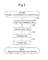
- Fig. 2 is a diagram, namely, a flow chart, which illustrates a method of change-speed operation in the embodiment shown in Fig. 1 .
- Fig. 1 is a diagram for schematically illustrating a power transmission apparatus according to an embodiment of the present invention.
- the power transmission apparatus 1 for hybrid vehicle according to the embodiment is an apparatus in which an engine 91 makes the primary motor and an electric motor 94 makes the secondary motor, and which transmits and outputs a rotary power to a differential device 97.
- the power transmission apparatus 1 is constituted of a power switcher mechanism 2, a first input shaft 3 and a second input shaft 4, a plurality of gear trains 51 through 55 and 5R, an output shaft 6, and an operation controller unit 7.
- the first input shaft 3 is formed as a cylindrical shape
- the second input shaft 4 is formed as a rod shape.
- the first input shaft 3 and second input shaft 4 are arranged coaxially so that the first input shaft 3 comes outside and then the second input shaft 4 comes inside so as to penetrate through the first input shaft 3 leftward in the drawing.
- the first input shaft 3 and second input shaft 4 are made so as to be coupled to the power switcher mechanism 2 selectively at the respective right ends in the drawing.
- the output shaft 6 is arranged so as to run parallel to both of the input shafts 3 and 4 down below both of the input shafts 3 and 4 in the drawing.
- An output gear 61 is disposed integrally at the right end of the output shaft 6 in the drawing.
- the output gear 61 is constituted so as to mesh with an input gear 98 of the differential device 97 and then output a rotary power.
- the first input shaft 3, the second input shaft 4, and the output shaft 6 are supported about the axis rotatably to a not-shown casing by means of not-shown bearing units.
- a rotor 95 of the electric motor 94 is disposed so as to rotate integrally with the first input shaft 3.
- a stator 96 is disposed on an outer-peripheral casing side that faces the rotor 95.
- the stator 96 is constituted so as to give and take an electric power between itself and the operation controller unit 7, and the electric motor 94 doubles as an electric generator. And, when an electric power with prescribed frequency is input into the stator 96 through the operation controller unit 7, the electric motor 94 acts as the secondary motor that rotates at a prescribed revolving speed.
- the electric motor 94 when a rotary power is input into the rotor 95 through the first input shaft 3, the electric motor 94 generates an electric power and then outputs it to the operation controller unit 7.
- the generated electric power is made so as to be supplied to electric loads inside a vehicle after being once stored in a not-shown battery and moreover to be consumed at the time of running that the electric motor 94 drives.
- the power switcher mechanism 2 is a mechanism for transmitting a rotary power of the engine 91 selectively.
- the power switcher mechanism 2 comprises a sleeve 21 that works as the operation switching member.
- a driving-side inner spline 93 is disposed on an outer peripheral side of a primary output shaft 92 of the engine 91.
- the first input shaft 3 and second input shaft 4 are enlarged diametrically at the right ends in the drawing, respectively; and a driven-side first inner spline 31, and a driven-side second inner spline 41 are disposed on their outer peripheral sides, respectively.
- the driven-side first inner spline 31 of the first input shaft 3, and the driven-side second inner spline 41 of the second input shaft 4 are made to have the same specifications, namely, to have an equal diameter and an identical pitch, one another.
- the driven-side first inner spline 31, and the driven-side second inner spline 41 are arranged while providing an interval between them in the axial direction.
- the sleeve 21 is made to have a substantially cylindrical shape, and a driving-side outer spline 22 is disposed on the inner peripheral side of the sleeve 21 on the right in the drawing.
- a driven-side outer spline 23 is disposed on the inner peripheral side of the sleeve 21 on the left in the drawing.
- the driving-side outer spline 22 of the sleeve 21 is fitted into the driving-side inner spline 93 of the primary output shaft 92 at all times.
- the sleeve 21 is made so as to rotate together with the primary output shaft 92, and to be capable of moving in the axial direction.
- the driven-side outer spline 23 of the sleeve 21 fits into the driven-side first inner spline 31 of the first input shaft 3 when it moves in the axial direction to the left in the drawing.
- the driven-side outer spline 23 of the sleeve 21 fits into the driven-side second inner spline 41 of the second input shaft 4 when it moves in the axial direction to the right in the drawing.
- the sleeve 21 is made so as to selectively transmit a rotary power of the engine 91 to each of the input shafts 3 and 4.
- the driven-side outer spline 23 of the sleeve 21 is constituted so that, when it does not move to any of the right and left in the drawing, it is positioned in the middle between the two driven-side inner splines 31 and 41 to make a detached state in which no rotary power is transmitted.
- Fig. 1 illustrates a state where the sleeve 21 is moved in the axial direction to the left in the drawing to transmit a rotary power from the engine 91 to the first input shaft 3.
- the multiple gear trains 51 through 55 and 5R are constituted so that not only they engaged to transmit rotary powers but also they exhibit change-speed ratios differing one another.
- each of driving gears which are arranged on the second input shaft 4 from the left in the drawing, makes a pair with each of driven gears, which are arranged on the output shaft 6 to face the driving gears, to mesh with each other, thereby forming each of the second-speed and fourth-speed gear trains 52 and 54.
- a reverse-travel driving gear which is disposed on the first input shaft 3
- a reverse-travel driven gear which is disposed on the output shaft 6, mesh with each other by way of an intermediate gear, thereby forming a gear train 5R for reverse travel.
- each of the gear trains 51 through 55 and 5R is constituted so that they are engaged selectively by means of a not-shown synchromesh mechanism that has been known publicly.
- the operation controller unit 7 is one which not only controls the revolving speeds of the engine 91 and electric motor 94 but also operates to switch the power switcher mechanism 2.
- the operation controller unit 7 is constituted of an electronic control device, various actuators, various sensors and electric-power supplier unit, which are not shown in the drawing.
- the control for the revolving speed of the engine 91 is carried out by means of detecting a number of rotations of the primary output shaft 92 and then adjusting a fuel-supply amount and/or air-supply amount.
- the control for the revolving speed of the electric motor 94 is carried out by means of supplying an electric power to the electric motor while adjusting the electric power to be supplied from the electric power supplier unit in terms of the frequency or voltage.
- the operation for switching the power switcher mechanism 2 is carried out by means of operating the sleeve 21 with a hydraulic or electric-powered actuator.
- Method for these controls and operations are not limited especially; that is, it is possible to apply techniques, which have been known publicly, to them.
- Fig. 2 is a diagram, namely, a flow chart, which illustrates a method of change-speed operation for the power transmission apparatus 1 for hybrid vehicle according to the embodiment of the present invention.
- the engine 91 is started by means of control through the operation controller unit 7 at the synchronization step P2, and then a revolving speed of the engine 91 is synchronized with respect to that of the second input shaft 4. That is, the engine 91 is synchronized with the output shaft 6 by way of the second input shaft 3 and second-speed gear train 52.
- the power switcher mechanism 2 is coupled to the second input shaft 4 at the paralleling step P3
- a rotary power comes to be transmitted from the engine 91 to the output shaft 6. That is, the engine 91, and the electric motor 94 are operated in parallel.
- an output of the engine 91 is increased at the transfer step P4.
- the rotary power is transferred by means of putting the electric motor 94 in a rest condition eventually, and thereby the change-speed operation is completed.
- a rotary power is transmitted to the output shaft 6 via the first input shaft 3 and third-speed gear train 53, and then the engine 91, and the electric motor 94 are operated in parallel. Subsequently, the rotary power is transferred from the engine 91 to the electric motor 94 at a preliminary transfer step, and thereafter the power switcher mechanism 2 is put in a detached condition. Subsequently, a revolving speed of the engine 91 is synchronized with respect to that of the first input shaft 3 at another synchronization step.
- the power switcher mechanism 2 is coupled to the first input shaft 3 at another paralleling step, then a transmission route, which comes from the engine 91 and then reaches the output shaft 6 via the first input shaft 3 and third-speed gear train 53, is established, and then the engine 91, and the electric motor 94 are operated in parallel. Finally, while decreasing an output of the electric motor 94, an output of the engine 91 is increased at another transfer step. And, the rotary power is transferred by means of putting the electric motor 94 in a rest condition eventually, and thereby the change-speed operation is completed.
- the rotary power is transferred from the engine 91 to the electric motor 94 at another preliminary transfer step, and thereafter the power switcher mechanism 2 is put in a detached condition.
- the fourth-speed gear train 54 where the first input shaft 2 makes the origin, is engaged by means of the synchromesh mechanism at still another gear-train engagement step.
- a revolving speed of the engine 91 is synchronized with respect to that of the second input shaft 4 at still another synchronization step.
- the power switcher mechanism 2 is coupled to the second input shaft 4 at still another paralleling step, then another transmission route, which comes from the engine 91 and then reaches the output shaft 6 via the second input shaft 4 and fourth-speed gear train 54, is established, and then the engine 91, and the electric motor 94 are operated in parallel. Finally, while decreasing an output of the electric motor 94, an output of the engine 91 is increased at still another transfer step. And, the rotary power is transferred by means of putting the electric motor 94 in a rest condition eventually, and thereby the change-speed operation is completed.
- the electric-power generation action of the electric motor 94 is materialized by inputting a rotary power into the first input shaft 3 from the engine 91 directly at the time of running with the gear trains 51, 53 and 55 for odd-numbered speeds. Moreover, at the time of running with the gear trains 52 and 54 for even-numbered speeds, the electric-power generation action of the electric motor 94 is materialized by inputting a rotary power into the first input shaft 3 from the engine 91 by way of the output shaft 6. In addition, even when regenerative energy is generated by means of braking, too, a rotary power is input into the first input shaft 3 by way of the output shaft 6, and thereby the electric-power generation action of the electric motor 94 is materialized.
- the revolving speeds of the engine 91 and electric motor 94 are adjusted by means of direct control through the operation controller unit 7 so that they synchronize with each other. Therefore, in lieu of the conventional friction clutches for establishing the synchronization by means of frictional engagement as having been used heretofore, it is possible to use the power switcher mechanism 2 with a simpler construction that uses the sleeve, and thereby it has become possible to achieve the following: making the apparatus smaller in size; making it lighter in weight; and turning it into an inexpensive one.
Landscapes
- Engineering & Computer Science (AREA)
- Mechanical Engineering (AREA)
- Chemical & Material Sciences (AREA)
- Combustion & Propulsion (AREA)
- Transportation (AREA)
- General Engineering & Computer Science (AREA)
- Automation & Control Theory (AREA)
- Electric Propulsion And Braking For Vehicles (AREA)
- Hybrid Electric Vehicles (AREA)
- Control Of Transmission Device (AREA)
Abstract
[Assignment] To provide a power transmission apparatus for hybrid vehicle, power transmission apparatus which can not only carry out change-speed operations smoothly without ever interrupting the transmission of rotary power while making use of the merit of using a plurality of motors combinedly, and which is but also smaller in size, lighter in weight and more inexpensive than conventional ones; and then to provide a method of change-speed operation for the same.
[Means for Solution] It is equipped with: a power switcher mechanism 2 for selectively transmitting a rotary power of a primary motor (e.g., engine 91; a first input shaft 3, and a second input shaft 4, the first input shaft 3 and the second input shaft 4 that are coupled to the power switcher mechanism 2 selectively, the first input shaft 3 being further connected with a secondary motor (e.g., electric motor 94), the second input shaft 4 being not connected with the secondary motor 94; a plurality of gear trains 51-55 and 5R being placed so that the first input shaft 3 or the second input shaft 4 makes the origin, and making engagements selectively, thereby not only transmitting the rotary power but also exhibiting change-speed ratios that differ one another; an output shaft 6 for outputting the rotary power that the gear trains 51- 55 and 5R transmit; and an operation controller unit 7 for not only controlling a revolving speed of the primary motor 91 and that of the secondary motor 94 but also operating to switch the power switcher mechanism 2.
Description
- The present invention relates to a power transmission apparatus for hybrid vehicle that has a plurality of motors on board; in more detail, it relates to a power transmission apparatus for hybrid vehicle in which a plurality of motors are combined with a transmission being equipped with a plurality of input shafts, and to a method of change-speed operation for the same.
- Hybrid vehicles have come into practical application, hybrid vehicles which have a plurality of motors on board, and that are intended to materialize fuel-consumption improvement, high output and environmental protection by making use of advantages of the respective motors. In particular, hybrid vehicles that have an engine and an electric motor doubling as an electric generator on board have been about to spread rapidly, because they differ from electric automobiles in that they do not require to build any infrastructures such as charging facilities. In general, engines are designed so as to exhibit higher efficiency at economic speed or more, and electric motors doubling as an electric generator are constructed so that, other than they drive running, they generate electric power by making use of engine power and regenerating energy at the time of braking. And, the total efficiency is improved by means of driving hybrid vehicles with the electric motor at the time of starting and at the time of low-speed running and then switching the electric-motor driving to driving with the engine at the moment of being transferred to high-speed running after being accelerated, and thereby the fuel consumption is improved compared with that of vehicles that have an engine alone on board. Moreover, when greater torque is necessary, it is possible to obtain high output by means of driving hybrid vehicles with both the engine and electric motor temporarily. In addition thereto, it is possible to reduce the emission amount of combustion gases to contribute to protecting environments by means of the fuel-consumption improvement and making use of the regenerating energy.
- Meanwhile, as one type of transmissions for vehicle, dual clutch-type automatic transmissions have been available, dual clutch-type automatic transmissions which are equipped with the following: a dual clutch possessing two clutch units; and a plurality of gear trains being constructed between two pieces of input shafts and one piece of output shaft. This transmission has such a merit that it is possible to carry out change-speed operations smoothly so as not to interrupt the transmission of rotary powers by means of carrying out switch-over operations after putting the two clutch units into a semi-joining state. In general, a friction clutch is used for the dual clutch, friction clutch in which a driving-side friction plate and a driven-side friction plate are joined together frictionally to transmit rotary forces; and is controlled automatically by means of an electronic controller and actuator.
- It has been thought of constituting a power transmission apparatus for hybrid vehicle by combining a plurality of motors like those aforementioned and a dual clutch-type automatic transmission, and one of the examples is disclosed in a "Hybrid Vehicle Having Dual Clutch-type Transmission on Board" according to Patent Literature No. 1. In
claim 1 according to Patent Literature No. 1, a construction is disclosed, construction in which a transmission is connected with a crankshaft of engine by way of an electric-powered electric generator and a clutch for changing speeds. The clutch for changing speeds comprises two clutches, and is made so as to be connected odd-numbered gear lines and even-numbered gear lines alternately. Moreover, inclaim 2, another construction is disclosed, another construction which comprises the following: a power switching clutch for connecting and disconnecting engine output; the electric-powered electric generator being formed integrally with the clutch for changing speeds; and multiplate-type friction clutches in a quantity of two pieces. - Patent Literature No. 1: Japanese Unexamined Patent Publication (KOKAI) Gazette No.
2005-329,813 - Incidentally, large-sized vehicles, such as tracks and buses, are subject to the technique according to Patent Literature No. 1 mainly; however, the limitations on the installation of on-board power transmission have been becoming stricter in standard-sized vehicles, such as passenger cars. That is, since the electric-powered electric generator and power switching clutch are added; since two clutches for changing speeds are required to result in being large-sized; and since the transmission proper is provided with two input shafts to result in being large-sized, it has become extremely difficult to have all of these members on-board, compared with general constructions. Moreover, the addition of the members, and their growth in size have declined the efficiency of power transmission to exert adverse effects on the consumption of fuel, and have furthermore become the causes of increasing the costs of the apparatus.
- The present invention is one which has been done in view of the above background; accordingly, it provides a power transmission apparatus for hybrid vehicle, power transmission apparatus which can not only carry out change-speed operations smoothly without ever interrupting the transmission of rotary power while making use of the merit of using a plurality of motors combinedly, and which is but also smaller in size, lighter in weight and more inexpensive than conventional ones; and then it provides a method of change-speed operation for the same.
- A power transmission apparatus for hybrid vehicle according to the present invention is characterized in that it is equipped with:
- a power switcher mechanism for selectively transmitting a rotary power of a primary motor;
- a first input shaft, and a second input shaft, the first input shaft and the second input shaft that are coupled to the power switcher mechanism selectively, the first input shaft being further connected with a secondary motor, the second input shaft being not connected with the secondary motor;
- a plurality of gear trains being placed so that the first input shaft or the second input shaft makes the origin, and making engagements selectively, thereby not only transmitting the rotary power but also exhibiting change-speed ratios that differ one another;
- an output shaft for outputting the rotary power that the gear trains transmit; and
- an operation controller unit for not only controlling a revolving speed of the primary motor and that of the secondary motor but also operating to switch the power switcher mechanism.
- It is the gist of the present invention to make the frictional synchronizing operation using a dual clutch obsolete and then to simplify the construction of the apparatus by means of the following: not only coupling between the primary motor and the first input shaft, and between the primary motor and the second input shaft, with the power switcher mechanism selectively; but also connecting the secondary motor with the first input shaft at all times; and then controlling the revolving speeds of the primary motor and secondary motor by directly controlling through the operation controller unit. Note that the "first" and "second" distinctions for the input shafts are those which are put on them, respectively, in order for identifying one of the input shafts that is connected with the secondary motor.
- It is preferable that:
- said primary motor can be an engine; and
- said secondary motor can be an electric motor that doubles as an electric generator.
- By means of adapting the primary motor into an engine, it is possible to use all of the gear trains, where the first input shaft or the second input shaft makes the origin, for engine drive. That is, in the ordinary running by means of engine drive, it is possible to select any change-speed ratios that the gear trains exhibit. Moreover, by means of adapting the secondary motor into an electric motor doubling as an electric generator, it is possible to use one of the gear trains, where the first input shaft makes the origin, for electric-motor drive. In addition, by means of inputting the engine's motive power, or regenerating energy at the time of braking, from the first input shaft into the electric motor doubling as an electric generator, it is possible to generate electric power.
- It is preferable that a first-speed gear train of said gear trains can be placed so that the first input shaft being connected with said electric motor makes the origin.
- In accordance with the aforementioned mode, the starting and low-speed running, which the first-speed gear train does, by electric-motor drive; accordingly, it is possible to compensate the disadvantage of engine drive where the efficiency at the time of low speed is lower; consequently, the mode becomes effective for the improvement of total efficiency.
- It is even allowable to set up said power switcher mechanism so that it can comprise an operation switching member that rotates together with a primary output shaft of the primary motor, and which is disposed movably in an axial direction and is coupled to one of said first input shaft and said second input shaft when being moved in the axial direction.
- In addition, it is preferable that:
- said primary output shaft of said primary motor can comprise a driving-side inner spline on its outer peripheral side;
- said first input shaft can comprise a driven-side first inner spline on its outer peripheral side;
- said second input shaft can comprise a driven-side second inner spline on its outer peripheral side; and
- said operation switching member can be a sleeve comprising a driving-side outer spline, which fits into the driving-side inner spline, on its inner peripheral side, and a driven-side outer spline, which fits into one of the driven-side first inner spline and the driven-side second inner spline selectively, thereon.
- It is possible to construct the power switcher mechanism so that it is adapted into a sleeve rotating together with a primary output shaft of the primary motor, and being held movably in an axial direction by spline fitting; and that the sleeve fits into the first input shaft or the second input shaft selectively. In this mode, the operation controller unit controls the revolving speed of the primary motor in advance so that it synchronizes with respect to that of one of the input shafts into which the sleeve is to be fitted, prior to a fitting operation in which the sleeve is moved in the axial direction. The power switcher mechanism using the sleeve is simple remarkably, compared with the conventional construction being exemplified in Patent Literature No. 1, that is, one which uses a power switching clutch and a clutch for changing speeds combinedly; and accordingly it is possible to make it in smaller size, lighter in weight, and inexpensively. Note that the powder switcher mechanism is not limited to this mode; consequently it is possible to use dog clutches, which have been known publicly, for instance.
- It is even permissible that:
- one of said first input shaft and said second input shaft can make a rod shape;
- another one of them can make a cylindrical shape; and
- they can be arranged coaxially so that the one of them comes inside and the other one of them comes outside.
- From the viewpoints of reducing in size and lightening in weight, it is preferable that the two input shafts can be arranged coaxially so that one of them comes inside and the other one of them comes outside; and it is even allowable that the secondary motor can be connected with either one of the input shafts that comes inside or outside. Note that it is even possible to arrange the two input shafts in parallel with each other.
- A method of change-speed operation according to the present invention, whose subject is the above-described power transmission apparatus for hybrid vehicle, is characterized in that it comprises:
- a gear-train engagement step of being engaged with a new second gear train when the rotary power is transmitted from one of said primary motor and said secondary motor to said output shaft via a first gear train of said gear trains;
- a synchronization step of synchronizing another one of the primary motor and the secondary motor with the output shaft by way of the second gear train by means of control through said operation controller unit;
- a paralleling step of transmitting the rotary power from both of the primary motor and the secondary motor to the output shaft; and
- a transfer step of transferring the rotary power from the one of the primary motor and the secondary motor to the other one of them.
- The method of change-speed operation according to the present invention comprises four steps, the gear-train engagement step, the synchronization step, the paralleling step and the transfer step, basically; depending on combinations of the motors, input shafts and gear trains that are employed before and after change-speed operations, the following variations are derived as being exemplified below.
- It is even allowable that the method of change-speed operation according to the present invention can comprise:
- a gear-train engagement step of being engaged with a new second gear train in which said second input shaft makes the origin when the power switcher mechanism is put in a detached state where being not coupled to the first input shaft or the second input shaft, and when the rotary power is transmitted from said secondary motor and up to said output shaft via said first input shaft and a first gear train of said gear trains;
- a synchronization step of synchronizing said primary motor with respect to the second input shaft by means of control through said operation controller unit;
- a paralleling step of coupling the power switcher mechanism to the second input shaft, thereby establishing a transmission route that comes from the primary motor and then reaches the output shaft via the second input shaft and the second gear train; and
- a transfer step of transferring the rotary power from the secondary motor to the primary motor.
- When shifting a driving source from the secondary motor to the primary motor, it is possible to finish the change-speed operation by the basic four steps. When the second gear train is engaged by means of the gear-train engagement step, the second input shaft is coupled to the output shaft, and then comes to be driven from the output-shaft side. Therefore, the operation of synchronizing the primary motor with respect to the second input shaft in the synchronization step comes to have the same meaning as the operation of synchronizing the primary motor with the output shaft by way of the second gear train. Moreover, when the power switcher mechanism is coupled to the second input shaft at the paralleling step, the output shaft is driven by both of the secondary motor and the primary motor, and then becomes a state of being operated in parallel temporarily. The rotary power is transferred by means of increasing an output of the primary motor from that in the state of being operated in parallel while stopping the secondary motor in the transfer step. Note that, when shifting a driving source from the primary motor to the secondary motor, too, it is possible to finish the change-speed operation by the same four steps.
- It is even permissible that the method of change-speed operation according to the present invention can comprise:
- a gear-train engagement step of being engaged with a new fourth gear train in which said first input shaft makes the origin when said secondary motor is put in a rest condition, and when said power switcher mechanism is coupled to said second input shaft so that the rotary power is transmitted from said primary motor and up to the output shaft via said second input shaft and a third gear train of said gear trains;
- a preliminary synchronization-paralleling step of not only starting the secondary motor to synchronize it with respect to the first input shaft but also establishing a transmission route that comes from the secondary motor and then reaches the output shaft via the first input shaft and the fourth gear train;
- a preliminary transfer step of transferring the rotary power from the primary motor to the secondary motor, and thereafter putting the power switcher mechanism in a detached state where being not coupled to the first input shaft or the second input shaft;
- a synchronization step of synchronizing the primary motor with respect to the first input shaft by means of control through said operation controller unit;
- a paralleling step of coupling the power switcher mechanism to the first input shaft, thereby establishing a transmission route that comes from the primary motor and then reaches the output shaft via the first input shaft and the fourth gear train; and
- a transfer step of transferring the rotary power from the secondary motor to the primary motor again.
- Moreover, it is even allowable that the method of change-speed operation according to the present invention can comprise:
- a preliminary synchronization-paralleling step of not only starting said secondary motor to synchronize it with respect to said first input shaft but also establishing a transmission route that comes from the secondary motor and then reaches said output shaft via the first input shaft and a fifth gear train of said gear trans when the secondary motor is put in a rest condition, and when said power switcher mechanism is coupled to the first input shaft so that the rotary power is transmitted from said primary motor and up to the output shaft via the first input shaft and the fifth gear train;
- a preliminary transfer step of putting the power switcher mechanism in a detached state where being not coupled to the first input shaft or the second input shaft after the rotary power is transferred from the primary motor to the secondary motor;
- a gear-train formation step of forming a new sixth gear train in which the second input shaft makes the origin;
- a synchronization step of synchronizing the primary motor with respect to the second input shaft by means of control through said operation controller unit;
- a paralleling step of coupling the power switcher mechanism to the second input shaft, thereby establishing a transmission route that comes from the primary motor and then reaches the output shaft via the second input shaft and the sixth gear train; and
- a transfer step of transferring the rotary power from the secondary motor to the primary motor again.
- When shifting the input shafts for transmitting the rotary power from one of them to the other one of them while keeping the primary motor making a driving source as it is before and after the change-speed operation, the number of steps increases, because it turns into an operation of returning the rotary power to the primary motor after transferring the rotary power to the secondary motor once and then operating the input shafts to switch between one of them and the other of them that is to be coupled to the power switcher mechanism. Moreover, the changes arise in the contents of the respective steps, depending on either of which input shafts makes the origin in the gear trains before and after the change-speed operation.
- In addition, it is possible to carry out not only the pass-over or unsequential change-speed operation that is done while passing over any intermediate change-speed stages but also the operation of being operated in parallel that is driven by both of the motors.
- The power transmission apparatus for hybrid vehicle according to the present invention is made so that: not only the power switcher mechanism couples between the primary motor and the first input shaft, and between the primary motor and the second input shaft, selectively; but also the secondary motor is connected with the first input shaft at all times; and then the revolving speeds of the primary motor and secondary motor are controlled through the operation controller unit directly. Therefore, it is possible to materialize a simple apparatus in which it is not necessary to carry out the frictional synchronizing operation using any dual clutch, and that carries out change-speed operations smoothly without ever interrupting the transmission of rotary power.
- Moreover, in the mode in which an engine makes the primary motor and an electric motor doubling as an electric generator makes the secondary motor, it is possible to use all of the gear trains for engine drive; it is possible to use one of the gear trains in which the first input shaft makes the origin for electric-motor drive; and then it is possible to generate electric power by means of inputting engine power and regenerating energy at the time of braking into the electric motor doubling as an electric generator through the first input shaft. That is, even when the construction of apparatus is simplified, it has been possible to give the apparatus the characteristic functions of dual clutch, namely, not interrupting the transmission of rotary power, while maintaining the same functions as those of conventional hybrid vehicles.
- In addition, the mode, where the first-speed gear train of said gear trains is placed so that the first input shaft being connected with the electric motor makes the origin, is effective in the improvement of total efficiency, because it is possible to carry out the starting and low-speed running, which the first-speed gear train does, by electric-motor drive.
- Moreover, the mode, where a sleeve that rotates together with the a primary output shaft of the primary motor and which is retained thereto movably in the axial direction by fitting with spline is used as the power switcher mechanism, is simple remarkably, compared with the conventional construction that uses a power switching clutch and a clutch for changing speeds combinedly; and consequently it can be made in smaller size, lighter in weight, and inexpensively.
-
Fig. 1 is a schematic diagram, which schematically illustrates a power transmission apparatus according to an embodiment of the present invention; andFig. 2 is a diagram, namely, a flow chart, which illustrates a method of change-speed operation in the embodiment shown inFig. 1 . - One of the best modes for executing the present invention will be explained with reference to
Fig. 1 andFig. 2 .Fig. 1 is a diagram for schematically illustrating a power transmission apparatus according to an embodiment of the present invention. Thepower transmission apparatus 1 for hybrid vehicle according to the embodiment is an apparatus in which anengine 91 makes the primary motor and anelectric motor 94 makes the secondary motor, and which transmits and outputs a rotary power to adifferential device 97. Thepower transmission apparatus 1 is constituted of apower switcher mechanism 2, afirst input shaft 3 and asecond input shaft 4, a plurality ofgear trains 51 through 55 and 5R, anoutput shaft 6, and anoperation controller unit 7. - The
first input shaft 3 is formed as a cylindrical shape, and thesecond input shaft 4 is formed as a rod shape. Thefirst input shaft 3 andsecond input shaft 4 are arranged coaxially so that thefirst input shaft 3 comes outside and then thesecond input shaft 4 comes inside so as to penetrate through thefirst input shaft 3 leftward in the drawing. As will be described later, thefirst input shaft 3 andsecond input shaft 4 are made so as to be coupled to thepower switcher mechanism 2 selectively at the respective right ends in the drawing. Theoutput shaft 6 is arranged so as to run parallel to both of theinput shafts input shafts output gear 61 is disposed integrally at the right end of theoutput shaft 6 in the drawing. Theoutput gear 61 is constituted so as to mesh with aninput gear 98 of thedifferential device 97 and then output a rotary power. Note that thefirst input shaft 3, thesecond input shaft 4, and theoutput shaft 6 are supported about the axis rotatably to a not-shown casing by means of not-shown bearing units. - On the outer peripheral side of the
first input shaft 3 adjacent to the right end in the drawing, arotor 95 of theelectric motor 94 is disposed so as to rotate integrally with thefirst input shaft 3. Meanwhile, astator 96 is disposed on an outer-peripheral casing side that faces therotor 95. Thestator 96 is constituted so as to give and take an electric power between itself and theoperation controller unit 7, and theelectric motor 94 doubles as an electric generator. And, when an electric power with prescribed frequency is input into thestator 96 through theoperation controller unit 7, theelectric motor 94 acts as the secondary motor that rotates at a prescribed revolving speed. Conversely, when a rotary power is input into therotor 95 through thefirst input shaft 3, theelectric motor 94 generates an electric power and then outputs it to theoperation controller unit 7. The generated electric power is made so as to be supplied to electric loads inside a vehicle after being once stored in a not-shown battery and moreover to be consumed at the time of running that theelectric motor 94 drives. - The
power switcher mechanism 2 is a mechanism for transmitting a rotary power of theengine 91 selectively. Thepower switcher mechanism 2 comprises asleeve 21 that works as the operation switching member. When being described in detail, a driving-sideinner spline 93 is disposed on an outer peripheral side of aprimary output shaft 92 of theengine 91. Thefirst input shaft 3 andsecond input shaft 4 are enlarged diametrically at the right ends in the drawing, respectively; and a driven-side firstinner spline 31, and a driven-side secondinner spline 41 are disposed on their outer peripheral sides, respectively. The driven-side firstinner spline 31 of thefirst input shaft 3, and the driven-side secondinner spline 41 of thesecond input shaft 4 are made to have the same specifications, namely, to have an equal diameter and an identical pitch, one another. As shown in the drawing, the driven-side firstinner spline 31, and the driven-side secondinner spline 41 are arranged while providing an interval between them in the axial direction. Meanwhile, thesleeve 21 is made to have a substantially cylindrical shape, and a driving-sideouter spline 22 is disposed on the inner peripheral side of thesleeve 21 on the right in the drawing. A driven-sideouter spline 23 is disposed on the inner peripheral side of thesleeve 21 on the left in the drawing. The driving-sideouter spline 22 of thesleeve 21 is fitted into the driving-sideinner spline 93 of theprimary output shaft 92 at all times. Thesleeve 21 is made so as to rotate together with theprimary output shaft 92, and to be capable of moving in the axial direction. The driven-sideouter spline 23 of thesleeve 21 fits into the driven-side firstinner spline 31 of thefirst input shaft 3 when it moves in the axial direction to the left in the drawing. Moreover, the driven-sideouter spline 23 of thesleeve 21 fits into the driven-side secondinner spline 41 of thesecond input shaft 4 when it moves in the axial direction to the right in the drawing. Thus, thesleeve 21 is made so as to selectively transmit a rotary power of theengine 91 to each of theinput shafts outer spline 23 of thesleeve 21 is constituted so that, when it does not move to any of the right and left in the drawing, it is positioned in the middle between the two driven-sideinner splines Fig. 1 illustrates a state where thesleeve 21 is moved in the axial direction to the left in the drawing to transmit a rotary power from theengine 91 to thefirst input shaft 3. - The
multiple gear trains 51 through 55 and 5R are constituted so that not only they engaged to transmit rotary powers but also they exhibit change-speed ratios differing one another. Each of driving gears (not designated with reference numbers), which are arranged on thefirst input shaft 3 from the left in the drawing, makes a pair with each of driven gears (not designated with reference numbers), which are arranged on theoutput shaft 6 to face the driving gears, to mesh with each other, thereby forming each of the first-speed, third-speed and fifth-speed gear trains second input shaft 4 from the left in the drawing, makes a pair with each of driven gears, which are arranged on theoutput shaft 6 to face the driving gears, to mesh with each other, thereby forming each of the second-speed and fourth-speed gear trains first input shaft 3, and a reverse-travel driven gear, which is disposed on theoutput shaft 6, mesh with each other by way of an intermediate gear, thereby forming agear train 5R for reverse travel. Note that each of thegear trains 51 through 55 and 5R is constituted so that they are engaged selectively by means of a not-shown synchromesh mechanism that has been known publicly. - The
operation controller unit 7 is one which not only controls the revolving speeds of theengine 91 andelectric motor 94 but also operates to switch thepower switcher mechanism 2. Theoperation controller unit 7 is constituted of an electronic control device, various actuators, various sensors and electric-power supplier unit, which are not shown in the drawing. The control for the revolving speed of theengine 91 is carried out by means of detecting a number of rotations of theprimary output shaft 92 and then adjusting a fuel-supply amount and/or air-supply amount. The control for the revolving speed of theelectric motor 94 is carried out by means of supplying an electric power to the electric motor while adjusting the electric power to be supplied from the electric power supplier unit in terms of the frequency or voltage. Moreover, the operation for switching thepower switcher mechanism 2 is carried out by means of operating thesleeve 21 with a hydraulic or electric-powered actuator. Method for these controls and operations are not limited especially; that is, it is possible to apply techniques, which have been known publicly, to them. - Next, an operation method and actions of the
power transmission apparatus 1 for hybrid vehicle according to the above-described embodiment will be explained hereinafter. Firstly, an operation method of starting vehicle from the state of standstill will be explained. When a vehicle is in the state of standstill, theengine 91 andelectric motor 94 are stopped, thepower switcher mechanism 2 is put in a detached state, and none of thegear trains 51 through 55 and 5R are engaged. Under the circumstances, the first-speed gear train 51, where thefirst input shaft 3 makes the origin, is first engaged by means of the synchromesh mechanism. Subsequently, when theoperation controller unit 7 supplies an electric power to theelectric motor 94 from the electric-power supplier unit, theelectric motor 94 starts, and then thefirst input shaft 3 begins to rotate. And, a rotary power is output to thedifferential device 97 from theoutput shaft 6 by way of the first-speed gear train 51. Thus, the vehicle starts and then runs at the first speed. - Successively, an operation of up-shifting change-speed from the first speed by driving with the
electric motor 94 to the second speed by driving with theengine 91 will be explained with reference toFig. 2. Fig. 2 is a diagram, namely, a flow chart, which illustrates a method of change-speed operation for thepower transmission apparatus 1 for hybrid vehicle according to the embodiment of the present invention. When a change-speed request to the second speed arises during the first-speed running, the second-speed gear train 52, where thesecond input shaft 4 makes the origin, is first engaged by means of the synchromesh mechanism at the gear-train engagement step P1. Subsequently, theengine 91 is started by means of control through theoperation controller unit 7 at the synchronization step P2, and then a revolving speed of theengine 91 is synchronized with respect to that of thesecond input shaft 4. That is, theengine 91 is synchronized with theoutput shaft 6 by way of thesecond input shaft 3 and second-speed gear train 52. Subsequently, when thepower switcher mechanism 2 is coupled to thesecond input shaft 4 at the paralleling step P3, a rotary power comes to be transmitted from theengine 91 to theoutput shaft 6. That is, theengine 91, and theelectric motor 94 are operated in parallel. Finally, while decreasing an output of theelectric motor 94, an output of theengine 91 is increased at the transfer step P4. And, the rotary power is transferred by means of putting theelectric motor 94 in a rest condition eventually, and thereby the change-speed operation is completed. - Successively, a change-speed operation from the second speed by driving with the
engine 91 to the third speed by driving with theengine 91 will be explained. When a change-speed request to the third speed arises during the second-speed running, the third-speed gear train 53, where thefirst input shaft 3 makes the origin, is first engaged by means of the synchromesh mechanism at another gear-train engagement step. Subsequently, theelectric motor 94 is started at a preliminary synchronization-paralleling step, and then a revolving speed of theelectric motor 94 is synchronized with respect to that of thefirst input shaft 3. That is, from theelectric motor 94 as well, a rotary power is transmitted to theoutput shaft 6 via thefirst input shaft 3 and third-speed gear train 53, and then theengine 91, and theelectric motor 94 are operated in parallel. Subsequently, the rotary power is transferred from theengine 91 to theelectric motor 94 at a preliminary transfer step, and thereafter thepower switcher mechanism 2 is put in a detached condition. Subsequently, a revolving speed of theengine 91 is synchronized with respect to that of thefirst input shaft 3 at another synchronization step. Subsequently, thepower switcher mechanism 2 is coupled to thefirst input shaft 3 at another paralleling step, then a transmission route, which comes from theengine 91 and then reaches theoutput shaft 6 via thefirst input shaft 3 and third-speed gear train 53, is established, and then theengine 91, and theelectric motor 94 are operated in parallel. Finally, while decreasing an output of theelectric motor 94, an output of theengine 91 is increased at another transfer step. And, the rotary power is transferred by means of putting theelectric motor 94 in a rest condition eventually, and thereby the change-speed operation is completed. - Successively, a change-speed operation from the third speed by driving with the
engine 91 to the fourth speed by driving with theengine 91 will be explained. When a change-speed request to the fourth speed arises during the third-speed running, theelectric motor 94 is started at another preliminary synchronization-paralleling step, and then a revolving speed of theelectric motor 94 is synchronized with respect to that of thefirst input shaft 3. That is, from theelectric motor 94 as well, a rotary power is transmitted to theoutput shaft 6 via thefirst input shaft 3 and third-speed gear train 53, and then theengine 91, and theelectric motor 94 are operated in parallel. Subsequently, the rotary power is transferred from theengine 91 to theelectric motor 94 at another preliminary transfer step, and thereafter thepower switcher mechanism 2 is put in a detached condition. Subsequently, the fourth-speed gear train 54, where thefirst input shaft 2 makes the origin, is engaged by means of the synchromesh mechanism at still another gear-train engagement step. Subsequently, a revolving speed of theengine 91 is synchronized with respect to that of thesecond input shaft 4 at still another synchronization step. Subsequently, thepower switcher mechanism 2 is coupled to thesecond input shaft 4 at still another paralleling step, then another transmission route, which comes from theengine 91 and then reaches theoutput shaft 6 via thesecond input shaft 4 and fourth-speed gear train 54, is established, and then theengine 91, and theelectric motor 94 are operated in parallel. Finally, while decreasing an output of theelectric motor 94, an output of theengine 91 is increased at still another transfer step. And, the rotary power is transferred by means of putting theelectric motor 94 in a rest condition eventually, and thereby the change-speed operation is completed. - Note hereinafter that it is possible to carry out still another change-speed operation of up-shifting from the fourth speed to the fifth speed as well in the same manner as the change-speed operation from the second speed to the third speed. Moreover, it is possible to carry out operations of down-shifting from higher-speed sides to likewise lower-speed sides as well as pass-over or unsequential change-speed operations.
- Note that the electric-power generation action of the
electric motor 94 is materialized by inputting a rotary power into thefirst input shaft 3 from theengine 91 directly at the time of running with thegear trains gear trains electric motor 94 is materialized by inputting a rotary power into thefirst input shaft 3 from theengine 91 by way of theoutput shaft 6. In addition, even when regenerative energy is generated by means of braking, too, a rotary power is input into thefirst input shaft 3 by way of theoutput shaft 6, and thereby the electric-power generation action of theelectric motor 94 is materialized. - As explained above, in the present embodiment, the revolving speeds of the
engine 91 andelectric motor 94 are adjusted by means of direct control through theoperation controller unit 7 so that they synchronize with each other. Therefore, in lieu of the conventional friction clutches for establishing the synchronization by means of frictional engagement as having been used heretofore, it is possible to use thepower switcher mechanism 2 with a simpler construction that uses the sleeve, and thereby it has become possible to achieve the following: making the apparatus smaller in size; making it lighter in weight; and turning it into an inexpensive one. -
- 1: Power
- Transmission Apparatus for Hybrid Vehicle;
- 2:
- Power Switcher Mechanism; 21: Sleeve;
- 3:
- First Input Shaft;
- 4:
- Second Input Shaft;
- 51-55:
- Gear Trains for First Speed-Fifth Speed;
- 5R:
- Gear Train for Reverse Travel;
- 6:
- Output Shaft;
- 7:
- Operation Controller Unit
- 91:
- Engine; 94: Electric Motor; and
- 97;
- Differential Device
Claims (10)
- A power transmission apparatus for hybrid vehicle being characterized in that it is equipped with:a power switcher mechanism for selectively transmitting a rotary power of a primary motor;a first input shaft, and a second input shaft, the first input shaft and the second input shaft that are coupled to the power switcher mechanism selectively, the first input shaft being further connected with a secondary motor, the second input shaft being not connected with the secondary motor;a plurality of gear trains being placed so that the first input shaft or the second input shaft makes the origin, and making engagements selectively, thereby not only transmitting the rotary power but also exhibiting change-speed ratios that differ one another;an output shaft for outputting the rotary power that the gear trains transmit; andan operation controller unit for not only controlling a revolving speed of the primary motor and that of the secondary motor but also operating to switch the power switcher mechanism.
- The power transmission apparatus for hybrid vehicle as set forth in claim 1, wherein:said primary motor is an engine; andsaid secondary motor is an electric motor that doubles as an electric generator.
- The power transmission apparatus for hybrid vehicle as set forth in claim 2, wherein a first-speed gear train of said gear trains is placed so that the first input shaft being connected with said electric motor makes the origin.
- The power transmission apparatus for hybrid vehicle as set forth in either one of claims 1-3, wherein said power switcher mechanism comprises an operation switching member that rotates together with a primary output shaft of the primary motor, and which is disposed movably in an axial direction and is coupled to one of said first input shaft and said second input shaft when being moved in the axial direction.
- The power transmission apparatus for hybrid vehicle as set forth in claim 4, wherein:said primary output shaft of said primary motor comprises a driving-side inner spline on its outer peripheral side;said first input shaft comprises a driven-side first inner spline on its outer peripheral side;said second input shaft comprises a driven-side second inner spline on its outer peripheral side; andsaid operation switching member is a sleeve comprising a driving-side outer spline, which fits into the driving-side inner spline, on its inner peripheral side, and a driven-side outer spline, which fits into one of the driven-side first inner spline and the driven-side second inner spline selectively, thereon.
- The power transmission apparatus for hybrid vehicle as set forth in either one of claims 1-5, wherein:one of said first input shaft and said second input shaft makes a rod shape;another one of them makes a cylindrical shape; andthey are arranged coaxially so that the one of them comes inside and the other one of them comes outside.
- A method of change-speed operation for power transmission apparatus for hybrid vehicle being a method of change-speed operation for the power transmission apparatus for hybrid vehicle as set forth in either of one of claims 1-6, and being characterized in that it comprises:a gear-train engagement step of being engaged with a new second gear train when the rotary power is transmitted from one of said primary motor and said secondary motor to said output shaft via a first gear train of said gear trains;a synchronization step of synchronizing another one of the primary motor and the secondary motor with the output shaft by way of the second gear train by means of control through said operation controller unit;a paralleling step of transmitting the rotary power from both of the primary motor and the secondary motor to the output shaft; anda transfer step of transferring the rotary power from the one of the primary motor and the secondary motor to the other one of them.
- The method of change-speed operation for power transmission apparatus for hybrid vehicle as set forth in claim 7 comprising:a gear-train engagement step of being engaged with a new second gear train in which said second input shaft makes the origin when the power switcher mechanism is put in a detached state where being not coupled to the first input shaft or the second input shaft, and when the rotary power is transmitted from said secondary motor and up to said output shaft via said first input shaft and a first gear train of said gear trains;a synchronization step of synchronizing said primary motor with respect to the second input shaft by means of control through said operation controller unit;a paralleling step of coupling the power switcher mechanism to the second input shaft, thereby establishing a transmission route that comes from the primary motor and then reaches the output shaft via the second input shaft and the second gear train; anda transfer step of transferring the rotary power from the secondary motor to the primary motor.
- The method of change-speed operation for power transmission apparatus for hybrid vehicle as set forth in claim 7 comprising:a gear-train engagement step of being engaged with a new fourth gear train in which said first input shaft makes the origin when said secondary motor is put in a rest condition, and when said power switcher mechanism is coupled to said second input shaft so that the rotary power is transmitted from said primary motor and up to the output shaft via said second input shaft and a third gear train of said gear trains;a preliminary synchronization-paralleling step of not only starting the secondary motor to synchronize it with respect to the first input shaft but also establishing a transmission route that comes from the secondary motor and then reaches the output shaft via the first input shaft and the fourth gear train;a preliminary transferring step of transferring the rotary power from the primary motor to the secondary motor, and thereafter putting the power switcher mechanism in a detached state where being not coupled to the first input shaft or the second input shaft;a synchronization step of synchronizing the primary motor with respect to the first input shaft by means of control through said operation controller unit;a paralleling step of coupling the power switcher mechanism to the first input shaft, thereby establishing a transmission route that comes from the primary motor and then reaches the output shaft via the first input shaft and the fourth gear train; anda transfer step of transferring the rotary power from the secondary motor to the primary motor again.
- The method of change-speed operation for power transmission apparatus for hybrid vehicle as set forth in claim 7 comprising:a preliminary synchronization-paralleling step of not only starting said secondary motor to synchronize it with respect to said first input shaft but also establishing a transmission route that comes from the secondary motor and then reaches said output shaft via the first input shaft and a fifth gear train of said gear trans when the secondary motor is put in a rest condition, and when said power switcher mechanism is coupled to the first input shaft so that the rotary power is transmitted from said primary motor and up to the output shaft via the first input shaft and the fifth gear train;a preliminary transfer step of putting the power switcher mechanism in a detached state where being not coupled to the first input shaft or the second input shaft after the rotary power is transferred from the primary motor to the secondary motor;a gear-train formation step of forming a new sixth gear train in which the second input shaft makes the origin;a synchronization step of synchronizing the primary motor with respect to the second input shaft by means of control through said operation controller unit;a paralleling step of coupling the power switcher mechanism to the second input shaft, thereby establishing a transmission route that comes from the primary motor and then reaches the output shaft via the second input shaft and the sixth gear train; anda transfer step of transferring the rotary power from the secondary motor to the primary motor again.
Applications Claiming Priority (2)
| Application Number | Priority Date | Filing Date | Title |
|---|---|---|---|
| JP2008145852A JP2009292215A (en) | 2008-06-03 | 2008-06-03 | Power transmission device for hybrid vehicle and gear shift operation method thereof |
| PCT/JP2009/059990 WO2009148019A1 (en) | 2008-06-03 | 2009-06-01 | Power transmission device for hybrid vehicle and speed change operation method thereof |
Publications (1)
| Publication Number | Publication Date |
|---|---|
| EP2281727A1 true EP2281727A1 (en) | 2011-02-09 |
Family
ID=41398096
Family Applications (1)
| Application Number | Title | Priority Date | Filing Date |
|---|---|---|---|
| EP09758286A Withdrawn EP2281727A1 (en) | 2008-06-03 | 2009-06-01 | Power transmission device for hybrid vehicle and speed change operation method thereof |
Country Status (4)
| Country | Link |
|---|---|
| US (1) | US20110073393A1 (en) |
| EP (1) | EP2281727A1 (en) |
| JP (1) | JP2009292215A (en) |
| WO (1) | WO2009148019A1 (en) |
Cited By (6)
| Publication number | Priority date | Publication date | Assignee | Title |
|---|---|---|---|---|
| WO2012000706A1 (en) * | 2010-06-28 | 2012-01-05 | Zf Friedrichshafen Ag | Hybrid drive of a motor vehicle and method for controlling same |
| WO2012131259A1 (en) * | 2011-04-01 | 2012-10-04 | Renault S.A.S. | Hybrid transmission for a motor vehicle, and control method |
| WO2013001194A1 (en) * | 2011-06-28 | 2013-01-03 | Renault S.A.S. | Electrical architecture of a hybrid vehicle, hybrid vehicle and control method |
| WO2013087054A1 (en) * | 2011-12-13 | 2013-06-20 | Schaeffler Technologies AG & Co. KG | Drive train having a dual clutch gear and method for controlling same |
| WO2013091968A1 (en) * | 2011-12-21 | 2013-06-27 | Zf Friedrichshafen Ag | Hybrid drive of a motor vehicle and method for operating same |
| WO2020239424A1 (en) * | 2019-05-29 | 2020-12-03 | Daimler Ag | Hybrid drive system and shifting method |
Families Citing this family (19)
| Publication number | Priority date | Publication date | Assignee | Title |
|---|---|---|---|---|
| JP5498706B2 (en) * | 2009-02-04 | 2014-05-21 | アイシン・エーアイ株式会社 | Hybrid power transmission device |
| CN102221082A (en) * | 2010-11-30 | 2011-10-19 | 长城汽车股份有限公司 | Stepless gearshift of automobile AMT (Advanced Manufacturing Technology) speed changer |
| US10677296B2 (en) * | 2010-12-10 | 2020-06-09 | Means Industries, Inc. | Electronic, high-efficiency vehicular transmission, overrunning, non-friction coupling and control assembly and switchable linear actuator device for use therein |
| EP2468553A1 (en) * | 2010-12-21 | 2012-06-27 | Saab Automobile AB | A vehicle powertrain arrangement |
| DE102011005561A1 (en) * | 2011-03-15 | 2012-09-20 | Zf Friedrichshafen Ag | Manual transmission of a hybrid drive for a motor vehicle |
| FR3004776B1 (en) * | 2013-04-17 | 2015-04-10 | Renault Sa | METHOD FOR CONTROLLING THE CRABOTAGE OF A GEARBOX |
| CN103223860B (en) * | 2013-04-18 | 2015-11-25 | 吉林大学 | For the plug-in hybrid driving device of family-sized car |
| JP6026990B2 (en) * | 2013-12-02 | 2016-11-16 | 本田技研工業株式会社 | Vehicle drive device |
| CN103818230A (en) * | 2014-02-26 | 2014-05-28 | 南京越博汽车电子有限公司 | AMT clutch control system and method of single-shaft parallel hybrid electric vehicle |
| US10781920B2 (en) * | 2014-09-16 | 2020-09-22 | Means Industries, Inc. | Drive systems including transmissions and magnetic coupling devices for electric and hybrid electric vehicles |
| US10781891B2 (en) | 2014-09-16 | 2020-09-22 | Means Industries, Inc. | Drive system including a transmission and magnetic coupling device for an electric vehicle |
| KR101637686B1 (en) * | 2014-09-29 | 2016-07-08 | 현대자동차주식회사 | Hybrid transmission for vehicle |
| JP6343596B2 (en) * | 2015-10-06 | 2018-06-13 | 本田技研工業株式会社 | Dual clutch transmission |
| US20210309097A1 (en) * | 2018-09-21 | 2021-10-07 | Schaeffler Technologies AG & Co. KG | Hybrid power transmission and hybrid power vehicle |
| CN111486230B (en) * | 2019-01-29 | 2022-04-08 | 宇通客车股份有限公司 | Vehicle, power system and gear shifting method with uninterrupted gear shifting power |
| DE102019202972A1 (en) * | 2019-03-05 | 2020-09-10 | Zf Friedrichshafen Ag | Hybrid transmission device and motor vehicle |
| DE102019205510A1 (en) * | 2019-04-16 | 2020-10-22 | Zf Friedrichshafen Ag | Hybrid transmission device, motor-transmission arrangement, hybrid drive train and motor vehicle |
| US11541861B2 (en) * | 2019-04-30 | 2023-01-03 | Borgwarner Inc. | Transmission system for use in a vehicle |
| CN110816247A (en) * | 2019-09-30 | 2020-02-21 | 潍柴动力股份有限公司 | Hybrid power system and control method thereof |
Family Cites Families (18)
| Publication number | Priority date | Publication date | Assignee | Title |
|---|---|---|---|---|
| JPS601427A (en) * | 1983-06-15 | 1985-01-07 | Daikin Mfg Co Ltd | Power switching device for vehicle and the like for industrial machine |
| US5520272A (en) * | 1994-04-28 | 1996-05-28 | Warn Industries, Inc. | Combination manual-automatic hub lock |
| EP0845618B1 (en) * | 1996-11-30 | 2003-05-14 | Volkswagen Aktiengesellschaft | Contiuously-variable multi-speed transmission |
| JP3668830B2 (en) * | 1998-08-28 | 2005-07-06 | トヨタ自動車株式会社 | Power transmission device and hybrid vehicle using the same |
| US6079539A (en) * | 1999-02-16 | 2000-06-27 | Dana Corporation | In-line axle disconnect assembly |
| DE19921687C5 (en) * | 1999-05-12 | 2016-06-09 | Borgwarner Inc. | Multiple clutch system for a transmission |
| JP4069556B2 (en) * | 1999-10-07 | 2008-04-02 | トヨタ自動車株式会社 | Control method for power output device |
| DE10165096B3 (en) * | 2000-07-18 | 2015-08-13 | Schaeffler Technologies AG & Co. KG | transmission |
| DE10052231A1 (en) * | 2000-10-21 | 2002-05-02 | Daimler Chrysler Ag | vehicle |
| DE10209514B4 (en) * | 2001-03-30 | 2016-06-09 | Schaeffler Technologies AG & Co. KG | powertrain |
| JP2003237393A (en) * | 2002-02-12 | 2003-08-27 | Aisin Ai Co Ltd | Transmission device with power source |
| US6811010B1 (en) * | 2003-11-19 | 2004-11-02 | General Motors Corporation | Multiple connection synchronizer |
| JP2005163807A (en) * | 2003-11-28 | 2005-06-23 | Nissan Motor Co Ltd | Drive device of hybrid vehicle |
| US7082850B2 (en) * | 2003-12-30 | 2006-08-01 | Eaton Corporation | Hybrid powertrain system |
| JP4069898B2 (en) * | 2004-04-12 | 2008-04-02 | トヨタ自動車株式会社 | Hybrid vehicle drive system |
| US7513349B2 (en) * | 2005-11-30 | 2009-04-07 | Tm4 Inc. | Multi-position clutch |
| US7607523B2 (en) * | 2006-02-14 | 2009-10-27 | Rolls-Royce Corporation | Apparatus and method for locking two shafts |
| DE102006058947A1 (en) * | 2006-12-14 | 2008-06-19 | Dr.Ing.H.C. F. Porsche Ag | Double clutch for a hybrid drive |
-
2008
- 2008-06-03 JP JP2008145852A patent/JP2009292215A/en active Pending
-
2009
- 2009-06-01 WO PCT/JP2009/059990 patent/WO2009148019A1/en active Application Filing
- 2009-06-01 US US12/994,991 patent/US20110073393A1/en not_active Abandoned
- 2009-06-01 EP EP09758286A patent/EP2281727A1/en not_active Withdrawn
Non-Patent Citations (1)
| Title |
|---|
| See references of WO2009148019A1 * |
Cited By (17)
| Publication number | Priority date | Publication date | Assignee | Title |
|---|---|---|---|---|
| US9327713B2 (en) | 2010-06-28 | 2016-05-03 | Zf Friedrichshafen Ag | Hybrid drive of a motor vehicle and method for controlling same |
| WO2012000706A1 (en) * | 2010-06-28 | 2012-01-05 | Zf Friedrichshafen Ag | Hybrid drive of a motor vehicle and method for controlling same |
| CN103476615A (en) * | 2011-04-01 | 2013-12-25 | 雷诺股份公司 | Hybrid transmission for a motor vehicle, and control method |
| WO2012131259A1 (en) * | 2011-04-01 | 2012-10-04 | Renault S.A.S. | Hybrid transmission for a motor vehicle, and control method |
| FR2973299A1 (en) * | 2011-04-01 | 2012-10-05 | Renault Sa | HYBRID TRANSMISSION FOR MOTOR VEHICLE AND CONTROL METHOD |
| US9410601B2 (en) | 2011-04-01 | 2016-08-09 | Renault S.A.S. | Hybrid transmission for a motor vehicle, and control method |
| CN103476615B (en) * | 2011-04-01 | 2016-07-06 | 雷诺股份公司 | For the hybrid variator of motor vehicles, and control method |
| CN103649588A (en) * | 2011-06-28 | 2014-03-19 | 雷诺股份公司 | Electrical architecture of a hybrid vehicle, hybrid vehicle and control method |
| FR2977198A1 (en) * | 2011-06-28 | 2013-01-04 | Renault Sa | ELECTRIC HYBRID VEHICLE ARCHITECTURE, HYBRID VEHICLE AND CONTROL METHOD |
| WO2013001194A1 (en) * | 2011-06-28 | 2013-01-03 | Renault S.A.S. | Electrical architecture of a hybrid vehicle, hybrid vehicle and control method |
| CN103649588B (en) * | 2011-06-28 | 2016-08-17 | 雷诺股份公司 | The electrical architecture of motor vehicle driven by mixed power, motor vehicle driven by mixed power and control method |
| US9453458B2 (en) | 2011-06-28 | 2016-09-27 | Renault S.A.S. | Electrical architecture of a hybrid vehicle, hybrid vehicle and control method |
| WO2013087054A1 (en) * | 2011-12-13 | 2013-06-20 | Schaeffler Technologies AG & Co. KG | Drive train having a dual clutch gear and method for controlling same |
| WO2013091968A1 (en) * | 2011-12-21 | 2013-06-27 | Zf Friedrichshafen Ag | Hybrid drive of a motor vehicle and method for operating same |
| US9731588B2 (en) | 2011-12-21 | 2017-08-15 | Zf Friedrichshafen Ag | Hybrid drive of a motor vehicle and method for operating same |
| WO2020239424A1 (en) * | 2019-05-29 | 2020-12-03 | Daimler Ag | Hybrid drive system and shifting method |
| US11628823B2 (en) | 2019-05-29 | 2023-04-18 | Mercedes-Benz Group AG | Hybrid drive system |
Also Published As
| Publication number | Publication date |
|---|---|
| US20110073393A1 (en) | 2011-03-31 |
| JP2009292215A (en) | 2009-12-17 |
| WO2009148019A1 (en) | 2009-12-10 |
Similar Documents
| Publication | Publication Date | Title |
|---|---|---|
| EP2281727A1 (en) | Power transmission device for hybrid vehicle and speed change operation method thereof | |
| CN106715175B (en) | Hybrid powertrain and method for controlling the same | |
| CN102161310B (en) | Drive system, in particular for a motor vehicle | |
| US11364784B2 (en) | Transmission for a motor vehicle, motor vehicle powertrain comprising said transmission, and method for operating the transmission | |
| CN106687320B (en) | Hybrid power assembly and vehicle with same | |
| RU2653723C2 (en) | Method of management of a hybrid power transmission for optimization of fuel consumption, vehicle and electronic device for hybrid power transmission control | |
| CN102015399B (en) | Hybrid power device | |
| US6506139B2 (en) | Transmission with an electro-mechanical energy converter | |
| KR101703576B1 (en) | Power transmission apparatus for hybrid electric vehicle | |
| US7082850B2 (en) | Hybrid powertrain system | |
| JP5467197B2 (en) | Hybrid drive device | |
| EP2368739A1 (en) | Power transmission device for hybrid vehicle | |
| RU2666486C2 (en) | Method of management of a hybrid power transmission, vehicle and electronic device for hybrid power transmission control | |
| RU2653332C2 (en) | Method of management of a hybrid power transmission for transfer switching without torque moment interruption, vehicle and electronic device for hybrid power transmission control | |
| JP2009036354A (en) | Control method for hybrid vehicle power transmission system | |
| JP2009184433A (en) | Vehicular power train | |
| KR20150071604A (en) | Power transmission apparatus for hybrid electric vehicle | |
| JP5395115B2 (en) | Hybrid drive device | |
| JP2012201117A (en) | Transmission of hybrid vehicle | |
| US10214218B2 (en) | Method to control a hybrid powertrain, vehicle comprising such a hybrid powertrain, computer program for controlling such a hybrid powertrain, and a computer program product comprising program code | |
| US20220144069A1 (en) | Clutch Assembly, Motor Vehicle Powertrain, and Method for Operating a Powertrain | |
| US11287017B2 (en) | Transmission for a motor vehicle, motor vehicle powertrain, and method for operating a transmission | |
| US20220176795A1 (en) | Powertrain for a Motor Vehicle, and Method for Operating a Powertrain | |
| EP3201022B1 (en) | Method to control a hybrid powertrain, vehicle comprising such a hybrid powertrain, computer program to control such a hybrid powertrain, and a computer program product comprising program code | |
| US20230173909A1 (en) | Low-Drag Loss Hybrid Transmission in a Composite Design |
Legal Events
| Date | Code | Title | Description |
|---|---|---|---|
| PUAI | Public reference made under article 153(3) epc to a published international application that has entered the european phase |
Free format text: ORIGINAL CODE: 0009012 |
|
| 17P | Request for examination filed |
Effective date: 20101123 |
|
| AK | Designated contracting states |
Kind code of ref document: A1 Designated state(s): AT BE BG CH CY CZ DE DK EE ES FI FR GB GR HR HU IE IS IT LI LT LU LV MC MK MT NL NO PL PT RO SE SI SK TR |
|
| AX | Request for extension of the european patent |
Extension state: AL BA RS |
|
| DAX | Request for extension of the european patent (deleted) | ||
| STAA | Information on the status of an ep patent application or granted ep patent |
Free format text: STATUS: THE APPLICATION IS DEEMED TO BE WITHDRAWN |
|
| 18D | Application deemed to be withdrawn |
Effective date: 20130103 |