EP2281707A1 - Power source protection structure - Google Patents
Power source protection structure Download PDFInfo
- Publication number
- EP2281707A1 EP2281707A1 EP09746436A EP09746436A EP2281707A1 EP 2281707 A1 EP2281707 A1 EP 2281707A1 EP 09746436 A EP09746436 A EP 09746436A EP 09746436 A EP09746436 A EP 09746436A EP 2281707 A1 EP2281707 A1 EP 2281707A1
- Authority
- EP
- European Patent Office
- Prior art keywords
- frame
- vehicle
- frames
- power source
- protecting
- Prior art date
- Legal status (The legal status is an assumption and is not a legal conclusion. Google has not performed a legal analysis and makes no representation as to the accuracy of the status listed.)
- Granted
Links
- 238000006073 displacement reaction Methods 0.000 claims description 2
- 230000035939 shock Effects 0.000 abstract description 8
- 239000012530 fluid Substances 0.000 description 4
- 238000003466 welding Methods 0.000 description 4
- 230000000694 effects Effects 0.000 description 3
- 230000005484 gravity Effects 0.000 description 3
- 230000002787 reinforcement Effects 0.000 description 3
- 239000003990 capacitor Substances 0.000 description 2
- 238000010586 diagram Methods 0.000 description 2
- HBBGRARXTFLTSG-UHFFFAOYSA-N Lithium ion Chemical compound [Li+] HBBGRARXTFLTSG-UHFFFAOYSA-N 0.000 description 1
- 238000002485 combustion reaction Methods 0.000 description 1
- 230000000052 comparative effect Effects 0.000 description 1
- 238000001816 cooling Methods 0.000 description 1
- 239000000446 fuel Substances 0.000 description 1
- 238000010438 heat treatment Methods 0.000 description 1
- 150000002500 ions Chemical class 0.000 description 1
- 229910001416 lithium ion Inorganic materials 0.000 description 1
- 229910052987 metal hydride Inorganic materials 0.000 description 1
- 238000000465 moulding Methods 0.000 description 1
- 229910052759 nickel Inorganic materials 0.000 description 1
- PXHVJJICTQNCMI-UHFFFAOYSA-N nickel Substances [Ni] PXHVJJICTQNCMI-UHFFFAOYSA-N 0.000 description 1
- -1 nickel metal hydride Chemical class 0.000 description 1
- 230000001172 regenerating effect Effects 0.000 description 1
Images


Classifications
-
- B—PERFORMING OPERATIONS; TRANSPORTING
- B60—VEHICLES IN GENERAL
- B60K—ARRANGEMENT OR MOUNTING OF PROPULSION UNITS OR OF TRANSMISSIONS IN VEHICLES; ARRANGEMENT OR MOUNTING OF PLURAL DIVERSE PRIME-MOVERS IN VEHICLES; AUXILIARY DRIVES FOR VEHICLES; INSTRUMENTATION OR DASHBOARDS FOR VEHICLES; ARRANGEMENTS IN CONNECTION WITH COOLING, AIR INTAKE, GAS EXHAUST OR FUEL SUPPLY OF PROPULSION UNITS IN VEHICLES
- B60K1/00—Arrangement or mounting of electrical propulsion units
- B60K1/04—Arrangement or mounting of electrical propulsion units of the electric storage means for propulsion
-
- B—PERFORMING OPERATIONS; TRANSPORTING
- B60—VEHICLES IN GENERAL
- B60L—PROPULSION OF ELECTRICALLY-PROPELLED VEHICLES; SUPPLYING ELECTRIC POWER FOR AUXILIARY EQUIPMENT OF ELECTRICALLY-PROPELLED VEHICLES; ELECTRODYNAMIC BRAKE SYSTEMS FOR VEHICLES IN GENERAL; MAGNETIC SUSPENSION OR LEVITATION FOR VEHICLES; MONITORING OPERATING VARIABLES OF ELECTRICALLY-PROPELLED VEHICLES; ELECTRIC SAFETY DEVICES FOR ELECTRICALLY-PROPELLED VEHICLES
- B60L3/00—Electric devices on electrically-propelled vehicles for safety purposes; Monitoring operating variables, e.g. speed, deceleration or energy consumption
- B60L3/0007—Measures or means for preventing or attenuating collisions
-
- B—PERFORMING OPERATIONS; TRANSPORTING
- B60—VEHICLES IN GENERAL
- B60L—PROPULSION OF ELECTRICALLY-PROPELLED VEHICLES; SUPPLYING ELECTRIC POWER FOR AUXILIARY EQUIPMENT OF ELECTRICALLY-PROPELLED VEHICLES; ELECTRODYNAMIC BRAKE SYSTEMS FOR VEHICLES IN GENERAL; MAGNETIC SUSPENSION OR LEVITATION FOR VEHICLES; MONITORING OPERATING VARIABLES OF ELECTRICALLY-PROPELLED VEHICLES; ELECTRIC SAFETY DEVICES FOR ELECTRICALLY-PROPELLED VEHICLES
- B60L50/00—Electric propulsion with power supplied within the vehicle
- B60L50/50—Electric propulsion with power supplied within the vehicle using propulsion power supplied by batteries or fuel cells
- B60L50/60—Electric propulsion with power supplied within the vehicle using propulsion power supplied by batteries or fuel cells using power supplied by batteries
- B60L50/66—Arrangements of batteries
-
- B—PERFORMING OPERATIONS; TRANSPORTING
- B60—VEHICLES IN GENERAL
- B60K—ARRANGEMENT OR MOUNTING OF PROPULSION UNITS OR OF TRANSMISSIONS IN VEHICLES; ARRANGEMENT OR MOUNTING OF PLURAL DIVERSE PRIME-MOVERS IN VEHICLES; AUXILIARY DRIVES FOR VEHICLES; INSTRUMENTATION OR DASHBOARDS FOR VEHICLES; ARRANGEMENTS IN CONNECTION WITH COOLING, AIR INTAKE, GAS EXHAUST OR FUEL SUPPLY OF PROPULSION UNITS IN VEHICLES
- B60K1/00—Arrangement or mounting of electrical propulsion units
- B60K1/04—Arrangement or mounting of electrical propulsion units of the electric storage means for propulsion
- B60K2001/0405—Arrangement or mounting of electrical propulsion units of the electric storage means for propulsion characterised by their position
- B60K2001/0416—Arrangement in the rear part of the vehicle
-
- Y—GENERAL TAGGING OF NEW TECHNOLOGICAL DEVELOPMENTS; GENERAL TAGGING OF CROSS-SECTIONAL TECHNOLOGIES SPANNING OVER SEVERAL SECTIONS OF THE IPC; TECHNICAL SUBJECTS COVERED BY FORMER USPC CROSS-REFERENCE ART COLLECTIONS [XRACs] AND DIGESTS
- Y02—TECHNOLOGIES OR APPLICATIONS FOR MITIGATION OR ADAPTATION AGAINST CLIMATE CHANGE
- Y02T—CLIMATE CHANGE MITIGATION TECHNOLOGIES RELATED TO TRANSPORTATION
- Y02T10/00—Road transport of goods or passengers
- Y02T10/60—Other road transportation technologies with climate change mitigation effect
- Y02T10/70—Energy storage systems for electromobility, e.g. batteries
Definitions
- the present invention relates to a protecting structure in which a power source apparatus mounted on a vehicle is surrounded by a plurality of frames to protect the power source apparatus against shocks from the outside.
- Secondary batteries have conventionally been mounted on vehicles such that the output from the secondary battery is used to run the vehicle or the secondary battery is charged with regenerative energy from the vehicle (for example, see Patent Documents 1 and 2) .
- the output from the secondary battery is used to run the vehicle or the secondary battery is charged with regenerative energy from the vehicle (for example, see Patent Documents 1 and 2) .
- a floor panel is formed to be easy-to-deform to absorb shocks so that no external force may act on a battery.
- a bracket connected to a battery pack has a rotatable configuration and the bracket is rotated to absorb a shock when a vehicle is subj ected to the shock.
- Patent Document 1 Japanese Patent Laid-Open No. 2001-113959 (Paragraph No. 0013)
- Patent Document 2 Japanese Patent Laid-open No. 2007-253933 ( Figs. 1 , 7 , and 8 )
- Patent Document 1 discloses the configuration in which the battery is merely fixed to the floor panel. An external force may act on the battery depending on the magnitude of the external force applied to a vehicle.
- Patent Document 2 discloses the configuration in which the battery pack is fixed to a floor panel by using bolts. An external force may act on the battery pack depending on the magnitude of the external force applied to the vehicle.
- a protecting structure for a power source apparatus comprises a frame unit in which a plurality of frames are connected to each other and surround the power source apparatus mounted on a vehicle; and an abutting member connected to the frame unit and extending in a direction in which the abutting member abuts on a vehicle body.
- the abutting member can be arranged so as to extend in a direction in which an external force in a predetermined direction acts on the vehicle.
- the abutting member is caused to abut on the vehicle body in response to displacement of the frame unit due to an external force.
- the structure in which the abutting member is abutting on the vehicle body can be used.
- the frame unit can be fixed to the vehicle body through a fixing members.
- a fixing members According to the protecting structure of the invention, it is possible to absorb an external force by abutting the abutting member on the vehicle body. Therefore it is not necessary to fixing of fixing members.
- the structure of fixing member can be simplified.
- the power source apparatus can be placed in a rearward position of the vehicle .
- the power source apparatus can be formed of a secondary battery.
- the power source apparatus comprises an assembled battery having a plurality of cells (secondary battery) and a case housing the assembled battery.
- the vehicle body on which the abutting member abuts is a cross member extending in a direction from left to right of the vehicle.
- the present invention provides a frame unit in which a plurality of frames are connected to each other and surround a power source apparatus mounted on a vehicle, wherein, of the plurality of frames, a frame placed along a lower surface of the power source apparatus is formed integrally with a frame placed along a side face of the power source apparatus.
- the present invention provides a frame unit in which a plurality of frames are connected to each other and surround a power source apparatus mounted on a vehicle, wherein the plurality of frames include two frames placed along side faces of the power source apparatus and extending in direct ions orthogonal to each other. One of the two frames has a projection portion which abuts on the other frame to prevent deformation of the frame.
- the frame unit formed of the plurality of frames is used to surround the sower source apparatus, so that when an external force is applied to the vehicle, the direct action of the external force on the source apparatus can be suppressed.
- the abutting member extending in the direction in which the abutting member abuts on the vehicle body is connected to the frame unit, the external force applied to the frame unit can be conveyed to the vehicle body through the abutting member. This can suppress the action of the external force on the power source apparatus through the frame unit.
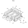
- Fig. 1 is a perspective view of the outer appearance showing the configuration of a portion of the vehicle, in the embodiment.
- an X axis, a Y axis, and a Z axis are axes orthogonal to each other.
- the X axis corresponds to a traveling direction of the vehicle.
- the traveling direction refers to a direction in which the vehicle runs forward and backward.
- the Y axis corresponds to a transverse direction of the vehicle, and the Z axis corresponds to a direction of gravity.
- the vehicle in the present embodiment is a vehicle on which a battery pack (power source apparatus) is mounted.
- Examples of the vehicle include a hybrid vehicle and an electric vehicle.
- the hybrid vehicle is a vehicle which has not only the battery pack but also another power source such as an internal combustion engine or a fuel battery which outputs energy for use in running of the vehicle.
- the electric vehicle is a vehicle which runs only with the output from the battery pack.
- the battery pack in the present embodiment is discharged to output energy for use in running of the vehicle or is charged with energy produced in braking of the vehicle or with power supplied from the outside of the vehicle.
- a vehicle body 1 has a pair of side members 10 extending in the X direction, a cross member 12 extending in the Y direction and connected to the pair of side members 10, and a floor panel 11 fixed to the pair of side members 10.
- the side members 10 and the cross member 12 constitute the skeleton of the vehicle body 1.
- the floor panel 11 has a housing portion 11a formed therein for housing a spare tire.
- the housing portion 11a can be omitted.
- a protecting frame (protecting structure) 20 is placed above the housing portion 11a of the floor panel 11.
- the protecting frame 20 is provided for protecting the battery pack mounted on the vehicle.
- the protecting frame 20 has a structure which the periphery of the battery pack to prevent the direct action of an external force on the battery pack.
- the protecting frame 20 is placed in a rearward position of the vehicle body 1.
- the protecting frame 20 battery pack
- the protecting frame 20 can be placed in a luggage room of the vehicle.
- the battery pack 30 has an assembled battery 31 and a case 32 for housing the assembled battery 31.
- the assembled battery 31 is fixed to the case 32 by fastening members such as bolts, and the case 32 is fixed to the protecting frame 20 through fastening members such as bolts.
- the assembled battery 31 is formed of a plurality of cells connected electrically in series through a bus bar.
- a secondary battery such as a nickel metal hydride battery or a lithium-ion battery can be used as the cell.
- an electric double layer capacitor (capacitor) can be used.
- the cell may have any shape, and for example, a cylindrical type or a square type can be used. It is possible to supply a gas for adjusting the temperature of the assembled battery 31 into the case 32. Specifically, a gas for cooling can be supplied to suppress a rise in temperature of the assembled battery 31. In addition, a gas for heating can be supplied to suppress a drop in temperature of the assembled battery 31.
- a fluid can be housed in the case 32 instead of the gas.
- an insulating fluid can be housed to promote heat transfer between the assembled battery 31 and the case 32.
- an insulating fluid an insulating oil or a fluorochemical inert fluid can be used.
- the protecting frame 20 is fixed to the side members 10 and the floor panel 11 through a plurality of fixing members 13, 14, and 15.
- a pair of first fixing members 13 is connected to the portion of the protecting frame 20 that is located in a rearward position of the vehicle.
- the first fixing members 13 are fixed to the associated side members 10 by fastening members such as bolts.
- a pair of second fixing members 14 and a pair of third fixing members 15 are connected to the portions of the protecting frame 20 that are located in a forward position of the vehicle.
- the second fixing members 14 are fixed to the associated side members 10 by fastening members such as bolts.
- the third fixing members 15 are located between the pair of second fixing members 14 in the Y direction and are fixed to the floor panel 11 by fastening members such as bolts.
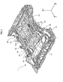
- Fig. 3 is a perspective view showing the outer appearance of the protecting frame 20.
- Fig. 4 is a diagram illustrating the protecting frame 20 viewed from the top (Z direction) and showing the configuration of a portion of the protecting frame 20.
- a first frame 21a is located on a rearward side of the vehicle and extends in the Y direction.
- a second frame 21b is located in the direction of gravity (downward direction) relative to the first frame 21a and extends in the Y direction.
- the first frame 21a and the second frame 21b are placed generally in parallel within a Y-Z plane.
- the lengths of the first frame 21a and the second frame 21b in the Y direction are larger than the length of the battery pack 30 in the Y direction.
- the first fixing members 13 are connected to both ends of the second frame 21b.
- third frames 21c extending in the Z direction are connected to the first frame 21a and the second frame 21b.
- the third frame 21c has a length larger than that of the battery pack 30 in then direction.
- the four third frames 21c are placed at equal intervals in the Y direction. While the four third frames 21c are provided in the present embodiment, the present invention is not limited thereto.
- the number of the third frames 21c and the interval between the third frames 21c canbe set as appropriate. Specifically, the number and the like of the third frames 21c can be set in view of the strength and the like of the protecting frame 20.
- a fourth frame 21d is located in a forward position of the vehicle and extends in the Y direction. In contrast to the other fames, the fourth frame 21d has a triangular shape in section orthogonal to a longitudinal direction of the fourth frame 21d.
- a fifth frame 21e is located in the direction of gravity (downward direction) relative to the fourth frame 21d and extends in the Y direction.
- the second fixing members 14 are connected to both ends of the fifth frame 21e.
- the third fixing members 15 are connected to central portions of the fifth frame 21e.
- the lengths of the fourth frame 21d and the fifth frame 21e in the Y direction are larger than the length of the battery pack 30 in the Y direction.
- Four sixth frames 21f are connected to the fourth frame 21d and the fifth frame 21e.
- the sixth frames 21f extend in the Z direction such that they are inclined with respect to the Y-Z plane.
- the end portions of the sixth frames 21f that are connected to the fifth frames 21e are located forward of the vehicle with respect to the end portions of the sixth frames 21f that are connected to the fourth frames 21d.
- the four sixth frames 21f are placed at equal intervals in the Y direction.
- the sixth frames 21f are inclined with respect to the Y-Z plane in the embodiment, the invention is not limited thereto. Specifically, the sixth frames 21f can be placed along the Z direction similarly to the third frames 21c . While the four sixth frames 21f are provided in the present embodiment, the present invention is not limited thereto.
- the number of the sixth frames 21f and the interval between the sixth frames 21f can be set as appropriate. Specifically, the number and the like of the sixth frames 21f can be set in view of the strength and the like of the protecting frame 20.
- Seven seventh frames 21g extending in the X direction are connected to the first frame 21a and the fourth frame 21d.
- the first frame 21a, the fourth frame 21d, and the seventh frames 21g are located in the same plane (in an X-Y plane) and constitute an upper plane of the protecting frame 20.
- the number of the seventh frames 21g and the interval between the seventh frames 21g can be set as appropriate.
- Eight eighth frames 21h extending in the X direction are connected to the second frame 21b and the fifth frame 21e.
- the second frame 21b, the fifth frame 21e, and the eighth frames 21h are located in the same plane (in the X-Y plane) and constitute a lower plane of the protecting frame 20.
- the interval between the upper plane and the lower plane of the protecting frame 20 is larger than the length of the battery pack 30 in the Z direction.
- the lengths of the eighth frames 21h and the seventh frames 21g in the X direction are larger than the length of the battery pack 30 in the X direction.
- the number of the eighth frames 21h and the interval between the eighth frames 21h can be set as appropriate.
- Abutting frames (abutting members) 22 extending toward the cross member 12 are connected to both ends of the second frame 21b.
- the abutting frames 22 and the four eighth frames 21h are located in the same plane (in the X-Y plane), and the abutting frames 22 are placed such that they are inclined with respect to eighty frames 21h.
- the abutting frames 22 places in a rearward position of vehicle, relative to the cross member 12, and a portion of the cross member 12 and the abutting frames 22 are located in the same plane (in the X-Y plane).
- An area of each of the abutting frames 22 closer to its end is connected to the eighth frame 21h through a support frame 23.
- the support frame 23 is provided for supporting the area of the abutting frame 22 closer to the end.
- the support frame 23 can be omitted.
- Protruding portions 12a protruding in the Z direction are formed at both end portions of the cross members 12.
- the protruding portion 12a has a surface opposed to an end portion 22a of the abutting frame 22.
- a predetermined clearance is provided between the protruding portion 12a and the end portion 22a of the abutting frame 22 .
- the clearance is provided for preventing interference between the end portion 22a of the abutting frame 22 and the protruding portion 12a of the cross member 12 in mounting the protecting frame 20 on the vehicle body 1. If the accuracy of mounting of the protecting frame 20 on the vehicle body 1 can be ensured, the end portion 22a of the abutting frame 22 can be in contact with the protruding portion 12a of the cross member 12.
- the frames 21a to 21h, 22, and 23 constituting the protecting frame 20 canbe connected to each other by welding or canbe connected by using fastening members such as bolts.
- Fig. 5 is a side view showing the configuration of the protecting frame 20.
- an excessive load (external force) is applied to a rearward portion of the vehicle in a collision or the like of the vehicle, the portion of the floor panel 11 that is located in a rearward position of the vehicle is deformed. Such deformation of the floor panel 11 can absorb the external force.
- the external force is also applied to the protecting frame 20 depending on the degree of the deformation of the floor panel 11.
- an arrow represents the external force F acting on the protecting frame 20.
- the protecting frame 20 is displaced in the direction in which the external force F acts, so that the end portion 22a of the abutting frame 22 abuts on the protruding portion 12a of the cross member 12.
- This causes the external force F acting on the protecting frame 20 to be transferred to the cross member 12 through the abutting frame 22. Since the cross member 12 is subjected to the external force F through the abutting frame 22, the cross member 12 is deformed to absorb the external force F.
- the cross member 12 is a member constituting part of the skeleton of the vehicle body 1, and thus the external force F transferred to the cross member 12 through the abutting frame 22 is converted into force which will run the vehicle forward.
- the forward running of the vehicle can absorb the external force F.
- the connecting portion between the protecting frame 20 and the vehicle body 1 can have a robust structure in order to prevent detachment of the protecting frame 20 from the vehicle body 1 due to the external force F acting on the protecting frame 20. In this case, however, the number of parts used in the connecting portion is increased.
- a configuration in which the protecting frame 20 and the vehicle body 1 are merely fixed mechanically to each other has a limit to the external force F, and protesting frame 20 may be detached from vehicle, body 1 depending on the magnitude of the external force F.
- the direct action of the external force on the battery pack 30 can be suppressed even when the vehicle is subjected to a shock. Specifically, the external force reaches the protecting frame 20 before it reaches the battery pack 30, so that the application of an excessive load to the battery pack 30 can be prevented.
- the battery pack 30 can be reinforced to ensure the strength of the battery pack 30.
- the use of the conf iguration of the protecting frame 20 in the present embodiment can result in a simpler configuration. Specifically, if the battery pack 30 is reinforced, a complicated reinforcement structure shouldbe used, but the protecting frame 20 in the present embodiment can be realized with a simpler structure since it is provided by simply combining the plurality of frames.
- the external force F acting on the protecting frame 20 is transferred to the cross member 12 through the abutting frame 22 to absorb the external force F as described above.
- This can achieve the simple structure for fixing the protecting frame 20 to the vehicle body 1 to prevent an increase in cost of the fixing structure of the protecting frame 20 to the vehicle body 1.
- the end portion 22a of the abutting frame 22 abuts on the cross member 12 before the first fixing member 13 is detached from the side members 10.
- the external force F can be conveyed to the cross member 12 in a relatively early stage after the external force F acts on the protecting frame 20, thereby allowing a reduction in load on the protecting frame 20.
- the present embodiment can readily provide the abovementioned effects when the battery pack 30 is increased in size. Specifically, when the battery pack 30 is increased in size, the protecting frame 20 is located close to a rearward portion of the vehicle. The battery pack 30 is increased in size when a plurality of assembled batteries 31 are used or when the number of cells constituting the assembled battery 31 is increased.
- the protecting frame 2 0 in the present embodiment can be used to convey the external force applied to the protecting frame 20 efficiently to the cross member 12 through the abutting frame 22.
- the present invention is not limited thereto. Specifically, when the end portion 22a of the abutting frame 22 is caused to abut on a member which constitutes part of the skeleton of the vehicle body 1, the same effects as those in the present embodiment can be provided.
- the member which constitutes part of the skeleton of the vehicle body 1 include not only the cross member 12 but also a reinforcement member (gusset) serving as a reinforcement in connecting the frames of the vehicle, for example.
- the present invention is not limited thereto.
- the abutting frames 22 can be connected to the third frames 21c.
- the external force F applied to the protecting frame 20 can also be transferred to the cross member 12 through the abutting frames 22.
- the abutting frames 22 should extend toward the protruding portions 12a of the cross member 12, and the specific shape of the abutting frames 22 can be set as appropriate.
- each of the abutting frames 22 has a hollow shape in the present embodiment, another shape can be used.
- FIG. 6 is a side view showing the configuration of a protecting frame in the present embodiment.
- members having the same functions as those described in Embodiment 1 are designated with the same reference numerals, and detailed description thereof is omitted. In the following, different points from those in Embodiment 1 will be described.
- the protecting frame 20 of Embodiment 1 has the abutting frames 22 which abut on the cross member 12, the abutting frames 22 and the support frames 23 are not provided in the present embodiment.
- a connecting member 24 extending along a first frame 21a is fixed to a side face of the first frame 21a.
- a seventh frame 21g is fixed to the first frame 21a by welding.
- a connecting member 25 which is to be connected to the connecting member 24 is fixed to an end of each of third frames 21c.
- the connecting members 24 and 25 are connected to each other by fastening members such as bolts to fix the first frame 21a to the third frame 21c.
- Fig. 6 the state before the first frame 21a is fixed to the third frame 21c.
- the first frame 21a is moved in a direction indicated by an arrow A.
- the third frame 21c is formed integrally with an eighth frame 21h.
- the third frame 21c and the eighth frame 21h can be formed integrally by molding, or the third frame 21c and the eighth frame 21h can be formed integrally by welding.
- the third frame 21c of the present embodiment is different from the third frame 21c described in Embodiment 1. Specifically, while the third frame 21c is connected to the second frame 21b extending in the Y direction in Embodiment 1, the third frame 21c is connected to the eighth frame 21h in the present embodiment.
- a fixing member 13 is provided in a corner portion of the frame in which the third frame 21c and the eighth frame 21h are formed integrally.
- the plurality of third frames 21c are placed in a Y direction in the present embodiment, and a frame is provided between the adjacent ones of the third frames 21c in the Y direction for connection of the third frames 21c.
- the frame extends in the Y direction similarly to the second frame 21b described in Embodiment 1.
- the deformation of the third frame 21c can be suppressed even when an external force F is applied to the protecting frame 20.
- the protecting frame 20 has the configuration shown in Fig. 7 .
- the third frame 21c is deformed and applies an excessive load to a battery pack 30 when the protecting frame 20 is subjected to an external force F.
- the configuration shown in Fig. 7 will be described specifically.
- one end of the third frame 21c is fixed to the first frame 21a, and a connecting member 26 is provided at the other end of the third frame 21c.
- a connecting member 27 which is to be connected to the connecting member 26 is provided for the second frame 21b.
- the connecting members 26 and 27 have flange portions 26a and 27a opposite to each other in a Z direction, respectively.
- flange portions 26a and 27a are connected to each other by fastening members such as bolts to fix the third frame 21c to the second frame 21b.
- Fig. 7 shows the state before the third frame 21c is fixed to the second frame 21b.
- the third fame 21c is moved in a direction indicated by an arrow A.
- the third frame 21c may be deformed as shown by dotted lines in Fig. 7 when the external force F is applied.
- the end portion of the third frame 21c applies an excessive load to the battery pack 30. Since the third frame 21c and the second frame 21b are fixed to each other only by the connection of the connecting members 26 and 27, the third frame 21c is easily detached from the second frame 21b unless the connecting portion of the connecting members 26 and 27 has greater rigidity.
- the third frame 21c and the eighth frame 21h are formed integrally, and the end portion of the third frame 21c is placed adjacent to the side face of the first frame 21a with the connecting member 24 interposed between them.
- the deformation of the end portion of the third frame 21c as shown by the dotted lines in Fig. 7 can be prevented. This can improve the strength of the protecting frame 20 against shocks from the rear of the vehicle.
- the abutting frames 22 and the support frames 23 described in Embodiment 1 are not provided in the present embodiment, the abutting frames 22 and the support frames 23 can be provided similarly to Embodiment 1. This efficiently suppress the application of an excessive load to the battery pack 30.
- Fig. 8 is a side view showing the configuration of a protecting frame in the present embodiment.
- the configuration of the protecting frame is changed from that in Embodiment 1.
- Members having the same functions as those described in Embodiment 1 are designated with the same reference numerals.
- the protecting frame 20 in Embodiment 1 has the abutting frames 22 which abut on the cross member 12, the abutting frames 22 and the support frames 23 are not provided in the present embodiment.
- a third frame 21c is fixed to a side face of a first frame 21a by welding or the like.
- a connecting member 26 is attached to an end portion of the third frame 21c and a depression portion 21c1 is formed in the end portion.
- a connecting member 27 is attached to a side face of a second frame 21b.
- the connecting member 27 is connected to the connecting member 26 by fastening members such as bolts.
- fastening members such as bolts.
- flange portions 26a and 27a provided for the connecting members 26 and 27, respectively, are connected to each other by fastening such as bolts to fix the third frame 21c to the second frame 21b.
- a projection portion 21b1 which is to be inserted into the depression portion 21c1 of the third frame 21c is formed integrally with the side face of the second frame 21b that is opposed to the end portion of the third frame 21c.
- the third frame 21c is moved toward the second frame 21b in a direction indicated by an arrow A to insert the projection portion 21b1 into the depression portion 21c1 of the third frame 21c and the connecting members 26 and 27 are fixed by fastening members to constitute the protecting frame 20.
- the strength of the protecting frame 20 is ensured by the engagement of the projection portion 21b1 and the depression portion 21c1 and the connection of the connecting members 26 and 27.
- the strength of the protecting frame 20 can be improved as compared with the configuration shown in Fig. 7 . Even when the protecting frame 20 is subjected to an external force F, the deformation of the third frame 21c as shown by the dotted lines in Fig. 7 can be prevented.
- the abutment of the projection portion 21b1 on the depression portion 21c1 can enhance the strength in the connecting portion of the third frame 21c and the second frame 21b. This can achieve a simple configuration of the connecting members 26 and 27. Specifically, it is essential only that the connecting structure of the connecting members 26 and 27 should be formed such that the projection portion 21b1 is not be detached from the depression portion 21c1.
- the present embodiment has the configuration in which the proj ectionportion 21b1 is inserted into the depression portion 21c1, the present invention is not limited thereto.
- the projection portion 21b1 can be in contact with the side face of the third frame 21c that is opposed to the battery pack 30. In this case, the position of the projection portion 21b1 is different from that in the configuration shown in Fig. 8 .
- the abutment of the side face of the third frame 21c on protection portion 21b1 can also suppress the deformation of the end portion of the third frame 21c.
- the abutting frames 22 and the support frames 23 described in Embodiment 1 are not provided in the present embodiment, the abutting frames 22 and the support frames 23 can be provided similarly to Embodiment 1. This can efficiently suppress the application of an excessive load to the battery pack 30.
- the present invention is not limited thereto. Specifically, a projection portion corresponding to the projection portion 21b1 can be provided for the third frame 21c, and a depression portion corresponding to the depression portion 21c1 can be provided for the second frame 21b.
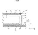
- Fig. 9 is a side view showing the configuration of a protecting frame in the present embodiment.
- members having the same functions as those described in Embodiments 1 and 2 are designated with the same reference numerals, and detailed description thereof is omitted. In the following, different points from those in Embodiments 1 and 2 will be described.
- the protecting frame 20 in Embodiment 1 has the abutting frames 22 which abut on the cross member 12, the abutting frames 22 and the support frames 23 are not provided in the present embodiment.
- the protecting frame 20 in Embodiment 1 has the third frames 21c provided on the upper surface of the second frame 21b, a side face of a third frame 21c is connected to a side face of a second frame 21b in the present embodiment.
- a fixing member 13 is provided for an end portion of the third frame 21c.
- the deformation of end portion of the third frame 21c can be suppressed even when an external force F is applied.
- One end portion of the third frame 21c is connected to a first frame 21a extending in a Y direction, while the other end portion of the third frame 21c is connected to the second frame 21b extending in the Y direction.
- both end portions of the third frame 21c are prevented from being deformed by the first frame 21a and the second frame 21b. This can enhance the strength of the protecting frame 20.
- the abutting frames 22 and the support frames 23 described in Embodiment 1 are not provided in the present embodiment, the abutting frames 22 and the support frames 23 can be provided similarly to Embodiment 1. This can efficiently suppress the application of an excessive load to the battery pack 30.
Landscapes
- Engineering & Computer Science (AREA)
- Transportation (AREA)
- Mechanical Engineering (AREA)
- Life Sciences & Earth Sciences (AREA)
- Sustainable Development (AREA)
- Sustainable Energy (AREA)
- Power Engineering (AREA)
- Chemical & Material Sciences (AREA)
- Combustion & Propulsion (AREA)
- Arrangement Or Mounting Of Propulsion Units For Vehicles (AREA)
- Body Structure For Vehicles (AREA)
- Battery Mounting, Suspending (AREA)
Abstract
Description
- The present invention relates to a protecting structure in which a power source apparatus mounted on a vehicle is surrounded by a plurality of frames to protect the power source apparatus against shocks from the outside.
- Secondary batteries have conventionally been mounted on vehicles such that the output from the secondary battery is used to run the vehicle or the secondary battery is charged with regenerative energy from the vehicle (for example, see Patent Documents 1 and 2) . In such a vehicle, it is necessary to suppress the application of an excessive load to the secondary battery to prevent damage to the secondary battery when the vehicle is subjected to an external force in a collision.
- To address this, in Patent Document 1, a floor panel is formed to be easy-to-deform to absorb shocks so that no external force may act on a battery. In Patent Document 2, a bracket connected to a battery pack has a rotatable configuration and the bracket is rotated to absorb a shock when a vehicle is subj ected to the shock.
- Patent Document 1: Japanese Patent Laid-Open No.
2001-113959
Patent Document 2: Japanese Patent Laid-open No.2007-253933 Figs. 1 ,7 , and8 ) - Patent Document 1, however, discloses the configuration in which the battery is merely fixed to the floor panel. An external force may act on the battery depending on the magnitude of the external force applied to a vehicle. On the other hand, Patent Document 2 discloses the configuration in which the battery pack is fixed to a floor panel by using bolts. An external force may act on the battery pack depending on the magnitude of the external force applied to the vehicle.
- It is thus an object of the present invention to provide a protecting structure for a power source apparatus capable of suppressing the action of an external force on the power source apparatus when a vehicle is subjected to a shock.
- According to the present invention, a protecting structure for a power source apparatus comprises a frame unit in which a plurality of frames are connected to each other and surround the power source apparatus mounted on a vehicle; and an abutting member connected to the frame unit and extending in a direction in which the abutting member abuts on a vehicle body.
- Herein the abutting member can be arranged so as to extend in a direction in which an external force in a predetermined direction acts on the vehicle. In addition, the abutting member is caused to abut on the vehicle body in response to displacement of the frame unit due to an external force. The structure in which the abutting member is abutting on the vehicle body can be used.
- The frame unit can be fixed to the vehicle body through a fixing members. According to the protecting structure of the invention, it is possible to absorb an external force by abutting the abutting member on the vehicle body. Therefore it is not necessary to fixing of fixing members. Specifically, the structure of fixing member can be simplified.
- The power source apparatus can be placed in a rearward position of the vehicle . In addition, the power source apparatus can be formed of a secondary battery. Specifically, the power source apparatus comprises an assembled battery having a plurality of cells (secondary battery) and a case housing the assembled battery. The vehicle body on which the abutting member abuts is a cross member extending in a direction from left to right of the vehicle.
- According to another aspect, the present invention provides a frame unit in which a plurality of frames are connected to each other and surround a power source apparatus mounted on a vehicle, wherein, of the plurality of frames, a frame placed along a lower surface of the power source apparatus is formed integrally with a frame placed along a side face of the power source apparatus.
- According to another aspect, the present inventionprovides a frame unit in which a plurality of frames are connected to each other and surround a power source apparatus mounted on a vehicle, wherein the plurality of frames include two frames placed along side faces of the power source apparatus and extending in direct ions orthogonal to each other. One of the two frames has a projection portion which abuts on the other frame to prevent deformation of the frame.
- According to the present invention, the frame unit formed of the plurality of frames is used to surround the sower source apparatus, so that when an external force is applied to the vehicle, the direct action of the external force on the source apparatus can be suppressed. In addition, since the abutting member extending in the direction in which the abutting member abuts on the vehicle body is connected to the frame unit, the external force applied to the frame unit can be conveyed to the vehicle body through the abutting member. This can suppress the action of the external force on the power source apparatus through the frame unit.
-
- [
Fig. 1 ] A perspective view of the outer appearance showing the configuration of a portion of a vehicle in Embodiment 1 of the present invention. - [
Fig. 2 ] A schematic diagram showing the configuration of a battery pack. - [
Fig. 3 ] A perspective view of the outer appearance showing the configuration of a protecting frame in Embodiment 1. - [
Fig. 4 ] A top view showing the configuration of a portion of the protecting frame in Embodiment 1. - [
Fig. 5 ] A side view showing the configuration of the protecting frame in Embodiment 1. - [
Fig. 6 ] A side view showing the configuration of a protecting frame in Embodiment 2 of the present invention. - [
Fig. 7 ] A side view showing the configuration of a protecting frame in a comparative example of Embodiment 2. - [
Fig. 8 ] A side view showing the configuration of a protecting frame in Embodiment 3 of the present invention. - [
Fig. 9 ] A side view showing the configuration of a protecting frame in Embodiment 4 of the present invention. - Preferred embodiments of the present invention will hereinafter be described.
- A vehicle in Embodiment 1 of the present invention will be described with reference to
Fig. 1. Fig. 1 is a perspective view of the outer appearance showing the configuration of a portion of the vehicle, in the embodiment. InFig. 1 , an X axis, a Y axis, and a Z axis are axes orthogonal to each other. The X axis corresponds to a traveling direction of the vehicle. The traveling direction refers to a direction in which the vehicle runs forward and backward. The Y axis corresponds to a transverse direction of the vehicle, and the Z axis corresponds to a direction of gravity. - The vehicle in the present embodiment is a vehicle on which a battery pack (power source apparatus) is mounted. Examples of the vehicle include a hybrid vehicle and an electric vehicle. The hybrid vehicle is a vehicle which has not only the battery pack but also another power source such as an internal combustion engine or a fuel battery which outputs energy for use in running of the vehicle. The electric vehicle is a vehicle which runs only with the output from the battery pack. The battery pack in the present embodiment is discharged to output energy for use in running of the vehicle or is charged with energy produced in braking of the vehicle or with power supplied from the outside of the vehicle.
- A vehicle body 1 has a pair of
side members 10 extending in the X direction, across member 12 extending in the Y direction and connected to the pair ofside members 10, and afloor panel 11 fixed to the pair ofside members 10. Theside members 10 and thecross member 12 constitute the skeleton of the vehicle body 1. - The
floor panel 11 has ahousing portion 11a formed therein for housing a spare tire. Thehousing portion 11a can be omitted. A protecting frame (protecting structure) 20 is placed above thehousing portion 11a of thefloor panel 11. The protectingframe 20 is provided for protecting the battery pack mounted on the vehicle. Specifically, the protectingframe 20 has a structure which the periphery of the battery pack to prevent the direct action of an external force on the battery pack. - The specific configuration of the protecting
frame 20 will be described later. As shown inFig. 1 , the protectingframe 20 is placed in a rearward position of the vehicle body 1. For example, the protecting frame 20 (battery pack) can be placed in a luggage room of the vehicle. - As shown in
Fig. 2 , thebattery pack 30 has an assembledbattery 31 and acase 32 for housing the assembledbattery 31. The assembledbattery 31 is fixed to thecase 32 by fastening members such as bolts, and thecase 32 is fixed to the protectingframe 20 through fastening members such as bolts. The assembledbattery 31 is formed of a plurality of cells connected electrically in series through a bus bar. A secondary battery such as a nickel metal hydride battery or a lithium-ion battery can be used as the cell. Instead of the secondary battery, an electric double layer capacitor (capacitor) can be used. - The cell may have any shape, and for example, a cylindrical type or a square type can be used. It is possible to supply a gas for adjusting the temperature of the assembled
battery 31 into thecase 32. Specifically, a gas for cooling can be supplied to suppress a rise in temperature of the assembledbattery 31. In addition, a gas for heating can be supplied to suppress a drop in temperature of the assembledbattery 31. A fluid can be housed in thecase 32 instead of the gas. Specifically, an insulating fluid can be housed to promote heat transfer between the assembledbattery 31 and thecase 32. As the insulating fluid, an insulating oil or a fluorochemical inert fluid can be used. - As in
Fig. 1 , the protectingframe 20 is fixed to theside members 10 and thefloor panel 11 through a plurality of fixingmembers - A pair of first fixing
members 13 is connected to the portion of the protectingframe 20 that is located in a rearward position of the vehicle. Thefirst fixing members 13 are fixed to the associatedside members 10 by fastening members such as bolts. A pair ofsecond fixing members 14 and a pair ofthird fixing members 15 are connected to the portions of the protectingframe 20 that are located in a forward position of the vehicle. Thesecond fixing members 14 are fixed to the associatedside members 10 by fastening members such as bolts. Thethird fixing members 15 are located between the pair ofsecond fixing members 14 in the Y direction and are fixed to thefloor panel 11 by fastening members such as bolts. - Next, the configuration of the protecting
member 20 will be described with reference toFigs. 3 and4 .Fig. 3 is a perspective view showing the outer appearance of the protectingframe 20.Fig. 4 is a diagram illustrating the protectingframe 20 viewed from the top (Z direction) and showing the configuration of a portion of the protectingframe 20. - A
first frame 21a is located on a rearward side of the vehicle and extends in the Y direction. Asecond frame 21b is located in the direction of gravity (downward direction) relative to thefirst frame 21a and extends in the Y direction. Thefirst frame 21a and thesecond frame 21b are placed generally in parallel within a Y-Z plane. The lengths of thefirst frame 21a and thesecond frame 21b in the Y direction are larger than the length of thebattery pack 30 in the Y direction. Thefirst fixing members 13 are connected to both ends of thesecond frame 21b. - Four
third frames 21c extending in the Z direction are connected to thefirst frame 21a and thesecond frame 21b. Thethird frame 21c has a length larger than that of thebattery pack 30 in then direction. The fourthird frames 21c are placed at equal intervals in the Y direction. While the fourthird frames 21c are provided in the present embodiment, the present invention is not limited thereto. The number of thethird frames 21c and the interval between thethird frames 21c canbe set as appropriate. Specifically, the number and the like of thethird frames 21c can be set in view of the strength and the like of the protectingframe 20. - A
fourth frame 21d is located in a forward position of the vehicle and extends in the Y direction. In contrast to the other fames, thefourth frame 21d has a triangular shape in section orthogonal to a longitudinal direction of thefourth frame 21d. Afifth frame 21e is located in the direction of gravity (downward direction) relative to thefourth frame 21d and extends in the Y direction. Thesecond fixing members 14 are connected to both ends of thefifth frame 21e. Thethird fixing members 15 are connected to central portions of thefifth frame 21e. - The lengths of the
fourth frame 21d and thefifth frame 21e in the Y direction are larger than the length of thebattery pack 30 in the Y direction. Foursixth frames 21f are connected to thefourth frame 21d and thefifth frame 21e. Thesixth frames 21f extend in the Z direction such that they are inclined with respect to the Y-Z plane. Specifically, the end portions of thesixth frames 21f that are connected to thefifth frames 21e are located forward of the vehicle with respect to the end portions of thesixth frames 21f that are connected to thefourth frames 21d. The foursixth frames 21f are placed at equal intervals in the Y direction. - While the
sixth frames 21f are inclined with respect to the Y-Z plane in the embodiment, the invention is not limited thereto. Specifically, thesixth frames 21f can be placed along the Z direction similarly to thethird frames 21c . While the foursixth frames 21f are provided in the present embodiment, the present invention is not limited thereto. The number of thesixth frames 21f and the interval between thesixth frames 21f can be set as appropriate. Specifically, the number and the like of thesixth frames 21f can be set in view of the strength and the like of the protectingframe 20. - Five
seventh frames 21g extending in the X direction are connected to thefirst frame 21a and thefourth frame 21d. Thefirst frame 21a, thefourth frame 21d, and theseventh frames 21g are located in the same plane (in an X-Y plane) and constitute an upper plane of the protectingframe 20. The number of theseventh frames 21g and the interval between theseventh frames 21g can be set as appropriate. - Four
eighth frames 21h extending in the X direction are connected to thesecond frame 21b and thefifth frame 21e. Thesecond frame 21b, thefifth frame 21e, and theeighth frames 21h are located in the same plane (in the X-Y plane) and constitute a lower plane of the protectingframe 20. The interval between the upper plane and the lower plane of the protectingframe 20 is larger than the length of thebattery pack 30 in the Z direction. The lengths of theeighth frames 21h and theseventh frames 21g in the X direction are larger than the length of thebattery pack 30 in the X direction. The number of theeighth frames 21h and the interval between theeighth frames 21h can be set as appropriate. - Abutting frames (abutting members) 22 extending toward the
cross member 12 are connected to both ends of thesecond frame 21b. The abutting frames 22 and the foureighth frames 21h are located in the same plane (in the X-Y plane), and the abutting frames 22 are placed such that they are inclined with respect to eightyframes 21h. As shown inFig. 4 , the abutting frames 22 places in a rearward position of vehicle, relative to thecross member 12, and a portion of thecross member 12 and the abutting frames 22 are located in the same plane (in the X-Y plane). - An area of each of the abutting frames 22 closer to its end is connected to the
eighth frame 21h through asupport frame 23. Thesupport frame 23 is provided for supporting the area of the abuttingframe 22 closer to the end. Thesupport frame 23 can be omitted. - Protruding
portions 12a protruding in the Z direction are formed at both end portions of thecross members 12. The protrudingportion 12a has a surface opposed to anend portion 22a of the abuttingframe 22. A predetermined clearance is provided between the protrudingportion 12a and theend portion 22a of the abuttingframe 22 . The clearance is provided for preventing interference between theend portion 22a of the abuttingframe 22 and the protrudingportion 12a of thecross member 12 in mounting the protectingframe 20 on the vehicle body 1. If the accuracy of mounting of the protectingframe 20 on the vehicle body 1 can be ensured, theend portion 22a of the abuttingframe 22 can be in contact with the protrudingportion 12a of thecross member 12. - The
frames 21a to 21h, 22, and 23 constituting the protectingframe 20 canbe connected to each other by welding or canbe connected by using fastening members such as bolts. - Next, the functions of the protecting
frame 20 of the present embodiment will be described with reference toFig. 5. Fig. 5 is a side view showing the configuration of the protectingframe 20. - When an excessive load (external force) is applied to a rearward portion of the vehicle in a collision or the like of the vehicle, the portion of the
floor panel 11 that is located in a rearward position of the vehicle is deformed. Such deformation of thefloor panel 11 can absorb the external force. The external force is also applied to the protectingframe 20 depending on the degree of the deformation of thefloor panel 11. InFig. 5 , an arrow represents the external force F acting on the protectingframe 20. - For example, when the external force F exceeds the yield point of the
first fixing members 13, the protectingframe 20 is displaced in the direction in which the external force F acts, so that theend portion 22a of the abuttingframe 22 abuts on the protrudingportion 12a of thecross member 12. This causes the external force F acting on the protectingframe 20 to be transferred to thecross member 12 through the abuttingframe 22. Since thecross member 12 is subjected to the external force F through the abuttingframe 22, thecross member 12 is deformed to absorb the external force F. - The
cross member 12 is a member constituting part of the skeleton of the vehicle body 1, and thus the external force F transferred to thecross member 12 through the abuttingframe 22 is converted into force which will run the vehicle forward. The forward running of the vehicle can absorb the external force F. - It is contemplated that the connecting portion between the protecting
frame 20 and the vehicle body 1 can have a robust structure in order to prevent detachment of the protectingframe 20 from the vehicle body 1 due to the external force F acting on the protectingframe 20. In this case, however, the number of parts used in the connecting portion is increased. A configuration in which the protectingframe 20 and the vehicle body 1 are merely fixed mechanically to each other has a limit to the external force F, and protestingframe 20 may be detached from vehicle, body 1 depending on the magnitude of the external force F. - Since the
battery pack 30 is surrounded by the protectingframe 20 in the present embodiment, the direct action of the external force on thebattery pack 30 can be suppressed even when the vehicle is subjected to a shock. Specifically, the external force reaches the protectingframe 20 before it reaches thebattery pack 30, so that the application of an excessive load to thebattery pack 30 can be prevented. - Alternatively, the
battery pack 30 can be reinforced to ensure the strength of thebattery pack 30. The use of the conf iguration of the protectingframe 20 in the present embodiment, however, can result in a simpler configuration. Specifically, if thebattery pack 30 is reinforced, a complicated reinforcement structure shouldbe used, but the protectingframe 20 in the present embodiment can be realized with a simpler structure since it is provided by simply combining the plurality of frames. - In the present embodiment, the external force F acting on the protecting
frame 20 is transferred to thecross member 12 through the abuttingframe 22 to absorb the external force F as described above. This can achieve the simple structure for fixing the protectingframe 20 to the vehicle body 1 to prevent an increase in cost of the fixing structure of the protectingframe 20 to the vehicle body 1. - In the present embodiment, when the external force F acts on the protecting
frame 20, theend portion 22a of the abuttingframe 22 abuts on thecross member 12 before the first fixingmember 13 is detached from theside members 10. Thus, the external force F can be conveyed to thecross member 12 in a relatively early stage after the external force F acts on the protectingframe 20, thereby allowing a reduction in load on the protectingframe 20. - The present embodiment can readily provide the abovementioned effects when the
battery pack 30 is increased in size. Specifically, when thebattery pack 30 is increased in size, the protectingframe 20 is located close to a rearward portion of the vehicle. Thebattery pack 30 is increased in size when a plurality of assembledbatteries 31 are used or when the number of cells constituting the assembledbattery 31 is increased. - In such a case, the external force applied to the vehicle tends to act on the protecting
frame 20. Thus, the protecting frame 2 0 in the present embodiment can be used to convey the external force applied to the protectingframe 20 efficiently to thecross member 12 through the abuttingframe 22. - While the
end portion 22a of the abuttingframe 22 is caused to abut on thecross member 12 in the present embodiment, the present invention is not limited thereto. Specifically, when theend portion 22a of the abuttingframe 22 is caused to abut on a member which constitutes part of the skeleton of the vehicle body 1, the same effects as those in the present embodiment can be provided. Examples of the member which constitutes part of the skeleton of the vehicle body 1 include not only thecross member 12 but also a reinforcement member (gusset) serving as a reinforcement in connecting the frames of the vehicle, for example. - While the abutting frames 22 are connected to the
second frame 21b in the present embodiment, the present invention is not limited thereto. For example, the abutting frames 22 can be connected to thethird frames 21c. In this case, the external force F applied to the protectingframe 20 can also be transferred to thecross member 12 through the abutting frames 22. In addition, it is essential only that the abutting frames 22 should extend toward the protrudingportions 12a of thecross member 12, and the specific shape of the abutting frames 22 can be set as appropriate. Specifically, while each of the abutting frames 22 has a hollow shape in the present embodiment, another shape can be used. - A vehicle in Embodiment 2 of the present invention will be described with reference to
Fig. 6. Fig. 6 is a side view showing the configuration of a protecting frame in the present embodiment. In the present embodiment, members having the same functions as those described in Embodiment 1 are designated with the same reference numerals, and detailed description thereof is omitted. In the following, different points from those in Embodiment 1 will be described. - While the protecting
frame 20 of Embodiment 1 has the abutting frames 22 which abut on thecross member 12, the abutting frames 22 and the support frames 23 are not provided in the present embodiment. - In a protecting
frame 20 of the present embodiment, a connectingmember 24 extending along afirst frame 21a is fixed to a side face of thefirst frame 21a. Aseventh frame 21g is fixed to thefirst frame 21a by welding. - A connecting
member 25 which is to be connected to the connectingmember 24 is fixed to an end of each ofthird frames 21c. The connectingmembers first frame 21a to thethird frame 21c.Fig. 6 the state before thefirst frame 21a is fixed to thethird frame 21c. For fixing thefirst frame 21a to thethird frame 21c, thefirst frame 21a is moved in a direction indicated by an arrow A. - The
third frame 21c is formed integrally with aneighth frame 21h. For example, thethird frame 21c and theeighth frame 21h can be formed integrally by molding, or thethird frame 21c and theeighth frame 21h can be formed integrally by welding. Thethird frame 21c of the present embodiment is different from thethird frame 21c described in Embodiment 1. Specifically, while thethird frame 21c is connected to thesecond frame 21b extending in the Y direction in Embodiment 1, thethird frame 21c is connected to theeighth frame 21h in the present embodiment. In addition, a fixingmember 13 is provided in a corner portion of the frame in which thethird frame 21c and theeighth frame 21h are formed integrally. - The plurality of
third frames 21c are placed in a Y direction in the present embodiment, and a frame is provided between the adjacent ones of thethird frames 21c in the Y direction for connection of thethird frames 21c. The frame extends in the Y direction similarly to thesecond frame 21b described in Embodiment 1. - Since the
third frame 21c and theeighth frame 21h are formed integrally in the present embodiment, the deformation of thethird frame 21c can be suppressed even when an external force F is applied to the protectingframe 20. - It is contemplated that the protecting
frame 20 has the configuration shown inFig. 7 . In this case, however, thethird frame 21c is deformed and applies an excessive load to abattery pack 30 when the protectingframe 20 is subjected to an external force F. In the following, the configuration shown inFig. 7 will be described specifically. - In the configuration shows in
Fig. 7 , one end of thethird frame 21c is fixed to thefirst frame 21a, and a connectingmember 26 is provided at the other end of thethird frame 21c. A connectingmember 27 which is to be connected to the connectingmember 26 is provided for thesecond frame 21b. The connectingmembers flange portions - The
flange portions third frame 21c to thesecond frame 21b.Fig. 7 shows the state before thethird frame 21c is fixed to thesecond frame 21b. For fixing thethird frame 21c to thesecond frame 21b, thethird fame 21c is moved in a direction indicated by an arrow A. - In the configuration of the protecting
frame 20 shown inFig. 7 , thethird frame 21c may be deformed as shown by dotted lines inFig. 7 when the external force F is applied. When thethird frame 21c is deformed as shown by the dotted lines inFig. 7 , the end portion of thethird frame 21c applies an excessive load to thebattery pack 30. Since thethird frame 21c and thesecond frame 21b are fixed to each other only by the connection of the connectingmembers third frame 21c is easily detached from thesecond frame 21b unless the connecting portion of the connectingmembers - On the other hand, in the configuration of the present embodiment shown in
Fig. 6 , thethird frame 21c and theeighth frame 21h are formed integrally, and the end portion of thethird frame 21c is placed adjacent to the side face of thefirst frame 21a with the connectingmember 24 interposed between them. Thus, even when thethird frame 21c is subjected to the external force F, the deformation of the end portion of thethird frame 21c as shown by the dotted lines inFig. 7 can be prevented. This can improve the strength of the protectingframe 20 against shocks from the rear of the vehicle. - While the abutting frames 22 and the support frames 23 described in Embodiment 1 are not provided in the present embodiment, the abutting frames 22 and the support frames 23 can be provided similarly to Embodiment 1. This efficiently suppress the application of an excessive load to the
battery pack 30. - A vehicle in Embodiment 3 of the present invention will be described with reference to
Fig. 8. Fig. 8 is a side view showing the configuration of a protecting frame in the present embodiment. In the present embodiment, the configuration of the protecting frame is changed from that in Embodiment 1. Members having the same functions as those described in Embodiment 1 are designated with the same reference numerals. - While the protecting
frame 20 in Embodiment 1 has the abutting frames 22 which abut on thecross member 12, the abutting frames 22 and the support frames 23 are not provided in the present embodiment. - In a protecting
frame 20 of the present embodiment, athird frame 21c is fixed to a side face of afirst frame 21a by welding or the like. A connectingmember 26 is attached to an end portion of thethird frame 21c and a depression portion 21c1 is formed in the end portion. - A connecting
member 27 is attached to a side face of asecond frame 21b. The connectingmember 27 is connected to the connectingmember 26 by fastening members such as bolts. Specifically,flange portions members third frame 21c to thesecond frame 21b. - A projection portion 21b1 which is to be inserted into the depression portion 21c1 of the
third frame 21c is formed integrally with the side face of thesecond frame 21b that is opposed to the end portion of thethird frame 21c. In the present embodiment, thethird frame 21c is moved toward thesecond frame 21b in a direction indicated by an arrow A to insert the projection portion 21b1 into the depression portion 21c1 of thethird frame 21c and the connectingmembers frame 20. In the present embodiment, the strength of the protectingframe 20 is ensured by the engagement of the projection portion 21b1 and the depression portion 21c1 and the connection of the connectingmembers - In the present embodiment, the strength of the protecting
frame 20 can be improved as compared with the configuration shown inFig. 7 . Even when the protectingframe 20 is subjected to an external force F, the deformation of thethird frame 21c as shown by the dotted lines inFig. 7 can be prevented. In addition, in the present embodiment, the abutment of the projection portion 21b1 on the depression portion 21c1 can enhance the strength in the connecting portion of thethird frame 21c and thesecond frame 21b. This can achieve a simple configuration of the connectingmembers members - While the present embodiment has the configuration in which the proj ectionportion 21b1 is inserted into the depression portion 21c1, the present invention is not limited thereto. For example, the projection portion 21b1 can be in contact with the side face of the
third frame 21c that is opposed to thebattery pack 30. In this case, the position of the projection portion 21b1 is different from that in the configuration shown inFig. 8 . In this configuration, when the protectingframe 20 is subjected to the external force F, the abutment of the side face of thethird frame 21c on protection portion 21b1 can also suppress the deformation of the end portion of thethird frame 21c. - While the abutting frames 22 and the support frames 23 described in Embodiment 1 are not provided in the present embodiment, the abutting frames 22 and the support frames 23 can be provided similarly to Embodiment 1. This can efficiently suppress the application of an excessive load to the
battery pack 30. - While the depression portion 21c1 is provided for the
third frame 21c and the projection portion 21b1 is provided for thesecond frame 21b in the present embodiment, the present invention is not limited thereto. Specifically, a projection portion corresponding to the projection portion 21b1 can be provided for thethird frame 21c, and a depression portion corresponding to the depression portion 21c1 can be provided for thesecond frame 21b. - A vehicle in Embodiment 4 of the present invention will be described with reference to
Fig. 9. Fig. 9 is a side view showing the configuration of a protecting frame in the present embodiment. In the present embodiment, members having the same functions as those described in Embodiments 1 and 2 are designated with the same reference numerals, and detailed description thereof is omitted. In the following, different points from those in Embodiments 1 and 2 will be described. - While the protecting
frame 20 in Embodiment 1 has the abutting frames 22 which abut on thecross member 12, the abutting frames 22 and the support frames 23 are not provided in the present embodiment. In addition, while the protectingframe 20 in Embodiment 1 has thethird frames 21c provided on the upper surface of thesecond frame 21b, a side face of athird frame 21c is connected to a side face of asecond frame 21b in the present embodiment. A fixingmember 13 is provided for an end portion of thethird frame 21c. - In the protecting
frame 20 of the present embodiment, the deformation of end portion of thethird frame 21c can be suppressed even when an external force F is applied. One end portion of thethird frame 21c is connected to afirst frame 21a extending in a Y direction, while the other end portion of thethird frame 21c is connected to thesecond frame 21b extending in the Y direction. Thus, both end portions of thethird frame 21c are prevented from being deformed by thefirst frame 21a and thesecond frame 21b. This can enhance the strength of the protectingframe 20. - While the abutting frames 22 and the support frames 23 described in Embodiment 1 are not provided in the present embodiment, the abutting frames 22 and the support frames 23 can be provided similarly to Embodiment 1. This can efficiently suppress the application of an excessive load to the
battery pack 30.
Claims (8)
- A protecting structure for a power source apparatus, comprising:a frame unit in which a plurality of frames are connected to each other and surround the power source apparatus mounted on a vehicle; andan abutting member connected to the frame unit and extending in a direction in which the abutting member abuts on a vehicle body.
- The protecting structure for the power source apparatus according to claim 1, wherein the abutting member extends in a direction in which an external force in a predetermined direction acts on the vehicle.
- The protecting structure for the power source apparatus according to claim 1 or 2, wherein the abutting member abuts on the vehicle body in response to displacement of the frame unit due to an external force.
- The protecting structure for the power source apparatus according to claim 1 or 2, wherein the abutting member is abutting on the vehicle body.
- The protecting structure for the power source apparatus according to any one of claims 1 to 4, further comprising a fixing member for fixing the frame unit to the vehicle body.
- The protecting structure for the source apparatus according to any one of claims 1 to 5, wherein the power source apparatus is placed in a rearward position of the vehicle.
- The protecting structure for the power source apparatus according to any one of claims 1 to 6, wherein the power source apparatus is formed of a secondary battery.
- The protecting structure for the power source apparatus according to any one of claims 1 to 7, wherein the vehicle body is a cross member extending in a direction from left to right of the vehicle.
Applications Claiming Priority (2)
| Application Number | Priority Date | Filing Date | Title |
|---|---|---|---|
| JP2008129753A JP4946969B2 (en) | 2008-05-16 | 2008-05-16 | Power supply protection structure |
| PCT/JP2009/056320 WO2009139229A1 (en) | 2008-05-16 | 2009-03-27 | Power source protection structure |
Publications (3)
| Publication Number | Publication Date |
|---|---|
| EP2281707A1 true EP2281707A1 (en) | 2011-02-09 |
| EP2281707A4 EP2281707A4 (en) | 2016-12-14 |
| EP2281707B1 EP2281707B1 (en) | 2018-09-26 |
Family
ID=41318602
Family Applications (1)
| Application Number | Title | Priority Date | Filing Date |
|---|---|---|---|
| EP09746436.6A Not-in-force EP2281707B1 (en) | 2008-05-16 | 2009-03-27 | Power source protection structure |
Country Status (5)
| Country | Link |
|---|---|
| US (1) | US8540282B2 (en) |
| EP (1) | EP2281707B1 (en) |
| JP (1) | JP4946969B2 (en) |
| CN (1) | CN102015344B (en) |
| WO (1) | WO2009139229A1 (en) |
Cited By (2)
| Publication number | Priority date | Publication date | Assignee | Title |
|---|---|---|---|---|
| FR2966092A1 (en) * | 2010-10-13 | 2012-04-20 | Renault Sa | STRUCTURE FOR RECEIVING AN ELECTRIC POWER BATTERY FOR AN ELECTRIC DRIVE MOTOR OF A MOTOR VEHICLE |
| DE102011102412A1 (en) * | 2011-05-25 | 2012-11-29 | Volkswagen Aktiengesellschaft | Arrangement for traction battery in vehicle, has deformation crossbeam connected with supporting frame, where crossbeam is arranged behind supporting frame for absorbing impact forces at rear-end collision for free deformation path |
Families Citing this family (55)
| Publication number | Priority date | Publication date | Assignee | Title |
|---|---|---|---|---|
| US9288942B2 (en) | 2010-03-01 | 2016-03-22 | Yanmar Co., Ltd. | Electric riding mower having air-cooled chassis and pivotable protective cowling |
| WO2011145407A1 (en) * | 2010-05-18 | 2011-11-24 | スズキ株式会社 | Power source device protection structure |
| CN102858572B (en) * | 2010-05-19 | 2015-06-03 | 铃木株式会社 | Protective frame structure for power source device |
| JP5434860B2 (en) * | 2010-09-17 | 2014-03-05 | トヨタ車体株式会社 | Battery pack mounting structure in vehicle |
| US8875828B2 (en) | 2010-12-22 | 2014-11-04 | Tesla Motors, Inc. | Vehicle battery pack thermal barrier |
| US8702161B2 (en) | 2010-12-22 | 2014-04-22 | Tesla Motors, Inc. | System for absorbing and distributing side impact energy utilizing an integrated battery pack and side sill assembly |
| US20120161472A1 (en) | 2010-12-22 | 2012-06-28 | Tesla Motors, Inc. | System for Absorbing and Distributing Side Impact Energy Utilizing an Integrated Battery Pack |
| US8833499B2 (en) * | 2010-12-22 | 2014-09-16 | Tesla Motors, Inc. | Integration system for a vehicle battery pack |
| US9537190B2 (en) | 2011-01-06 | 2017-01-03 | Ford Global Technologies, Llc | Battery cell separators |
| US8956750B2 (en) * | 2011-01-06 | 2015-02-17 | Ford Global Technologies, Llc | Power supply structure |
| JP5519559B2 (en) * | 2011-03-10 | 2014-06-11 | トヨタ自動車株式会社 | Protection structure for in-vehicle electrical equipment |
| KR101242153B1 (en) | 2011-03-25 | 2013-03-11 | 현대로템 주식회사 | battery secession prevention Tray of railway vehicle |
| JP5729207B2 (en) * | 2011-08-09 | 2015-06-03 | マツダ株式会社 | Vehicle power supply support structure |
| WO2013054373A1 (en) * | 2011-10-11 | 2013-04-18 | トヨタ自動車株式会社 | Structure for mounting electric power storage device |
| JP5525505B2 (en) * | 2011-11-14 | 2014-06-18 | 本田技研工業株式会社 | Electric vehicle power supply device |
| JP5906689B2 (en) * | 2011-11-22 | 2016-04-20 | トヨタ自動車株式会社 | Vehicle battery mounting structure |
| US8813888B2 (en) | 2012-02-06 | 2014-08-26 | Honda Motor Co., Ltd. | Vehicle body rear structure |
| DE102012204856A1 (en) * | 2012-03-27 | 2013-10-02 | Robert Bosch Gmbh | Grounding arrangement for a vehicle |
| JP5595442B2 (en) | 2012-04-18 | 2014-09-24 | 本田技研工業株式会社 | Car power supply mounting structure |
| JP5597681B2 (en) | 2012-09-12 | 2014-10-01 | 本田技研工業株式会社 | Car body rear structure |
| US9236592B2 (en) * | 2012-11-27 | 2016-01-12 | Ford Global Technologies, Llc | Protective vehicle battery cage and method of making a battery cage |
| DE102013206508A1 (en) * | 2013-04-12 | 2014-10-16 | Robert Bosch Gmbh | Control device for an object coupling device of a vehicle, object coupling device for a vehicle and method for damping an impact of an inertia-accelerated object |
| DE102013215436A1 (en) * | 2013-08-06 | 2015-03-05 | Bayerische Motoren Werke Aktiengesellschaft | Device for receiving at least one energy module for a motor vehicle |
| CA2931864A1 (en) * | 2013-12-02 | 2015-06-11 | Honda Motor Co., Ltd. | Vehicle |
| DE102013226771A1 (en) * | 2013-12-19 | 2015-06-25 | Robert Bosch Gmbh | Method and device for mass decoupling for a motor vehicle |
| JP6063406B2 (en) * | 2014-03-06 | 2017-01-18 | 本田技研工業株式会社 | Fuel cell stack mounting structure |
| JP5979175B2 (en) * | 2014-04-21 | 2016-08-24 | トヨタ自動車株式会社 | Structure for fixing electrical equipment to vehicles |
| US9680608B2 (en) | 2014-06-27 | 2017-06-13 | Silicon Laboratories Inc. | Communication protocol with reduced overhead |
| DE102014218023A1 (en) * | 2014-09-09 | 2016-03-10 | Robert Bosch Gmbh | Grounding arrangement for a vehicle |
| US9608245B2 (en) | 2014-09-30 | 2017-03-28 | Johnson Controls Technology Company | System for providing structural integrity of a battery module |
| JP6137105B2 (en) * | 2014-09-30 | 2017-05-31 | トヨタ自動車株式会社 | Battery drive battery mounting structure |
| US9789907B2 (en) | 2015-07-27 | 2017-10-17 | Ford Global Technologies, Llc | Method and apparatus for reinforcing a vehicle floor pan to prevent separation in a side impact |
| US10632857B2 (en) | 2016-08-17 | 2020-04-28 | Shape Corp. | Battery support and protection structure for a vehicle |
| CN110383526A (en) | 2017-01-04 | 2019-10-25 | 形状集团 | Node Modular Vehicle Battery Tray Structure |
| US9963028B1 (en) * | 2017-02-21 | 2018-05-08 | Ford Global Technologies, Llc | Battery support structure for electrified vehicle |
| JP6787204B2 (en) * | 2017-03-22 | 2020-11-18 | トヨタ自動車株式会社 | Automotive high voltage unit case, high voltage unit, and vehicle |
| US10886513B2 (en) | 2017-05-16 | 2021-01-05 | Shape Corp. | Vehicle battery tray having tub-based integration |
| US10483510B2 (en) | 2017-05-16 | 2019-11-19 | Shape Corp. | Polarized battery tray for a vehicle |
| WO2018213383A1 (en) | 2017-05-16 | 2018-11-22 | Shape Corp. | Vehicle battery tray with integrated battery retention and support features |
| DE102017213554A1 (en) * | 2017-08-04 | 2019-02-07 | Mahle International Gmbh | Battery box for a traction battery |
| CN111108015A (en) | 2017-09-13 | 2020-05-05 | 形状集团 | Vehicle battery tray with tubular peripheral wall |
| US12347879B2 (en) | 2017-09-13 | 2025-07-01 | Shape Corp. | Vehicle battery tray with tubular peripheral wall |
| WO2019071013A1 (en) | 2017-10-04 | 2019-04-11 | Shape Corp. | Battery tray floor assembly for electric vehicles |
| JP6859933B2 (en) * | 2017-11-17 | 2021-04-14 | トヨタ自動車株式会社 | Vehicle battery case and its manufacturing method |
| EP3511231B1 (en) * | 2018-01-10 | 2023-12-06 | Volvo Car Corporation | Reinforcement structure |
| EP3759761B1 (en) | 2018-03-01 | 2026-04-08 | Shape Corp. | Cooling system integrated with vehicle battery tray |
| US10953926B2 (en) * | 2018-03-12 | 2021-03-23 | Ford Global Technologies, Llc | Protective cage assemblies for electrified vehicle battery packs |
| US11688910B2 (en) | 2018-03-15 | 2023-06-27 | Shape Corp. | Vehicle battery tray having tub-based component |
| FR3086893B1 (en) * | 2018-10-03 | 2020-11-20 | Renault Sas | KINETIC ENERGY ABSORPTION DEVICE FOR PROTECTION AGAINST IMPACT OF A MOTOR VEHICLE BATTERY |
| FR3088031B1 (en) * | 2018-11-07 | 2021-01-15 | Renault Sas | PROTECTION DEVICE FOR A VEHICLE POWER SUPPLY BATTERY |
| JP7077988B2 (en) * | 2019-02-20 | 2022-05-31 | トヨタ自動車株式会社 | Battery pack for vehicles |
| MX2022008267A (en) | 2020-01-03 | 2022-08-04 | Tesla Inc | Selective extraction of lithium from clay minerals. |
| KR102939183B1 (en) * | 2020-11-12 | 2026-03-12 | 현대자동차주식회사 | Vehicle body having high voltage battery |
| US11850956B2 (en) | 2021-05-14 | 2023-12-26 | Deere & Company | Battery arrangement of a compact electric tractor |
| JP7765726B2 (en) | 2021-09-29 | 2025-11-07 | スズキ株式会社 | Vehicle undercarriage |
Family Cites Families (17)
| Publication number | Priority date | Publication date | Assignee | Title |
|---|---|---|---|---|
| JPH0632247A (en) * | 1992-07-15 | 1994-02-08 | Nissan Motor Co Ltd | Body lower part structure |
| US5373910A (en) * | 1993-04-08 | 1994-12-20 | Nixon; Dale B. | Method of operation for an electric vehicle having multiple replacement batteries |
| JP3085346B2 (en) * | 1994-05-31 | 2000-09-04 | 日産自動車株式会社 | Battery mounting structure for electric vehicles |
| JP3480286B2 (en) * | 1997-12-08 | 2003-12-15 | 日産自動車株式会社 | Battery frame structure for electric vehicles |
| JP4394782B2 (en) | 1999-10-19 | 2010-01-06 | 富士重工業株式会社 | Vehicle battery mounting structure |
| JP2002165309A (en) * | 2000-11-20 | 2002-06-07 | Honda Motor Co Ltd | Fuel cell four-wheeled vehicle |
| JP4221998B2 (en) * | 2002-10-28 | 2009-02-12 | スズキ株式会社 | Electric equipment fixing structure of vehicle |
| JP2004224084A (en) * | 2003-01-20 | 2004-08-12 | Suzuki Motor Corp | Power supply for vehicles |
| JP4078998B2 (en) * | 2003-02-04 | 2008-04-23 | トヨタ自動車株式会社 | Vehicle battery mounting structure |
| US7070015B2 (en) * | 2003-05-12 | 2006-07-04 | Ford Global Technologies Llc | Battery mounting system for automotive vehicle |
| US7051825B2 (en) * | 2003-05-21 | 2006-05-30 | Honda Motor Co., Ltd. | Structure for installing high-voltage equipment component to vehicle |
| JP4649849B2 (en) * | 2004-03-02 | 2011-03-16 | トヨタ自動車株式会社 | Storage mechanism mounting structure |
| US7507499B2 (en) * | 2004-05-24 | 2009-03-24 | General Motors Corporation | Battery pack arrangements |
| US7066515B2 (en) * | 2004-10-08 | 2006-06-27 | General Motors Corporation | Deformable component carrier |
| JP5141026B2 (en) * | 2006-02-27 | 2013-02-13 | トヨタ自動車株式会社 | In-vehicle structure of power storage pack |
| JP4420017B2 (en) * | 2006-12-28 | 2010-02-24 | 三菱自動車工業株式会社 | Electric vehicle battery mounting structure |
| JP4420018B2 (en) * | 2006-12-28 | 2010-02-24 | 三菱自動車工業株式会社 | Electric vehicle battery mounting structure |
-
2008
- 2008-05-16 JP JP2008129753A patent/JP4946969B2/en not_active Expired - Fee Related
-
2009
- 2009-03-27 WO PCT/JP2009/056320 patent/WO2009139229A1/en not_active Ceased
- 2009-03-27 CN CN200980107947.XA patent/CN102015344B/en not_active Expired - Fee Related
- 2009-03-27 EP EP09746436.6A patent/EP2281707B1/en not_active Not-in-force
- 2009-03-27 US US12/812,413 patent/US8540282B2/en active Active
Non-Patent Citations (1)
| Title |
|---|
| See references of WO2009139229A1 * |
Cited By (4)
| Publication number | Priority date | Publication date | Assignee | Title |
|---|---|---|---|---|
| FR2966092A1 (en) * | 2010-10-13 | 2012-04-20 | Renault Sa | STRUCTURE FOR RECEIVING AN ELECTRIC POWER BATTERY FOR AN ELECTRIC DRIVE MOTOR OF A MOTOR VEHICLE |
| WO2012049418A3 (en) * | 2010-10-13 | 2012-07-12 | Renault S.A.S. | Structure intended to hold an electric battery for powering an electric motor for driving a motor vehicle |
| DE102011102412A1 (en) * | 2011-05-25 | 2012-11-29 | Volkswagen Aktiengesellschaft | Arrangement for traction battery in vehicle, has deformation crossbeam connected with supporting frame, where crossbeam is arranged behind supporting frame for absorbing impact forces at rear-end collision for free deformation path |
| DE102011102412B4 (en) | 2011-05-25 | 2023-06-29 | Volkswagen Aktiengesellschaft | Arrangement of a traction battery in a vehicle |
Also Published As
| Publication number | Publication date |
|---|---|
| JP4946969B2 (en) | 2012-06-06 |
| US20100289295A1 (en) | 2010-11-18 |
| CN102015344A (en) | 2011-04-13 |
| EP2281707A4 (en) | 2016-12-14 |
| JP2009274665A (en) | 2009-11-26 |
| CN102015344B (en) | 2014-06-25 |
| WO2009139229A1 (en) | 2009-11-19 |
| US8540282B2 (en) | 2013-09-24 |
| EP2281707B1 (en) | 2018-09-26 |
Similar Documents
| Publication | Publication Date | Title |
|---|---|---|
| EP2281707B1 (en) | Power source protection structure | |
| EP3069962B1 (en) | Automobile vehicle body structure | |
| JP5206110B2 (en) | Storage device support structure | |
| CN103702893B (en) | The polycrystalline substance of automobile | |
| US11745573B2 (en) | Integrated frame and battery pack structure for electric vehicles | |
| US9716259B2 (en) | Bracket attachment structure with fault folds | |
| CN109795430B (en) | Battery pack connector assembly and method of connection | |
| CN109109644B (en) | Battery pack installation assembly | |
| CN105189167B (en) | For the device for keeping at least one energy module for motor vehicle and corresponding assembly method | |
| US11152660B2 (en) | Device for accommodating at least one energy module for a motor vehicle | |
| JP7422518B2 (en) | Support device for vehicle battery pack and electric vehicle | |
| CN203401934U (en) | Battery pack support structure for vehicle | |
| EP2562020B1 (en) | Battery pack vehicle installation structure | |
| CN112937682B (en) | Structural reinforcement of electric vehicle | |
| CN102975771A (en) | A tubular frame structure for a three-wheeled motor vehicle | |
| CN212149012U (en) | Car front subframe and car | |
| CN114228833B (en) | Energy absorption structure for small offset collision of automobile and automobile | |
| JP6947018B2 (en) | Battery pack | |
| CN102476652A (en) | Electric vehicle chassis and vehicle body | |
| KR20220011474A (en) | Battery case for plug in hybrid vehicle | |
| US20220069403A1 (en) | Battery casing containing high-voltage battery | |
| CN118618480A (en) | Lower body structure | |
| JP3191278U (en) | Subframe for holding an electrical energy accumulator in an automobile | |
| US11541943B2 (en) | Electric vehicle having low-voltage component in rear portion of vehicle body | |
| JP2004243882A (en) | Mounting structure of electrical equipment for vehicles |
Legal Events
| Date | Code | Title | Description |
|---|---|---|---|
| PUAI | Public reference made under article 153(3) epc to a published international application that has entered the european phase |
Free format text: ORIGINAL CODE: 0009012 |
|
| 17P | Request for examination filed |
Effective date: 20101020 |
|
| AK | Designated contracting states |
Kind code of ref document: A1 Designated state(s): AT BE BG CH CY CZ DE DK EE ES FI FR GB GR HR HU IE IS IT LI LT LU LV MC MK MT NL NO PL PT RO SE SI SK TR |
|
| AX | Request for extension of the european patent |
Extension state: AL BA RS |
|
| DAX | Request for extension of the european patent (deleted) | ||
| RAP1 | Party data changed (applicant data changed or rights of an application transferred) |
Owner name: TOYOTA JIDOSHA KABUSHIKI KAISHA |
|
| RA4 | Supplementary search report drawn up and despatched (corrected) |
Effective date: 20161110 |
|
| RIC1 | Information provided on ipc code assigned before grant |
Ipc: B60K 6/40 20071001ALI20161104BHEP Ipc: B60K 8/00 20060101ALI20161104BHEP Ipc: B60K 1/04 20060101AFI20161104BHEP Ipc: B60L 11/18 20060101ALI20161104BHEP |
|
| GRAP | Despatch of communication of intention to grant a patent |
Free format text: ORIGINAL CODE: EPIDOSNIGR1 |
|
| STAA | Information on the status of an ep patent application or granted ep patent |
Free format text: STATUS: GRANT OF PATENT IS INTENDED |
|
| INTG | Intention to grant announced |
Effective date: 20180426 |
|
| GRAS | Grant fee paid |
Free format text: ORIGINAL CODE: EPIDOSNIGR3 |
|
| GRAA | (expected) grant |
Free format text: ORIGINAL CODE: 0009210 |
|
| STAA | Information on the status of an ep patent application or granted ep patent |
Free format text: STATUS: THE PATENT HAS BEEN GRANTED |
|
| AK | Designated contracting states |
Kind code of ref document: B1 Designated state(s): AT BE BG CH CY CZ DE DK EE ES FI FR GB GR HR HU IE IS IT LI LT LU LV MC MK MT NL NO PL PT RO SE SI SK TR |
|
| REG | Reference to a national code |
Ref country code: GB Ref legal event code: FG4D |
|
| REG | Reference to a national code |
Ref country code: CH Ref legal event code: EP |
|
| REG | Reference to a national code |
Ref country code: AT Ref legal event code: REF Ref document number: 1045570 Country of ref document: AT Kind code of ref document: T Effective date: 20181015 |
|
| REG | Reference to a national code |
Ref country code: IE Ref legal event code: FG4D |
|
| REG | Reference to a national code |
Ref country code: DE Ref legal event code: R096 Ref document number: 602009054745 Country of ref document: DE |
|
| REG | Reference to a national code |
Ref country code: DE Ref legal event code: R084 Ref document number: 602009054745 Country of ref document: DE |
|
| REG | Reference to a national code |
Ref country code: NL Ref legal event code: MP Effective date: 20180926 |
|
| PG25 | Lapsed in a contracting state [announced via postgrant information from national office to epo] |
Ref country code: BG Free format text: LAPSE BECAUSE OF FAILURE TO SUBMIT A TRANSLATION OF THE DESCRIPTION OR TO PAY THE FEE WITHIN THE PRESCRIBED TIME-LIMIT Effective date: 20181226 Ref country code: SE Free format text: LAPSE BECAUSE OF FAILURE TO SUBMIT A TRANSLATION OF THE DESCRIPTION OR TO PAY THE FEE WITHIN THE PRESCRIBED TIME-LIMIT Effective date: 20180926 Ref country code: FI Free format text: LAPSE BECAUSE OF FAILURE TO SUBMIT A TRANSLATION OF THE DESCRIPTION OR TO PAY THE FEE WITHIN THE PRESCRIBED TIME-LIMIT Effective date: 20180926 Ref country code: LT Free format text: LAPSE BECAUSE OF FAILURE TO SUBMIT A TRANSLATION OF THE DESCRIPTION OR TO PAY THE FEE WITHIN THE PRESCRIBED TIME-LIMIT Effective date: 20180926 Ref country code: GR Free format text: LAPSE BECAUSE OF FAILURE TO SUBMIT A TRANSLATION OF THE DESCRIPTION OR TO PAY THE FEE WITHIN THE PRESCRIBED TIME-LIMIT Effective date: 20181227 Ref country code: NO Free format text: LAPSE BECAUSE OF FAILURE TO SUBMIT A TRANSLATION OF THE DESCRIPTION OR TO PAY THE FEE WITHIN THE PRESCRIBED TIME-LIMIT Effective date: 20181226 |
|
| REG | Reference to a national code |
Ref country code: CH Ref legal event code: PK Free format text: BERICHTIGUNGEN |
|
| REG | Reference to a national code |
Ref country code: LT Ref legal event code: MG4D |
|
| RIC2 | Information provided on ipc code assigned after grant |
Ipc: B60K 1/04 20190101AFI20161104BHEP Ipc: B60K 8/00 20060101ALI20161104BHEP Ipc: B60L 11/18 20060101ALI20161104BHEP Ipc: B60K 6/40 20071001ALI20161104BHEP |
|
| PG25 | Lapsed in a contracting state [announced via postgrant information from national office to epo] |
Ref country code: HR Free format text: LAPSE BECAUSE OF FAILURE TO SUBMIT A TRANSLATION OF THE DESCRIPTION OR TO PAY THE FEE WITHIN THE PRESCRIBED TIME-LIMIT Effective date: 20180926 Ref country code: LV Free format text: LAPSE BECAUSE OF FAILURE TO SUBMIT A TRANSLATION OF THE DESCRIPTION OR TO PAY THE FEE WITHIN THE PRESCRIBED TIME-LIMIT Effective date: 20180926 |
|
| REG | Reference to a national code |
Ref country code: AT Ref legal event code: MK05 Ref document number: 1045570 Country of ref document: AT Kind code of ref document: T Effective date: 20180926 |
|
| PG25 | Lapsed in a contracting state [announced via postgrant information from national office to epo] |
Ref country code: PL Free format text: LAPSE BECAUSE OF FAILURE TO SUBMIT A TRANSLATION OF THE DESCRIPTION OR TO PAY THE FEE WITHIN THE PRESCRIBED TIME-LIMIT Effective date: 20180926 Ref country code: NL Free format text: LAPSE BECAUSE OF FAILURE TO SUBMIT A TRANSLATION OF THE DESCRIPTION OR TO PAY THE FEE WITHIN THE PRESCRIBED TIME-LIMIT Effective date: 20180926 Ref country code: AT Free format text: LAPSE BECAUSE OF FAILURE TO SUBMIT A TRANSLATION OF THE DESCRIPTION OR TO PAY THE FEE WITHIN THE PRESCRIBED TIME-LIMIT Effective date: 20180926 Ref country code: IT Free format text: LAPSE BECAUSE OF FAILURE TO SUBMIT A TRANSLATION OF THE DESCRIPTION OR TO PAY THE FEE WITHIN THE PRESCRIBED TIME-LIMIT Effective date: 20180926 Ref country code: EE Free format text: LAPSE BECAUSE OF FAILURE TO SUBMIT A TRANSLATION OF THE DESCRIPTION OR TO PAY THE FEE WITHIN THE PRESCRIBED TIME-LIMIT Effective date: 20180926 Ref country code: RO Free format text: LAPSE BECAUSE OF FAILURE TO SUBMIT A TRANSLATION OF THE DESCRIPTION OR TO PAY THE FEE WITHIN THE PRESCRIBED TIME-LIMIT Effective date: 20180926 Ref country code: CZ Free format text: LAPSE BECAUSE OF FAILURE TO SUBMIT A TRANSLATION OF THE DESCRIPTION OR TO PAY THE FEE WITHIN THE PRESCRIBED TIME-LIMIT Effective date: 20180926 Ref country code: ES Free format text: LAPSE BECAUSE OF FAILURE TO SUBMIT A TRANSLATION OF THE DESCRIPTION OR TO PAY THE FEE WITHIN THE PRESCRIBED TIME-LIMIT Effective date: 20180926 Ref country code: IS Free format text: LAPSE BECAUSE OF FAILURE TO SUBMIT A TRANSLATION OF THE DESCRIPTION OR TO PAY THE FEE WITHIN THE PRESCRIBED TIME-LIMIT Effective date: 20190126 |
|
| PG25 | Lapsed in a contracting state [announced via postgrant information from national office to epo] |
Ref country code: SK Free format text: LAPSE BECAUSE OF FAILURE TO SUBMIT A TRANSLATION OF THE DESCRIPTION OR TO PAY THE FEE WITHIN THE PRESCRIBED TIME-LIMIT Effective date: 20180926 Ref country code: PT Free format text: LAPSE BECAUSE OF FAILURE TO SUBMIT A TRANSLATION OF THE DESCRIPTION OR TO PAY THE FEE WITHIN THE PRESCRIBED TIME-LIMIT Effective date: 20190126 |
|
| REG | Reference to a national code |
Ref country code: DE Ref legal event code: R097 Ref document number: 602009054745 Country of ref document: DE |
|
| PG25 | Lapsed in a contracting state [announced via postgrant information from national office to epo] |
Ref country code: DK Free format text: LAPSE BECAUSE OF FAILURE TO SUBMIT A TRANSLATION OF THE DESCRIPTION OR TO PAY THE FEE WITHIN THE PRESCRIBED TIME-LIMIT Effective date: 20180926 |
|
| PLBE | No opposition filed within time limit |
Free format text: ORIGINAL CODE: 0009261 |
|
| STAA | Information on the status of an ep patent application or granted ep patent |
Free format text: STATUS: NO OPPOSITION FILED WITHIN TIME LIMIT |
|
| 26N | No opposition filed |
Effective date: 20190627 |
|
| PG25 | Lapsed in a contracting state [announced via postgrant information from national office to epo] |
Ref country code: MC Free format text: LAPSE BECAUSE OF FAILURE TO SUBMIT A TRANSLATION OF THE DESCRIPTION OR TO PAY THE FEE WITHIN THE PRESCRIBED TIME-LIMIT Effective date: 20180926 Ref country code: SI Free format text: LAPSE BECAUSE OF FAILURE TO SUBMIT A TRANSLATION OF THE DESCRIPTION OR TO PAY THE FEE WITHIN THE PRESCRIBED TIME-LIMIT Effective date: 20180926 |
|
| REG | Reference to a national code |
Ref country code: CH Ref legal event code: PL |
|
| GBPC | Gb: european patent ceased through non-payment of renewal fee |
Effective date: 20190327 |
|
| PG25 | Lapsed in a contracting state [announced via postgrant information from national office to epo] |
Ref country code: LU Free format text: LAPSE BECAUSE OF NON-PAYMENT OF DUE FEES Effective date: 20190327 |
|
| REG | Reference to a national code |
Ref country code: BE Ref legal event code: MM Effective date: 20190331 |
|
| PG25 | Lapsed in a contracting state [announced via postgrant information from national office to epo] |
Ref country code: LI Free format text: LAPSE BECAUSE OF NON-PAYMENT OF DUE FEES Effective date: 20190331 Ref country code: GB Free format text: LAPSE BECAUSE OF NON-PAYMENT OF DUE FEES Effective date: 20190327 Ref country code: CH Free format text: LAPSE BECAUSE OF NON-PAYMENT OF DUE FEES Effective date: 20190331 Ref country code: IE Free format text: LAPSE BECAUSE OF NON-PAYMENT OF DUE FEES Effective date: 20190327 |
|
| PG25 | Lapsed in a contracting state [announced via postgrant information from national office to epo] |
Ref country code: FR Free format text: LAPSE BECAUSE OF NON-PAYMENT OF DUE FEES Effective date: 20190331 Ref country code: BE Free format text: LAPSE BECAUSE OF NON-PAYMENT OF DUE FEES Effective date: 20190331 |
|
| PG25 | Lapsed in a contracting state [announced via postgrant information from national office to epo] |
Ref country code: TR Free format text: LAPSE BECAUSE OF FAILURE TO SUBMIT A TRANSLATION OF THE DESCRIPTION OR TO PAY THE FEE WITHIN THE PRESCRIBED TIME-LIMIT Effective date: 20180926 |
|
| PG25 | Lapsed in a contracting state [announced via postgrant information from national office to epo] |
Ref country code: MT Free format text: LAPSE BECAUSE OF NON-PAYMENT OF DUE FEES Effective date: 20190327 |
|
| PG25 | Lapsed in a contracting state [announced via postgrant information from national office to epo] |
Ref country code: CY Free format text: LAPSE BECAUSE OF FAILURE TO SUBMIT A TRANSLATION OF THE DESCRIPTION OR TO PAY THE FEE WITHIN THE PRESCRIBED TIME-LIMIT Effective date: 20180926 |
|
| PG25 | Lapsed in a contracting state [announced via postgrant information from national office to epo] |
Ref country code: HU Free format text: LAPSE BECAUSE OF FAILURE TO SUBMIT A TRANSLATION OF THE DESCRIPTION OR TO PAY THE FEE WITHIN THE PRESCRIBED TIME-LIMIT; INVALID AB INITIO Effective date: 20090327 |
|
| PGFP | Annual fee paid to national office [announced via postgrant information from national office to epo] |
Ref country code: DE Payment date: 20220203 Year of fee payment: 14 |
|
| PG25 | Lapsed in a contracting state [announced via postgrant information from national office to epo] |
Ref country code: MK Free format text: LAPSE BECAUSE OF FAILURE TO SUBMIT A TRANSLATION OF THE DESCRIPTION OR TO PAY THE FEE WITHIN THE PRESCRIBED TIME-LIMIT Effective date: 20180926 |
|
| P01 | Opt-out of the competence of the unified patent court (upc) registered |
Effective date: 20230427 |
|
| REG | Reference to a national code |
Ref country code: DE Ref legal event code: R119 Ref document number: 602009054745 Country of ref document: DE |
|
| PG25 | Lapsed in a contracting state [announced via postgrant information from national office to epo] |
Ref country code: DE Free format text: LAPSE BECAUSE OF NON-PAYMENT OF DUE FEES Effective date: 20231003 |