EP2281542A1 - Arzneimittelkartusche - Google Patents
Arzneimittelkartusche Download PDFInfo
- Publication number
- EP2281542A1 EP2281542A1 EP09166680A EP09166680A EP2281542A1 EP 2281542 A1 EP2281542 A1 EP 2281542A1 EP 09166680 A EP09166680 A EP 09166680A EP 09166680 A EP09166680 A EP 09166680A EP 2281542 A1 EP2281542 A1 EP 2281542A1
- Authority
- EP
- European Patent Office
- Prior art keywords
- barrel
- end portion
- distal end
- piston
- cartridge
- Prior art date
- Legal status (The legal status is an assumption and is not a legal conclusion. Google has not performed a legal analysis and makes no representation as to the accuracy of the status listed.)
- Withdrawn
Links
Images


Classifications
-
- A—HUMAN NECESSITIES
- A61—MEDICAL OR VETERINARY SCIENCE; HYGIENE
- A61J—CONTAINERS SPECIALLY ADAPTED FOR MEDICAL OR PHARMACEUTICAL PURPOSES; DEVICES OR METHODS SPECIALLY ADAPTED FOR BRINGING PHARMACEUTICAL PRODUCTS INTO PARTICULAR PHYSICAL OR ADMINISTERING FORMS; DEVICES FOR ADMINISTERING FOOD OR MEDICINES ORALLY; BABY COMFORTERS; DEVICES FOR RECEIVING SPITTLE
- A61J1/00—Containers specially adapted for medical or pharmaceutical purposes
- A61J1/05—Containers specially adapted for medical or pharmaceutical purposes for collecting, storing or administering blood, plasma or medical fluids ; Infusion or perfusion containers
- A61J1/06—Ampoules or carpules
- A61J1/062—Carpules
-
- A—HUMAN NECESSITIES
- A61—MEDICAL OR VETERINARY SCIENCE; HYGIENE
- A61J—CONTAINERS SPECIALLY ADAPTED FOR MEDICAL OR PHARMACEUTICAL PURPOSES; DEVICES OR METHODS SPECIALLY ADAPTED FOR BRINGING PHARMACEUTICAL PRODUCTS INTO PARTICULAR PHYSICAL OR ADMINISTERING FORMS; DEVICES FOR ADMINISTERING FOOD OR MEDICINES ORALLY; BABY COMFORTERS; DEVICES FOR RECEIVING SPITTLE
- A61J1/00—Containers specially adapted for medical or pharmaceutical purposes
- A61J1/14—Details; Accessories therefor
- A61J1/1406—Septums, pierceable membranes
-
- A—HUMAN NECESSITIES
- A61—MEDICAL OR VETERINARY SCIENCE; HYGIENE
- A61M—DEVICES FOR INTRODUCING MEDIA INTO, OR ONTO, THE BODY; DEVICES FOR TRANSDUCING BODY MEDIA OR FOR TAKING MEDIA FROM THE BODY; DEVICES FOR PRODUCING OR ENDING SLEEP OR STUPOR
- A61M5/00—Devices for bringing media into the body in a subcutaneous, intra-vascular or intramuscular way; Accessories therefor, e.g. filling or cleaning devices, arm-rests
- A61M5/178—Syringes
- A61M5/31—Details
- A61M5/315—Pistons; Piston-rods; Guiding, blocking or restricting the movement of the rod or piston; Appliances on the rod for facilitating dosing ; Dosing mechanisms
- A61M5/31511—Piston or piston-rod constructions, e.g. connection of piston with piston-rod
- A61M2005/31516—Piston or piston-rod constructions, e.g. connection of piston with piston-rod reducing dead-space in the syringe barrel after delivery
-
- A—HUMAN NECESSITIES
- A61—MEDICAL OR VETERINARY SCIENCE; HYGIENE
- A61M—DEVICES FOR INTRODUCING MEDIA INTO, OR ONTO, THE BODY; DEVICES FOR TRANSDUCING BODY MEDIA OR FOR TAKING MEDIA FROM THE BODY; DEVICES FOR PRODUCING OR ENDING SLEEP OR STUPOR
- A61M5/00—Devices for bringing media into the body in a subcutaneous, intra-vascular or intramuscular way; Accessories therefor, e.g. filling or cleaning devices, arm-rests
- A61M5/178—Syringes
- A61M5/24—Ampoule syringes, i.e. syringes with needle for use in combination with replaceable ampoules or carpules, e.g. automatic
Definitions
- the invention concerns a cartridge for drugs, in particular a disposable, pre-fillable cartridge for drugs.
- a drawback of known cartridges for drugs is that a not insubstantial undeliverable dead volume of a liquid medicament remains in the cartridge after delivery of the medicament contained in the cartridge. This drawback is generally disadvantageous, but is particularly disadvantageous in the case of expensive medicaments.
- An aim of the invention is therefore to provide a cartridge suitable for drugs and having a structure that makes it possible to at least greatly reduce such dead volume.
- the main advantage obtained with a drug cartridge according to the invention is that the dead volume that remains in the cartridge after delivery of a liquid medicament contained in the cartridge is greatly reduced, and that this is achieved at low cost.
- Figures 1 to 5 show a first embodiment of a drug cartridge 11 according to the invention.
- Each of the cross-sectional views of Figures 4 and 5 show one half of the cartridge, the other half is a mirror image of that half about the symmetry axis 28.
- cartridge 11 comprises a generally tubular barrel 12, sealing means comprising a piercable septum 25 and a sealing cap 27, and a piston 21.
- Barrel 12 is preferably a glass barrel made of a glass which does not physically or chemically interact with a liquid medicament contained in the barrel in any manner to alter the strength, quality, or purity beyond the official requirements under the ordinary or customary conditions of handling, shipment, storage, sale and use.
- a suitable glass type for barrel 12 is glass commercially available under the name FIOLAX®.
- Siliconizing of the inner surface of glass barrel 12 is carried out with a standard inline-washing-spraying process followed by a bonding of silicon oil in a burning-in tunnel.
- the main purpose of the siliconizing is to reduce friction between the glass barrel 12 and the piston 21 to facilitate movement of piston 21 along tubular wall 15 of glass barrel 12 when being actuated, e.g. with the aid of a plunger rod.
- a further advantageous aspect of the siliconizing is to prevent undesired absorption of active ingredients of a liquid medicament by the glass walls of the barrel 12.
- Barrel 12 comprises an open distal end 13, an open proximal end 14, and a chamber 19 defined by a tubular wall 15 of the barrel 12.
- barrel 12 has a length of 50 mm (millimeters), and cartridge 11 is adapted to contain 5 ml (milliliters) of a liquid medicament.
- Barrel 12 has a proximal end portion 41, a distal end portion 43 and a shoulder portion 42.
- the proximal end portion 41 of barrel 12 has an inner diameter of e.g. 19 mm and an outer diameter of e.g. 22 mm.
- the distal end portion 43 of barrel 12 comprises a rim portion 17 surrounding the opening at the distal end 13 of barrel 12 and a neck 18 having a diameter that is smaller than the diameter of barrel 12.
- Neck 18 has an inner diameter of e.g. 7 mm and an outer diameter of e.g. 10.5 mm.
- the shoulder portion 42 of barrel 12 extends between the proximal end portion 41 and the distal end portion 43 of the barrel 12, and tapers conically from the proximal end portion 41 to the distal end portion.
- the sealing means comprising septum 25 and sealing cap 27 are connected to the distal end 13 of the tubular barrel 12 for sealing the distal end 13 of the tubular barrel 12.
- Septum 25 is placed upon the rim portion 17 of barrel 12 and is secured thereto by sealing cap 27.
- the sealing cap 27 is e.g. a standard aluminum sealing ring, which has been crimped so as to secure septum 25 to rim portion 17 of barrel 12.
- septum 25 is disk-shaped and the inner surface of septum 25 is preferably coated with a film 48 of a Teflon®-like material (polytetrafluoroethylene). This coating prevents undesirable interactions between a liquid medicament stored in chamber 19 of cartridge 11 and the material of septum 25.
- Septum 25 is preferably made of a suitable rubber material, e.g. of Daikyo D777 rubber.
- Septum 25 has at least a portion 26 which is piercable by a hollow needle 31 having a sharpened end at its proximal end tip 32 as shown in Fig. 5 .
- Hollow needle 31 has a distal end tip 33 which may have the shape shown in Fig. 5 or which may be also a sharpened end. Hollow needle 31 is used for transferring the liquid medicament contained in cartridge 11 to another container, e.g. to the chamber of a syringe, or for injecting the liquid medicament into a patient. In this case, a hollow needle 31 having a sharpened end at both its proximal and its distal end tips is used.
- Piston 21 - in its starting position - is arranged at the open proximal end 14 of the tubular barrel 12 in sliding fluid-tight engagement with the tubular wall 15 of the barrel 12 for selective engagement with an advancing member (not shown in the drawings) so that distally directed forces on the piston 21 eject a liquid medicament 23 pre-filled into the chamber 19 from the cartridge 11 through a hollow needle inserted through septum 25 as shown in Fig. 5 .
- Piston 21 is slidably arranged at the proximal end portion 41 of barrel 12. Piston 21 is axially movable for ejecting a liquid medicament contained in chamber 19 of cartridge 11, but is axially stationary during normal storage and handling of cartridge 11. Distally directed forces can be applied to the piston 21 e.g. by a plunger rod (not shown in the drawings) or other functionally similar structure brought into contact with the proximal end of piston 21 and used as an advancing member.
- Piston 21 has a proximal end portion 44, a distal end portion 46 and a shoulder portion 45.
- the proximal end portion 44 of piston 21 has a diameter which is such that piston 21 frictionally and sealingly engages the inner surface 16 of the tubular wall 15 of the proximal end portion 41 of the tubular barrel 12.
- the proximal end portion 44 of piston 21 has circumferential ribs 22.
- Figures 4 and 5 show piston 21 in its end position after it has been displaced as far as possible towards the distal end 13 of the barrel 12.
- the distal end portion 46 of piston 21 has a diameter which is such that the distal end portion 46 of the piston 21 contacts the inner surface of the neck 18 of the barrel 12 when the piston 21 is displaced as far as possible towards the distal end 13 of the barrel 12.
- the shoulder portion 45 of piston 21 extends between the proximal end portion 44 and the distal end portion 46 of piston 21 and tapers conically from the proximal end portion 44 to the distal end portion 46.
- the shoulder portion 45 of piston 21 has an outer surface which contacts the inner surface of the shoulder portion of the barrel 12 when the piston 21 is displaced as far as possible towards the distal end 13 of the barrel 12.
- the shape of the outer surfaces of the shoulder portion 45 and of the distal end portion 46 of the piston 21 preferably closely match the shape of the inner surfaces of the shoulder portion 42 and of the distal end portion 43 of the barrel 12.
- the outer surfaces of the shoulder portion 45 and of the distal end portion 46 of the piston 21 as well as the inner surfaces of the shoulder portion 42 and of the distal end portion 43 of the barrel 12 preferably comprise no sharp edge.
- the outer surfaces of the shoulder portion 45 and of the distal end portion 46 of the piston 21 are preferably coated with a film 47 of a Teflon®-like material. This coating prevents undesirable interactions between a liquid medicament stored in chamber 19 of cartridge 11 and the material of piston 21.
- Piston 21 is preferably made of a suitable rubber material, e.g. of Daikyo D777 rubber.
- the above described cartridge 11 is a disposable, pre-fillable cartridge the chamber 19 of which can be filled with a liquid medicament 23.
- the liquid medicament can be retained in chamber 19 by the sealing means 25, 27, and the piston 21, so that distally directed forces on the piston 21 eject the liquid medicament 23 from the cartridge 11 through a hollow needle 31 which can be inserted through the septum 25.
- barrel 12 has a length of 66.5 mm (millimeters), and cartridge 11 is adapted to contain 10 ml (milliliters) of a liquid medicament.
- barrel 12 has a length of 84.3 mm, and drug cartridge 11 is adapted to contain 15 ml of a liquid medicament. Additional standard volumes of such cartridges are 1.7 ml (milliliters) and 3 ml (milliliters), respectively, and the dimensions of the cartridges or the various parts thereof can be adapted accordingly.
- Figures 6 to 10 show a second embodiment of a cartridge 61 according to the invention.
- Each of the cross-sectional views of Figures 9 and 10 shows one half of the cartridge, the other half is a mirror image of that half about the symmetry axis 80.
- cartridge 61 comprises a generally tubular barrel 62, sealing means comprising a piercable stopper 75 and a sealing cap 79, and a piston 71.
- Barrel 62 is preferably a glass barrel made of a glass which does not physically or chemically interact with a liquid medicament contained in the barrel in any manner to alter the strength, quality, or purity beyond the official requirements under the ordinary or customary conditions of handling, shipment, storage, sale and use.
- a suitable glass type for barrel 62 is glass commercially available under the name FIOLAX®.
- Siliconizing of the inner surface of glass barrel 62 is carried out with a standard inline-washing-spraying process followed by a bonding of silicon oil in a burning-in tunnel.
- the main purpose of the siliconizing is to reduce friction between the glass barrel 62 and the piston 71 so that the piston 71 can be easily moved along the tubular wall 65 of the glass barrel 62.
- a further advantageous aspect of the siliconizing is to prevent undesired absorption of active ingredients of a liquid medicament by the glass walls of the barrel 62.
- Barrel 62 comprises an open distal end 63, an open proximal end 64, and a chamber 69 defined by a tubular wall 65 of the barrel 62.
- barrel 62 has a length of 50 mm (millimeters), and cartridge 61 is adapted to contain 5 ml (milliliters) of a liquid medicament.
- Barrel 62 has a proximal end portion 91, a distal end portion 93 and a shoulder portion 92.
- the proximal end portion 91 of barrel 62 has an inner diameter of e.g. 69 mm and an outer diameter of e.g. 72 mm.
- the distal end portion 93 of barrel 62 comprises a rim portion 67 surrounding the opening at the distal end 63 of barrel 62 and a neck 68 having a diameter that is smaller than the diameter of barrel 62.
- Neck 68 has an inner diameter of e.g. 7 mm and an outer diameter of e.g. 10.5 mm.
- the shoulder portion 92 of barrel 62 extends between the proximal end portion 91 and the distal end portion 93 of the barrel 62 and tapers conically from the proximal end portion 91 to the distal end portion.
- the sealing means comprising stopper 75 and a sealing cap 79 are connected to the distal end 63 of the tubular barrel 62 for sealing the distal end 63 of the tubular barrel 62.
- Stopper 75 is secured to the rim portion 67 of barrel 62 by sealing cap 79.
- the sealing cap 79 is e.g. a standard aluminum sealing ring which has been crimped so as to secure stopper 75 to the rim portion 67 of barrel 62.
- Stopper 75 has a planar rim portion 76 placed upon the rim portion 67 of the barrel 62 and a tubular portion 77 having a diameter slightly greater than the internal diameter of the opening at the distal end 63 of the barrel 62 to provide a tight seal.
- stopper 75 is preferably coated with a film 98 of a Teflon®-like material. This coating prevents undesirable interactions between a liquid medicament stored in chamber 69 of cartridge 61 and the material of stopper 75.
- stopper 75 is a Daikyo D777 rubber stopper.
- the planar rim portion 76 of stopper 75 has at least a portion 78 which is piercable by a hollow needle 81 having a sharpened end at its proximal end tip 82 as shown in Fig. 10 .
- Hollow needle 81 has a distal end tip 83 which may have the shape shown in Fig. 10 or which may be also a sharpened end. Hollow needle 81 is used for transferring the liquid medicament contained in cartridge 61 to another container, e.g. to the chamber of a syringe, or for injecting the liquid medicament into a patient. In this case, a hollow needle 81 having a sharpened end at both its proximal and its distal end tips is used.
- Piston 71 - in its starting position - is arranged at the open proximal end 64 of the tubular barrel 62 in sliding fluid-tight engagement with the tubular wall 65 of the barrel 62 for selective engagement with an advancing member (not shown in the drawings) so that distally directed forces on the piston 71 eject a liquid medicament 73 pre-filled into chamber 69 from the cartridge 61 through a hollow needle inserted through stopper 75 as shown in Fig. 10 .
- Piston 71 is slidably disposed in the proximal end portion 91 of barrel 12. Piston 71 is axially movable for ejecting a liquid medicament contained in chamber 69 of cartridge 61, but is axially stationary during normal storage and handling of cartridge 61.
- Distally directed forces can be applied to the piston 71 e.g. by a plunger rod (not shown in the drawings) or other functionally similar structure brought into contact with the proximal end of piston 71 and used as advancing member.
- Piston 71 has a proximal end portion 94, a distal end portion 96 and a shoulder portion 95.
- the proximal end portion 94 of piston 71 has a diameter which is such that piston 71 frictionally and sealingly engages the inner surface 66 of the tubular wall 65 of the proximal end portion 91 of the tubular barrel 62.
- the proximal end portion 94 of piston 71 has circumferential ribs 72.
- Figures 9 and 10 show piston 71 in its end position after it has been displaced as far as possible towards the distal end 63 of the barrel 62.
- the distal end portion 96 of piston 71 has a diameter which is such that the distal end portion 96 of the piston 71 contacts the inner surface of the neck 68 of the barrel 62 when the piston 71 is displaced as far as possible towards the distal end 63 of the barrel 62.
- the shoulder portion 95 of piston 71 extends between the proximal end portion 94 and the distal end portion 96 of piston 71 and tapers conically from the proximal end portion 94 to the distal end portion 96.
- the shoulder portion 95 of piston 71 has an outer surface which contacts the inner surface of the shoulder portion of the barrel 62 when the piston 71 is displaced as far as possible towards the distal end 63 of the barrel 62.
- the shape of the outer surfaces of the shoulder portion 95 and of the distal end portion 96 of the piston 71 closely match the shape of the inner surfaces of the shoulder portion 92 and of the distal end portion 93 of the barrel 62.
- the outer surfaces of the shoulder portion 95 and of the distal end portion 96 of the piston 71 as well as the inner surfaces of the shoulder portion 92 and of the distal end portion 93 of the barrel 62 preferably comprise no sharp edge.
- the outer surfaces of the shoulder portion 95 and of the distal end portion 96 of the piston 71 are preferably coated with a film 97 of a Teflon®-like material. This coating prevents undesirable interactions between a liquid medicament stored in chamber 69 of cartridge 61 and the material of piston 71.
- Piston 71 is preferably made of a suitable rubber material, e.g. of Daikyo D777 rubber.
- the above described cartridge 61 is a disposable, pre-fillable cartridge the chamber 69 of which can be filled with a liquid medicament 73.
- the liquid medicament can be retained in chamber 69 by the sealing means 75, 79 and the piston 71, so that distally directed forces on the piston 71 eject the medicament 73 from the cartridge 61 through a hollow needle 81 inserted through the stopper 75.
- the embodiments of the cartridge 61 shown in Figures 7 and 8 have in principle the same structure and dimensions as the above described embodiment of the cartridge 61 shown in Fig. 6 and differ therefrom only in their respective lengths of the barrel 62.
- barrel 62 has a length of 66.5 mm (millimeters)
- drug cartridge 61 is adapted to contain 10 ml (milliliters) of a liquid medicament.
- barrel 62 has a length of 84.3 mm
- drug cartridge 61 is adapted to contain 15 ml of a liquid medicament.
- Cartridge 111 comprises a generally tubular barrel 112 defining a chamber 119 wich can be filled with a liquid medicament 123.
- Barrel 112 has a proximal end portion 131, a distal end portion 133 and a shoulder portion 132.
- the liquid medicament 123 can be retained in chamber 119 by sealing means which comprise a piercable stopper 125 and a sealing cap 129 on one hand, and which comprise piston 121 on the other hand.
- barrel 112 is preferably a glass barrel made of a glass which does not physically or chemically interact with the liquid medicament contained in the barrel in any manner to alter the strength, quality or purity beyond the official requirements under the ordinary or customary conditions of handling, shipment, storage, sale and use.
- a suitable glass type for barrel 112 is glass commercially available under the name FIOLAX®.
- the sealing means comprising stopper 125 and sealing cap 129 are connected to the distal end portion 133 of tubular barrel 112 for sealing the distal end of tubular barrel 112. Stopper 125 is secured to a rim portion 117 of barrel 112 by sealing cap 129. Sealing cap 129 is e.g. a standard aluminum sealing cap which has been crimped so as to secure stopper 125 to rim portion 117 of barrel 112.
- Stopper 125 has a planar rim portion 126 placed upon rim portion 117 of barrel 112, and a tubular portion 127 having a diameter slightly greater than the internal diameter of the opening at the distal end 113 of barrel 112.
- the inner surface of stopper 125 is preferably coated with a film 148 of a Teflon®-like material. This coating prevents undesirable interactions between a liquid medicament stored in chamber 119 of cartridge 111 and the material of stopper 125.
- stopper 125 is a Daikyo D777 rubber stopper.
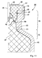
- the planar rim portion 126 of stopper 125 has at least a portion 128 which is piercable by a hollow needle 141 having a sharpened end at its proximal end tip 142 as shown in Fig. 11 .
- Hollow needle 141 is used for transferring the liquid medicament contained in cartridge 111 to another container, e.g. to the chamber of a syringe, or is used for injecting the liquid medicament into a patient.
- Piston 121 has a recess 122 for accommodating the needle tip which is advantageous inasmuch as once piston 121 reaches its foremost position shown in Fig. 11 , it does not abut against the proximal end tip 142 of needle 141 but rather protrusions 120 of piston 121 abut against the tips of the tubular portion 127 of stopper 125. Thus, the proximal end tip 142 of needle 141 does not come into contact with stopper 125 at any time.
- the needle is a part which is fixed in the end face of a tubular needle holder component (not represented in the drawings) which can simply be moved over the distal end 113 of barrel 112 until the needle holder component is snap-fitted onto the said distal end 113 of barrel 112.
- stopper 125 is penetrated by the needle and once the snap of the needle holder component occurs, the needle reaches into the needle space defined by the recesses of the stopper 125 and the piston 121 when the piston 121 is in its end position shown in Fig. 11 .
- FIG. 1 Another embodiment of the cartridge according to the invention which is not represented in the drawings relates to a dual chamber cartridge, with one chamber containing a lyophilized product and the other chamber containing the buffer, in which the lyophilized product is solved immediately prior to administration.
- Such an embodiment of the cartridge may comprise a similar piston, septum or stopper as described in the embodiments shown in the drawings.
- means must be provided in addition which first allow the buffer contained in one chamber to enter the other chamber containing the lyophilized product and to allow the lyophilized product to solve in the buffer, and then the cartridge may work in the manner described with reference to the drawings.
- Such additional means are well-known in the art and may comprise, by way of example, a througbore in the piston connecting the two chambers and a membrane arranged therebetween.
- a througbore in the piston connecting the two chambers and a membrane arranged therebetween.
- the membrane in the piston ruptures so that the buffer flows through the throughbore in the piston and enters the other chamber containing the lypohilized product. Further movement of the plunger rod towards the piston causes the remaining buffer to also enter the chamber containing the lyophilized product.
- the medicament can then be administered.
Priority Applications (1)
| Application Number | Priority Date | Filing Date | Title |
|---|---|---|---|
| EP09166680A EP2281542A1 (de) | 2009-07-29 | 2009-07-29 | Arzneimittelkartusche |
Applications Claiming Priority (1)
| Application Number | Priority Date | Filing Date | Title |
|---|---|---|---|
| EP09166680A EP2281542A1 (de) | 2009-07-29 | 2009-07-29 | Arzneimittelkartusche |
Publications (1)
| Publication Number | Publication Date |
|---|---|
| EP2281542A1 true EP2281542A1 (de) | 2011-02-09 |
Family
ID=41350735
Family Applications (1)
| Application Number | Title | Priority Date | Filing Date |
|---|---|---|---|
| EP09166680A Withdrawn EP2281542A1 (de) | 2009-07-29 | 2009-07-29 | Arzneimittelkartusche |
Country Status (1)
| Country | Link |
|---|---|
| EP (1) | EP2281542A1 (de) |
Citations (2)
| Publication number | Priority date | Publication date | Assignee | Title |
|---|---|---|---|---|
| EP0001452A1 (de) * | 1977-10-11 | 1979-04-18 | BioNexus, Inc. | Ampulle für das langfristige Aufbewahren polymerisierbarer Substanzen |
| WO2008127345A1 (en) * | 2006-07-11 | 2008-10-23 | Eli Lilly And Company | Medication cartridge piston |
-
2009
- 2009-07-29 EP EP09166680A patent/EP2281542A1/de not_active Withdrawn
Patent Citations (2)
| Publication number | Priority date | Publication date | Assignee | Title |
|---|---|---|---|---|
| EP0001452A1 (de) * | 1977-10-11 | 1979-04-18 | BioNexus, Inc. | Ampulle für das langfristige Aufbewahren polymerisierbarer Substanzen |
| WO2008127345A1 (en) * | 2006-07-11 | 2008-10-23 | Eli Lilly And Company | Medication cartridge piston |
Similar Documents
| Publication | Publication Date | Title |
|---|---|---|
| US8469923B2 (en) | Cartridge for powder and liquid drug | |
| US5549561A (en) | Injection cartridge arrangement | |
| US8092421B2 (en) | Dual-chamber carpule | |
| JP4682850B2 (ja) | プレフィルドシリンジ | |
| US6740062B2 (en) | Medical device | |
| US7727183B2 (en) | Syringe assembly | |
| EP1284764B1 (de) | Medizinische vorrichtung | |
| EP2296797B1 (de) | Zahnstangengetriebe für bypasskartusche | |
| US20120136298A1 (en) | Mixing device with piston coupling arrangement | |
| JP4838304B2 (ja) | 中空針を有する容器 | |
| EP3065801B1 (de) | Ausgabevorrichtung mit mischung von pharmazeutischen bestandteilen | |
| MXPA03008268A (es) | Inyector con diluyente de seguridad pre-cargado. | |
| JP2007185319A5 (de) | ||
| JPH10295814A (ja) | カニューレ密封シールドアセンブリ | |
| JPH0360510B2 (de) | ||
| US8974407B2 (en) | Buffering agent delivery system for anesthetic syringe | |
| US20150088089A1 (en) | Reconstitution device | |
| US20150343153A1 (en) | Dual chamber mixing syringes and methods of using same | |
| US8690837B2 (en) | Mixing device for a two-chamber ampoule | |
| CN113498351B (zh) | 用于医用注射装置的阀门塞子和用于注射至少一种组分的医用注射装置 | |
| IL46017A (en) | Two-chamber mixing syringe | |
| EP3473281B1 (de) | Einfüllhilfe und verfahren zur selbstbefüllung einer kartusche | |
| US20220339360A1 (en) | Control mechanism for priming an injection device | |
| US9833572B2 (en) | Modular dual chamber syringe system | |
| US9867944B1 (en) | Multi-mode medication dispenser |
Legal Events
| Date | Code | Title | Description |
|---|---|---|---|
| PUAI | Public reference made under article 153(3) epc to a published international application that has entered the european phase |
Free format text: ORIGINAL CODE: 0009012 |
|
| AK | Designated contracting states |
Kind code of ref document: A1 Designated state(s): AT BE BG CH CY CZ DE DK EE ES FI FR GB GR HR HU IE IS IT LI LT LU LV MC MK MT NL NO PL PT RO SE SI SK SM TR |
|
| AX | Request for extension of the european patent |
Extension state: AL BA RS |
|
| STAA | Information on the status of an ep patent application or granted ep patent |
Free format text: STATUS: THE APPLICATION IS DEEMED TO BE WITHDRAWN |
|
| 18D | Application deemed to be withdrawn |
Effective date: 20110810 |