EP2281509A1 - Setting a Sagittal View in an Ultrasound System - Google Patents
Setting a Sagittal View in an Ultrasound System Download PDFInfo
- Publication number
- EP2281509A1 EP2281509A1 EP20100159227 EP10159227A EP2281509A1 EP 2281509 A1 EP2281509 A1 EP 2281509A1 EP 20100159227 EP20100159227 EP 20100159227 EP 10159227 A EP10159227 A EP 10159227A EP 2281509 A1 EP2281509 A1 EP 2281509A1
- Authority
- EP
- European Patent Office
- Prior art keywords
- window
- ultrasound
- slice
- volume data
- sagittal view
- Prior art date
- Legal status (The legal status is an assumption and is not a legal conclusion. Google has not performed a legal analysis and makes no representation as to the accuracy of the status listed.)
- Granted
Links
Images



Classifications
-
- A—HUMAN NECESSITIES
- A61—MEDICAL OR VETERINARY SCIENCE; HYGIENE
- A61B—DIAGNOSIS; SURGERY; IDENTIFICATION
- A61B8/00—Diagnosis using ultrasonic, sonic or infrasonic waves
-
- A—HUMAN NECESSITIES
- A61—MEDICAL OR VETERINARY SCIENCE; HYGIENE
- A61B—DIAGNOSIS; SURGERY; IDENTIFICATION
- A61B8/00—Diagnosis using ultrasonic, sonic or infrasonic waves
- A61B8/08—Clinical applications
- A61B8/0858—Clinical applications involving measuring tissue layers, e.g. skin, interfaces
-
- A—HUMAN NECESSITIES
- A61—MEDICAL OR VETERINARY SCIENCE; HYGIENE
- A61B—DIAGNOSIS; SURGERY; IDENTIFICATION
- A61B8/00—Diagnosis using ultrasonic, sonic or infrasonic waves
- A61B8/46—Ultrasonic, sonic or infrasonic diagnostic devices with special arrangements for interfacing with the operator or the patient
- A61B8/467—Ultrasonic, sonic or infrasonic diagnostic devices with special arrangements for interfacing with the operator or the patient characterised by special input means
-
- A—HUMAN NECESSITIES
- A61—MEDICAL OR VETERINARY SCIENCE; HYGIENE
- A61B—DIAGNOSIS; SURGERY; IDENTIFICATION
- A61B8/00—Diagnosis using ultrasonic, sonic or infrasonic waves
- A61B8/48—Diagnostic techniques
- A61B8/483—Diagnostic techniques involving the acquisition of a 3D volume of data
-
- A—HUMAN NECESSITIES
- A61—MEDICAL OR VETERINARY SCIENCE; HYGIENE
- A61B—DIAGNOSIS; SURGERY; IDENTIFICATION
- A61B8/00—Diagnosis using ultrasonic, sonic or infrasonic waves
- A61B8/52—Devices using data or image processing specially adapted for diagnosis using ultrasonic, sonic or infrasonic waves
- A61B8/5215—Devices using data or image processing specially adapted for diagnosis using ultrasonic, sonic or infrasonic waves involving processing of medical diagnostic data
- A61B8/523—Devices using data or image processing specially adapted for diagnosis using ultrasonic, sonic or infrasonic waves involving processing of medical diagnostic data for generating planar views from image data in a user selectable plane not corresponding to the acquisition plane
-
- G—PHYSICS
- G06—COMPUTING OR CALCULATING; COUNTING
- G06T—IMAGE DATA PROCESSING OR GENERATION, IN GENERAL
- G06T17/00—Three-dimensional [3D] modelling for computer graphics
-
- A—HUMAN NECESSITIES
- A61—MEDICAL OR VETERINARY SCIENCE; HYGIENE
- A61B—DIAGNOSIS; SURGERY; IDENTIFICATION
- A61B8/00—Diagnosis using ultrasonic, sonic or infrasonic waves
- A61B8/46—Ultrasonic, sonic or infrasonic diagnostic devices with special arrangements for interfacing with the operator or the patient
- A61B8/467—Ultrasonic, sonic or infrasonic diagnostic devices with special arrangements for interfacing with the operator or the patient characterised by special input means
- A61B8/469—Ultrasonic, sonic or infrasonic diagnostic devices with special arrangements for interfacing with the operator or the patient characterised by special input means for selection of a region of interest
Definitions
- the present disclosure generally relates to ultrasound systems, and more particularly to setting a sagittal view for measuring a thickness of a nuchal translucency (NT) of a fetus in an ultrasound system.
- NT nuchal translucency
- An ultrasound system has become an important and popular diagnostic tool since it has a wide range of applications. Specifically, due to its non-invasive and non-destructive nature, the ultrasound system has been extensively used in the medical profession. Modem high-performance ultrasound systems and techniques are commonly used to produce two or three-dimensional diagnostic images of internal features of an object (e.g., human organs).
- an object e.g., human organs
- the ultrasound system transmits and receives ultrasound signals to and from a target object (e.g., a fetus) to thereby form a 2D (two-dimensional) ultrasound image of the fetus.
- a target object e.g., a fetus
- the ultrasound system may check a chromosomal abnormality of the fetus by measuring the thickness of the NT based on the sagittal view.
- the thickness of the NT may not be measured exactly.
- an ultrasound system comprises: an ultrasound data acquisition unit configured to transmit and receive ultrasound signals to and from a target object to thereby output ultrasound data; and a processing unit configured to form volume data based on the ultrasound data, the processing unit being configured to set a reference slice, a reference point and a window on the volume data based on input information of a user, and the processing unit being further configured to set a sagittal view for measuring a thickness of a nuchal translucency (NT) of a fetus on the volume data.
- NT nuchal translucency
- a method of setting a sagittal view comprising: a) transmitting and receiving ultrasound signals to and from a target object to thereby output ultrasound data; b) forming volume data based on the ultrasound data; c) setting a reference slice, a reference point and a window on the volume data based on input information of a user; and d) setting a sagittal view for measuring a thickness of a nuchal translucency (NT) of a fetus on the volume data based on the reference slice, the reference point and the window.
- NT nuchal translucency
- the ultrasound system 100 may include an ultrasound data acquisition unit 110.
- the ultrasound data acquisition unit 110 may be operable to transmit and receive ultrasound signals to and from a target object (e.g., a fetus) to thereby output ultrasound data.
- the ultrasound data acquisition unit 110 may include a transmit (Tx) signal generating section 111, as shown in Figure 2 .
- FIG 2 is a block diagram showing an illustrative embodiment of the ultrasound data acquisition unit 110.
- the Tx signal generating section 111 may be operable to generate Tx signals.
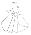
- the Tx signal generating section 111 may generate the Tx signals at every predetermined time to thereby form a plurality of Tx signals for obtaining each of frames F i (1 ⁇ i ⁇ N) representing the target object, as shown in Figure 3 .
- Figure 3 is a schematic diagram showing an example of acquiring ultrasound data corresponding to a plurality of frames F i (1 ⁇ i ⁇ N).
- the plurality of frames F i (1 ⁇ i ⁇ N) may represent sectional planes of the target object (not shown).
- the ultrasound data acquisition unit 110 may further include an ultrasound probe 112 containing a plurality of elements for reciprocally converting between ultrasound signals and electrical signals.
- the ultrasound probe 112 may be operable to transmit ultrasound signals into the target object in response to the Tx signals.
- the ultrasound probe 112 may further receive echo signals reflected from the target object to thereby output received signals.
- the received signals may be analog signals.
- the ultrasound probe 112 may include a three-dimensional mechanical probe, a two-dimensional array probe or the like. However, the ultrasound probe 112 may not be limited thereto.
- the ultrasound data acquisition unit 110 may further include a beam former 113.
- the beam former 113 may be operable to convert the received signals into digital signals.
- the beam former 113 may further apply delays to the digital signals in consideration of distances between the elements and focal points to thereby output digital receive-focused signals.
- the ultrasound data acquisition unit 110 may further include an ultrasound data forming section 114.
- the ultrasound data forming section 114 may be operable to form ultrasound data corresponding to each of the frames F i (1 ⁇ i ⁇ N) based on the digital receive-focused signals.
- the ultrasound data forming unit 114 may be further operable to perform various signal processing (e.g., gain adjustment) to the digital receive-focused signals.
- the ultrasound system 100 may further include a processing unit 120, which may be coupled to the ultrasound data acquisition unit 110.
- Figure 4 is a block diagram showing an illustrative embodiment of the processing unit 120.
- the processing unit 120 may include a volume data forming section 121, a reference slice setting section 122, a reference point setting section 123, a window setting section 124, a sagittal view setting section 125, an image forming section 126 and a nuchal translucency (NT) thickness measuring section 127.
- NT nuchal translucency
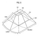
- the volume data forming section 121 may synthesize the ultrasound data corresponding to the frames F i (1 ⁇ i ⁇ N) to thereby form volume data including the frames F i (1 ⁇ i ⁇ N), as shown in Figure 5.
- Figure 5 is a schematic diagram showing an example of volume data 210.
- the volume data 210 may include a plurality of voxels having brightness values.
- reference numerals 221 to 223 represent an A plane, a B plane and a C plane.
- the A plane 221, the B plane 222 and the C plane 223 may be mutually orthogonal.
- the axial direction may be a Tx direction of the ultrasound signals
- the lateral direction may be a longitudinal direction of the transducer
- the elevation direction may be a swing direction of the transducer, i.e., a depth direction of a 3D (three-dimensional) ultrasound image.
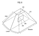
- the reference slice setting section 122 may set a reference slice 230 on the volume data 210 based on input information provided from a user input unit 130, as shown in Figure 6.
- Figure 6 is a schematic diagram showing an example of a reference slice 230, a reference point 240 and a window 250, which are set on the volume data 210.
- the reference slice 230 in Figure 6 may be the B plane 222 as shown in Figure 5 .
- the reference slice 230 may not be limited thereto.
- the reference point setting section 123 may set a reference point 240 on the reference slice 230 based on the input information provided from the user input unit 130, as shown in Figure 6 .
- the window setting section 124 may be operable to set a window 250 to encompass the reference point 240 on the reference slice 230 as shown in Figure 6 .
- the window 250 may be a rectangular window having a predetermined size. However, the window 250 may not be limited thereto.
- the sagittal view setting section 125 may set a sagittal view on the volume data 210 based on the reference slice 230, the reference point 240 and the window 250.
- the sagittal view may be a slice for measuring a thickness of the NT of a fetus. However, the sagittal view may not be limited thereto.
- the sagittal view setting section 125 may be operable to detect brightness values of pixels within the window 250 set on the reference slice 230.
- the sagittal view setting section 125 may be further operable to calculate a reference value based on the brightness values.
- the reference value may be a mean value of the brightness values or a sum value of the brightness values. However, the reference value may not be limited thereto.
- the sagittal view setting section 125 may further move the reference slice 230, the reference point 240 and the window 250 to the lateral direction by predetermined intervals within the volume data 210 to thereby calculate the reference values. Positions of the moved reference slice 230 and the calculated reference values may be stored in a storage unit 140.
- the sagittal view setting section 125 may be further operable to compare the calculated reference values to thereby detect a maximum reference value.
- the sagittal view setting section 125 may also move the reference slice 230, the reference point 240 and the window 250 to a position corresponding to the maximum reference value.
- the sagittal view setting section 125 may further rotate the reference slice 230 and the window 250 to the axial direction by predetermined angles with respect to the reference point 240 to thereby calculate the reference values. Positions of the rotated reference slice 230 and the calculated reference values may be stored in a storage unit 140.
- the sagittal view setting section 125 may be further operable to compare the calculated reference values to thereby detect a maximum reference value.
- the sagittal view setting section 125 may be further operable to rotate the reference slice 230 and the window 250 to a position corresponding to the maximum reference value.
- the sagittal view setting section 125 may rotate the reference slice 230 and the window 250 to the elevation direction by predetermined angles with respect to the reference point 240 to thereby calculate the reference values.
- the sagittal view setting section 125 may be further operable to compare the calculated reference values to thereby detect a maximum reference value.
- the sagittal view setting section 125 may rotate the reference slice 230 and the window 250 to a position corresponding to the maximum reference value.
- the sagittal view setting section 125 may set the sagittal view on the volume data 210 based on the reference slice 230.
- the sagittal view may include the reference point 240 and the window 250.
- the sagittal view setting section 125 may be operable to set the reference slice 230 as the sagittal view on the volume data 210.
- the sagittal view setting section 125 may set the mean value of the brightness values or the sum value of the brightness values as the reference value in the foregoing embodiment, the sagittal view setting section 125 may further calculate a gradient magnitude and an orientation for each of the pixels within the window 250, form a histogram between the gradient magnitudes and the orientations, detect a peak in the histogram and set the detected peak as the reference value.
- the sagittal view setting section 125 may move the reference slice 230 to the lateral direction and rotate the reference slice 230 to the axial direction and the elevation direction in the foregoing embodiment, the sagittal view setting section 125 may further move and rotate the reference slice 230 to arbitrary directions.
- the sagittal view setting section 125 may rotate the reference slice 230 with respect to the reference point 240 in the foregoing embodiment, the sagittal view setting section 125 may further rotate the volume data 210 with respect to the reference point 240.
- the image forming section 126 may form a 2D (two-dimensional) ultrasound image 310 corresponding to the sagittal view based on the volume data 210 as shown in Figure 7.
- Figure 7 is a schematic diagram showing an example of the ultrasound image 310, the reference point 240 and the window 250.
- the 2D ultrasound image 310 may be a brightness mode image.
- the image forming section 126 may be further operable to render the volume data 210 to thereby form a 3D (three-dimensional) ultrasound image (not shown).
- the NT thickness measuring section 127 may be configured to set the reference point 240 and the window 250 on the 2D ultrasound image 310 based on the sagittal view.
- the NT thickness measuring section 127 may be further configured to detect a contour of the NT 320 within the window 250.
- the contour may be detected by using an edge mask such as Sobel, Prewitt, Robert, Canny mask or the like.
- the contour may be detected based on the differences between eigenvalues using structure tensors.
- the NT thickness measuring section 127 may measure a thickness of the NT based on the detected contour to thereby output measurement information.
- the methods of measuring the thickness of the NT based on the contour are well known in the art. Thus, they have not been described in detail so as not to unnecessarily obscure the present invention.
- the ultrasound system 100 may further include the user input unit 130.
- the user input unit 130 may be operable to receive input information of a user.
- the input information may include first input information for setting the reference slice on the volume data and second input information for setting the reference point on the NT of the reference slice.
- the user input unit 130 may include a control panel, a mouse, a keyboard or the like. However, the user input unit 130 may not be limited thereto.
- the ultrasound system 100 may further include the storage unit 140.
- the storage unit 140 may store the positions of the reference slice 230 and the reference values.
- the storage unit 140 may further store the volume data 210.
- the ultrasound system may further include a display unit 150.
- the display unit 150 may display the 2D ultrasound image, the 3D ultrasound image and the measurement information.
Landscapes
- Life Sciences & Earth Sciences (AREA)
- Health & Medical Sciences (AREA)
- Engineering & Computer Science (AREA)
- Physics & Mathematics (AREA)
- Molecular Biology (AREA)
- Surgery (AREA)
- Nuclear Medicine, Radiotherapy & Molecular Imaging (AREA)
- Pathology (AREA)
- Radiology & Medical Imaging (AREA)
- Biomedical Technology (AREA)
- Heart & Thoracic Surgery (AREA)
- Medical Informatics (AREA)
- Veterinary Medicine (AREA)
- Biophysics (AREA)
- Animal Behavior & Ethology (AREA)
- General Health & Medical Sciences (AREA)
- Public Health (AREA)
- Computer Vision & Pattern Recognition (AREA)
- Computer Graphics (AREA)
- Geometry (AREA)
- Software Systems (AREA)
- General Physics & Mathematics (AREA)
- Theoretical Computer Science (AREA)
- Ultra Sonic Daignosis Equipment (AREA)
Abstract
Description
- The present application claims priority from Korean Patent Application No.
10-2009-0069867 filed on July 30, 2009 - The present disclosure generally relates to ultrasound systems, and more particularly to setting a sagittal view for measuring a thickness of a nuchal translucency (NT) of a fetus in an ultrasound system.
- An ultrasound system has become an important and popular diagnostic tool since it has a wide range of applications. Specifically, due to its non-invasive and non-destructive nature, the ultrasound system has been extensively used in the medical profession. Modem high-performance ultrasound systems and techniques are commonly used to produce two or three-dimensional diagnostic images of internal features of an object (e.g., human organs).
- The ultrasound system transmits and receives ultrasound signals to and from a target object (e.g., a fetus) to thereby form a 2D (two-dimensional) ultrasound image of the fetus. Also, when a user sets a sagittal view for measuring a thickness of a nuchal translucency (NT) of the fetus based on the 2D ultrasound image, the ultrasound system may check a chromosomal abnormality of the fetus by measuring the thickness of the NT based on the sagittal view. However, it may be difficult to precisely set the sagittal view on volume data. Thus, there is a problem in that the thickness of the NT may not be measured exactly.
- Embodiments for providing a plurality of slice images in an ultrasound system are disclosed herein. In one embodiment, by way of non-limiting example, an ultrasound system comprises: an ultrasound data acquisition unit configured to transmit and receive ultrasound signals to and from a target object to thereby output ultrasound data; and a processing unit configured to form volume data based on the ultrasound data, the processing unit being configured to set a reference slice, a reference point and a window on the volume data based on input information of a user, and the processing unit being further configured to set a sagittal view for measuring a thickness of a nuchal translucency (NT) of a fetus on the volume data.
- In another embodiment, there is provided a method of setting a sagittal view, comprising: a) transmitting and receiving ultrasound signals to and from a target object to thereby output ultrasound data; b) forming volume data based on the ultrasound data; c) setting a reference slice, a reference point and a window on the volume data based on input information of a user; and d) setting a sagittal view for measuring a thickness of a nuchal translucency (NT) of a fetus on the volume data based on the reference slice, the reference point and the window.
- The Summary is provided to introduce a selection of concepts in a simplified form that are further described below in the Detailed Description. This Summary is not intended to identify key or essential features of the claimed subject matter, nor is it intended to be used in determining the scope of the claimed subject matter.
-
-
Figure 1 is a block diagram showing an illustrative embodiment of an ultrasound system. -
Figure 2 is a block diagram showing an illustrative embodiment of an ultrasound data acquisition unit. -
Figure 3 is a schematic diagram showing an example of acquiring ultrasound data corresponding to a plurality of frames. -
Figure 4 is a block diagram showing an illustrative embodiment of a processing unit. -
Figure 5 is a schematic diagram showing an example of volume data. -
Figure 6 is a schematic diagram showing an example of a reference slice, a reference point and a window set on the volume data. -
Figure 7 is a schematic diagram showing an example of an ultrasound image, the reference point and the window. - A detailed description may be provided with reference to the accompanying drawings. One of ordinary skill in the art may realize that the following description is illustrative only and is not in any way limiting. Other embodiments of the present invention may readily suggest themselves to such skilled persons having the benefit of this disclosure.
- Referring to
Figure 1 , anultrasound system 100 in accordance with an illustrative embodiment is shown. As depicted therein, theultrasound system 100 may include an ultrasounddata acquisition unit 110. The ultrasounddata acquisition unit 110 may be operable to transmit and receive ultrasound signals to and from a target object (e.g., a fetus) to thereby output ultrasound data. The ultrasounddata acquisition unit 110 may include a transmit (Tx) signal generatingsection 111, as shown inFigure 2 . -
Figure 2 is a block diagram showing an illustrative embodiment of the ultrasounddata acquisition unit 110. Referring toFigure 2 , the Txsignal generating section 111 may be operable to generate Tx signals. The Txsignal generating section 111 may generate the Tx signals at every predetermined time to thereby form a plurality of Tx signals for obtaining each of frames Fi (1≤ i ≤ N) representing the target object, as shown inFigure 3 . -
Figure 3 is a schematic diagram showing an example of acquiring ultrasound data corresponding to a plurality of frames Fi (1≤i≤N). The plurality of frames Fi (1≤i≤ N) may represent sectional planes of the target object (not shown). - Referring back to
Figure 2 , the ultrasounddata acquisition unit 110 may further include anultrasound probe 112 containing a plurality of elements for reciprocally converting between ultrasound signals and electrical signals. Theultrasound probe 112 may be operable to transmit ultrasound signals into the target object in response to the Tx signals. Theultrasound probe 112 may further receive echo signals reflected from the target object to thereby output received signals. The received signals may be analog signals. Theultrasound probe 112 may include a three-dimensional mechanical probe, a two-dimensional array probe or the like. However, theultrasound probe 112 may not be limited thereto. - The ultrasound
data acquisition unit 110 may further include a beam former 113. The beam former 113 may be operable to convert the received signals into digital signals. The beam former 113 may further apply delays to the digital signals in consideration of distances between the elements and focal points to thereby output digital receive-focused signals. - The ultrasound
data acquisition unit 110 may further include an ultrasounddata forming section 114. The ultrasounddata forming section 114 may be operable to form ultrasound data corresponding to each of the frames Fi (1≤i≤N) based on the digital receive-focused signals. The ultrasounddata forming unit 114 may be further operable to perform various signal processing (e.g., gain adjustment) to the digital receive-focused signals. - Referring back to
Figure 1 , theultrasound system 100 may further include aprocessing unit 120, which may be coupled to the ultrasounddata acquisition unit 110.Figure 4 is a block diagram showing an illustrative embodiment of theprocessing unit 120. Referring toFigure 4 , theprocessing unit 120 may include a volumedata forming section 121, a referenceslice setting section 122, a referencepoint setting section 123, awindow setting section 124, a sagittalview setting section 125, animage forming section 126 and a nuchal translucency (NT)thickness measuring section 127. - The volume
data forming section 121 may synthesize the ultrasound data corresponding to the frames Fi (1≤i≤N) to thereby form volume data including the frames Fi (1≤i≤N), as shown inFigure 5. Figure 5 is a schematic diagram showing an example ofvolume data 210. Thevolume data 210 may include a plurality of voxels having brightness values. InFigure 5 ,reference numerals 221 to 223 represent an A plane, a B plane and a C plane. TheA plane 221, theB plane 222 and theC plane 223 may be mutually orthogonal. Also, inFigure 5 , the axial direction may be a Tx direction of the ultrasound signals, the lateral direction may be a longitudinal direction of the transducer and the elevation direction may be a swing direction of the transducer, i.e., a depth direction of a 3D (three-dimensional) ultrasound image. - The reference
slice setting section 122 may set areference slice 230 on thevolume data 210 based on input information provided from auser input unit 130, as shown inFigure 6. Figure 6 is a schematic diagram showing an example of areference slice 230, areference point 240 and awindow 250, which are set on thevolume data 210. In one embodiment, thereference slice 230 inFigure 6 may be theB plane 222 as shown inFigure 5 . However, thereference slice 230 may not be limited thereto. - Referring back to
Figure 4 , the referencepoint setting section 123 may set areference point 240 on thereference slice 230 based on the input information provided from theuser input unit 130, as shown inFigure 6 . - The
window setting section 124 may be operable to set awindow 250 to encompass thereference point 240 on thereference slice 230 as shown inFigure 6 . In one embodiment, thewindow 250 may be a rectangular window having a predetermined size. However, thewindow 250 may not be limited thereto. - The sagittal
view setting section 125 may set a sagittal view on thevolume data 210 based on thereference slice 230, thereference point 240 and thewindow 250. The sagittal view may be a slice for measuring a thickness of the NT of a fetus. However, the sagittal view may not be limited thereto. - In one embodiment, the sagittal
view setting section 125 may be operable to detect brightness values of pixels within thewindow 250 set on thereference slice 230. The sagittalview setting section 125 may be further operable to calculate a reference value based on the brightness values. The reference value may be a mean value of the brightness values or a sum value of the brightness values. However, the reference value may not be limited thereto. The sagittalview setting section 125 may further move thereference slice 230, thereference point 240 and thewindow 250 to the lateral direction by predetermined intervals within thevolume data 210 to thereby calculate the reference values. Positions of the movedreference slice 230 and the calculated reference values may be stored in astorage unit 140. The sagittalview setting section 125 may be further operable to compare the calculated reference values to thereby detect a maximum reference value. The sagittalview setting section 125 may also move thereference slice 230, thereference point 240 and thewindow 250 to a position corresponding to the maximum reference value. The sagittalview setting section 125 may further rotate thereference slice 230 and thewindow 250 to the axial direction by predetermined angles with respect to thereference point 240 to thereby calculate the reference values. Positions of the rotatedreference slice 230 and the calculated reference values may be stored in astorage unit 140. The sagittalview setting section 125 may be further operable to compare the calculated reference values to thereby detect a maximum reference value. The sagittalview setting section 125 may be further operable to rotate thereference slice 230 and thewindow 250 to a position corresponding to the maximum reference value. The sagittalview setting section 125 may rotate thereference slice 230 and thewindow 250 to the elevation direction by predetermined angles with respect to thereference point 240 to thereby calculate the reference values. The sagittalview setting section 125 may be further operable to compare the calculated reference values to thereby detect a maximum reference value. The sagittalview setting section 125 may rotate thereference slice 230 and thewindow 250 to a position corresponding to the maximum reference value. Thus, the sagittalview setting section 125 may set the sagittal view on thevolume data 210 based on thereference slice 230. The sagittal view may include thereference point 240 and thewindow 250. For example, the sagittalview setting section 125 may be operable to set thereference slice 230 as the sagittal view on thevolume data 210. - While the sagittal
view setting section 125 may set the mean value of the brightness values or the sum value of the brightness values as the reference value in the foregoing embodiment, the sagittalview setting section 125 may further calculate a gradient magnitude and an orientation for each of the pixels within thewindow 250, form a histogram between the gradient magnitudes and the orientations, detect a peak in the histogram and set the detected peak as the reference value. - Also, while the sagittal
view setting section 125 may move thereference slice 230 to the lateral direction and rotate thereference slice 230 to the axial direction and the elevation direction in the foregoing embodiment, the sagittalview setting section 125 may further move and rotate thereference slice 230 to arbitrary directions. - Further, while the sagittal
view setting section 125 may rotate thereference slice 230 with respect to thereference point 240 in the foregoing embodiment, the sagittalview setting section 125 may further rotate thevolume data 210 with respect to thereference point 240. - The
image forming section 126 may form a 2D (two-dimensional)ultrasound image 310 corresponding to the sagittal view based on thevolume data 210 as shown inFigure 7. Figure 7 is a schematic diagram showing an example of theultrasound image 310, thereference point 240 and thewindow 250. The2D ultrasound image 310 may be a brightness mode image. Theimage forming section 126 may be further operable to render thevolume data 210 to thereby form a 3D (three-dimensional) ultrasound image (not shown). - The NT
thickness measuring section 127 may be configured to set thereference point 240 and thewindow 250 on the2D ultrasound image 310 based on the sagittal view. The NTthickness measuring section 127 may be further configured to detect a contour of theNT 320 within thewindow 250. The contour may be detected by using an edge mask such as Sobel, Prewitt, Robert, Canny mask or the like. The contour may be detected based on the differences between eigenvalues using structure tensors. The NTthickness measuring section 127 may measure a thickness of the NT based on the detected contour to thereby output measurement information. The methods of measuring the thickness of the NT based on the contour are well known in the art. Thus, they have not been described in detail so as not to unnecessarily obscure the present invention. - Referring back to
Figure 1 , theultrasound system 100 may further include theuser input unit 130. Theuser input unit 130 may be operable to receive input information of a user. In one embodiment, the input information may include first input information for setting the reference slice on the volume data and second input information for setting the reference point on the NT of the reference slice. Theuser input unit 130 may include a control panel, a mouse, a keyboard or the like. However, theuser input unit 130 may not be limited thereto. - The
ultrasound system 100 may further include thestorage unit 140. Thestorage unit 140 may store the positions of thereference slice 230 and the reference values. Thestorage unit 140 may further store thevolume data 210. - The ultrasound system may further include a
display unit 150. Thedisplay unit 150 may display the 2D ultrasound image, the 3D ultrasound image and the measurement information. - Although embodiments have been described with reference to a number of illustrative embodiments thereof, it should be understood that numerous other modifications and embodiments can be devised by those skilled in the art that will fall within the spirit and scope of the principles of this disclosure. More particularly, numerous variations and modifications are possible in the component parts and/or arrangements of the subject combination arrangement within the scope of the disclosure, the drawings and the appended claims. In addition to variations and modifications in the component parts and/or arrangements, alternative uses will also be apparent to those skilled in the art.
Claims (15)
- An ultrasound system, comprising:an ultrasound data acquisition unit configured to transmit and receive ultrasound signals to and from a target object to thereby output ultrasound data; anda processing unit placed in communication with the ultrasound data acquisition unit and being configured to form volume data based on the ultrasound data, set a reference slice, a reference point and a window on the volume data based on input information of a user, and set a sagittal view for measuring a thickness of a nuchal translucency (NT) of a fetus on the volume data.
- The ultrasound system of Claim 1, further comprising a user input unit placed in communication with the processing unit and being configured to receive the input information.
- The ultrasound system of Claim 1, wherein the input information comprises:a first input information for setting the reference slice on the volume data; anda second input information for setting the reference point on the reference slice.
- The ultrasound system of Claim 1, wherein the processing unit comprises:a volume data forming section configured to form the volume data based on the ultrasound data;a reference slice setting section configured to set the reference slice on the volume data based on the input information;a reference point setting section configured to set the reference point on the reference slice based on the input information;a window setting section configured to set the window to encompass the reference point on the reference slice; anda sagittal view setting section configured to set the sagittal view on the volume data based on the reference slice, the reference point and the window.
- The ultrasound system of Claim 4, wherein the sagittal view setting section is configured to:move the reference slice, the reference point and the window to a first direction by predetermined intervals to thereby calculate first reference values;detect a maximum first reference value from the first reference values;move the reference slice, the reference point and the window to a position corresponding to the maximum first reference value;rotate the reference slice and the window by predetermined angles with respect to the reference point to thereby calculate second reference values;detect a maximum second reference value from the second reference values; androtate the reference slice and the window to a position corresponding to the maximum second reference value to thereby set the sagittal view on the volume data.
- The ultrasound system of Claim 5, wherein the sagittal view setting section is configured to detect brightness values of pixels within the window, calculate a mean value of the brightness values and set the mean value as the first or second reference value.
- The ultrasound system of Claim 5, wherein the sagittal view setting section is configured to detect brightness values of pixels within the window, calculate a sum value of the brightness values and set the sum value as the first or second reference value.
- The ultrasound system of Claim 5, wherein the sagittal view setting section is configured to calculate a gradient magnitude and an orientation for pixels within the window, form a histogram between the gradient magnitude and the orientation, detect a peak in the histogram and set the detected peak as the first or second reference value.
- The ultrasound system of Claim 4, wherein the processing unit further comprises:an image forming section configured to form an ultrasound image corresponding to the sagittal view based on the volume data; anda NT thickness measuring section configured to detect a contour of the NT within the window at the ultrasound image and measure thickness of the NT based on the detected contour.
- A method of setting a sagittal view, comprising:a) transmitting and receiving ultrasound signals to and from a target object to thereby output ultrasound data;b) forming volume data based on the ultrasound data;c) setting a reference slice, a reference point and a window on the volume data based on input information of a user; andd) setting a sagittal view for measuring a thickness of a nuchal translucency (NT) of a fetus on the volume data based on the reference slice, the reference point and the window.
- The method of Claim 10, wherein the input information comprises:first input information for setting the reference slice on the volume data; andsecond input information for setting the reference point on the reference slice.
- The method of Claim 10, wherein the step c) comprises:setting the reference slice on the volume data based on the input information;setting the reference point on the reference slice based on the input information; andsetting the window to encompass the reference point on the reference slice.
- The method of Claim 10, wherein the step d) comprises:d1) moving the reference slice, the reference point and the window to a first direction by predetermined intervals to thereby calculate first reference value;d2) detecting a maximum first reference value from the first reference values;d3) moving the reference slice, the reference point and the window to a position corresponding to the maximum first reference value;d4) rotating the reference slice and the window to a second direction by predetermined angles with respect to the reference point to thereby calculate second reference value;d5) detecting a maximum second reference value from the second reference values; andd6) rotating the reference slice and the window to a position corresponding to the maximum second reference value to thereby set the sagittal view on the volume data.
- The method of Claim 13, wherein the first or second reference value is set based on one of a mean value of brightness values of pixels within the window, a sum value of brightness values of pixels within the window and a peak in a histogram between a gradient magnitude and an orientation for each of pixels within the window.
- The method of Claim 10, further comprising the steps of:e) forming an ultrasound image corresponding to the sagittal view based on the volume data;f) detecting a contour of the NT within the window at the ultrasound image; andg) measuring thickness of the NT based on the detected contour.
Applications Claiming Priority (1)
| Application Number | Priority Date | Filing Date | Title |
|---|---|---|---|
| KR20090069867A KR101117916B1 (en) | 2009-07-30 | 2009-07-30 | Ultrasound system and method for detecting sagittal view |
Publications (2)
| Publication Number | Publication Date |
|---|---|
| EP2281509A1 true EP2281509A1 (en) | 2011-02-09 |
| EP2281509B1 EP2281509B1 (en) | 2020-06-03 |
Family
ID=42983833
Family Applications (1)
| Application Number | Title | Priority Date | Filing Date |
|---|---|---|---|
| EP10159227.7A Active EP2281509B1 (en) | 2009-07-30 | 2010-04-07 | Setting a Sagittal View in an Ultrasound System |
Country Status (4)
| Country | Link |
|---|---|
| US (1) | US9216007B2 (en) |
| EP (1) | EP2281509B1 (en) |
| JP (1) | JP2011031023A (en) |
| KR (1) | KR101117916B1 (en) |
Cited By (3)
| Publication number | Priority date | Publication date | Assignee | Title |
|---|---|---|---|---|
| CN103263278A (en) * | 2013-01-23 | 2013-08-28 | 郑末晶 | Image processing method for automatically measuring thickness of fetal nuchal translucency from ultrasonic image |
| EP3015073A1 (en) * | 2014-10-31 | 2016-05-04 | Samsung Medison Co., Ltd. | Ultrasound imaging apparatus and method of operating the same |
| CN109640831A (en) * | 2016-09-01 | 2019-04-16 | 皇家飞利浦有限公司 | Supersonic diagnostic appts |
Families Citing this family (4)
| Publication number | Priority date | Publication date | Assignee | Title |
|---|---|---|---|---|
| KR101202533B1 (en) * | 2009-07-30 | 2012-11-16 | 삼성메디슨 주식회사 | Control device, ultrasound system, method and computer readable medium for providing a plurality of slice images |
| WO2012053612A1 (en) * | 2010-10-20 | 2012-04-26 | 株式会社東芝 | Ultrasonic diagnosis device, control method and image processing device |
| KR102150959B1 (en) * | 2013-05-31 | 2020-09-02 | 삼성메디슨 주식회사 | Method and apparatus for ultrasound diagnosis using 3d volume data |
| CN108888294B (en) * | 2018-03-30 | 2021-02-23 | 杭州依图医疗技术有限公司 | A method and device for detecting the width of the zona pellucida in the neck |
Citations (6)
| Publication number | Priority date | Publication date | Assignee | Title |
|---|---|---|---|---|
| US6102861A (en) * | 1999-04-23 | 2000-08-15 | General Electric Company | Method and apparatus for three-dimensional ultrasound imaging using surface-enhanced volume rendering |
| WO2000058754A1 (en) * | 1999-03-31 | 2000-10-05 | General Electric Company | Three-dimensional ultrasound data display using multiple cut planes |
| EP1470784A2 (en) * | 2003-04-21 | 2004-10-27 | Aloka Co., Ltd. | Ultrasonic diagnostic apparatus |
| US20070081705A1 (en) * | 2005-08-11 | 2007-04-12 | Gustavo Carneiro | System and method for fetal biometric measurements from ultrasound data and fusion of same for estimation of fetal gestational age |
| EP1923839A1 (en) | 2006-11-14 | 2008-05-21 | Aloka Co., Ltd. | Ultrasound diagnostic apparatus and volume data processing method |
| US20090074280A1 (en) * | 2007-09-18 | 2009-03-19 | Siemens Corporate Research, Inc. | Automated Detection of Planes From Three-Dimensional Echocardiographic Data |
Family Cites Families (20)
| Publication number | Priority date | Publication date | Assignee | Title |
|---|---|---|---|---|
| JP3142373B2 (en) | 1992-06-15 | 2001-03-07 | 株式会社東芝 | Image display device |
| GB9704444D0 (en) | 1997-03-04 | 1997-04-23 | Isis Innovation | Non-invasive prenatal diagnosis |
| US7113186B2 (en) | 2000-11-25 | 2006-09-26 | Infinitt Co., Ltd. | 3 Dimensional slab rendering system method and computer-readable medium |
| US8083678B2 (en) | 2003-04-16 | 2011-12-27 | Eastern Virginia Medical School | System, method and medium for acquiring and generating standardized operator independent ultrasound images of fetal, neonatal and adult organs |
| WO2004093687A1 (en) | 2003-04-16 | 2004-11-04 | Eastern Virginia Medical School | System and method for generating operator independent ultrasound images |
| JP2005102945A (en) | 2003-09-30 | 2005-04-21 | Ssb:Kk | Biotissue multidimensional visualization equipment |
| US20050281444A1 (en) | 2004-06-22 | 2005-12-22 | Vidar Lundberg | Methods and apparatus for defining a protocol for ultrasound imaging |
| US8012090B2 (en) | 2004-06-22 | 2011-09-06 | General Electric Company | Method and apparatus for real time ultrasound multi-plane imaging |
| EP1750143A3 (en) * | 2005-07-27 | 2009-09-09 | Medison Co., Ltd. | Ultrasound diagnostic system and method of automatically controlling brightness and contrast of a three-dimensional ultrasound image |
| US20070249935A1 (en) | 2006-04-20 | 2007-10-25 | General Electric Company | System and method for automatically obtaining ultrasound image planes based on patient specific information |
| US20070255139A1 (en) | 2006-04-27 | 2007-11-01 | General Electric Company | User interface for automatic multi-plane imaging ultrasound system |
| KR100803328B1 (en) * | 2006-07-06 | 2008-02-14 | 이화여자대학교 산학협력단 | Automated Measurement of Nape Stripes on Fetal Ultrasound Images |
| EP1892671A3 (en) | 2006-08-23 | 2009-07-29 | Medison Co., Ltd. | System and method for determining the volume of an object by image processing |
| JP4931676B2 (en) | 2006-11-14 | 2012-05-16 | 日立アロカメディカル株式会社 | Ultrasonic diagnostic apparatus and volume data processing method |
| JP4922006B2 (en) | 2007-02-16 | 2012-04-25 | 日立アロカメディカル株式会社 | Ultrasonic diagnostic apparatus and data processing method |
| JP2008284263A (en) | 2007-05-21 | 2008-11-27 | Panasonic Corp | Ultrasonic diagnostic equipment |
| JP5366385B2 (en) | 2007-09-26 | 2013-12-11 | 株式会社東芝 | Ultrasonic diagnostic apparatus and ultrasonic scanning program |
| KR20090095150A (en) | 2008-03-05 | 2009-09-09 | 주식회사 메디슨 | Ultrasound system and methdo for processing ultrasound image |
| WO2009136332A2 (en) * | 2008-05-09 | 2009-11-12 | Koninklijke Philips Electronics N.V. | Automatic ultrasonic measurement of nuchal fold translucency |
| KR101202533B1 (en) | 2009-07-30 | 2012-11-16 | 삼성메디슨 주식회사 | Control device, ultrasound system, method and computer readable medium for providing a plurality of slice images |
-
2009
- 2009-07-30 KR KR20090069867A patent/KR101117916B1/en active Active
-
2010
- 2010-04-07 EP EP10159227.7A patent/EP2281509B1/en active Active
- 2010-04-19 US US12/763,008 patent/US9216007B2/en active Active
- 2010-05-10 JP JP2010108320A patent/JP2011031023A/en active Pending
Patent Citations (6)
| Publication number | Priority date | Publication date | Assignee | Title |
|---|---|---|---|---|
| WO2000058754A1 (en) * | 1999-03-31 | 2000-10-05 | General Electric Company | Three-dimensional ultrasound data display using multiple cut planes |
| US6102861A (en) * | 1999-04-23 | 2000-08-15 | General Electric Company | Method and apparatus for three-dimensional ultrasound imaging using surface-enhanced volume rendering |
| EP1470784A2 (en) * | 2003-04-21 | 2004-10-27 | Aloka Co., Ltd. | Ultrasonic diagnostic apparatus |
| US20070081705A1 (en) * | 2005-08-11 | 2007-04-12 | Gustavo Carneiro | System and method for fetal biometric measurements from ultrasound data and fusion of same for estimation of fetal gestational age |
| EP1923839A1 (en) | 2006-11-14 | 2008-05-21 | Aloka Co., Ltd. | Ultrasound diagnostic apparatus and volume data processing method |
| US20090074280A1 (en) * | 2007-09-18 | 2009-03-19 | Siemens Corporate Research, Inc. | Automated Detection of Planes From Three-Dimensional Echocardiographic Data |
Non-Patent Citations (4)
| Title |
|---|
| A. S. LEV-TOAFF, S. OZHAN, D. PRETORIUS, G. BEGA, A. B. KURTZ, K. KUHLMAN: "Three-dimensional multiplanar ultrasound for fetal gender assignment: value of the mid-sagittal plane", ULTRASOUND OBSTET GYNECOL, vol. 16, 2000, pages 345 - 350, XP002612157, Retrieved from the Internet <URL:http://onlinelibrary.wiley.com/doi/10.1046/j.1469-0705.2000.00179.x/abstract> [retrieved on 20101130] * |
| ANDREW D. HULL, GINA JAMES, DOLORES H. PRETORIUS: "Detection of Jarcho-Levin syndrome at 12 weeks' gestation by nuchal translucency screening and three dimensional ultrasound", PRENATAL DIAGNOSIS, vol. 21, 11 May 2001 (2001-05-11), pages 390 - 394, XP002612156, Retrieved from the Internet <URL:http://onlinelibrary.wiley.com/doi/10.1002/pd.67/abstract> [retrieved on 20101130] * |
| HUI-XIONG XU, QING-PING ZHANG, MING-DE LU, XIAN-TAO XIAO: "Comparison of two-dimensional and three-dimensional sonography in evaluating fetal malformations", JOURNAL OF CLINICAL ULTRASOUND, vol. 30, no. 9, 25 October 2002 (2002-10-25), pages 515 - 525, XP002612158, Retrieved from the Internet <URL:http://onlinelibrary.wiley.com/doi/10.1002/jcu.10109/abstract> [retrieved on 20101120] * |
| YU-BU LEE ET AL: "Automated Ultrasonic Measurement of Fetal Nuchal Translucency Using Dynamic Programming", 1 January 2006, PROGRESS IN PATTERN RECOGNITION, IMAGE ANALYSIS AND APPLICATIONS LECTURE NOTES IN COMPUTER SCIENCE;;LNCS, SPRINGER, BERLIN, DE, PAGE(S) 157 - 167, ISBN: 978-3-540-46556-0, XP019045806 * |
Cited By (6)
| Publication number | Priority date | Publication date | Assignee | Title |
|---|---|---|---|---|
| CN103263278A (en) * | 2013-01-23 | 2013-08-28 | 郑末晶 | Image processing method for automatically measuring thickness of fetal nuchal translucency from ultrasonic image |
| CN103263278B (en) * | 2013-01-23 | 2015-05-13 | 珠海艾博罗生物技术有限公司 | Image processing method for automatically measuring thickness of fetal nuchal translucency from ultrasonic image |
| EP3015073A1 (en) * | 2014-10-31 | 2016-05-04 | Samsung Medison Co., Ltd. | Ultrasound imaging apparatus and method of operating the same |
| KR20160051160A (en) * | 2014-10-31 | 2016-05-11 | 삼성메디슨 주식회사 | ULTRASOUND IMAGE APPARATUS AND operating method for the same |
| CN109640831A (en) * | 2016-09-01 | 2019-04-16 | 皇家飞利浦有限公司 | Supersonic diagnostic appts |
| CN109640831B (en) * | 2016-09-01 | 2022-06-28 | 皇家飞利浦有限公司 | Ultrasound diagnostic equipment |
Also Published As
| Publication number | Publication date |
|---|---|
| US9216007B2 (en) | 2015-12-22 |
| JP2011031023A (en) | 2011-02-17 |
| KR101117916B1 (en) | 2012-02-24 |
| KR20110012233A (en) | 2011-02-09 |
| US20110028841A1 (en) | 2011-02-03 |
| EP2281509B1 (en) | 2020-06-03 |
Similar Documents
| Publication | Publication Date | Title |
|---|---|---|
| US8900147B2 (en) | Performing image process and size measurement upon a three-dimensional ultrasound image in an ultrasound system | |
| US20120101378A1 (en) | Providing an ultrasound spatial compound image based on a phased array probe in an ultrasound system | |
| US8915855B2 (en) | Ultrasound system and method for providing multiple plane images for a plurality of views | |
| EP2281509B1 (en) | Setting a Sagittal View in an Ultrasound System | |
| EP2289420A1 (en) | Setting an optimal image parameter in an ultrasound system | |
| US8956298B2 (en) | Providing an ultrasound spatial compound image in an ultrasound system | |
| US9069062B2 (en) | Surface rendering for volume data in an ultrasound system | |
| US20110172532A1 (en) | Automatic adjustment of scan angle, scan depth and scan speed in an ultrasound system | |
| US9151841B2 (en) | Providing an ultrasound spatial compound image based on center lines of ultrasound images in an ultrasound system | |
| EP2333576A2 (en) | Providing a three-dimensional ultrasound image based on a sub region of interest in an ultrasound system | |
| KR20110029630A (en) | Ultrasound system and method for performing three-dimensional measurements | |
| EP2281510A1 (en) | Providing a plurality of slice images in an ultrasound system | |
| EP2249178B1 (en) | Arranging a three-dimensional ultrasound image in an ultrasound system | |
| EP2446827B1 (en) | Providing a body mark in an ultrasound system | |
| EP2966468A1 (en) | Providing at least one slice image based on at least three points in an ultrasound system | |
| KR101077752B1 (en) | Ultrasound system and method for performing fetal head measurement based on three-dimensional ultrasound image | |
| US20120123266A1 (en) | Ultrasound system and method for providing preview image | |
| JP2016083192A (en) | Ultrasonic diagnostic equipment | |
| EP2386251A1 (en) | Providing at least one slice image with additional information in an ultrasound system | |
| EP2422704A2 (en) | Providing ultrasound spatial compound images in an ultrasound system | |
| KR101120726B1 (en) | Ultrasound system and method of providing a plurality of slice plane images | |
| US20150182198A1 (en) | System and method for displaying ultrasound images |
Legal Events
| Date | Code | Title | Description |
|---|---|---|---|
| PUAI | Public reference made under article 153(3) epc to a published international application that has entered the european phase |
Free format text: ORIGINAL CODE: 0009012 |
|
| AK | Designated contracting states |
Kind code of ref document: A1 Designated state(s): AT BE BG CH CY CZ DE DK EE ES FI FR GB GR HR HU IE IS IT LI LT LU LV MC MK MT NL NO PL PT RO SE SI SK SM TR |
|
| AX | Request for extension of the european patent |
Extension state: AL BA ME RS |
|
| 17P | Request for examination filed |
Effective date: 20110805 |
|
| 17Q | First examination report despatched |
Effective date: 20141007 |
|
| GRAP | Despatch of communication of intention to grant a patent |
Free format text: ORIGINAL CODE: EPIDOSNIGR1 |
|
| STAA | Information on the status of an ep patent application or granted ep patent |
Free format text: STATUS: GRANT OF PATENT IS INTENDED |
|
| INTG | Intention to grant announced |
Effective date: 20200124 |
|
| RIN1 | Information on inventor provided before grant (corrected) |
Inventor name: LEE, KWANG HEE |
|
| GRAS | Grant fee paid |
Free format text: ORIGINAL CODE: EPIDOSNIGR3 |
|
| GRAA | (expected) grant |
Free format text: ORIGINAL CODE: 0009210 |
|
| STAA | Information on the status of an ep patent application or granted ep patent |
Free format text: STATUS: THE PATENT HAS BEEN GRANTED |
|
| RAP1 | Party data changed (applicant data changed or rights of an application transferred) |
Owner name: SAMSUNG MEDISON CO., LTD. |
|
| AK | Designated contracting states |
Kind code of ref document: B1 Designated state(s): AT BE BG CH CY CZ DE DK EE ES FI FR GB GR HR HU IE IS IT LI LT LU LV MC MK MT NL NO PL PT RO SE SI SK SM TR |
|
| REG | Reference to a national code |
Ref country code: GB Ref legal event code: FG4D |
|
| REG | Reference to a national code |
Ref country code: AT Ref legal event code: REF Ref document number: 1276153 Country of ref document: AT Kind code of ref document: T Effective date: 20200615 Ref country code: CH Ref legal event code: EP |
|
| REG | Reference to a national code |
Ref country code: DE Ref legal event code: R096 Ref document number: 602010064504 Country of ref document: DE |
|
| REG | Reference to a national code |
Ref country code: LT Ref legal event code: MG4D |
|
| PG25 | Lapsed in a contracting state [announced via postgrant information from national office to epo] |
Ref country code: LT Free format text: LAPSE BECAUSE OF FAILURE TO SUBMIT A TRANSLATION OF THE DESCRIPTION OR TO PAY THE FEE WITHIN THE PRESCRIBED TIME-LIMIT Effective date: 20200603 Ref country code: SE Free format text: LAPSE BECAUSE OF FAILURE TO SUBMIT A TRANSLATION OF THE DESCRIPTION OR TO PAY THE FEE WITHIN THE PRESCRIBED TIME-LIMIT Effective date: 20200603 Ref country code: FI Free format text: LAPSE BECAUSE OF FAILURE TO SUBMIT A TRANSLATION OF THE DESCRIPTION OR TO PAY THE FEE WITHIN THE PRESCRIBED TIME-LIMIT Effective date: 20200603 Ref country code: NO Free format text: LAPSE BECAUSE OF FAILURE TO SUBMIT A TRANSLATION OF THE DESCRIPTION OR TO PAY THE FEE WITHIN THE PRESCRIBED TIME-LIMIT Effective date: 20200903 Ref country code: GR Free format text: LAPSE BECAUSE OF FAILURE TO SUBMIT A TRANSLATION OF THE DESCRIPTION OR TO PAY THE FEE WITHIN THE PRESCRIBED TIME-LIMIT Effective date: 20200904 |
|
| REG | Reference to a national code |
Ref country code: NL Ref legal event code: MP Effective date: 20200603 |
|
| PG25 | Lapsed in a contracting state [announced via postgrant information from national office to epo] |
Ref country code: HR Free format text: LAPSE BECAUSE OF FAILURE TO SUBMIT A TRANSLATION OF THE DESCRIPTION OR TO PAY THE FEE WITHIN THE PRESCRIBED TIME-LIMIT Effective date: 20200603 Ref country code: LV Free format text: LAPSE BECAUSE OF FAILURE TO SUBMIT A TRANSLATION OF THE DESCRIPTION OR TO PAY THE FEE WITHIN THE PRESCRIBED TIME-LIMIT Effective date: 20200603 Ref country code: BG Free format text: LAPSE BECAUSE OF FAILURE TO SUBMIT A TRANSLATION OF THE DESCRIPTION OR TO PAY THE FEE WITHIN THE PRESCRIBED TIME-LIMIT Effective date: 20200903 |
|
| REG | Reference to a national code |
Ref country code: AT Ref legal event code: MK05 Ref document number: 1276153 Country of ref document: AT Kind code of ref document: T Effective date: 20200603 |
|
| PG25 | Lapsed in a contracting state [announced via postgrant information from national office to epo] |
Ref country code: NL Free format text: LAPSE BECAUSE OF FAILURE TO SUBMIT A TRANSLATION OF THE DESCRIPTION OR TO PAY THE FEE WITHIN THE PRESCRIBED TIME-LIMIT Effective date: 20200603 |
|
| PG25 | Lapsed in a contracting state [announced via postgrant information from national office to epo] |
Ref country code: ES Free format text: LAPSE BECAUSE OF FAILURE TO SUBMIT A TRANSLATION OF THE DESCRIPTION OR TO PAY THE FEE WITHIN THE PRESCRIBED TIME-LIMIT Effective date: 20200603 Ref country code: CZ Free format text: LAPSE BECAUSE OF FAILURE TO SUBMIT A TRANSLATION OF THE DESCRIPTION OR TO PAY THE FEE WITHIN THE PRESCRIBED TIME-LIMIT Effective date: 20200603 Ref country code: PT Free format text: LAPSE BECAUSE OF FAILURE TO SUBMIT A TRANSLATION OF THE DESCRIPTION OR TO PAY THE FEE WITHIN THE PRESCRIBED TIME-LIMIT Effective date: 20201006 Ref country code: RO Free format text: LAPSE BECAUSE OF FAILURE TO SUBMIT A TRANSLATION OF THE DESCRIPTION OR TO PAY THE FEE WITHIN THE PRESCRIBED TIME-LIMIT Effective date: 20200603 Ref country code: EE Free format text: LAPSE BECAUSE OF FAILURE TO SUBMIT A TRANSLATION OF THE DESCRIPTION OR TO PAY THE FEE WITHIN THE PRESCRIBED TIME-LIMIT Effective date: 20200603 Ref country code: SM Free format text: LAPSE BECAUSE OF FAILURE TO SUBMIT A TRANSLATION OF THE DESCRIPTION OR TO PAY THE FEE WITHIN THE PRESCRIBED TIME-LIMIT Effective date: 20200603 Ref country code: AT Free format text: LAPSE BECAUSE OF FAILURE TO SUBMIT A TRANSLATION OF THE DESCRIPTION OR TO PAY THE FEE WITHIN THE PRESCRIBED TIME-LIMIT Effective date: 20200603 |
|
| PG25 | Lapsed in a contracting state [announced via postgrant information from national office to epo] |
Ref country code: IS Free format text: LAPSE BECAUSE OF FAILURE TO SUBMIT A TRANSLATION OF THE DESCRIPTION OR TO PAY THE FEE WITHIN THE PRESCRIBED TIME-LIMIT Effective date: 20201003 Ref country code: SK Free format text: LAPSE BECAUSE OF FAILURE TO SUBMIT A TRANSLATION OF THE DESCRIPTION OR TO PAY THE FEE WITHIN THE PRESCRIBED TIME-LIMIT Effective date: 20200603 Ref country code: PL Free format text: LAPSE BECAUSE OF FAILURE TO SUBMIT A TRANSLATION OF THE DESCRIPTION OR TO PAY THE FEE WITHIN THE PRESCRIBED TIME-LIMIT Effective date: 20200603 |
|
| REG | Reference to a national code |
Ref country code: DE Ref legal event code: R097 Ref document number: 602010064504 Country of ref document: DE |
|
| PLBE | No opposition filed within time limit |
Free format text: ORIGINAL CODE: 0009261 |
|
| STAA | Information on the status of an ep patent application or granted ep patent |
Free format text: STATUS: NO OPPOSITION FILED WITHIN TIME LIMIT |
|
| PG25 | Lapsed in a contracting state [announced via postgrant information from national office to epo] |
Ref country code: DK Free format text: LAPSE BECAUSE OF FAILURE TO SUBMIT A TRANSLATION OF THE DESCRIPTION OR TO PAY THE FEE WITHIN THE PRESCRIBED TIME-LIMIT Effective date: 20200603 |
|
| 26N | No opposition filed |
Effective date: 20210304 |
|
| PG25 | Lapsed in a contracting state [announced via postgrant information from national office to epo] |
Ref country code: SI Free format text: LAPSE BECAUSE OF FAILURE TO SUBMIT A TRANSLATION OF THE DESCRIPTION OR TO PAY THE FEE WITHIN THE PRESCRIBED TIME-LIMIT Effective date: 20200603 |
|
| PG25 | Lapsed in a contracting state [announced via postgrant information from national office to epo] |
Ref country code: MC Free format text: LAPSE BECAUSE OF FAILURE TO SUBMIT A TRANSLATION OF THE DESCRIPTION OR TO PAY THE FEE WITHIN THE PRESCRIBED TIME-LIMIT Effective date: 20200603 |
|
| GBPC | Gb: european patent ceased through non-payment of renewal fee |
Effective date: 20210407 |
|
| PG25 | Lapsed in a contracting state [announced via postgrant information from national office to epo] |
Ref country code: LU Free format text: LAPSE BECAUSE OF NON-PAYMENT OF DUE FEES Effective date: 20210407 |
|
| REG | Reference to a national code |
Ref country code: BE Ref legal event code: MM Effective date: 20210430 |
|
| PG25 | Lapsed in a contracting state [announced via postgrant information from national office to epo] |
Ref country code: GB Free format text: LAPSE BECAUSE OF NON-PAYMENT OF DUE FEES Effective date: 20210407 Ref country code: LI Free format text: LAPSE BECAUSE OF NON-PAYMENT OF DUE FEES Effective date: 20210430 Ref country code: CH Free format text: LAPSE BECAUSE OF NON-PAYMENT OF DUE FEES Effective date: 20210430 |
|
| PG25 | Lapsed in a contracting state [announced via postgrant information from national office to epo] |
Ref country code: IE Free format text: LAPSE BECAUSE OF NON-PAYMENT OF DUE FEES Effective date: 20210407 |
|
| PG25 | Lapsed in a contracting state [announced via postgrant information from national office to epo] |
Ref country code: BE Free format text: LAPSE BECAUSE OF NON-PAYMENT OF DUE FEES Effective date: 20210430 |
|
| PG25 | Lapsed in a contracting state [announced via postgrant information from national office to epo] |
Ref country code: HU Free format text: LAPSE BECAUSE OF FAILURE TO SUBMIT A TRANSLATION OF THE DESCRIPTION OR TO PAY THE FEE WITHIN THE PRESCRIBED TIME-LIMIT; INVALID AB INITIO Effective date: 20100407 Ref country code: CY Free format text: LAPSE BECAUSE OF FAILURE TO SUBMIT A TRANSLATION OF THE DESCRIPTION OR TO PAY THE FEE WITHIN THE PRESCRIBED TIME-LIMIT Effective date: 20200603 |
|
| PG25 | Lapsed in a contracting state [announced via postgrant information from national office to epo] |
Ref country code: MK Free format text: LAPSE BECAUSE OF FAILURE TO SUBMIT A TRANSLATION OF THE DESCRIPTION OR TO PAY THE FEE WITHIN THE PRESCRIBED TIME-LIMIT Effective date: 20200603 |
|
| PG25 | Lapsed in a contracting state [announced via postgrant information from national office to epo] |
Ref country code: MT Free format text: LAPSE BECAUSE OF FAILURE TO SUBMIT A TRANSLATION OF THE DESCRIPTION OR TO PAY THE FEE WITHIN THE PRESCRIBED TIME-LIMIT Effective date: 20200603 |
|
| PGFP | Annual fee paid to national office [announced via postgrant information from national office to epo] |
Ref country code: FR Payment date: 20250307 Year of fee payment: 16 |
|
| PGFP | Annual fee paid to national office [announced via postgrant information from national office to epo] |
Ref country code: IT Payment date: 20250306 Year of fee payment: 16 |
|
| PGFP | Annual fee paid to national office [announced via postgrant information from national office to epo] |
Ref country code: DE Payment date: 20250305 Year of fee payment: 16 |
|
| PG25 | Lapsed in a contracting state [announced via postgrant information from national office to epo] |
Ref country code: TR Free format text: LAPSE BECAUSE OF FAILURE TO SUBMIT A TRANSLATION OF THE DESCRIPTION OR TO PAY THE FEE WITHIN THE PRESCRIBED TIME-LIMIT Effective date: 20200603 |