EP2280620B1 - Article of footwear with cleated sole assembly - Google Patents
Article of footwear with cleated sole assembly Download PDFInfo
- Publication number
- EP2280620B1 EP2280620B1 EP09759014.5A EP09759014A EP2280620B1 EP 2280620 B1 EP2280620 B1 EP 2280620B1 EP 09759014 A EP09759014 A EP 09759014A EP 2280620 B1 EP2280620 B1 EP 2280620B1
- Authority
- EP
- European Patent Office
- Prior art keywords
- footwear
- article
- cleats
- sole
- approximately
- Prior art date
- Legal status (The legal status is an assumption and is not a legal conclusion. Google has not performed a legal analysis and makes no representation as to the accuracy of the status listed.)
- Active
Links
Images

Classifications
-
- A—HUMAN NECESSITIES
- A43—FOOTWEAR
- A43C—FASTENINGS OR ATTACHMENTS OF FOOTWEAR; LACES IN GENERAL
- A43C15/00—Non-skid devices or attachments
- A43C15/16—Studs or cleats for football or like boots
- A43C15/162—Studs or cleats for football or like boots characterised by the shape
- A43C15/164—Studs or cleats for football or like boots characterised by the shape having a circular cross section
- A43C15/167—Studs or cleats for football or like boots characterised by the shape having a circular cross section frusto-conical or cylindrical
-
- A—HUMAN NECESSITIES
- A43—FOOTWEAR
- A43B—CHARACTERISTIC FEATURES OF FOOTWEAR; PARTS OF FOOTWEAR
- A43B13/00—Soles; Sole-and-heel integral units
- A43B13/14—Soles; Sole-and-heel integral units characterised by the constructive form
- A43B13/22—Soles made slip-preventing or wear-resisting, e.g. by impregnation or spreading a wear-resisting layer
- A43B13/223—Profiled soles
-
- A—HUMAN NECESSITIES
- A43—FOOTWEAR
- A43B—CHARACTERISTIC FEATURES OF FOOTWEAR; PARTS OF FOOTWEAR
- A43B5/00—Footwear for sporting purposes
- A43B5/02—Football boots or shoes, i.e. for soccer, football or rugby
-
- A—HUMAN NECESSITIES
- A43—FOOTWEAR
- A43B—CHARACTERISTIC FEATURES OF FOOTWEAR; PARTS OF FOOTWEAR
- A43B7/00—Footwear with health or hygienic arrangements
- A43B7/06—Footwear with health or hygienic arrangements ventilated
- A43B7/08—Footwear with health or hygienic arrangements ventilated with air-holes, with or without closures
- A43B7/084—Footwear with health or hygienic arrangements ventilated with air-holes, with or without closures characterised by the location of the holes
- A43B7/087—Footwear with health or hygienic arrangements ventilated with air-holes, with or without closures characterised by the location of the holes in the bottom of the sole
-
- A—HUMAN NECESSITIES
- A43—FOOTWEAR
- A43B—CHARACTERISTIC FEATURES OF FOOTWEAR; PARTS OF FOOTWEAR
- A43B7/00—Footwear with health or hygienic arrangements
- A43B7/34—Footwear with health or hygienic arrangements with protection against heat or cold
-
- A—HUMAN NECESSITIES
- A43—FOOTWEAR
- A43C—FASTENINGS OR ATTACHMENTS OF FOOTWEAR; LACES IN GENERAL
- A43C15/00—Non-skid devices or attachments
- A43C15/16—Studs or cleats for football or like boots
- A43C15/162—Studs or cleats for football or like boots characterised by the shape
Definitions
- This invention relates generally to footwear, and, in particular, to an article of footwear with a cleated sole assembly.
- Conventional articles of athletic footwear include two primary elements, an upper and a sole structure.
- the upper provides a covering for the foot that comfortably receives and securely positions the foot with respect to the sole structure.
- the upper may have a configuration that protects the foot and provides ventilation, thereby cooling the foot and removing perspiration.
- the sole structure is secured to a lower portion of the upper and is generally positioned between the foot and the ground.
- the sole structure may provide traction, control foot motions (e.g., by resisting over pronation), and impart stability, for example. Accordingly, the upper and the sole structure operate cooperatively to provide a comfortable structure that is suited for a wide variety of activities, such as walking and running.
- the sole structure generally incorporates multiple layers that are conventionally referred to as an insole, a midsole, and an outsole.
- the insole is a thin, compressible member located within the upper and adjacent to a plantar (i.e., lower) surface of the foot to enhance footwear comfort.
- the midsole which is conventionally secured to the upper along the length of the upper, forms a middle layer of the sole structure and is primarily responsible for attenuating ground reaction forces.
- the outsole forms the ground-contacting element of footwear and is usually fashioned from a durable, wear-resistant material that includes texturing to improve traction.
- Certain footwear is provided with cleats in order to provide enhanced traction.
- Cleated footwear is often used on grass surfaces, and is more frequently being used on artificial surfaces, or "artificial turf” surfaces.
- Many artificial turf surfaces are harder than conventional grass surfaces, resulting in greater impact forces on the feet of the user. Additionally, artificial turf surfaces may also have higher surface temperatures than conventional grass surfaces.
- Articles of footwear are known, from US 6 434 860 B 1 or WO 2009/117543 A which comprise an upper; and a sole assembly secured to the upper and comprising: a sole plate having a lower surface; a plurality of cleats extending downwardly from the lower surface, each cleat having a central recess formed therein, a core formed of a first material, and an outer layer on the core and formed of a second material that is softer than the first material.
- Articles of footwear with a sole allowing ventilation from the outsole are know form US 2004/020075 A1 or US 2006/168847 A1 .
- an article of footwear includes an upper and a sole assembly secured to the upper.
- the sole assembly includes a sole plate having a lower surface, and a plurality of cleats extending downwardly from the lower surface.
- Each cleat has a central recess formed therein, a core formed of a first material, and an outer layer on the core and formed of a second material that is softer than the first material
- an article of footwear includes an upper and a sole assembly secured to the upper.
- the sole assembly includes a sole plate having a lower surface and a plurality of cleats extending downwardly from the lower surface.
- Each cleat has a central recess formed therein, a core formed of a first material, and an outer layer on the core and formed of a second material that is softer than the first material.
- a circulation plate is disposed on the lower surface of the sole plate, and extends from a heel portion of the sole plate to a midfoot portion of the sole plate, and defines a circulation cavity between the sole plate and the circulation plate.
- a first plurality of apertures extends through a front portion of the circulation plate and a second plurality of apertures extends through a rear portion of the circulation plate.
- Substantial advantage is achieved by providing an article of footwear with a cleated sole assembly.
- certain embodiments provide a user with enhanced cushioning and support, as well as improved cooling of the article of footwear. This is especially advantageous when the footwear is used on artificial turf surfaces, which tend to reach relatively high temperatures.
- FIGS. 1-2 An article of footwear 10 is depicted in FIGS. 1-2 as including an upper 12 and a cleated sole assembly 14.
- footwear 10 may be divided into three general portions: a toe portion 16, a forefoot portion 17, a midfoot portion 18, and a heel portion 20, as shown in Figures 1 and 2 .
- Footwear 10 also includes a lateral side 22 and a medial side 24.
- Toe portion 16 generally includes portions of footwear 10 corresponding with the toes.
- Forefoot portion 17 generally includes the joints connecting the metatarsals with the phalanges.
- Midfoot portion 18 generally includes portions of footwear 10 corresponding with the arch area of the foot, and heel portion 20 corresponds with rear portions of the foot, including the calcaneus bone.
- Lateral side 22 and medial side 24 extend through each of portions 16-20 and correspond with opposite sides of footwear 10.
- Portions 16-20 and sides 22-24 are not intended to demarcate precise areas of footwear 10. Rather, portions 16-20 and sides 22-24 are intended to represent general areas of footwear 10 to aid in the following discussion. In addition to footwear 10, portions 16-20 and sides 22-24 may also be applied to upper 12, sole assembly 14, and individual elements thereof.
- directional terms used herein such as rearwardly, forwardly, inwardly, downwardly, upwardly, etc., refer to directions relative to footwear 10 itself.
- Footwear 10 is shown in FIG. 1 to be disposed substantially horizontally, as it would be positioned on a horizontal surface when worn by a wearer.
- footwear 10 need not be limited to such an orientation.
- rearwardly is toward heel portion 20, that is, to the left as seen in FIG. 1 .
- forwardly is toward toe portion 16, that is, to the right seen in FIG. 1
- downwardly is toward the bottom of the page as seen in FIG. 1 .
- Inwardly is toward the center of footwear 10, and outwardly is toward the outer peripheral edge of footwear 10.
- Upper 12 forms an interior void that comfortably receives a foot and secures the position of the foot relative to sole assembly 14.
- the configuration of upper 12, as depicted, is suitable for use during athletic activities that involve running.
- upper 12 may have a lightweight, breathable construction that includes multiple layers of leather, textile, polymer, and foam elements adhesively bonded and stitched together.
- upper 12 may have an exterior that includes leather elements and textile elements for resisting abrasion and providing breathability, respectively.
- the interior of upper 12 may have foam elements for enhancing the comfort of footwear 10, and the interior surface may include a moisture-wicking textile for removing excess moisture from the area immediately surrounding the foot.
- Sole assembly 14 may be secured to upper 12 by an adhesive, or any other suitable fastening means.
- sole assembly 14 includes an insole (not shown) located within upper 12, and an outsole 28.
- Outsole 28 includes a plurality of cleats, described in detail below.
- sole assembly may include a midsole 26.
- Midsole 26 is attached to upper 12 and functions as a shock-attenuating and energy-absorbing component of footwear 10.
- Sole assembly 14 includes a sole plate 30 positioned beneath upper 12.
- sole plate 30 is formed of thermoplastic polyurethane (TPU).
- sole plate 30 may be formed of a glass-filled nylon material.
- sole plate 30 may be formed of a glass-filled TPU.
- Other suitable materials for sole plate 30 will become readily apparent to those skilled in the art, given the benefit of this disclosure.
- outsole 28 includes a plurality of cleats 32 extending downwardly from a lower surface 34 of sole plate 30 and about a periphery of sole plate 30.
- Each cleat 32 has a central recess 36 formed therein such that cleats 32 are substantially hollow cylindrical members.
- Cleats 32 have a height H, measured from lower surface 34 to the lowermost portion of cleat 32, and an outer diameter D1.
- Recess 36 has an inner diameter D2, and a depth R. It is to be appreciated that each of height H, diameters D1 and D2, and depth R are parameters that can be altered to provide desired aesthetic and performance characteristics for footwear 10. For example, these parameters can be adjusted to be optimized for a particular playing surface upon which footwear 10 will be used.
- these parameters can be altered depending on the particular sport to be played. These parameters can be varied from one article of footwear 10 to another, or they may be varied between different cleats 32 on the same article of footwear.
- two or more cleats 32 and corresponding recesses 36 on article of footwear 10 could have the same height H, diameters D 1 and D2, and depth R as one another, while one or more cleats 32 and corresponding recesses 36 could have at least one of height H, diameters D1 and D2, and depth R that are different than that of the two or more cleats 32 and corresponding recesses 36 with the same parameters. It is to be appreciated that any number of similar or different parameters can apply to any of cleats 32 and corresponding recesses 36 on footwear 10.
- depth R of cleats 32 is approximately 5 mm. As noted above, cleats 32 may have any desired depth. In certain embodiments, diameter D1 is approximately 12.5 mm and diameter D2 is approximately 6.5 mm, such that the wall thickness of cleats 32 is approximately 3.0 mm at its lower surface. It is to be appreciated that diameters D1 and D2 may have any desired value.
- rear cleats 32R there are four rear cleats 32R positioned in heel portion 20 of sole assembly 14. Two of the rear cleats 32R are positioned on lateral side 22 of sole assembly 14, and the other two rear cleats 32R are positioned on medial side 24. In the illustrated embodiment, rear cleats 32R have a height H of approximately 14 mm.
- forefoot cleats 32F there are four forefoot cleats 32F positioned in forefoot portion 17 of sole assembly 14. Two forefoot cleats 32F are positioned on lateral side 22, and two forefoot cleats 32F are positioned on medial side 24. In certain embodiments, forefoot cleats 32F have a height of approximately 11 mm.
- a plurality of secondary cleats 33 is provided on sole assembly 14. Secondary cleats 33 are provided inboard of cleats 32. Some secondary cleats 33S are solid and do not include a recess as found in cleats 32. Some secondary cleats 33R include a recess in a lower surface thereof.
- two forefoot secondary cleats 33S are positioned in a central area of forefoot portion 17, with a rib 39 extending along the lower surface of upper 12 between the secondary cleats 33S.
- the forefoot secondary cleats 33S are positioned forward and rearward of one another such that the rib 39 that extends between them is substantially parallel to longitudinal axis L.
- a plurality of toe secondary cleats 33S is positioned in a central area of toe portion 16.
- three secondary cleats 33S are positioned in toe portion 16, with two rearmost secondary cleats 33S positioned behind a foremost secondary cleat 33S in a triangular configuration.
- a rib 39 extends between the foremost secondary cleat 33S and each of the rearmost secondary cleats 33S.
- secondary cleats 33S are solid.
- a recess 31 is formed in an upper surface of each secondary cleat 33S, with a projection 35 on lower surface 34 of sole plate 32 extending into recess 31.
- secondary cleats 33S may have a height of approximately 6.5 mm and an outer diameter at their lowermost surface of approximately 9.0 mm.
- Secondary cleats 33R are positioned in midfoot portion 17 inboard of medial forefoot cleats 32F. As noted above, and seen in FIG. 6 , secondary cleats 33R include a recess 37 in a lower surface thereof. Secondary cleats 33R have an inner diameter D3 of approximately 4.0 mm and an outer diameter D4 of approximately 8.0 mm such that the wall thickness of secondary cleats 33R at their lower most surface is approximately 2.0 mm. Secondary cleats 33R have a height P of approximately 5.5 mm, and recess 37 has a depth N of approximately 1.0 mm.
- toe cleats 32T are positioned in toe portion 16 of sole assembly 14. Three toe cleats 32T are positioned along lateral side 22, while the other three toe cleats 32T are positioned along medial side 24.
- the height H of toe cleats 32T decrease in size along lateral side 22 and medial side 24.
- the rearmost toe cleats 32T have a height H of approximately 9 mm
- the central toe cleats 32T have a height H of approximately 8 mm
- the frontmost toe cleats 32T have a height H of approximately 7 mm.
- the toe cleats 32T have heights that vary from approximately 7 mm in a foremost portion of toe portion 16 to approximately 9 mm in a rearmost portion of toe portion 16.
- the height H of cleats 32 generally decreases from heel portion 20 to toe portion 16. This provides for greater anchoring for the user's heel, and more flexibility and pivoting capability for the ball and toes of the user's foot.
- cleats 32 have a core 38 formed of a first material having a first hardness level, and an outer layer 40 positioned on core 38 and formed of a second material having a second hardness level that is lower than the first hardness level, that is softer than the first material.
- the second material has a lower hardness value than that of the first material.
- Outer layer 40 has a thickness T that varies throughout cleat 32.
- the thickness of outer layer 40 can be adjusted to provide different performance characteristics for sole assembly 14.
- core 38 of each cleat 32 is of unitary, that is, one-piece construction with sole plate 30.
- core 38 may be formed of TPU, glass-filled nylon, or glass-filled TPU, for example.
- the first hardness level of the first material used to form core 38 may be between approximately 90A and approximately 98A. It is to be appreciated that core 38 may be a separate element secured to sole plate 30 with suitable fastening means, such as adhesive, for example.
- outer layer 40 may be formed of a TPU, for example. Other suitable materials for outer layer 40 will become readily apparent to those skilled in the art, given the benefit of this disclosure. As noted above, outer layer 40 has a hardness level that is lower than that of core 38. In certain embodiments, the second hardness level of the second material used to form outer layer 40 may be between approximately 60A and approximately 80A. In certain embodiments, outer layer has a hardness level of approximately 70A. Outer layer 40 also advantageously provides improved abrasion resistance for footwear 10.
- outer layer 40 has a substantially smooth surface.
- outer layer 40 may have a textured outer surface.
- a non-smooth textured surface can improve traction for footwear 10.
- certain cleats 32 may have a textured outer surface while other cleats 32 have a non-textured smooth outer surface.
- the textured surface can be irregular, or random, while in other embodiments the texture on outer layer 40 may be formed in patter.
- a pattern or dimples or ridges could be provided on outer layer 40.
- one or more ridges or ribs 39 may extend along lower surface 34 of sole plate 30. Ribs 39 extend between a corresponding pair of cleats 32. As illustrated in FIG. 2 , ribs 39 extend between the adjacent forefoot cleats 32F on lateral side 24 of toe portion 16. Similarly, a rib 39 extends between the forefoot cleats 32F on lateral side 24. Further, ribs 39 extend between the rearmost midfoot cleat 32F and the foremost rear cleat 32R on both lateral side 24 and medial side 22 of sole assembly 14. Additionally, a rib 39 extends between the rear cleats 32R on both lateral side 24 and medial side 22 of heel portion 20.
- cleats 32 may include a base portion 41 positioned on lower surface 34.
- a base portion 41 supports forefoot cleats 32F on medial side 22 of toe portion 16.
- a base portion 41 also support forefoot cleats 32F on medial side 22 of midfoot portion 18 and extends inwardly beneath forefoot cleats 32R.
- a circulation plate 42 is provided on lower surface 34 of sole plate 30, as seen in FIGS. 1 and 4 .
- circulation plate 42 extends from a central portion of heel portion 20 to a rear portion of midfoot portion 18.
- Circulation plate 42 and sole plate 30 define a circulation cavity 44 therebetween, thereby providing circulation and cooling beneath sole plate 30.
- circulation cavity 44 extends between circulation plate 42 and sole plate 30.
- circulation plate 42 is curved laterally across a longitudinal axis L of sole plate 30 so as to be convex with respect to sole plate 30. It is to be appreciated that in other embodiments circulation cavity 44 could be partly defined by a recess in lower surface 34 of sole plate 30.
- FIG. 8 Another embodiment is shown in FIG. 8 , in which circulation cavity 44 is positioned below a lasting board/stroebel sock element 43, thereby allowing air to pass into the interior of footwear 10.
- sole plate 30, cleats 32, and circulation plate 42 are formed by injection molding.
- outer layer 40 of cleats 32 is injected first using the second material, followed by a second injection of the first material on outer layer 40 to form sole plate 30 and core 38.
- a third material to form circulation plate 42 is injected onto sole plate 30.
- circulation plate 42 could be secured to sole plate 30 with suitable fastening means such as adhesive.
- sole plate 30 and core 38 could be formed before outer layer 40 of cleats 32.
- Other suitable methods and orders of forming sole plate 30, cleats 32, and circulation plate 42 will become readily apparent to those skilled in the art, given the benefit of this disclosure.
- a plurality of apertures 46 is formed in circulation plate 42 to provide for air flow through circulation cavity 44. Allowing air to flow through circulation cavity 44 provides cooling for sole plate 30 and, therefore, all of footwear 10, while sole plate 30 provides a barrier between the user's foot and the exterior of footwear 10.
- a first plurality of apertures 46a is formed at a front portion 48 of circulation plate 42
- a second plurality of apertures 46b is formed at a rear portion 50 of circulation plate 42.
- each aperture 46 is a substantially longitudinal slot formed in circulation plate 42, with a longitudinal axis S that extends substantially parallel to longitudinal axis L of sole plate 30.
- Circulation plate 42 may be formed of a glass-filled nylon or a glass-filled TPU, for example. In addition to providing air circulation and cooling, circulation plate 42 can also provide structure to sole assembly 10, thereby enhancing support for the user's foot.
Landscapes
- Health & Medical Sciences (AREA)
- General Health & Medical Sciences (AREA)
- Epidemiology (AREA)
- Public Health (AREA)
- Physical Education & Sports Medicine (AREA)
- Footwear And Its Accessory, Manufacturing Method And Apparatuses (AREA)
Description
- This invention relates generally to footwear, and, in particular, to an article of footwear with a cleated sole assembly.
- Conventional articles of athletic footwear include two primary elements, an upper and a sole structure. The upper provides a covering for the foot that comfortably receives and securely positions the foot with respect to the sole structure. In addition, the upper may have a configuration that protects the foot and provides ventilation, thereby cooling the foot and removing perspiration. The sole structure is secured to a lower portion of the upper and is generally positioned between the foot and the ground. In addition to attenuating ground reaction forces, the sole structure may provide traction, control foot motions (e.g., by resisting over pronation), and impart stability, for example. Accordingly, the upper and the sole structure operate cooperatively to provide a comfortable structure that is suited for a wide variety of activities, such as walking and running.
- The sole structure generally incorporates multiple layers that are conventionally referred to as an insole, a midsole, and an outsole. The insole is a thin, compressible member located within the upper and adjacent to a plantar (i.e., lower) surface of the foot to enhance footwear comfort. The midsole, which is conventionally secured to the upper along the length of the upper, forms a middle layer of the sole structure and is primarily responsible for attenuating ground reaction forces. The outsole forms the ground-contacting element of footwear and is usually fashioned from a durable, wear-resistant material that includes texturing to improve traction.
- Certain footwear is provided with cleats in order to provide enhanced traction. Cleated footwear is often used on grass surfaces, and is more frequently being used on artificial surfaces, or "artificial turf" surfaces. Many artificial turf surfaces are harder than conventional grass surfaces, resulting in greater impact forces on the feet of the user. Additionally, artificial turf surfaces may also have higher surface temperatures than conventional grass surfaces.
- Articles of footwear are known, from
US 6 434 860 B 1 orWO 2009/117543 A which comprise an upper; and a sole assembly secured to the upper and comprising: a sole plate having a lower surface; a plurality of cleats extending downwardly from the lower surface, each cleat having a central recess formed therein, a core formed of a first material, and an outer layer on the core and formed of a second material that is softer than the first material. Articles of footwear with a sole allowing ventilation from the outsole are know formUS 2004/020075 A1 orUS 2006/168847 A1 . - It would be desirable to provide an article of footwear with a cleated sole assembly that reduces or overcomes some or all of the difficulties inherent in prior known devices. Particular objects and advantages will be apparent to those skilled in the art, that is, those who are knowledgeable or experienced in this field of technology, in view of the following disclosure of the invention and detailed description of certain embodiments.
- The principles disclosed herein may be used to advantage to provide an article of footwear with a cleated sole assembly having improved cushioning, traction, and cooling of the sole assembly. In accordance with a first aspect, an article of footwear includes an upper and a sole assembly secured to the upper. The sole assembly includes a sole plate having a lower surface, and a plurality of cleats extending downwardly from the lower surface. Each cleat has a central recess formed therein, a core formed of a first material, and an outer layer on the core and formed of a second material that is softer than the first material
- In accordance with another aspect, an article of footwear includes an upper and a sole assembly secured to the upper. The sole assembly includes a sole plate having a lower surface and a plurality of cleats extending downwardly from the lower surface. Each cleat has a central recess formed therein, a core formed of a first material, and an outer layer on the core and formed of a second material that is softer than the first material. A circulation plate is disposed on the lower surface of the sole plate, and extends from a heel portion of the sole plate to a midfoot portion of the sole plate, and defines a circulation cavity between the sole plate and the circulation plate. A first plurality of apertures extends through a front portion of the circulation plate and a second plurality of apertures extends through a rear portion of the circulation plate.
- Substantial advantage is achieved by providing an article of footwear with a cleated sole assembly. In particular, certain embodiments provide a user with enhanced cushioning and support, as well as improved cooling of the article of footwear. This is especially advantageous when the footwear is used on artificial turf surfaces, which tend to reach relatively high temperatures.
- These and additional features and advantages disclosed here will be further understood from the following detailed disclosure of certain embodiments.
-
-
FIG. 1 is an elevation view of an article of footwear with a cleated sole assembly. -
FIG. 2 is a bottom perspective view of the article of footwear ofFIG. 1 . -
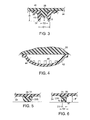
FIG. 3 is a section view of a portion of the sole assembly ofFIG. 1 . -
FIG. 4 is a section view of a portion of the sole assembly ofFIG. 1 , taken along section line 4-4. -
FIG. 5 is a section view of a secondary cleat of the sole assembly ofFIG. 1 . -
FIG. 6 is a section view of an alternative embodiment of a secondary cleat of the sole assembly ofFIG. 1 . -
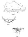
FIG. 7 is an elevation view of an alternative embodiment of an article of footwear with a cleated sole assembly. -
FIG. 8 isFIG. 4 is a section view of an alternative embodiment of a portion of the sole assembly ofFIG. 1 . -
FIG. 9 is a section view of an alternative embodiment of a portion of the sole assembly ofFIG. 1 . - The figures referred to above are not drawn necessarily to scale, should be understood to provide a representation of particular embodiments of the invention, and are merely conceptual in nature and illustrative of the principles involved. Some features of the article of footwear with a cleated sole assembly depicted in the drawings have been enlarged or distorted relative to others to facilitate explanation and understanding. The same reference numbers are used in the drawings for similar or identical components and features shown in various alternative embodiments. Articles of footwear with a cleated sole assembly as disclosed herein would have configurations and components determined, in part, by the intended application and environment in which they are used.
- The following discussion and accompanying figures disclose various embodiments of an article of footwear with a cleated sole assembly, which is particularly suited for use on artificial turf surfaces. It is to be appreciated that the article of footwear may also be used on natural turf surfaces.
- An article of
footwear 10 is depicted inFIGS. 1-2 as including an upper 12 and a cleatedsole assembly 14. For reference purposes,footwear 10 may be divided into three general portions: atoe portion 16, aforefoot portion 17, amidfoot portion 18, and aheel portion 20, as shown inFigures 1 and 2 . Footwear 10 also includes alateral side 22 and amedial side 24.Toe portion 16 generally includes portions offootwear 10 corresponding with the toes.Forefoot portion 17 generally includes the joints connecting the metatarsals with the phalanges.Midfoot portion 18 generally includes portions offootwear 10 corresponding with the arch area of the foot, andheel portion 20 corresponds with rear portions of the foot, including the calcaneus bone.Lateral side 22 andmedial side 24 extend through each of portions 16-20 and correspond with opposite sides offootwear 10. - Portions 16-20 and sides 22-24 are not intended to demarcate precise areas of
footwear 10. Rather, portions 16-20 and sides 22-24 are intended to represent general areas offootwear 10 to aid in the following discussion. In addition tofootwear 10, portions 16-20 and sides 22-24 may also be applied to upper 12,sole assembly 14, and individual elements thereof. - The figures illustrate only the article of footwear intended for use on the left foot of a wearer. One skilled in the art will recognize that a right article of footwear, such article being the mirror image of the left, is intended to fall within the scope of the present invention.
- Unless otherwise stated, or otherwise clear from the context below, directional terms used herein, such as rearwardly, forwardly, inwardly, downwardly, upwardly, etc., refer to directions relative to
footwear 10 itself.Footwear 10 is shown inFIG. 1 to be disposed substantially horizontally, as it would be positioned on a horizontal surface when worn by a wearer. However, it is to be appreciated thatfootwear 10 need not be limited to such an orientation. Thus, in the illustrated embodiment ofFIG. 1 , rearwardly is towardheel portion 20, that is, to the left as seen inFIG. 1 . Naturally, forwardly is towardtoe portion 16, that is, to the right seen inFIG. 1 , and downwardly is toward the bottom of the page as seen inFIG. 1 . Inwardly is toward the center offootwear 10, and outwardly is toward the outer peripheral edge offootwear 10. -
Upper 12 forms an interior void that comfortably receives a foot and secures the position of the foot relative tosole assembly 14. The configuration of upper 12, as depicted, is suitable for use during athletic activities that involve running. Accordingly, upper 12 may have a lightweight, breathable construction that includes multiple layers of leather, textile, polymer, and foam elements adhesively bonded and stitched together. For example, upper 12 may have an exterior that includes leather elements and textile elements for resisting abrasion and providing breathability, respectively. The interior of upper 12 may have foam elements for enhancing the comfort offootwear 10, and the interior surface may include a moisture-wicking textile for removing excess moisture from the area immediately surrounding the foot. -
Sole assembly 14 may be secured to upper 12 by an adhesive, or any other suitable fastening means.Sole assembly 14, which is generally disposed between the foot of the wearer and the ground, provides attenuation of ground reaction forces (i.e., imparting cushioning), traction, and may control foot motions, such as pronation. As with conventional articles of footwear,sole assembly 14 includes an insole (not shown) located within upper 12, and anoutsole 28.Outsole 28 includes a plurality of cleats, described in detail below. - In certain embodiments, as seen in
Fig. 7 , sole assembly may include amidsole 26.Midsole 26 is attached to upper 12 and functions as a shock-attenuating and energy-absorbing component offootwear 10. -
Sole assembly 14 includes asole plate 30 positioned beneath upper 12. In certain embodiments,sole plate 30 is formed of thermoplastic polyurethane (TPU). In other embodiments,sole plate 30 may be formed of a glass-filled nylon material. In still other embodiments,sole plate 30 may be formed of a glass-filled TPU. Other suitable materials forsole plate 30 will become readily apparent to those skilled in the art, given the benefit of this disclosure. - As noted above,
outsole 28 includes a plurality ofcleats 32 extending downwardly from alower surface 34 ofsole plate 30 and about a periphery ofsole plate 30. Eachcleat 32 has acentral recess 36 formed therein such thatcleats 32 are substantially hollow cylindrical members.Cleats 32 have a height H, measured fromlower surface 34 to the lowermost portion ofcleat 32, and an outer diameter D1.Recess 36 has an inner diameter D2, and a depth R. It is to be appreciated that each of height H, diameters D1 and D2, and depth R are parameters that can be altered to provide desired aesthetic and performance characteristics forfootwear 10. For example, these parameters can be adjusted to be optimized for a particular playing surface upon whichfootwear 10 will be used. Alternatively, these parameters can be altered depending on the particular sport to be played. These parameters can be varied from one article offootwear 10 to another, or they may be varied betweendifferent cleats 32 on the same article of footwear. In certain embodiments, two ormore cleats 32 and correspondingrecesses 36 on article offootwear 10 could have the same height H, diameters D 1 and D2, and depth R as one another, while one ormore cleats 32 and correspondingrecesses 36 could have at least one of height H, diameters D1 and D2, and depth R that are different than that of the two ormore cleats 32 and correspondingrecesses 36 with the same parameters. It is to be appreciated that any number of similar or different parameters can apply to any ofcleats 32 and correspondingrecesses 36 onfootwear 10. - In certain embodiments, depth R of
cleats 32 is approximately 5 mm. As noted above,cleats 32 may have any desired depth. In certain embodiments, diameter D1 is approximately 12.5 mm and diameter D2 is approximately 6.5 mm, such that the wall thickness ofcleats 32 is approximately 3.0 mm at its lower surface. It is to be appreciated that diameters D1 and D2 may have any desired value. - In the illustrated embodiment, as seen in
FIG. 2 , there are fourrear cleats 32R positioned inheel portion 20 ofsole assembly 14. Two of therear cleats 32R are positioned onlateral side 22 ofsole assembly 14, and the other tworear cleats 32R are positioned onmedial side 24. In the illustrated embodiment,rear cleats 32R have a height H of approximately 14 mm. - In the illustrated embodiment, there are four
forefoot cleats 32F positioned inforefoot portion 17 ofsole assembly 14. Twoforefoot cleats 32F are positioned onlateral side 22, and twoforefoot cleats 32F are positioned onmedial side 24. In certain embodiments,forefoot cleats 32F have a height of approximately 11 mm. - In certain embodiments, a plurality of secondary cleats 33 is provided on
sole assembly 14. Secondary cleats 33 are provided inboard ofcleats 32. Somesecondary cleats 33S are solid and do not include a recess as found incleats 32. Somesecondary cleats 33R include a recess in a lower surface thereof. - In the illustrated embodiment, two forefoot
secondary cleats 33S are positioned in a central area offorefoot portion 17, with arib 39 extending along the lower surface of upper 12 between thesecondary cleats 33S. In the illustrated embodiment, the forefootsecondary cleats 33S are positioned forward and rearward of one another such that therib 39 that extends between them is substantially parallel to longitudinal axis L. - In the illustrated embodiment, a plurality of toe
secondary cleats 33S is positioned in a central area oftoe portion 16. In the illustrated embodiment, threesecondary cleats 33S are positioned intoe portion 16, with two rearmostsecondary cleats 33S positioned behind a foremostsecondary cleat 33S in a triangular configuration. Arib 39 extends between the foremostsecondary cleat 33S and each of the rearmostsecondary cleats 33S. - As noted above, and more clearly seen in
FIG. 5 ,secondary cleats 33S are solid. In certain embodiments, arecess 31 is formed in an upper surface of eachsecondary cleat 33S, with aprojection 35 onlower surface 34 ofsole plate 32 extending intorecess 31. In certain embodiments,secondary cleats 33S may have a height of approximately 6.5 mm and an outer diameter at their lowermost surface of approximately 9.0 mm. -
Secondary cleats 33R are positioned inmidfoot portion 17 inboard ofmedial forefoot cleats 32F. As noted above, and seen inFIG. 6 ,secondary cleats 33R include arecess 37 in a lower surface thereof.Secondary cleats 33R have an inner diameter D3 of approximately 4.0 mm and an outer diameter D4 of approximately 8.0 mm such that the wall thickness ofsecondary cleats 33R at their lower most surface is approximately 2.0 mm.Secondary cleats 33R have a height P of approximately 5.5 mm, andrecess 37 has a depth N of approximately 1.0 mm. - In the illustrated embodiment, six
toe cleats 32T are positioned intoe portion 16 ofsole assembly 14. Threetoe cleats 32T are positioned alonglateral side 22, while the other threetoe cleats 32T are positioned alongmedial side 24. In certain embodiments, the height H oftoe cleats 32T decrease in size alonglateral side 22 andmedial side 24. For example, in certain embodiments, therearmost toe cleats 32T have a height H of approximately 9 mm, thecentral toe cleats 32T have a height H of approximately 8 mm, and thefrontmost toe cleats 32T have a height H of approximately 7 mm. Thus, thetoe cleats 32T have heights that vary from approximately 7 mm in a foremost portion oftoe portion 16 to approximately 9 mm in a rearmost portion oftoe portion 16. - Thus, in the embodiment illustrated in
FIG. 2 , the height H ofcleats 32 generally decreases fromheel portion 20 totoe portion 16. This provides for greater anchoring for the user's heel, and more flexibility and pivoting capability for the ball and toes of the user's foot. - As seen in
FIG. 3 ,cleats 32 have a core 38 formed of a first material having a first hardness level, and anouter layer 40 positioned oncore 38 and formed of a second material having a second hardness level that is lower than the first hardness level, that is softer than the first material. Thus, the second material has a lower hardness value than that of the first material. Providingouter layer 40 ofcleats 32 with a softer material can provide enhanced cushioning for the feet of the user, which is especially advantageous whenfootwear 10 is used on harder surfaces, such as artificial turf surfaces. -
Outer layer 40 has a thickness T that varies throughoutcleat 32. The thickness ofouter layer 40 can be adjusted to provide different performance characteristics forsole assembly 14. - In certain embodiments,
core 38 of eachcleat 32 is of unitary, that is, one-piece construction withsole plate 30. Thus,core 38 may be formed of TPU, glass-filled nylon, or glass-filled TPU, for example. In certain embodiments, the first hardness level of the first material used to formcore 38 may be between approximately 90A and approximately 98A. It is to be appreciated thatcore 38 may be a separate element secured tosole plate 30 with suitable fastening means, such as adhesive, for example. - In certain embodiments,
outer layer 40 may be formed of a TPU, for example. Other suitable materials forouter layer 40 will become readily apparent to those skilled in the art, given the benefit of this disclosure. As noted above,outer layer 40 has a hardness level that is lower than that ofcore 38. In certain embodiments, the second hardness level of the second material used to formouter layer 40 may be between approximately 60A and approximately 80A. In certain embodiments, outer layer has a hardness level of approximately 70A.Outer layer 40 also advantageously provides improved abrasion resistance forfootwear 10. - In the embodiment illustrated in
FIG. 3 ,outer layer 40 has a substantially smooth surface. In certain embodiments, as seen inFIG. 9 ,outer layer 40 may have a textured outer surface. A non-smooth textured surface can improve traction forfootwear 10. It is to be appreciated thatcertain cleats 32 may have a textured outer surface whileother cleats 32 have a non-textured smooth outer surface. It is also to be appreciated that the textured surface can be irregular, or random, while in other embodiments the texture onouter layer 40 may be formed in patter. Thus, for example, a pattern or dimples or ridges could be provided onouter layer 40. - In certain embodiments, one or more ridges or
ribs 39 may extend alonglower surface 34 ofsole plate 30.Ribs 39 extend between a corresponding pair ofcleats 32. As illustrated inFIG. 2 ,ribs 39 extend between theadjacent forefoot cleats 32F onlateral side 24 oftoe portion 16. Similarly, arib 39 extends between theforefoot cleats 32F onlateral side 24. Further,ribs 39 extend between therearmost midfoot cleat 32F and the foremostrear cleat 32R on bothlateral side 24 andmedial side 22 ofsole assembly 14. Additionally, arib 39 extends between therear cleats 32R on bothlateral side 24 andmedial side 22 ofheel portion 20. - In certain embodiments,
cleats 32 may include abase portion 41 positioned onlower surface 34. In the embodiment illustrated inFIG. 2 , abase portion 41 supports forefootcleats 32F onmedial side 22 oftoe portion 16. Abase portion 41 also supportforefoot cleats 32F onmedial side 22 ofmidfoot portion 18 and extends inwardly beneathforefoot cleats 32R. - In certain embodiments, a
circulation plate 42 is provided onlower surface 34 ofsole plate 30, as seen inFIGS. 1 and4 . In the illustratedembodiment circulation plate 42 extends from a central portion ofheel portion 20 to a rear portion ofmidfoot portion 18.Circulation plate 42 andsole plate 30 define acirculation cavity 44 therebetween, thereby providing circulation and cooling beneathsole plate 30. In this embodiment,circulation cavity 44 extends betweencirculation plate 42 andsole plate 30. In the illustratedembodiment circulation plate 42 is curved laterally across a longitudinal axis L ofsole plate 30 so as to be convex with respect tosole plate 30. It is to be appreciated that in otherembodiments circulation cavity 44 could be partly defined by a recess inlower surface 34 ofsole plate 30. - Another embodiment is shown in
FIG. 8 , in whichcirculation cavity 44 is positioned below a lasting board/stroebel sock element 43, thereby allowing air to pass into the interior offootwear 10. - In certain embodiments,
sole plate 30,cleats 32, andcirculation plate 42 are formed by injection molding. In certain embodiments,outer layer 40 ofcleats 32 is injected first using the second material, followed by a second injection of the first material onouter layer 40 to formsole plate 30 andcore 38. Finally a third material to formcirculation plate 42 is injected ontosole plate 30. It is to be appreciated that, in other embodiments,circulation plate 42 could be secured tosole plate 30 with suitable fastening means such as adhesive. In other embodiments,sole plate 30 andcore 38 could be formed beforeouter layer 40 ofcleats 32. Other suitable methods and orders of formingsole plate 30,cleats 32, andcirculation plate 42 will become readily apparent to those skilled in the art, given the benefit of this disclosure. - A plurality of
apertures 46 is formed incirculation plate 42 to provide for air flow throughcirculation cavity 44. Allowing air to flow throughcirculation cavity 44 provides cooling forsole plate 30 and, therefore, all offootwear 10, whilesole plate 30 provides a barrier between the user's foot and the exterior offootwear 10. In certain embodiments, a first plurality of apertures 46a is formed at afront portion 48 ofcirculation plate 42, and a second plurality of apertures 46b is formed at arear portion 50 ofcirculation plate 42. In the illustrated embodiment, eachaperture 46 is a substantially longitudinal slot formed incirculation plate 42, with a longitudinal axis S that extends substantially parallel to longitudinal axis L ofsole plate 30. -
Circulation plate 42 may be formed of a glass-filled nylon or a glass-filled TPU, for example. In addition to providing air circulation and cooling,circulation plate 42 can also provide structure tosole assembly 10, thereby enhancing support for the user's foot. - Thus, while there have been shown, described, and pointed out fundamental novel features of various embodiments, it will be understood that various omissions, substitutions, and changes in the form and details of the devices illustrated, and in their operation, may be made by those skilled in the art without departing from the spirit and scope of the device described herein. For example, it is expressly intended that all combinations of those elements and/or steps which perform substantially the same function, in substantially the same way, to achieve the same results are within the scope of the invention. Substitutions of elements from one described embodiment to another are also fully intended and contemplated. It is the intention, therefore, to be limited only as indicated by the scope of the claims appended hereto.
Claims (13)
- An article of footwear comprising:an upper; anda sole assembly secured to the upper and comprising:a sole plate having a lower surface;a plurality of cleats extending downwardly from the lower surface, each cleat having a central recess formed therein, a core formed of a first material, and an outer layer on the core and formed of a second material that is softer than the first material; andcharacterised in that the sole assembly further comprisesa circulation plate disposed on the lower surface of the sole plate and defining a circulation cavity between the sole plate and the circulation plate, a first plurality of apertures extending through a front portion of the circulation plate, and a second plurality of apertures extending through a rear portion of the circulation plate.
- The article of footwear of claim 1, wherein the first material is one of TPU and glass-filled nylon.
- The article of footwear of claim 1, wherein the second material is TPU.
- The article of footwear of claim 1, wherein the circulation plate extends from a heel portion of the sole plate to a midfoot portion of the sole plate.
- The article of footwear of claim 1, wherein each of the first plurality of apertures and the second plurality of apertures comprises a slot having a longitudinal axis that is substantially parallel to a longitudinal axis of the sole plate.
- The article of footwear of claim 1, wherein:(1) the sole plate is formed of one of glass-filled nylon and TPU; and/or(2) the sole plate is formed of a heat blocking material.
- The article of footwear of claim 1, wherein at least some of the cleats are positioned proximate a peripheral edge of the sole plate.
- The article of footwear of claim 1, wherein the outer layer of at least one cleat has a textured outer surface.
- The article of footwear of claim 1 or claim 4, further comprising a first set of cleats in a forefoot portion of having a height ranging from approximately 7 mm in a foremost portion of the forefoot portion to approximately 9 mm in a rearmost portion of the forefoot portion.
- The article of footwear of claim 9, further comprising a second set of cleats in a midfoot portion of the sole plate and having a height of approximately 11 mm.
- The article of footwear of claim 10, further comprising a second set of cleats in a midfoot portion of the sole plate and having a height of approximately 11 mm.
- The article of footwear of claim 1 or claim 4, wherein the hardness of the first material is between approximately 90A and approximately 98A.
- The article of footwear of claim 1 or claim 4, wherein the hardness of the second material is between approximately 60A and approximately 80A.
Priority Applications (1)
| Application Number | Priority Date | Filing Date | Title |
|---|---|---|---|
| EP15186086.3A EP3011852B1 (en) | 2008-05-30 | 2009-05-22 | Article of footwear with cleated sole assembly |
Applications Claiming Priority (2)
| Application Number | Priority Date | Filing Date | Title |
|---|---|---|---|
| US12/130,097 US8056267B2 (en) | 2008-05-30 | 2008-05-30 | Article of footwear with cleated sole assembly |
| PCT/US2009/044933 WO2009148853A1 (en) | 2008-05-30 | 2009-05-22 | Article of footwear with cleated sole assembly |
Related Child Applications (2)
| Application Number | Title | Priority Date | Filing Date |
|---|---|---|---|
| EP15186086.3A Division EP3011852B1 (en) | 2008-05-30 | 2009-05-22 | Article of footwear with cleated sole assembly |
| EP15186086.3A Division-Into EP3011852B1 (en) | 2008-05-30 | 2009-05-22 | Article of footwear with cleated sole assembly |
Publications (2)
| Publication Number | Publication Date |
|---|---|
| EP2280620A1 EP2280620A1 (en) | 2011-02-09 |
| EP2280620B1 true EP2280620B1 (en) | 2015-11-11 |
Family
ID=41149134
Family Applications (2)
| Application Number | Title | Priority Date | Filing Date |
|---|---|---|---|
| EP09759014.5A Active EP2280620B1 (en) | 2008-05-30 | 2009-05-22 | Article of footwear with cleated sole assembly |
| EP15186086.3A Active EP3011852B1 (en) | 2008-05-30 | 2009-05-22 | Article of footwear with cleated sole assembly |
Family Applications After (1)
| Application Number | Title | Priority Date | Filing Date |
|---|---|---|---|
| EP15186086.3A Active EP3011852B1 (en) | 2008-05-30 | 2009-05-22 | Article of footwear with cleated sole assembly |
Country Status (3)
| Country | Link |
|---|---|
| US (1) | US8056267B2 (en) |
| EP (2) | EP2280620B1 (en) |
| WO (1) | WO2009148853A1 (en) |
Families Citing this family (55)
| Publication number | Priority date | Publication date | Assignee | Title |
|---|---|---|---|---|
| US8616892B2 (en) | 2009-04-02 | 2013-12-31 | Nike, Inc. | Training system for an article of footwear with a traction system |
| EP2413730B1 (en) | 2009-04-02 | 2018-05-23 | NIKE Innovate C.V. | Traction elements |
| US8632342B2 (en) | 2009-05-28 | 2014-01-21 | Nike, Inc. | Training system for an article of footwear |
| US8573981B2 (en) | 2009-05-29 | 2013-11-05 | Nike, Inc. | Training system for an article of footwear with a ball control portion |
| US8453354B2 (en) | 2009-10-01 | 2013-06-04 | Nike, Inc. | Rigid cantilevered stud |
| ITFI20100010A1 (en) * | 2010-01-22 | 2011-07-23 | Leonardo Mariotti | SPORTS FOOTWEAR |
| FR2955466B1 (en) * | 2010-01-25 | 2012-04-20 | Salomon Sas | IMPROVED SHOE SHOE |
| US8533979B2 (en) | 2010-02-18 | 2013-09-17 | Nike, Inc. | Self-adjusting studs |
| US8375604B2 (en) * | 2010-04-07 | 2013-02-19 | Nike, Inc. | Article of footwear with multiple cleat systems |
| US8322049B2 (en) | 2010-07-30 | 2012-12-04 | Nike, Inc. | Wear-resistant outsole |
| DE102010044816A1 (en) * | 2010-09-09 | 2012-03-15 | Fa. Mayer Gbr (Vertretungsberechtigte Gesellschafter: Herr Helmut Mayer, 88045 Friedrichshafen) | Sports shoe or work shoe, has sheets forming connecting projection or clamping projection or threaded projection, which is aligned downwardly and projected from outsole, where projections are attached on replaceable cleats or spikes |
| DE102010040964B4 (en) * | 2010-09-17 | 2019-10-24 | Adidas Ag | Studs for studded shoe |
| US8529267B2 (en) | 2010-11-01 | 2013-09-10 | Nike, Inc. | Integrated training system for articles of footwear |
| US8713819B2 (en) | 2011-01-19 | 2014-05-06 | Nike, Inc. | Composite sole structure |
| US8418382B2 (en) | 2011-03-16 | 2013-04-16 | Nike, Inc. | Sole structure and article of footwear including same |
| EP2499928A1 (en) * | 2011-03-18 | 2012-09-19 | P-Sports GmbH | Sporting shoe with a sole having a number of studs |
| US9138027B2 (en) * | 2011-09-16 | 2015-09-22 | Nike, Inc. | Spacing for footwear ground-engaging member support features |
| US9220320B2 (en) | 2011-09-16 | 2015-12-29 | Nike, Inc. | Sole arrangement with ground-engaging member support features |
| US8806779B2 (en) * | 2011-09-16 | 2014-08-19 | Nike, Inc. | Shaped support features for footwear ground-engaging members |
| US8966787B2 (en) | 2011-09-16 | 2015-03-03 | Nike, Inc. | Orientations for footwear ground-engaging member support features |
| US8984774B2 (en) * | 2011-09-16 | 2015-03-24 | Nike, Inc. | Cut step traction element arrangement for an article of footwear |
| US20130067765A1 (en) * | 2011-09-16 | 2013-03-21 | Nike, Inc. | Article Of Footwear |
| US9101178B2 (en) * | 2011-11-23 | 2015-08-11 | Nike, Inc. | Article of footwear with a lateral offset heel stud |
| US20130255102A1 (en) * | 2012-04-02 | 2013-10-03 | Rayford Terrell | Supplemental removable stick on cleat for footwear |
| US9615621B2 (en) * | 2012-06-04 | 2017-04-11 | Nike, Inc. | Sole structure with integrated cleat member and methods of making |
| US9314065B2 (en) * | 2012-06-15 | 2016-04-19 | Nike, Inc. | Article of footwear with base plate having structure and studs |
| US8973290B2 (en) * | 2012-07-30 | 2015-03-10 | Nike, Inc. | Reinforcing shank arrangement for footwear sole structure |
| US9609915B2 (en) | 2013-02-04 | 2017-04-04 | Nike, Inc. | Outsole of a footwear article, having fin traction elements |
| WO2015073629A1 (en) * | 2013-11-15 | 2015-05-21 | Nike Innovate C.V. | Article of footwear with self-cleaning cleats |
| US10028551B2 (en) * | 2014-04-24 | 2018-07-24 | Nike, Inc. | Interchangeable chassis for cleated footwear |
| US9930934B2 (en) * | 2014-07-03 | 2018-04-03 | Nike, Inc. | Article of footwear with a segmented plate |
| WO2016162967A1 (en) * | 2015-04-08 | 2016-10-13 | 株式会社アシックス | Spike sole and shoe bottom |
| US10448703B2 (en) | 2015-04-08 | 2019-10-22 | Nike, Inc. | Footwear sole structure with compliant membrane |
| EP3285608B1 (en) | 2015-04-24 | 2019-05-22 | Nike Innovate C.V. | Footwear sole structure having bladder with integrated outsole |
| WO2017035586A1 (en) * | 2015-08-31 | 2017-03-09 | Schumann Ronald Frederick | Shoe sole |
| WO2017048937A1 (en) * | 2015-09-18 | 2017-03-23 | Nike Innovate C.V. | Footwear sole structure with nonlinear bending stiffness |
| US20170224053A1 (en) * | 2016-02-05 | 2017-08-10 | Ecco Sko A/S | Outer sole for spikeless footwear |
| USD849384S1 (en) * | 2017-06-14 | 2019-05-28 | Under Armour, Inc. | Shoe sole |
| US11039659B2 (en) * | 2017-09-07 | 2021-06-22 | Nike, Inc. | Sole structure for article of footwear |
| CN109551703B (en) * | 2017-09-26 | 2020-11-10 | 加久企业股份有限公司 | Foaming sole forming method and mould and sole structure thereof |
| KR102643930B1 (en) | 2018-05-30 | 2024-03-05 | 나이키 이노베이트 씨.브이. | Footwear sole structure with bladder |
| JP2020141737A (en) * | 2019-03-04 | 2020-09-10 | 美津濃株式会社 | Outsole structure, its manufacturing method, and cleats shoes using the outsole structure |
| USD899737S1 (en) * | 2019-06-11 | 2020-10-27 | Nike, Inc. | Shoe |
| USD889106S1 (en) * | 2019-06-11 | 2020-07-07 | Nike, Inc. | Shoe |
| USD889105S1 (en) * | 2019-06-11 | 2020-07-07 | Nike, Inc. | Shoe |
| USD899738S1 (en) * | 2019-06-11 | 2020-10-27 | Nike, Inc. | Shoe |
| CN110638138A (en) * | 2019-11-06 | 2020-01-03 | 厦门凡瑞德体育用品有限公司 | Sole with shoe nail |
| US12295451B2 (en) * | 2020-11-05 | 2025-05-13 | Fuerst Group, Inc. | Article of footwear with heel cushion |
| JP7828791B2 (en) * | 2022-03-10 | 2026-03-12 | 美津濃株式会社 | Outsole studs, outsoles for cleat shoes, method for manufacturing outsoles, and cleat shoes |
| USD1012458S1 (en) * | 2023-02-23 | 2024-01-30 | Nike, Inc. | Shoe |
| USD1003026S1 (en) * | 2023-02-23 | 2023-10-31 | Nike, Inc. | Shoe |
| USD1002169S1 (en) * | 2023-02-23 | 2023-10-24 | Nike, Inc. | Shoe |
| US20240285034A1 (en) * | 2023-02-28 | 2024-08-29 | Nike, Inc. | Article of footwear having a sole structure |
| US12507757B2 (en) * | 2023-04-12 | 2025-12-30 | Acushnet Company | Golf shoe with traction elements |
| US20260041197A1 (en) * | 2024-08-06 | 2026-02-12 | Nike, Inc. | Sole structure for article of footwear |
Citations (16)
| Publication number | Priority date | Publication date | Assignee | Title |
|---|---|---|---|---|
| US3913243A (en) | 1975-02-20 | 1975-10-21 | Lawrence Peska Ass Inc | Golf sandal |
| FR2621227A1 (en) | 1987-10-02 | 1989-04-07 | Giraudet Bernard | Walking support for a sports shoe, for example a golf shoe |
| GB2256784A (en) | 1991-06-19 | 1992-12-23 | Uhl Sportartikel Karl | Sole and sports shoe |
| US5377431A (en) | 1993-06-15 | 1995-01-03 | Walker; Andrew S. | Directionally yieldable cleat assembly |
| US5473827A (en) | 1991-09-19 | 1995-12-12 | Patrick International | Outsole for sports shoes |
| US5666746A (en) | 1993-12-23 | 1997-09-16 | Pollard; Owen Craig | Spiked shoe protector with adjustable strap to accommodate different shoe sizes |
| US5996260A (en) | 1998-10-26 | 1999-12-07 | Macneill Engineering Company, Inc. | Dual density plastic cleat for footwear |
| US6138386A (en) | 1997-09-03 | 2000-10-31 | Spalding Sports Worldwide, Inc. | Composite cleat for athletic shoe |
| CA2307942A1 (en) | 2000-05-09 | 2001-11-09 | Nathan M. Korman | Boot binding system for a snowboard |
| US6374518B2 (en) | 1998-01-21 | 2002-04-23 | Tubbs Snowshoe Company Llc | Terrain-engaging cleat for traction enhancement |
| US6434860B1 (en) | 1998-09-25 | 2002-08-20 | Sun Standard, Inc. | Removably mountable cleat |
| US6554295B2 (en) | 2000-04-03 | 2003-04-29 | K-2 Corporation | Strapless toelock binding for snowboards |
| US20040020075A1 (en) * | 2002-08-01 | 2004-02-05 | Louis Garneau Sport Inc. | Bicycle shoe with ventilating sole |
| US6742800B2 (en) | 2001-04-18 | 2004-06-01 | Shimano, Inc. | Snowboard binding system |
| US20060168847A1 (en) * | 2005-01-31 | 2006-08-03 | Nike, Inc. | Breathable sole structures and products containing such sole structures |
| WO2009117543A1 (en) | 2008-03-20 | 2009-09-24 | Nike International Ltd. | Cleat member for article of footwear |
Family Cites Families (37)
| Publication number | Priority date | Publication date | Assignee | Title |
|---|---|---|---|---|
| US911479A (en) | 1908-06-02 | 1909-02-02 | Flexible Rubber Goods Company | Antislipping shoe-sole. |
| US989514A (en) | 1909-11-08 | 1911-04-11 | Flexible Rubber Goods Company | Suction-tread. |
| US1141227A (en) | 1914-11-02 | 1915-06-01 | Goodyear Tire & Rubber | Rubber heel. |
| US3494055A (en) | 1968-07-25 | 1970-02-10 | Willard Bradford Mcsorley | Non-slip shoe |
| US3988840A (en) | 1975-05-07 | 1976-11-02 | Hyde Athletic Industries, Inc. | Sole construction |
| US4014114A (en) | 1975-11-28 | 1977-03-29 | Three Line Research & Development Co., Inc. | Spike cluster |
| US4167071A (en) | 1977-09-12 | 1979-09-11 | Herbert Koransky | Golf shoe |
| US4173083A (en) * | 1978-01-16 | 1979-11-06 | Riddell, Inc. | Athletic shoe construction |
| DE2904471A1 (en) | 1979-02-07 | 1980-08-21 | Adidas Sportschuhe | OUTSOLE FOR SPORTSHOES, ESPECIALLY FOR USE ON ARTIFICIAL GRASS |
| US4319412A (en) | 1979-10-03 | 1982-03-16 | Pony International, Inc. | Shoe having fluid pressure supporting means |
| US4327503A (en) | 1980-01-17 | 1982-05-04 | Brs, Inc. | Outer sole structure for athletic shoe |
| US4524531A (en) | 1982-12-02 | 1985-06-25 | Vanderipe Donald R | Golf shoes |
| US4466205A (en) * | 1983-01-10 | 1984-08-21 | Corbari George V | Safety stud |
| DE3660702D1 (en) * | 1985-07-27 | 1988-10-20 | Adidas Sportschuhe | Stud for a sports shoe |
| DE3603127C1 (en) * | 1986-02-01 | 1987-06-25 | Adidas Sportschuhe | Ceramic gripping element for sports shoes |
| DE3706068A1 (en) * | 1987-02-25 | 1988-09-08 | Dassler Puma Sportschuh | GRIP ELEMENT FOR SPORTSHOES |
| US4769931A (en) | 1987-08-06 | 1988-09-13 | Morrow Donald W | Cleated sole for footwear |
| US4875683A (en) | 1988-07-12 | 1989-10-24 | Wellman Edward F | Golf club swing improvement apparatus |
| US5617653A (en) * | 1991-04-15 | 1997-04-08 | Andrew S. Walker | Break-away cleat assembly for athletic shoe |
| US5461801A (en) * | 1993-08-18 | 1995-10-31 | Anderton; Graeme | Cleated athletic shoe with crisscross arch reinforcement |
| US5410823A (en) | 1994-01-26 | 1995-05-02 | Iyoob; Simon J. | Replaceable golf cleat |
| DE4417563A1 (en) | 1994-05-19 | 1995-11-23 | Uhl Sportartikel Karl | Football boot with additional grips on sole |
| US5901473A (en) * | 1995-10-10 | 1999-05-11 | Heifort, Iv; Ernest August | Method for converting a game shoe to a weighted training shoe |
| US5761832A (en) * | 1996-04-18 | 1998-06-09 | George; Gary F. | Athletic shoe having radially extending ribs |
| US5901472A (en) | 1996-08-01 | 1999-05-11 | Diversified Industrial Technology, Inc. | Athletic shoe system and removable cleat |
| US5853844A (en) | 1997-05-23 | 1998-12-29 | Wen; Keith | Rubber pad construction with resilient protrusions |
| US5906059A (en) * | 1997-09-03 | 1999-05-25 | Lisco, Inc. | Composite cleat for athletic shoe |
| US6381878B1 (en) * | 1997-09-03 | 2002-05-07 | Spalding Sports Worldwide, Inc. | Composite cleat for athletic shoe |
| US6023860A (en) | 1997-12-11 | 2000-02-15 | Softspikes, Inc. | Athletic shoe cleat |
| US6543160B2 (en) | 2001-04-05 | 2003-04-08 | Price Advanced Innovations, Inc. | Athletic shoe attachment |
| US6968637B1 (en) | 2002-03-06 | 2005-11-29 | Nike, Inc. | Sole-mounted footwear stability system |
| ITPN20030018A1 (en) | 2003-03-04 | 2004-09-05 | Gilda Design Di Vania Cadamuro | DAMPING ELEMENT WITH CORRUGATED CONFORMATION. |
| US6973745B2 (en) | 2003-11-06 | 2005-12-13 | Elan-Polo, Inc. | Athletic shoe having an improved cleat arrangement |
| ES2257954B1 (en) | 2005-01-14 | 2007-04-16 | Calzados Anatomicos Calana, S.L. | NON-SLIDING AND SHOCK ABSORBER ELEMENT FOR FOOTWEAR FLOORS AND THE CORRESPONDING FOOTWEAR FLOOR INCLUDING SUCH ELEMENT. |
| US7594345B2 (en) | 2005-10-12 | 2009-09-29 | Nike, Inc. | Article of footwear having sole with ribbed structure |
| WO2007143443A1 (en) * | 2006-05-30 | 2007-12-13 | Cleats Llc | Removable footwear cleat with cushioning |
| US7827705B2 (en) * | 2007-03-08 | 2010-11-09 | Nike, Inc. | Article of footwear with multiple cleat sizes |
-
2008
- 2008-05-30 US US12/130,097 patent/US8056267B2/en active Active
-
2009
- 2009-05-22 WO PCT/US2009/044933 patent/WO2009148853A1/en not_active Ceased
- 2009-05-22 EP EP09759014.5A patent/EP2280620B1/en active Active
- 2009-05-22 EP EP15186086.3A patent/EP3011852B1/en active Active
Patent Citations (16)
| Publication number | Priority date | Publication date | Assignee | Title |
|---|---|---|---|---|
| US3913243A (en) | 1975-02-20 | 1975-10-21 | Lawrence Peska Ass Inc | Golf sandal |
| FR2621227A1 (en) | 1987-10-02 | 1989-04-07 | Giraudet Bernard | Walking support for a sports shoe, for example a golf shoe |
| GB2256784A (en) | 1991-06-19 | 1992-12-23 | Uhl Sportartikel Karl | Sole and sports shoe |
| US5473827A (en) | 1991-09-19 | 1995-12-12 | Patrick International | Outsole for sports shoes |
| US5377431A (en) | 1993-06-15 | 1995-01-03 | Walker; Andrew S. | Directionally yieldable cleat assembly |
| US5666746A (en) | 1993-12-23 | 1997-09-16 | Pollard; Owen Craig | Spiked shoe protector with adjustable strap to accommodate different shoe sizes |
| US6138386A (en) | 1997-09-03 | 2000-10-31 | Spalding Sports Worldwide, Inc. | Composite cleat for athletic shoe |
| US6374518B2 (en) | 1998-01-21 | 2002-04-23 | Tubbs Snowshoe Company Llc | Terrain-engaging cleat for traction enhancement |
| US6434860B1 (en) | 1998-09-25 | 2002-08-20 | Sun Standard, Inc. | Removably mountable cleat |
| US5996260A (en) | 1998-10-26 | 1999-12-07 | Macneill Engineering Company, Inc. | Dual density plastic cleat for footwear |
| US6554295B2 (en) | 2000-04-03 | 2003-04-29 | K-2 Corporation | Strapless toelock binding for snowboards |
| CA2307942A1 (en) | 2000-05-09 | 2001-11-09 | Nathan M. Korman | Boot binding system for a snowboard |
| US6742800B2 (en) | 2001-04-18 | 2004-06-01 | Shimano, Inc. | Snowboard binding system |
| US20040020075A1 (en) * | 2002-08-01 | 2004-02-05 | Louis Garneau Sport Inc. | Bicycle shoe with ventilating sole |
| US20060168847A1 (en) * | 2005-01-31 | 2006-08-03 | Nike, Inc. | Breathable sole structures and products containing such sole structures |
| WO2009117543A1 (en) | 2008-03-20 | 2009-09-24 | Nike International Ltd. | Cleat member for article of footwear |
Also Published As
| Publication number | Publication date |
|---|---|
| EP2280620A1 (en) | 2011-02-09 |
| EP3011852A1 (en) | 2016-04-27 |
| US8056267B2 (en) | 2011-11-15 |
| US20090293315A1 (en) | 2009-12-03 |
| EP3011852B1 (en) | 2020-01-22 |
| WO2009148853A1 (en) | 2009-12-10 |
Similar Documents
| Publication | Publication Date | Title |
|---|---|---|
| EP3011852B1 (en) | Article of footwear with cleated sole assembly | |
| EP2358225B1 (en) | Article of footwear with a midsole structure | |
| EP2280622B1 (en) | Outsole having grooves forming discrete lugs | |
| US11503877B2 (en) | Article of footwear and sole structure with a central forefoot ridge element | |
| EP2568839B1 (en) | Article of footwear with multi-part sole assembly | |
| US20070220778A1 (en) | Article of footwear with a lightweight foam midsole | |
| EP3422892B1 (en) | An article of footwear and sole structure with a central sensory node element | |
| US20080078101A1 (en) | Footwear with support assembly having spring arms | |
| CN109068789B (en) | Article of footwear and sole structure with sensory node elements disposed along a perimeter of the sole | |
| US20200315292A1 (en) | Article of footwear and sole structure with sensory node elements disposed at discrete locations | |
| US20180317602A1 (en) | Therapeutic Combinations of a CD19 Inhibitor and a BTK Inhibitor |
Legal Events
| Date | Code | Title | Description |
|---|---|---|---|
| PUAI | Public reference made under article 153(3) epc to a published international application that has entered the european phase |
Free format text: ORIGINAL CODE: 0009012 |
|
| 17P | Request for examination filed |
Effective date: 20101122 |
|
| AK | Designated contracting states |
Kind code of ref document: A1 Designated state(s): AT BE BG CH CY CZ DE DK EE ES FI FR GB GR HR HU IE IS IT LI LT LU LV MC MK MT NL NO PL PT RO SE SI SK TR |
|
| AX | Request for extension of the european patent |
Extension state: AL BA RS |
|
| DAX | Request for extension of the european patent (deleted) | ||
| 17Q | First examination report despatched |
Effective date: 20130321 |
|
| RAP1 | Party data changed (applicant data changed or rights of an application transferred) |
Owner name: NIKE INNOVATE C.V. |
|
| REG | Reference to a national code |
Ref country code: DE Ref legal event code: R079 Ref document number: 602009034809 Country of ref document: DE Free format text: PREVIOUS MAIN CLASS: A43B0005020000 Ipc: A43B0007080000 |
|
| GRAP | Despatch of communication of intention to grant a patent |
Free format text: ORIGINAL CODE: EPIDOSNIGR1 |
|
| RIC1 | Information provided on ipc code assigned before grant |
Ipc: A43B 7/08 20060101AFI20150505BHEP Ipc: A43B 7/34 20060101ALI20150505BHEP |
|
| INTG | Intention to grant announced |
Effective date: 20150602 |
|
| GRAS | Grant fee paid |
Free format text: ORIGINAL CODE: EPIDOSNIGR3 |
|
| GRAA | (expected) grant |
Free format text: ORIGINAL CODE: 0009210 |
|
| AK | Designated contracting states |
Kind code of ref document: B1 Designated state(s): AT BE BG CH CY CZ DE DK EE ES FI FR GB GR HR HU IE IS IT LI LT LU LV MC MK MT NL NO PL PT RO SE SI SK TR |
|
| REG | Reference to a national code |
Ref country code: GB Ref legal event code: FG4D |
|
| RIN1 | Information on inventor provided before grant (corrected) |
Inventor name: AUGER, PERRY W. Inventor name: PETER, DANIEL W. Inventor name: CAVALIERE, SERGIO |
|
| REG | Reference to a national code |
Ref country code: CH Ref legal event code: EP |
|
| REG | Reference to a national code |
Ref country code: IE Ref legal event code: FG4D |
|
| REG | Reference to a national code |
Ref country code: AT Ref legal event code: REF Ref document number: 759982 Country of ref document: AT Kind code of ref document: T Effective date: 20151215 |
|
| REG | Reference to a national code |
Ref country code: DE Ref legal event code: R096 Ref document number: 602009034809 Country of ref document: DE |
|
| REG | Reference to a national code |
Ref country code: LT Ref legal event code: MG4D |
|
| REG | Reference to a national code |
Ref country code: NL Ref legal event code: MP Effective date: 20160211 |
|
| REG | Reference to a national code |
Ref country code: FR Ref legal event code: PLFP Year of fee payment: 8 |
|
| REG | Reference to a national code |
Ref country code: AT Ref legal event code: MK05 Ref document number: 759982 Country of ref document: AT Kind code of ref document: T Effective date: 20151111 |
|
| PG25 | Lapsed in a contracting state [announced via postgrant information from national office to epo] |
Ref country code: HR Free format text: LAPSE BECAUSE OF FAILURE TO SUBMIT A TRANSLATION OF THE DESCRIPTION OR TO PAY THE FEE WITHIN THE PRESCRIBED TIME-LIMIT Effective date: 20151111 Ref country code: IS Free format text: LAPSE BECAUSE OF FAILURE TO SUBMIT A TRANSLATION OF THE DESCRIPTION OR TO PAY THE FEE WITHIN THE PRESCRIBED TIME-LIMIT Effective date: 20160311 Ref country code: ES Free format text: LAPSE BECAUSE OF FAILURE TO SUBMIT A TRANSLATION OF THE DESCRIPTION OR TO PAY THE FEE WITHIN THE PRESCRIBED TIME-LIMIT Effective date: 20151111 Ref country code: NO Free format text: LAPSE BECAUSE OF FAILURE TO SUBMIT A TRANSLATION OF THE DESCRIPTION OR TO PAY THE FEE WITHIN THE PRESCRIBED TIME-LIMIT Effective date: 20160211 Ref country code: NL Free format text: LAPSE BECAUSE OF FAILURE TO SUBMIT A TRANSLATION OF THE DESCRIPTION OR TO PAY THE FEE WITHIN THE PRESCRIBED TIME-LIMIT Effective date: 20151111 Ref country code: IT Free format text: LAPSE BECAUSE OF FAILURE TO SUBMIT A TRANSLATION OF THE DESCRIPTION OR TO PAY THE FEE WITHIN THE PRESCRIBED TIME-LIMIT Effective date: 20151111 Ref country code: LT Free format text: LAPSE BECAUSE OF FAILURE TO SUBMIT A TRANSLATION OF THE DESCRIPTION OR TO PAY THE FEE WITHIN THE PRESCRIBED TIME-LIMIT Effective date: 20151111 |
|
| PG25 | Lapsed in a contracting state [announced via postgrant information from national office to epo] |
Ref country code: AT Free format text: LAPSE BECAUSE OF FAILURE TO SUBMIT A TRANSLATION OF THE DESCRIPTION OR TO PAY THE FEE WITHIN THE PRESCRIBED TIME-LIMIT Effective date: 20151111 Ref country code: FI Free format text: LAPSE BECAUSE OF FAILURE TO SUBMIT A TRANSLATION OF THE DESCRIPTION OR TO PAY THE FEE WITHIN THE PRESCRIBED TIME-LIMIT Effective date: 20151111 Ref country code: LV Free format text: LAPSE BECAUSE OF FAILURE TO SUBMIT A TRANSLATION OF THE DESCRIPTION OR TO PAY THE FEE WITHIN THE PRESCRIBED TIME-LIMIT Effective date: 20151111 Ref country code: PL Free format text: LAPSE BECAUSE OF FAILURE TO SUBMIT A TRANSLATION OF THE DESCRIPTION OR TO PAY THE FEE WITHIN THE PRESCRIBED TIME-LIMIT Effective date: 20151111 Ref country code: GR Free format text: LAPSE BECAUSE OF FAILURE TO SUBMIT A TRANSLATION OF THE DESCRIPTION OR TO PAY THE FEE WITHIN THE PRESCRIBED TIME-LIMIT Effective date: 20160212 Ref country code: SE Free format text: LAPSE BECAUSE OF FAILURE TO SUBMIT A TRANSLATION OF THE DESCRIPTION OR TO PAY THE FEE WITHIN THE PRESCRIBED TIME-LIMIT Effective date: 20151111 Ref country code: PT Free format text: LAPSE BECAUSE OF FAILURE TO SUBMIT A TRANSLATION OF THE DESCRIPTION OR TO PAY THE FEE WITHIN THE PRESCRIBED TIME-LIMIT Effective date: 20160311 |
|
| PG25 | Lapsed in a contracting state [announced via postgrant information from national office to epo] |
Ref country code: CZ Free format text: LAPSE BECAUSE OF FAILURE TO SUBMIT A TRANSLATION OF THE DESCRIPTION OR TO PAY THE FEE WITHIN THE PRESCRIBED TIME-LIMIT Effective date: 20151111 |
|
| REG | Reference to a national code |
Ref country code: DE Ref legal event code: R026 Ref document number: 602009034809 Country of ref document: DE |
|
| PLBI | Opposition filed |
Free format text: ORIGINAL CODE: 0009260 |
|
| PG25 | Lapsed in a contracting state [announced via postgrant information from national office to epo] |
Ref country code: RO Free format text: LAPSE BECAUSE OF FAILURE TO SUBMIT A TRANSLATION OF THE DESCRIPTION OR TO PAY THE FEE WITHIN THE PRESCRIBED TIME-LIMIT Effective date: 20151111 Ref country code: EE Free format text: LAPSE BECAUSE OF FAILURE TO SUBMIT A TRANSLATION OF THE DESCRIPTION OR TO PAY THE FEE WITHIN THE PRESCRIBED TIME-LIMIT Effective date: 20151111 Ref country code: BE Free format text: LAPSE BECAUSE OF NON-PAYMENT OF DUE FEES Effective date: 20160531 Ref country code: DK Free format text: LAPSE BECAUSE OF FAILURE TO SUBMIT A TRANSLATION OF THE DESCRIPTION OR TO PAY THE FEE WITHIN THE PRESCRIBED TIME-LIMIT Effective date: 20151111 Ref country code: SK Free format text: LAPSE BECAUSE OF FAILURE TO SUBMIT A TRANSLATION OF THE DESCRIPTION OR TO PAY THE FEE WITHIN THE PRESCRIBED TIME-LIMIT Effective date: 20151111 |
|
| 26 | Opposition filed |
Opponent name: HUMMEL HOLDING A/S Effective date: 20160810 |
|
| PLAX | Notice of opposition and request to file observation + time limit sent |
Free format text: ORIGINAL CODE: EPIDOSNOBS2 |
|
| PG25 | Lapsed in a contracting state [announced via postgrant information from national office to epo] |
Ref country code: SI Free format text: LAPSE BECAUSE OF FAILURE TO SUBMIT A TRANSLATION OF THE DESCRIPTION OR TO PAY THE FEE WITHIN THE PRESCRIBED TIME-LIMIT Effective date: 20151111 |
|
| PG25 | Lapsed in a contracting state [announced via postgrant information from national office to epo] |
Ref country code: LU Free format text: LAPSE BECAUSE OF FAILURE TO SUBMIT A TRANSLATION OF THE DESCRIPTION OR TO PAY THE FEE WITHIN THE PRESCRIBED TIME-LIMIT Effective date: 20160522 Ref country code: BE Free format text: LAPSE BECAUSE OF FAILURE TO SUBMIT A TRANSLATION OF THE DESCRIPTION OR TO PAY THE FEE WITHIN THE PRESCRIBED TIME-LIMIT Effective date: 20151111 |
|
| REG | Reference to a national code |
Ref country code: CH Ref legal event code: PL |
|
| PLAF | Information modified related to communication of a notice of opposition and request to file observations + time limit |
Free format text: ORIGINAL CODE: EPIDOSCOBS2 |
|
| PG25 | Lapsed in a contracting state [announced via postgrant information from national office to epo] |
Ref country code: CH Free format text: LAPSE BECAUSE OF NON-PAYMENT OF DUE FEES Effective date: 20160531 Ref country code: LI Free format text: LAPSE BECAUSE OF NON-PAYMENT OF DUE FEES Effective date: 20160531 |
|
| REG | Reference to a national code |
Ref country code: IE Ref legal event code: MM4A |
|
| PLBB | Reply of patent proprietor to notice(s) of opposition received |
Free format text: ORIGINAL CODE: EPIDOSNOBS3 |
|
| REG | Reference to a national code |
Ref country code: FR Ref legal event code: PLFP Year of fee payment: 9 |
|
| PG25 | Lapsed in a contracting state [announced via postgrant information from national office to epo] |
Ref country code: IE Free format text: LAPSE BECAUSE OF NON-PAYMENT OF DUE FEES Effective date: 20160522 |
|
| PLBP | Opposition withdrawn |
Free format text: ORIGINAL CODE: 0009264 |
|
| PLBD | Termination of opposition procedure: decision despatched |
Free format text: ORIGINAL CODE: EPIDOSNOPC1 |
|
| REG | Reference to a national code |
Ref country code: DE Ref legal event code: R100 Ref document number: 602009034809 Country of ref document: DE |
|
| PLBM | Termination of opposition procedure: date of legal effect published |
Free format text: ORIGINAL CODE: 0009276 |
|
| STAA | Information on the status of an ep patent application or granted ep patent |
Free format text: STATUS: OPPOSITION PROCEDURE CLOSED |
|
| 27C | Opposition proceedings terminated |
Effective date: 20170821 |
|
| REG | Reference to a national code |
Ref country code: FR Ref legal event code: PLFP Year of fee payment: 10 |
|
| PG25 | Lapsed in a contracting state [announced via postgrant information from national office to epo] |
Ref country code: CY Free format text: LAPSE BECAUSE OF FAILURE TO SUBMIT A TRANSLATION OF THE DESCRIPTION OR TO PAY THE FEE WITHIN THE PRESCRIBED TIME-LIMIT Effective date: 20151111 Ref country code: HU Free format text: LAPSE BECAUSE OF FAILURE TO SUBMIT A TRANSLATION OF THE DESCRIPTION OR TO PAY THE FEE WITHIN THE PRESCRIBED TIME-LIMIT; INVALID AB INITIO Effective date: 20090522 |
|
| PG25 | Lapsed in a contracting state [announced via postgrant information from national office to epo] |
Ref country code: MT Free format text: LAPSE BECAUSE OF NON-PAYMENT OF DUE FEES Effective date: 20160531 Ref country code: TR Free format text: LAPSE BECAUSE OF FAILURE TO SUBMIT A TRANSLATION OF THE DESCRIPTION OR TO PAY THE FEE WITHIN THE PRESCRIBED TIME-LIMIT Effective date: 20151111 Ref country code: MK Free format text: LAPSE BECAUSE OF FAILURE TO SUBMIT A TRANSLATION OF THE DESCRIPTION OR TO PAY THE FEE WITHIN THE PRESCRIBED TIME-LIMIT Effective date: 20151111 Ref country code: MC Free format text: LAPSE BECAUSE OF FAILURE TO SUBMIT A TRANSLATION OF THE DESCRIPTION OR TO PAY THE FEE WITHIN THE PRESCRIBED TIME-LIMIT Effective date: 20151111 |
|
| PG25 | Lapsed in a contracting state [announced via postgrant information from national office to epo] |
Ref country code: BG Free format text: LAPSE BECAUSE OF FAILURE TO SUBMIT A TRANSLATION OF THE DESCRIPTION OR TO PAY THE FEE WITHIN THE PRESCRIBED TIME-LIMIT Effective date: 20151111 |
|
| REG | Reference to a national code |
Ref country code: DE Ref legal event code: R082 Ref document number: 602009034809 Country of ref document: DE Representative=s name: MUELLER-BORE & PARTNER PATENTANWAELTE PARTG MB, DE |
|
| REG | Reference to a national code |
Ref country code: FR Ref legal event code: PLFP Year of fee payment: 15 |
|
| P01 | Opt-out of the competence of the unified patent court (upc) registered |
Effective date: 20230514 |
|
| PGFP | Annual fee paid to national office [announced via postgrant information from national office to epo] |
Ref country code: DE Payment date: 20250325 Year of fee payment: 17 |
|
| PGFP | Annual fee paid to national office [announced via postgrant information from national office to epo] |
Ref country code: FR Payment date: 20250401 Year of fee payment: 17 |
|
| PGFP | Annual fee paid to national office [announced via postgrant information from national office to epo] |
Ref country code: GB Payment date: 20260310 Year of fee payment: 18 |