EP2280302A2 - Imaging lens and imaging apparatus - Google Patents
Imaging lens and imaging apparatus Download PDFInfo
- Publication number
- EP2280302A2 EP2280302A2 EP10171079A EP10171079A EP2280302A2 EP 2280302 A2 EP2280302 A2 EP 2280302A2 EP 10171079 A EP10171079 A EP 10171079A EP 10171079 A EP10171079 A EP 10171079A EP 2280302 A2 EP2280302 A2 EP 2280302A2
- Authority
- EP
- European Patent Office
- Prior art keywords
- lens
- conditional expression
- imaging lens
- imaging
- indicates
- Prior art date
- Legal status (The legal status is an assumption and is not a legal conclusion. Google has not performed a legal analysis and makes no representation as to the accuracy of the status listed.)
- Granted
Links
- 238000003384 imaging method Methods 0.000 title claims abstract description 189
- 230000014509 gene expression Effects 0.000 claims abstract description 143
- 230000003287 optical effect Effects 0.000 claims abstract description 83
- 230000005499 meniscus Effects 0.000 claims abstract description 16
- 239000002131 composite material Substances 0.000 claims description 4
- 230000004075 alteration Effects 0.000 description 63
- 238000010586 diagram Methods 0.000 description 27
- 230000000694 effects Effects 0.000 description 25
- 239000003981 vehicle Substances 0.000 description 25
- 239000000463 material Substances 0.000 description 17
- 238000004519 manufacturing process Methods 0.000 description 10
- 238000012544 monitoring process Methods 0.000 description 8
- 230000002093 peripheral effect Effects 0.000 description 6
- 239000006059 cover glass Substances 0.000 description 5
- 239000011521 glass Substances 0.000 description 4
- 230000006866 deterioration Effects 0.000 description 3
- 239000002114 nanocomposite Substances 0.000 description 3
- 230000009467 reduction Effects 0.000 description 3
- 239000000126 substance Substances 0.000 description 3
- 201000009310 astigmatism Diseases 0.000 description 2
- 239000011248 coating agent Substances 0.000 description 2
- 238000000576 coating method Methods 0.000 description 2
- 238000000034 method Methods 0.000 description 2
- 239000002245 particle Substances 0.000 description 2
- 230000008569 process Effects 0.000 description 2
- 230000001681 protective effect Effects 0.000 description 2
- 239000002253 acid Substances 0.000 description 1
- 239000000919 ceramic Substances 0.000 description 1
- 230000000295 complement effect Effects 0.000 description 1
- 239000003599 detergent Substances 0.000 description 1
- 239000003925 fat Substances 0.000 description 1
- 238000005286 illumination Methods 0.000 description 1
- 229910044991 metal oxide Inorganic materials 0.000 description 1
- 150000004706 metal oxides Chemical class 0.000 description 1
- 238000012986 modification Methods 0.000 description 1
- 230000004048 modification Effects 0.000 description 1
- 239000003921 oil Substances 0.000 description 1
- 239000000049 pigment Substances 0.000 description 1
- 210000001747 pupil Anatomy 0.000 description 1
- 239000005871 repellent Substances 0.000 description 1
- 239000004065 semiconductor Substances 0.000 description 1
- 230000000007 visual effect Effects 0.000 description 1
- XLYOFNOQVPJJNP-UHFFFAOYSA-N water Substances O XLYOFNOQVPJJNP-UHFFFAOYSA-N 0.000 description 1
Images









Classifications
-
- G—PHYSICS
- G02—OPTICS
- G02B—OPTICAL ELEMENTS, SYSTEMS OR APPARATUS
- G02B13/00—Optical objectives specially designed for the purposes specified below
- G02B13/06—Panoramic objectives; So-called "sky lenses" including panoramic objectives having reflecting surfaces
-
- G—PHYSICS
- G02—OPTICS
- G02B—OPTICAL ELEMENTS, SYSTEMS OR APPARATUS
- G02B13/00—Optical objectives specially designed for the purposes specified below
- G02B13/001—Miniaturised objectives for electronic devices, e.g. portable telephones, webcams, PDAs, small digital cameras
- G02B13/0015—Miniaturised objectives for electronic devices, e.g. portable telephones, webcams, PDAs, small digital cameras characterised by the lens design
- G02B13/002—Miniaturised objectives for electronic devices, e.g. portable telephones, webcams, PDAs, small digital cameras characterised by the lens design having at least one aspherical surface
- G02B13/004—Miniaturised objectives for electronic devices, e.g. portable telephones, webcams, PDAs, small digital cameras characterised by the lens design having at least one aspherical surface having four lenses
-
- G—PHYSICS
- G02—OPTICS
- G02B—OPTICAL ELEMENTS, SYSTEMS OR APPARATUS
- G02B9/00—Optical objectives characterised both by the number of the components and their arrangements according to their sign, i.e. + or -
- G02B9/34—Optical objectives characterised both by the number of the components and their arrangements according to their sign, i.e. + or - having four components only
Definitions
- the present invention relates to an imaging lens and an imaging apparatus, and more particularly, to an imaging lens suitable for, for example, an in-vehicle camera, a camera for a portable terminal, and a monitoring camera using an imaging device, such as a CCD (Charge Coupled Device) or a CMOS (Complementary Metal Oxide Semiconductor), and an imaging apparatus including the imaging lens.
- an imaging device such as a CCD (Charge Coupled Device) or a CMOS (Complementary Metal Oxide Semiconductor)
- an imaging apparatus including the imaging lens.
- an imaging device such as a CCD or a CMOS
- the size of an imaging apparatus body including the imaging device has been reduced, and there is an increasing demand for an imaging lens with a good optical performance and a small size.
- a lens that is provided in, for example, the in-vehicle camera or the monitoring camera and has a small size, high weather resistance, a light weight, and a low manufacturing cost.
- JP-A-2002-244031 , JP-A-2005-227426 , JP-A-2006-259704 , and JP-A-2007-206516 disclose an imaging lens including a relatively small number of lenses, which has been known in this field.
- JP-A-2002-244031 , JP-A-2005-227426 , JP-A-2006-259704 , and JP-A-2007-206516 disclose an imaging lens having four lenses including an aspheric lens.
- the invention has been made in order to solve the above-mentioned problems, and an object of the invention is to provide an imaging lens that is capable of reducing the size of a lens system in the diametric direction, which results in a small size, while obtaining a wide angle of view and has a good optical performance, and an imaging apparatus including the imaging lens.
- a first imaging lens includes a first negative lens having a meniscus shape in which a concave surface faces an image side, a second negative lens having a meniscus shape in which a concave surface faces the image side and including at least one aspheric surface, a third positive lens including at least one aspheric surface, an aperture diaphragm, and a fourth positive lens including at least one aspheric surface, which are arranged in this order from an object side.
- the imaging lens satisfies the following Conditional expression 1: f ⁇ 2 / f ⁇ - 4.5 (where f indicates the focal length of the entire system and f2 indicates the focal length of the second lens).
- a second imaging lens includes a first negative lens having a meniscus shape in which a concave surface faces an image side, a second negative lens having a meniscus shape in which a concave surface faces the image side and including at least one aspheric surface, a third positive lens including at least one aspheric surface, an aperture diaphragm, and a fourth positive lens including at least one aspheric surface, which are arranged in this order from an object side.
- the imaging lens satisfies the following Conditional expression 2: 4.0 ⁇ ED ⁇ 1 / D ⁇ 1 ⁇ 15.0 (where ED1 indicates the effective diameter of an object-side surface of the first lens and D1 indicates the thickness of the center of the first lens).
- the first and second imaging lenses according to the invention may satisfy the following Conditional expressions 3 to 10: DX ⁇ 3 ⁇ 0.5 mm ; 4.0 ⁇ RX ⁇ 3 / f ; 0.7 ⁇ R ⁇ 3 / f ⁇ 1.3 ; 7.5 ⁇ L / f ⁇ 11.0 ; - 8.0 ⁇ f ⁇ 1 / f ⁇ - 3.0 ; 0.3 ⁇ D ⁇ 2 / f ⁇ 0.6 ; - 3.5 ⁇ f ⁇ 12 / f ⁇ - 0.7 ; and 15 ⁇ R ⁇ 1 / f ⁇ 30 (where DX3 indicates the distance between an intersection point between the optical axis and a perpendicular line that drops from the effective diameter edge to the optical axis and the center of the object-side surface of the second lens in an optical axis direction when the effective diameter edge is arranged closer to the image side than to an intersection point between the object-side surface and the optical axis, f
- the first and second imaging lenses may satisfy any one of the following Conditional expressions 3 to 10 or a combination of two or more Conditional expressions.
- the 'meniscus shape in which a concave surface faces the image side' is considered in a paraxial region of the aspheric lens.
- the 'negative' or 'positive' power (refractive power) is considered in the paraxial region.
- the curvature radius of the surface when a surface is convex to the object side, the curvature radius of the surface is positive, and when a surface is convex to the image side, the curvature radius of the surface is negative.
- the 'effective diameter of the surface' means the diameter of a circle formed by the outermost points (points furthest away from the optical axis) in the diametric direction, and the 'effective diameter edge' means the outermost point.
- the outermost points form a circle.
- the diameter of an equivalent circle may be used as the effective diameter.
- An imaging apparatus includes the imaging lens according to the invention.
- the shapes of the first lens and the second lens are appropriately set, an aspheric surface is provided in each of the second to fourth lenses, and the arrangement of the power of the entire system and the position of the aperture diaphragm are appropriately set, such that the imaging lens satisfies Conditional expression 1. Therefore, it is possible to achieve an imaging lens that has a wide angle of view, a small lens system in the diametric direction, a small size, and a good optical performance.
- the shapes of the first lens and the second lens are appropriately set, an aspheric surface is provided in each of the second to fourth lenses, and the arrangement of the power of the entire system and the position of the aperture diaphragm are appropriately set, such that the imaging lens satisfies Conditional expression 2. Therefore, it is possible to achieve an imaging lens that has a wide angle of view, a small lens system in the diametric direction, a small size, and a good optical performance.
- the imaging apparatus according to the invention includes the first imaging lens or the second imaging lens according to the invention. Therefore, it is possible to reduce the area of the lens exposed to the outside and the size of the imaging apparatus, and obtain a high-quality image at a wide angle of view.
- Fig. 1 is a cross-sectional view illustrating an imaging lens 1 according to an embodiment of the invention and shows on-axis light beams 2 from an object point that is disposed at an infinite distance and off-axis light beams 3 and 4 at a total angle of view 2 ⁇ .
- the left side is an object side and the right side is an image side.
- Fig. 1 also shows an imaging device 5 that is provided on an image plane Sim including an image point Pim of the imaging lens 1, considering the case in which the imaging lens 1 is applied to an imaging apparatus.
- the imaging device 5 converts an optical image formed by the imaging lens 1 into electric signals, and may be, for example, a CCD image sensor or a CMOS image sensor.
- Fig. 1 shows an example in which a parallel-plate-shaped optical member PP is arranged between a lens that is arranged closest to the image side and the imaging device 5 (image surface Sim), considering the above-mentioned case.
- the imaging lens 1 includes as basic components a first negative lens L1, which is a meniscus lens having a concave surface facing the image side, a second negative lens L2, which is a meniscus lens having a concave surface facing the image side and including at least one aspheric surface, a third positive lens L3 including at least one aspheric surface, an aperture diaphragm St, and a fourth positive lens L4 including at least one aspheric surface, which are arranged in this order from the object side.
- Fig. 1 does not show the shape or size of the aperture diaphragm St, but shows the position of the aperture diaphragm St on the optical axis Z.
- the imaging lens includes a small number of lenses, for example, four lenses. Therefore, it is possible to reduce manufacturing costs and reduce the total length of the lens in the optical axis direction. Since three lenses, that is, the second lens L2, the third lens L3, and the fourth lens L4 are aspheric lenses, it is possible to effectively correct all aberrations with a small number of lenses. Therefore, it is possible to reduce the size of the lens and improve the optical performance.
- two lenses arranged on the object side that is the first lens L1 and the second lens L2 are both negative meniscus lenses having a concave surface facing the image side, it is possible to capture light beams at a wide angle of view and achieve a wide-angle lens system.
- two negative lenses are provided, the function of correcting each aberration required for the negative lenses can be shared by the two lenses, and it is possible to effectively correct aberration.
- each of the third lens L3 and the fourth lens L4 has a positive power and includes at least one aspheric surface, it is possible to effectively correct field curvature. Since two positive lenses, that is, the third lens L3 and the fourth lens L4 are arranged on the image side, the function of focusing an image on the image surface and the function of correcting each aberration required for the positive lens can be shared by the two lenses, and it is possible to effectively correct aberration.
- the aperture diaphragm St is arranged between the third lens L3 and the fourth lens L4, it is possible to reduce the light beam height of the first lens L1, as compared to the structure in which the aperture diaphragm St is arranged on the image side of the fourth lens L4. Therefore, it is possible to reduce the size of the lens system in the diametric direction. In addition, it is easy to correct field curvature and lateral chromatic aberration.
- the imaging lens 1 shown in Fig. 1 includes the following first and second aspects, in addition to the above-mentioned basic structure.
- the imaging lens 1 satisfies the following Conditional expression 1: f ⁇ 2 / f ⁇ - 4.5.
- Conditional expression 1 it is possible to prevent the power of the second lens L2 from being too strong and thus prevent a light beam from being refracted at a large angle by the second lens L2. Therefore, it is possible to reduce the light beam height of the first lens L1. As a result, it is possible to reduce the size of the lens system in the diametric direction.
- the imaging lens satisfy the following Conditional expression 1-2: - 20.0 ⁇ f ⁇ 2 / f ⁇ - 5.0.
- Conditional expression 1-2 it is easy to reduce the size of the lens system in the diametric direction. If the lower limit of Conditional expression 1-2 is satisfied, it is possible to prevent the power of the second lens L2 from being too weak and set the power of the second lens L2 to an appropriate value. Therefore, it is possible to increase the angle of view and a back focal length. When the power of the second lens L2 is too weak, the light beam needs to be refracted at a large angle by the first lens L1 in order to increase the angle of view. Therefore, it is difficult to correct distortion.
- the imaging lens In order to easily reduce the size of the lens system in the diametric direction, increase the angle of view, ensure a back focal length, and correct distortion, it is preferable that the imaging lens satisfy the following Conditional expression 1-3: - 12.0 ⁇ f ⁇ 2 / f ⁇ - 5.2.
- the imaging lens when the effective diameter of an object-side surface of the first lens L1 is ED1 and the thickness of the center of the first lens L1 is D1, the imaging lens satisfies the following Conditional expression 2: 4.0 ⁇ ED ⁇ 1 / D ⁇ 1 ⁇ 15.0.
- the ratio is more than the upper limit of Conditional expression 2, the effective diameter of the object-side surface of the first lens L1 increases, which results in an increase in the size of the lens system in the diametric direction, or the thickness of the center of the first lens L1 is too small, which may cause the first lens L1 to be broken easily.
- the imaging lens is used as, for example, an in-vehicle camera, it is preferable that the first lens L1 be thick and be less likely to be broken since the first lens needs to be resistant to various kinds of impact. If the ratio is less than the lower limit of Conditional expression 2, it is easy to reduce the size of the lens system in the diametric direction, but the effective diameter of the object-side surface of the first lens L1 is too small.
- Conditional expression 2 In order to more easily obtain the effects when Conditional expression 2 is satisfied, that is, in order to more easily reduce the size of the lens system in the diametric direction and the optical axis direction and correct field curvature and distortion, it is preferable that the imaging lens satisfy the following Conditional expression 2-2: 5.0 ⁇ ED ⁇ 1 / D ⁇ 1 ⁇ 12.0.
- Conditional expression 2-2 In order to more easily obtain the effects when Conditional expression 2-2 is satisfied, that is, in order to more easily reduce the size of the lens system in the diametric direction and the optical axis direction and correct field curvature and distortion, it is preferable that the imaging lens satisfy the following Conditional expression 2-3: 6.0 ⁇ ED ⁇ 1 / D ⁇ 1 ⁇ 11.0.
- the imaging lens In order to more easily obtain the effects when Conditional expression 2-3 is satisfied, that is, in order to more easily reduce the size of the lens system in the diametric direction and the optical axis direction and correct field curvature and distortion, it is preferable that the imaging lens satisfy the following Conditional expression 2-4: 7.0 ⁇ ED ⁇ 1 / D ⁇ 1 ⁇ 10.0.
- the imaging lens In order to more easily obtain the effects when Conditional expression 2-4 is satisfied, that is, in order to more easily reduce the size of the lens system in the diametric direction and the optical axis direction and correct field curvature and distortion, it is preferable that the imaging lens satisfy the following Conditional expression 2-5: 8.0 ⁇ ED ⁇ 1 / D ⁇ 1 ⁇ 9.5.
- the imaging lens including the first aspect may include the structure of the second aspect or a preferred structure according to the second aspect.
- the imaging lens including the second aspect may include the structure according to the first aspect.
- the imaging lens including the first or second aspect have the following structures.
- the imaging lens may have any one of the following structures or a combination of two or more structures.
- the object-side surface of the second lens L2 is configured such that an effective diameter edge is disposed at a position closer to the image side than an intersection point between the object-side surface and the optical axis.
- DX3 the distance between an intersection point between the optical axis Z and a perpendicular line that drops from the effective diameter edge to the optical axis Z and the center of the object-side surface in the optical axis direction.
- a point X3 is a point at the effective diameter edge of the object-side surface of the second lens L2
- a point XH3 indicates an intersection point between the optical axis Z and the perpendicular line that drops from the point X3 to the optical axis Z
- a point C3 is a central point.
- the second lens L2 In order to reduce the size of the lens system in the diametric direction, it is more preferable that the second lens L2 satisfy the following Conditional expression 3-2: DX ⁇ 3 ⁇ 1.0 mm .
- the second lens L2 satisfy the following Conditional expression 3-3: DX ⁇ 3 ⁇ 1.2 mm .
- the second lens L2 satisfy the following Conditional expression 3-4: DX ⁇ 3 ⁇ 1.3 mm .
- the imaging lens satisfy the following Conditional expression 4: 2.5 ⁇ RX ⁇ 3 / f .
- the curvature radius RX3 will be described below.
- the curvature radius RX3 of the object-side surface of the second lens L2 at the effective diameter edge is too small, and the angle formed between the light beam and the normal line of the object-side surface at the effective diameter edge increases. Therefore, the light beam is refracted at a large angle by the object-side surface, and it is difficult to reduce the size of the lens system in the diametric direction and effectively correct field curvature.
- the imaging lens satisfy the following Conditional expression 4-2: 4.0 ⁇ RX ⁇ 3 / f .
- the imaging lens satisfy the following Conditional expression 4-3: 6.0 ⁇ RX ⁇ 3 / f ⁇ 100.0.
- the ratio is more than the upper limit Conditional expression 4-3, it is difficult to obtain a wide angle of view.
- the first lens L1 needs to refract the light beam at a large angle. Therefore, it is difficult to correct distortion and a peripheral image is reduced and formed. As a result, even though an image captured by the imaging device is enlarged by image processing, the resolution of the image is reduced, and it is difficult to prevent the deterioration of image quality.
- the lower limit of Conditional expression 4-3 it is possible to further improve the effects obtained when Conditional expression 4-2 is satisfied.
- the imaging lens satisfy the following Conditional expression 4-4: 6.0 ⁇ RX ⁇ 3 / f ⁇ 50.0.
- the imaging lens satisfy the following Conditional expression 5: 0.7 ⁇ R ⁇ 3 / f ⁇ 4.0.
- the curvature radius of the object-side surface of the second lens L2 at the center is too large. It is preferable that the power of the object-side surface of the second lens L2 be reduced toward the periphery thereof, which will be described below. Therefore, when the curvature radius of the second lens L2 at the center is too large, the curvature radius of a peripheral portion of the second lens is also too large. Therefore, in particular, the incident angle of the light beam on the surface in the periphery of the second lens is too large, and the light beam is refracted at a large angle by the object-side surface of the second lens L2.
- the height of the light beam passing through the first lens L1 increases, and it is difficult to reduce the size of the lens system in the diametric direction. If the ratio is less than the lower limit of Conditional expression 5, the curvature radius of the object-side surface of the second lens L2 at the center is too small, and it is difficult to process the second lens L2.
- the imaging lens satisfy the following Conditional expression 5-2: 0.7 ⁇ R ⁇ 3 / f ⁇ 1.3.
- the imaging lens satisfy the following Conditional expression 5-3: 0.85 ⁇ R ⁇ 3 / f ⁇ 1.2.
- Conditional expression 5-3 When Conditional expression 5-3 is satisfied, it is possible to further improve the effects obtained when Conditional expression 5-2 is satisfied.
- the imaging lens satisfy the following Conditional expression 6: 7.5 ⁇ L / f ⁇ 13.0.
- the back focal length is an air-equivalent length. That is, for example, when a cover glass or a filter is provided between a lens that is arranged closest to the image side and the image surface Sim, the thickness of the cover glass or the filter is an air-equivalent value.
- the ratio is more than the upper limit of Conditional expression 6, the size of the system increases. If the ratio is less than the lower limit of Conditional expression 6, it is difficult to obtain a sufficiently wide angle of view. When a wide angle of view is obtained, the angle of view is increased by distortion, which results in an increase in the distortion of an image in the periphery of an imaging area, or the total length of the lens system is reduced, which results in a reduction in the size of each lens. As a result, it is difficult to manufacture the imaging lens, or the manufacturing costs of the imaging lens increase.
- the imaging lens satisfy the following Conditional expression 6-2: 7.5 ⁇ L / f ⁇ 11.0.
- the imaging lens satisfy the following Conditional expression 6-3: 8.0 ⁇ L / f ⁇ 10.0.
- Conditional expression 6-3 When Conditional expression 6-3 is satisfied, it is possible to further improve the effects obtained when Conditional expression 6-2 is satisfied.
- the imaging lens satisfy the following Conditional expression 7: - 8.0 ⁇ f ⁇ 1 / f ⁇ - 3.0.
- the ratio is more than the upper limit of Conditional expression 7, the power of the first lens L1 becomes strong and it is easy to obtain a wide angle of view. However, it is difficult to correct distortion since marginal rays are refracted at a large angle by the object-side surface, or the light beam height of the object-side surface increases since the light beam is refracted at a large angle by the image-side surface, which results in an increase in the size of the lens system in the diametric direction. If the ratio is less than Conditional expression 7, the power of the first lens L1 is too weak and it is difficult to obtain a wide angle of view. Therefore, a sufficient angle of view is not obtained.
- the imaging lens satisfy the following Conditional expression 7-2: - 7.0 ⁇ f ⁇ 1 / f ⁇ - 3.5.
- Conditional expression 7-2 When Conditional expression 7-2 is satisfied, it is possible to further improve the effects obtained when Conditional expression 7 is satisfied.
- the imaging lens satisfy the following Conditional expression 7-3: - 6.3 ⁇ f ⁇ 1 / f ⁇ - 4.0
- Conditional expression 7-3 When Conditional expression 7-3 is satisfied, it is possible to further improve the effects obtained when Conditional expression 7-2 is satisfied.
- the imaging lens When the focal length of the entire system is f and an air space between the first lens L1 and the second lens L2 on the optical axis is D2, it is more preferable that the imaging lens satisfy the following Conditional expression 8: 0.3 ⁇ D ⁇ 2 / f ⁇ 2.0.
- the ratio is more than the upper limit of Conditional expression 8, the gap between the first lens L1 and the second lens L2 increases, which results in an increase in the diameter of the first lens L1, or the power of the first lens is too strong in order to reduce the size in the diametric direction, which makes it difficult to correct distortion. If the ratio is less than the lower limit of Conditional expression 8, the distance between the first lens L1 and the second lens L2 is too small, and the on-axis light beams and the marginal rays are insufficiently separated from each other. As a result, it is difficult to correct field curvature.
- the imaging lens satisfy the following Conditional expression 8-2: 0.3 ⁇ D ⁇ 2 / f ⁇ 0.6.
- the imaging lens satisfy the following Conditional expression 8-3: 0.35 ⁇ D ⁇ 2 / f ⁇ 0.45.
- Conditional expression 8-3 When Conditional expression 8-3 is satisfied, it is possible to further improve the effects obtained when Conditional expression 8-2 is satisfied.
- the imaging lens satisfy the following Conditional expression 9: - 3.5 ⁇ f ⁇ 12 / f ⁇ - 0.7.
- the ratio is more than the upper limit of Conditional expression 9, it is possible to easily obtain a wide angle of view, but field curvature increases. Therefore, it is difficult to obtain a high-quality image. If the ratio is less than the lower limit of Conditional expression 9, the power of two negative lenses that are arranged closest to the object side becomes weak. Therefore, it is difficult to refract the light beams at a large angle and thus obtain a wide angle of view, or the size of the lens system increases in order to obtain a wide angle of view.
- the imaging lens satisfy the following Conditional expression 9-2: - 3.0 ⁇ f ⁇ 12 / f ⁇ - 0.7.
- the imaging lens satisfy the following Conditional expression 9-3: - 2.4 ⁇ f ⁇ 12 / f ⁇ - 0.7.
- the imaging lens satisfy the following Conditional expression 10: 15 ⁇ R ⁇ 1 / f ⁇ 30.
- the curvature radius of the object-side surface of the first lens L1 is too large, and it is possible to easily reduce the size of the lens in the diametric direction.
- the light beam is refracted at a wide angle and distortion increases.
- the image in the periphery of the imaging area is reduced and formed. Therefore, even though the image captured by the imaging device is enlarged by image processing, the resolution of the image is reduced, and it is difficult to prevent the deterioration of image quality.
- the curvature radius of the object-side surface of the first lens L1 is too small and the image-side surface of the first lens L1 or the second lens L2 needs to refract the light beam at a large angle in order to obtain a wide angle of view.
- the light beam height of the object-side surface of the first lens L1 increases, which makes it difficult to reduce the size of the lens.
- the curvature radius of the image-side surface of the first lens L1 needs to be reduced in order to refract the light beam at a large angle with the image-side surface of the first lens L1. In this case, it is difficult to process the first lens or the manufacturing costs of the lens increase.
- the imaging lens satisfy the following Conditional expression 10-2: 18 ⁇ R ⁇ 1 / f ⁇ 25.
- Conditional expression 10-2 When Conditional expression 10-2 is satisfied, it is possible to further improve the effects obtained when Conditional expression 10 is satisfied.
- the imaging lens satisfy the following Conditional expression 10-3: 19.5 ⁇ R ⁇ 1 / f ⁇ 24.0.
- Conditional expression 10-3 When Conditional expression 10-3 is satisfied, it is possible to further improve the effects obtained when Conditional expression 10-2 is satisfied.
- the imaging lens satisfy the following Conditional expression 11: 0.8 ⁇ D ⁇ 4 / f ⁇ 1.8.
- the ratio is more than the upper limit of Conditional expression 11, the length of the lens system in the optical axis direction increases, and the outside diameter of the first lens L1 also increases, which results in an increase in the size of the entire system. If the ratio is less than the lower limit of Conditional expression 11, the gap between the second lens L2 and the third lens L3 is reduced. When the gap between the second lens L2 and the third lens L3 is reduced, the aspheric shape of the image-side surface of the second lens L2 is restricted, and it is difficult to correct field curvature and distortion.
- the imaging lens satisfy the following Conditional expression 11-2: 0.9 ⁇ D ⁇ 4 / f ⁇ 1.4.
- Conditional expression 11-2 When Conditional expression 11-2 is satisfied, it is possible to further improve the effects obtained when Conditional expression 11 is satisfied.
- the imaging lens satisfy the following Conditional expression 12: 0.7 ⁇ D ⁇ 3 / f ⁇ 1.3.
- the thickness of the second lens L2 is too large and the size of the lens system increases. If the ratio is less than the lower limit of Conditional expression 12, the thickness of the center of the second lens L2 is too small, and it is easy to reduce the size of the lens. However, in this case, since the thickness ratio of a peripheral portion (the ratio of the thickness of the peripheral portion of the lens to the thickness of the center of the lens in the optical axis direction) increases, it is difficult to mold the lens.
- the imaging lens satisfy the following Conditional expression 12-2: 0.9 ⁇ D ⁇ 3 / f ⁇ 1.2.
- Conditional expression 12-2 When Conditional expression 12-2 is satisfied, it is possible to further improve the effects obtained when Conditional expression 12 is satisfied.
- the imaging lens satisfy the following Conditional expression 13: 0.1 ⁇ R ⁇ 3 - R ⁇ 4 / R ⁇ 3 + R ⁇ 4 ⁇ 0.55.
- the ratio is more than the upper limit of Conditional expression 13
- the difference between the curvature radii of the object-side surface and the image-side surface of the second lens L2 increases, and the light beam is refracted at a large angle by the second lens L2. Therefore, it is difficult to reduce the size of the lens in the diametric direction.
- the ratio is less than the lower limit of Conditional expression 13, the difference between the curvature radii of the object-side surface and the image-side surface of the second lens L2 is too small, and the power of the second lens L2 is too weak. Therefore, it is difficult to obtain a wide angle of view.
- the imaging lens satisfy the following Conditional expression 13-2: 0.1 ⁇ R ⁇ 3 - R ⁇ 4 / R ⁇ 3 + R ⁇ 4 ⁇ 0.5.
- the imaging lens satisfy the following Conditional expression 13-3: 0.2 ⁇ R ⁇ 3 - R ⁇ 4 / R ⁇ 3 + R ⁇ 4 ⁇ 0.42.
- Conditional expression 13-3 When Conditional expression 13-3 is satisfied, it is possible to further improve the effects obtained when Conditional expression 13-2 is satisfied.
- the imaging lens satisfy the following Conditional expression 14: 0.7 ⁇ D ⁇ 1 / f ⁇ 1.8.
- the thickness of the first lens L1 is too large, and it is difficult to reduce the size of the lens system in the optical axis direction and the diametric direction. If the ratio is less than the lower limit of Conditional expression 14, the thickness of the first lens L1 is too small, and it is easy to reduce the size of the lens. However, the resistance of the lens to various kinds of impact is reduced. For example, when the imaging lens is used for an in-vehicle camera or a monitoring camera, the imaging lens needs to be resistant to various kinds of impact since the first lens L1 is exposed to the outside. Therefore, it is not preferable the thickness of the first lens L1 be too small.
- the imaging lens satisfy the following Conditional expression 14-2: 0.8 ⁇ D ⁇ 1 / f ⁇ 1.3.
- Conditional expression 14-2 When Conditional expression 14-2 is satisfied, it is possible to further improve the effects obtained when Conditional expression 14 is satisfied.
- Bf/f be in the range of 1.0 to 2.4.
- 1.0 ⁇ Bf/f ⁇ 2.4 it is easy to ensure a sufficient back focal length while preventing an increase in the size of the lens system. It is more preferable that 2 ⁇ Bf/f ⁇ 2.4 be satisfied.
- Bf is an air-equivalent length. That is, when a cover glass or a filter is provided between a lens that is arranged closest to the image side and the image plane Sim, the thickness of the cover glass or the filter is an air-equivalent value.
- the object-side surface of the second lens L2 be an aspheric surface. It is preferable that the object-side surface of the second lens L2 have a shape in which the object-side surface has a positive power at the center and the positive power at the effective diameter edge is lower than that at the center.
- the object-side surface of the second lens L2 has the above-mentioned shape, it is possible to reduce the angle formed between the light beam and the normal line of the object-side surface at the effective diameter edge, and the object-side surface can focus the light beam without refracting the light beam at a large angle.
- the point C3 is the center of the object-side surface of the second lens L2 and is also an intersection point between the optical axis Z and the object-side surface of the second lens L2.
- the point X3 is at the effective diameter edge of the object-side surface of the second lens L2 and is an intersection point between the outermost light beam 6 included in the off-axis light beams 4 and the object-side surface of the second lens L2.
- an intersection point between the optical axis Z and the normal line of the lens surface at the point X3 is defined as a point P3
- a segment X3-P3 linking the point X3 and the point P3 is defined as a curvature radius RX3 at the point X3
- of the segment X3-P3 is defined as the absolute value
- the curvature radius at the point C3, that is, the curvature radius of the object-side surface of the second lens L2 at the center is defined as R3 and the absolute value of the curvature radius is defined as
- the object-side surface of the second lens L2 'having a positive power at the center' means that a paraxial region including the point C3 in the object-side surface has a convex shape.
- the shape of the object-side surface of the second lens L2 in which 'the positive power at the effective diameter edge is lower than that at the center' means a shape in which the point P3 is closer to the image side than the point C3 and the absolute value
- and has its center on the optical axis is represented by a dotted line
- and has its center on the optical axis is represented by a two-dot chain line.
- the circle CX3 is larger than the circle CC3 and
- of the curvature radius at the point X3 be three times or more than the absolute value
- the image-side surface of the second lens L2 be an aspheric surface. It is preferable that the image-side surface of the second lens L2 have a shape in which the image-side surface has a negative power at the center and the negative power at the effective diameter edge is lower than that at the center.
- the image-side surface of the second lens L2 has the above-mentioned shape, it is possible to transmit light to the third lens L3, without refracting marginal rays at a large angle, and focus the light with the subsequent lens. Therefore, it is easy to effectively correct distortion.
- the image-side surface of the second lens L2 does not refract the marginal rays at a large angle, it is possible to reduce the size of the lens system in the diametric direction.
- the shape of the image-side surface of the second lens L2 is the same as that of the object-side surface of the second lens L2 which has been described with reference to Fig. 1 , and can be considered as follows.
- a segment X4-P4 linking the point X4 and the point P4 is defined as a curvature radius at the point X4, and the length
- the shape of the image-side surface of the second lens L2 in which 'the image-side surface has a negative power at the center and the negative power at the effective diameter edge is lower than that at the center' means a shape in which a paraxial region including the point C4 has a concave shape, the point P4 is closer to the image side than the point C4, and the absolute value
- of the curvature radius at the point C4 satisfy the following Conditional expression 15: 1.2 ⁇ RX ⁇ 4 / R ⁇ 4 .
- Conditional expression 15-2 When Conditional expression 15-2 is satisfied, it is possible to further improve the effects obtained when Conditional expression 15 is satisfied.
- Conditional expression 15-3 When the upper limit of Conditional expression 15-3 is satisfied, it is possible to prevent the curvature radius from being too large at the effective diameter edge. In addition, it is easy to obtain a wide angle of view and correct field curvature. If the lower limit of Conditional expression 15-3 is satisfied, it is possible to further improve the effects obtained when Conditional expression 15-2 is satisfied.
- of the curvature radius at the point X4 be 1.5 times or more than the focal length f of the entire system.
- is 1.5 times or more than the focal length f, it is easy to correct distortion and field curvature.
- be 1.8 times or more than the focal length f. In this case, it is easier to correct distortion and field curvature.
- the object-side surface of the third lens L3 be an aspheric surface. It is preferable that the object-side surface of the third lens L3 have a shape in which the object-side surface has a positive power at the center and the positive power at the effective diameter edge is higher than that at the center.
- the object-side surface of the third lens L3 has the above-mentioned shape, it is possible to effectively correct field curvature and lateral chromatic aberration.
- the shape of the object-side surface of the third lens L3 is the same as that of the object-side surface of the second lens L2 which has been described with reference to Fig. 1 , and can be considered as follows.
- a segment X5-P5 linking the point X5 and the point P5 is defined as a curvature radius at the point X5
- of the segment linking the point X5 and the point P5 is defined as the absolute value
- the shape of the object-side surface of the third lens L3 in which 'the object-side surface has a positive power at the center and the positive power at the effective diameter edge is higher than that at the center' means a shape in which a paraxial region including the point C5 has a convex shape, the point P5 is closer to the image side than the point C5, and the absolute value
- of the curvature radius at the point X5 be equal to or less than nine-tenths (0.9) of the absolute value
- of the curvature radius at the point X5 be 1.2 times or more than the focal length f of the entire system and be three times or less than the focal length f.
- is 1.2 times or more than the focal length f and is three times or less than the focal length f, it is easy to correct field curvature and lateral chromatic aberration.
- be 1.5 times or more than the focal length f of the entire system and be three times or less than the focal length f. In this case, it is easier to correct field curvature and lateral chromatic aberration.
- the image-side surface of the third lens L3 be an aspheric surface. It is preferable that the image-side surface of the third lens L3 have a shape in which the image-side surface has a positive power at the center and the positive power at the effective diameter edge is lower than that at the center. When the image-side surface of the third lens L3 has the above-mentioned shape, it is possible to effectively correct field curvature.
- the shape of the image-side surface of the third lens L3 is the same as that of the object-side surface of the second lens L2 which has been described with reference to Fig. 1 , and can be considered as follows.
- a segment X6-P6 linking the point X6 and the point P6 is defined as a curvature radius at the point X6, and the length
- the shape of the image-side surface of the third lens L3 in which 'the image-side surface has a positive power at the center and the positive power at the effective diameter edge is lower than that at the center' means a shape in which a paraxial region including the point C6 has a convex shape, the point P6 is closer to the object side than the point C6, and the absolute value
- of the curvature radius at the point X6 be two times or more than the absolute value
- the image-side surface of the third lens L3 may have a shape in which it has a positive power at the center and has a negative power at the effective diameter edge. In this case, it is possible to effectively correct field curvature.
- the shape of the image-side surface of the third lens L3 in which 'the image-side surface has a positive power at the center and has a negative power at the effective diameter edge' means a shape in which the paraxial region including the point C6 has a convex shape and the effective diameter edge has a concave shape (the point P6 is closer to the image side than the point C6).
- the object-side surface of the fourth lens L4 be an aspheric surface. It is preferable that the object-side surface of the fourth lens L4 have a shape in which the object-side surface has a negative power at the center and the negative power at the effective diameter edge is higher than that at the center. When the object-side surface of the fourth lens L4 has the above-mentioned shape, it is possible to effectively correct field curvature.
- the shape of the object-side surface of the fourth lens L4 is the same as that of the object-side surface of the second lens L2 which has been described with reference to Fig. 1 , and can be considered as follows.
- a segment X8-P8 linking the point X8 and the point P8 is defined as a curvature radius at the point X8, and the length
- the shape of the object-side surface of the fourth lens L4 in which 'the object-side surface has a negative power at the center and the negative power at the effective diameter edge is higher than that at the center' means a shape in which a paraxial region including the point C8 has a concave shape, the point P8 is closer to the object side than the point C8, and the absolute value
- of the curvature radius at the point X8 be equal to or less than nine-tenths of the absolute value
- the image-side surface of the fourth lens L4 be an aspheric surface. It is preferable that the image-side surface of the fourth lens L4 have a shape in which the image-side surface has a positive power at the center and the positive power at the effective diameter edge is lower than that at the center. When the image-side surface of the fourth lens L4 has the above-mentioned shape, it is possible to effectively correct spherical aberration and field curvature.
- the shape of the image-side surface of the fourth lens L4 can be considered as follows, similar to the shape of the object-side surface of the second lens L2 which has been described with reference to Fig. 1 .
- a segment X9-P9 linking the point X9 and the point P9 is defined as a curvature radius at the point X9
- of the segment linking the point X9 and the point P9 is defined as the absolute value
- the shape of the image-side surface of the fourth lens L4 in which 'the image-side surface has a positive power at the center and the positive power at the effective diameter edge is lower than that at the center' means a shape in which a paraxial region including the point C9 has a convex shape, the point P9 is closer to the object side than the point C9, and the absolute value
- of the curvature radius at the point X9 be 1.3 times or more than the absolute value
- of the curvature radius at the point X9 be 1.1 times or more than the focal length f of the entire system.
- is 1.1 times or more than the focal length f, it is easy to correct spherical aberration and field curvature.
- the effective diameter or the effective diameter edge as described in the means for solving the problems, for example, when a rectangular imaging device is arranged on the image surface and an image is formed on the imaging device, the outermost point among the intersection points between the light beams incident on the diagonal edge of the imaging device and the lens surface may be used as the effective diameter edge and the diameter of a circle including the outermost point may be used as the effective diameter.
- the effective diameter of the object-side surface of the first lens L1 be equal to or less than 12 mm.
- the effective diameter of the object-side surface of the first lens L1 is equal to or less than 12 mm, it is possible to reduce the area exposed to the outside.
- the total angle of view of the imaging lens be equal to or more than 180°.
- the effective diameter of the object-side surface of the first lens L1 be equal to or less than 12 mm while the total angle of view is equal to or more than 180°.
- the imaging lens when the imaging lens is used as a lens for an in-vehicle camera, the imaging lens needs to be a fish-eye lens with a total angle of view of more than 180° and the size of the lens system in the diametric direction needs to be small such that the outward appearance of the vehicle does not deteriorate.
- the total angle of view is equal to or more than 180° and the effective diameter of the object-side surface of the first lens L1 is equal to or less than 12 mm, it is possible to reduce the area exposed to the outside and manufacture a wide-angle lens system. It is more preferable that the total angle of view be equal to or more than 180° and the effective diameter of the object-side surface of the first lens L1 be equal to or less than 11 mm.
- the distance L be equal to or less than 13 mm in order to reduce the size of the imaging lens in the optical axis direction. In order to further reduce the size of the imaging lens, it is preferable that the distance L be equal to or less than 12 mm.
- the back focal length of the distance L is an air-equivalent length.
- the first lens L1 be made of a material having an Abbe number of 40 or more with respect to the d-line. In this case, it is possible to effectively correct lateral chromatic aberration while preventing the occurrence of longitudinal chromatic aberration in the practical range.
- the second lens L2 be made of a material having an Abbe number of 40 or more with respect to the d-line. In this case, it is possible to effectively correct lateral chromatic aberration while preventing the occurrence of longitudinal chromatic aberration in the practical range.
- the third lens L3 be made of a material having an Abbe number of 40 or less with respect to the d-line. In this case, it is possible to effectively correct lateral chromatic aberration while preventing the occurrence of longitudinal chromatic aberration in the practical range.
- the third lens L3 be made of a material having an Abbe number of 30 or less with respect to the d-line. In this case, it is possible to more effectively correct lateral chromatic aberration. It is preferable that the third lens L3 be made of a material having an Abbe number of 27 or less with respect to the d-line. In this case, it is possible to more effectively correct lateral chromatic aberration.
- the fourth lens L4 be made of a material having an Abbe number of 40 or more with respect to the d-line. In this case, it is possible to effectively correct lateral chromatic aberration while preventing the occurrence of longitudinal chromatic aberration in the practical range.
- the third lens L3 have a biconvex shape at least in the paraxial region.
- the third lens L3 is a biconvex lens, it is easy to correct lateral chromatic aberration and it is possible to effectively correct field curvature.
- the fourth lens L4 have a meniscus shape having a convex surface facing the image side.
- the fourth lens L4 has the meniscus shape having the convex surface facing the image side, it is possible to effectively correct spherical aberration and field curvature.
- the first lens L1 be made of glass.
- the first lens L1 arranged closest to the object side be made of a material capable of preventing the deterioration of the surface of the lens due to rain and wind and temperature variation due to direct exposure to sunlight, and having high resistance to chemicals, such as oils, fats, and detergent, that is, a material having high water resistance, high weather resistance, high acid resistance, and high chemical resistance.
- the first lens L1 be made of a hard and splinterless material.
- the first lens L1 may be made of transparent ceramics.
- the first lens L1 when the imaging lens is used as a lens for an in-vehicle camera, the first lens L1 needs to have resistance to various kinds of impact. Therefore, it is preferable that the thickness of the center of the first lens L1 be equal to or more than 0.8 mm. If the thickness of the center of the first lens L1 is less than 0.8 mm, the first lens L1 is likely to be cracked. It is preferable that the thickness of the center of the first lens L1 be equal to or more than 1.1 mm in order to improve the strength of the first lens L1.
- a protective unit for improving strength, scratch resistance, and chemical resistance may be provided on the object-side surface of the first lens L1.
- the first lens L1 may be made of plastic.
- the protective unit may be formed by hard coating or water-repellent coating.
- any one of the second lens L2, the third lens L3, and the fourth lens L4, or any combination thereof be made of plastic.
- plastic it is possible to achieve an inexpensive lens system with a light weight and it is easy to accurately form an aspheric shape. Therefore, it is easy to ensure a good optical performance.
- the lens may be made of a so-called nanocomposite material obtained by mixing particles with a diameter smaller than the wavelength of light with plastic.
- the refractive index and the Abbe number of the nanocomposite material vary depending on the kind or the amount of particles to be mixed.
- the nanocomposite material it is possible to produce, for example, a material with a high refractive index or a small Abbe number that has not been obtained from the plastic material. Therefore, it is possible to manufacture a lens with a good optical performance.
- a filter that cuts blue light from ultraviolet rays or an IR (Infrared) cut filter that cuts infrared light may be provided between the lens system and the imaging device 5 according to the purpose of the imaging lens 1.
- a material having the same characteristics as the filter may be coated on the lens surface.
- any lens may be made of a material that absorbs, for example, ultraviolet rays, blue light, or infrared light.
- Fig. 1 shows an example in which an optical member PP, which may be various kinds of filters, is provided between the lens system and the image device 5.
- an optical member PP which may be various kinds of filters
- various kinds of filters may be provided between the lenses.
- a material having the same effects as various kinds of filters may be coated on the lens surface of any lens of the imaging lens.
- a light shielding unit that shields the stray light, if necessary.
- an opaque pigment may be coated on a portion of the lens other than the effective diameter, or an opaque plate may be provided.
- an opaque plate may be provided on the optical path of a light beam, serving as stray light, thereby forming a light shielding unit.
- a hood that shields the stray light may be provided on the object side of the lens that is arranged closest to the object side. For example, in Fig.
- light shielding units 11 and 12 are provided in portions of the image-side surfaces of the first lens L1 and the second lens L2 other than the effective diameter.
- the positions of the light shielding units are not limited to the example shown in Fig. 1 , but the light shielding units may be provided on other lenses or between the lenses.
- a member that shields marginal rays in the practical range of relative illumination such as an aperture diaphragm, may be provided between the lenses.
- the marginal ray means a light beam passing through a peripheral portion of an entrance pupil of the optical system among the light beams from the object point deviating from the optical axis Z.
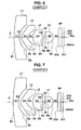
- Figs. 2 to 12 are cross-sectional views illustrating imaging lenses according to Examples 1 to 11.
- Figs. 2 to 12 also show an aperture diaphragm St and an optical member PP.
- the left side is the object side
- the right side is the image side.
- Figs. 2 to 9 do not show the shape or size of the aperture diaphragm St, but show the position thereof on the optical axis Z.
- Table 1 shows lens data and various kinds of data of the imaging lens according to Example 1
- Table 2 shows aspheric data
- Table 3 shows data related to curvature radius.
- Tables 4 to 33 show lens data, various kinds of data, and aspheric data of the imaging lenses according to Examples 2 to 11.
- the surface of a component closest to the object side is given number 1, and the surface number is sequentially increased toward the image side.
- the curvature radius of the i-th surface from the object side is written in the field of a curvature radius Ri, and the surface spacing between the i-th surface and an (i+1)-th surface on the optical axis Z is written in the field of Di.
- the curvature radius of the surface is positive.
- the curvature radius of the surface is negative.
- an optical component arranged closest to the object side is given number 1, and the number is sequentially increased toward the image side.
- the Abbe number of the j-th optical component with respect to the d-line is written in the field of vdj.
- the lens data shown in Table 1 includes the aperture diaphragm St and the optical member PP, and the word (aperture diaphragm) is written in the field of the surface number of a surface corresponding to the aperture diaphragm St.
- Fno. indicates the F number
- 2 ⁇ indicates a total angle of view
- L indicates the distance from the object-side surface of the first lens L1 to the image plane Sim on the optical axis Z (the back focal length, which is an air equivalent length)
- Bf indicates the distance (corresponding to the back focal length, which is an air equivalent length) from the image-side surface of the lens which is arranged closest to the image side to the image plane Sim on the optical axis Z
- f indicates the focal length of the entire system
- f1 indicates the focal length of the first lens L1
- f2 indicates the focal length of the second lens L2
- f3 indicates the focal length of the third lens L
- f4 indicates the focal length of the fourth lens L4
- ED1 indicates the effective diameter of the object-side surface of the first lens L1
- f12 indicates a composite focal length of the first lens L1 and the second lens L2.
- the symbol '*' added to the surface number indicates an aspheric surface.
- the lens data shown in Table 1 includes the curvature radius of the aspheric surface near the optical axis (the curvature radius of the center).
- the aspheric data shown in Table 2 includes the surface number of the aspheric surface and an aspheric coefficient related to each aspheric surface.
- 'En' (n is an integer) means ' ⁇ 10 -n '
- 'E+n' means ' ⁇ 10 n '.
- indicates the absolute value of the curvature radius of the image-side surface of the second lens L2 at the effective diameter edge
- indicates the ratio of the absolute value of the curvature radius of the image-side surface of the second lens L2 at the effective diameter edge and the absolute value of the curvature radius thereof at the center
- indicates the absolute value of the curvature radius of the object-side surface of the third lens L3 at the effective diameter edge
- indicates the ratio of the absolute value of the curvature radius of the object-side surface of the third lens L3 at the effective diameter edge and the absolute value of the curvature radius thereof at the center.
- indicates the absolute value of the curvature radius of the image-side surface of the third lens L3 at the effective diameter edge
- indicates the ratio of the absolute value of the curvature radius of the image-side surface of the third lens L3 at the effective diameter edge and the absolute value of the curvature radius thereof at the center
- indicates the absolute value of the curvature radius of the object-side surface of the fourth lens L4 at the effective diameter edge
- indicates the ratio of the absolute value of the curvature radius of the object-side surface of the fourth lens L4 at the effective diameter edge and the absolute value of the curvature radius thereof at the center.
- indicates the absolute value of the curvature radius of the image-side surface of the fourth lens L4 at the effective diameter edge
- indicates the ratio of the absolute value of the curvature radius of the image-side surface of the fourth lens L4 at the effective diameter edge and the absolute value of the curvature radius thereof at the center.
- Tables 1 to 3 show numerical values with predetermined digits.
- the unit of each numerical value is as follows.
- the unit of 2 ⁇ is 'degree'
- the unit of length is 'mm'.
- these are just illustrative, and other appropriate units may be used since the optical system can be used during proportional enlargement or proportional reduction.
- the first lens L1 is a spherical glass lens.
- One surface or both surfaces of the first lens L1 may be aspheric surfaces.
- the first lens L1 is an aspheric glass lens, it is possible to effectively correct all aberrations.
- the second lens L2, the third lens L3, and the fourth lens L4 are all made of plastic. Therefore, it is possible to manufacture inexpensive lenses with a light weight.
- Table 34 shows values corresponding to Conditional expressions 1 to 15 of the imaging lenses according to Examples 1 to 11.
- the d-line is a reference wavelength
- Table 34 shows each value at the reference wavelength. As can be seen from Table 34, all of Examples 1 to 8 satisfy Conditional expressions 1 to 15.
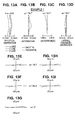
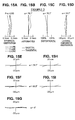
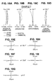
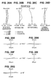
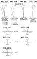
- Figs. 13A to 13I , Figs. 14A to 14I , Figs. 15A to 15I , Figs. 16A to 16I , Figs. 17A to 17I , Figs. 18A to 18I , Figs. 19A to 19I , Figs. 20A to 20I , Figs. 21A to 21I , Figs. 22A to 22I , and Figs. 23A to 23I are aberration diagrams illustrating the spherical aberration, astigmatism, distortion, lateral chromatic aberration, and lateral aberration of the imaging lenses according to Examples 1 to 11.
- Fig. 13A, Fig. 13B, Fig. 13C, and Fig. 13D are aberration diagrams respectively illustrating the spherical aberration, astigmatism, distortion, and lateral chromatic aberration of the imaging lens according to Example 1
- Figs. 13E to 13G are aberration diagrams illustrating lateral aberration in the tangential direction at each angle of view
- Figs. 13H to 13I are aberration diagrams illustrating lateral aberration in the sagittal direction at each angle of view.
- Fno. means the F number.
- ⁇ means a half angle of view.
- the distortion diagram shows the amount of deviation from an ideal image height f ⁇ tan( ⁇ ) (where f indicates the focal length of the entire system and ⁇ indicates an angle of view (which is treated as a variable; 0 ⁇ ⁇ ⁇ ⁇ ).
- Each of the aberration diagrams shows aberration in the tangential direction and the sagittal direction at each half angle of view so as to be aligned with the horizontal direction.
- a diagram illustrating lateral aberration in the sagittal direction on the optical axis is omitted.
- Each aberration diagram shows aberration with respect to the d-line (587.56 nm), which is the reference wavelength.
- the spherical aberration diagram and the lateral chromatic aberration diagram also show aberrations with respect to the F-line (wavelength: 486.13 nm) and the C-line (wavelength: 656.27 nm).
- each of the imaging lenses according to Examples 1 to 11 includes a small number of lenses, for example, four lenses, a small size, a low manufacturing cost, a small F number of 2.0 to 2.8, and a total angle of view of 149° to 184°, which is a wide angle of view.
- the effective diameter of the object-side surface of the first lens L1 is equal to or less than 12 mm and a small portion is exposed to the outside. All aberrations of the imaging lenses are effectively corrected and the imaging lenses have good optical performances.
- the imaging lenses can be appropriately applied to, for example, monitoring cameras or in-vehicle cameras for capturing the images of the front, side and rear of the vehicle.
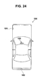
- Fig. 18 shows an example in which an imaging apparatus including the imaging lens according to this embodiment is provided in a vehicle 100.
- the vehicle 100 includes an outside-vehicle camera 101 for capturing the image of a blind spot area of the passenger seat side, an outside-vehicle camera 102 for capturing the image of a blind spot area of the rear side of the vehicle 100, and an in-vehicle camera 103 that is attached to the rear surface of a room mirror and captures the same visual field range as that of a driver.
- the outside-vehicle camera 101, the outside-vehicle camera 102, and the in-vehicle camera 103 are the imaging apparatuses according to the embodiment of the invention, and include the imagine lens according to the embodiment of the invention and an imaging device that converts an optical image formed by the imaging lens into an electric signal.
- the imaging lens according to the embodiment of the invention has the above-mentioned advantages, the outside-vehicle cameras 101 and 102 and the in-vehicle camera 103 do not deteriorate the appearance of the vehicle, have a small size, a low manufacturing cost, a wide angle of view, and can obtain high-quality images.
- the curvature radius, surface spacing, refractive index, Abbe number, and aspheric coefficient of each lens component are not limited to the values described in each numerical example, but may have other values.
- the imaging apparatus is applied to the in-vehicle camera, but the purpose of the invention is not limited thereto.
- the invention can be applied to cameras for portable terminals or monitoring cameras.
Landscapes
- Physics & Mathematics (AREA)
- General Physics & Mathematics (AREA)
- Optics & Photonics (AREA)
- Lenses (AREA)
Abstract
Description
- The present invention relates to an imaging lens and an imaging apparatus, and more particularly, to an imaging lens suitable for, for example, an in-vehicle camera, a camera for a portable terminal, and a monitoring camera using an imaging device, such as a CCD (Charge Coupled Device) or a CMOS (Complementary Metal Oxide Semiconductor), and an imaging apparatus including the imaging lens.
- In recent years, the size of an imaging device, such as a CCD or a CMOS has been significantly reduced and the number of pixels thereof has significantly increased. In addition, the size of an imaging apparatus body including the imaging device has been reduced, and there is an increasing demand for an imaging lens with a good optical performance and a small size. For example, there is a demand for a lens that is provided in, for example, the in-vehicle camera or the monitoring camera and has a small size, high weather resistance, a light weight, and a low manufacturing cost.
- For example,
JP-A-2002-244031 JP-A-2005-227426 JP-A-2006-259704 JP-A-2007-206516 JP-A-2002-244031 JP-A-2005-227426 JP-A-2006-259704 JP-A-2007-206516 - However, in recent years, there is an increasing demand for a wide-angle lens provided in, for example, the in-vehicle camera or the monitoring camera, in addition to the above-mentioned structure demands. However, as in the related art, when only the angle of view of the lens is increased, the effective diameter of a lens that is arranged closest to the object side increases with the increase in the angle of view and the diameter of the lens increases, which makes it difficult to reduce the size of the lens. In particular, in the in-vehicle camera or the camera for a portable terminal, there is a demand for a lens in which a small portion is exposed to the outside such that the outward appearance does not deteriorate. Therefore, there is a strong desire to reduce the size of the lens system in the diametric direction. For example, in the monitoring camera, it is necessary to reduce the size of the lens system in the diametric direction in order to make the camera as invisible as possible. That is, there is a demand for a lens system capable of meeting two opposite requirements, that is, an increase in the angle of view and a reduction in the size of the lens system in the diametric direction.
- The invention has been made in order to solve the above-mentioned problems, and an object of the invention is to provide an imaging lens that is capable of reducing the size of a lens system in the diametric direction, which results in a small size, while obtaining a wide angle of view and has a good optical performance, and an imaging apparatus including the imaging lens.
- A first imaging lens according to the invention includes a first negative lens having a meniscus shape in which a concave surface faces an image side, a second negative lens having a meniscus shape in which a concave surface faces the image side and including at least one aspheric surface, a third positive lens including at least one aspheric surface, an aperture diaphragm, and a fourth positive lens including at least one aspheric surface, which are arranged in this order from an object side. The imaging lens satisfies the following Conditional expression 1:

(where f indicates the focal length of the entire system and f2 indicates the focal length of the second lens). - A second imaging lens according to the invention includes a first negative lens having a meniscus shape in which a concave surface faces an image side, a second negative lens having a meniscus shape in which a concave surface faces the image side and including at least one aspheric surface, a third positive lens including at least one aspheric surface, an aperture diaphragm, and a fourth positive lens including at least one aspheric surface, which are arranged in this order from an object side. The imaging lens satisfies the following Conditional expression 2:

(where ED1 indicates the effective diameter of an object-side surface of the first lens and D1 indicates the thickness of the center of the first lens). - The first and second imaging lenses according to the invention may satisfy the following
Conditional expressions 3 to 10:


(where DX3 indicates the distance between an intersection point between the optical axis and a perpendicular line that drops from the effective diameter edge to the optical axis and the center of the object-side surface of the second lens in an optical axis direction when the effective diameter edge is arranged closer to the image side than to an intersection point between the object-side surface and the optical axis, f indicates the focal length of the entire system, RX3 indicates the curvature radius of the object-side surface of the second lens at the effective diameter edge, R3 indicates the curvature radius of the object-side surface of the second lens at the center, L indicates the distance from an object-side surface of the first lens to an image plane in the optical axis direction (a back focal length is an air-equivalent length), f1 indicates the focal length of the first lens, D2 indicates an air space between the first lens and the second lens on the optical axis, f12 indicates a composite focal length of the first lens and the second lens, and R1 indicates the curvature radius of the object-side surface of the first lens). - As a preferred aspect, the first and second imaging lenses may satisfy any one of the following
Conditional expressions 3 to 10 or a combination of two or more Conditional expressions. - In the first and second imaging lenses according to the invention, the 'meniscus shape in which a concave surface faces the image side' is considered in a paraxial region of the aspheric lens. In the first and second imaging lenses according to the invention, the 'negative' or 'positive' power (refractive power) is considered in the paraxial region. In the imaging lenses according to the invention, when a surface is convex to the object side, the curvature radius of the surface is positive, and when a surface is convex to the image side, the curvature radius of the surface is negative.
- When intersections points between all light beams contributing to forming an image and the lens surface are considered, the 'effective diameter of the surface' means the diameter of a circle formed by the outermost points (points furthest away from the optical axis) in the diametric direction, and the 'effective diameter edge' means the outermost point. In the system that is rotationally symmetric with respect to the optical axis, the outermost points form a circle. However, in the system that is not rotationally symmetric, the outermost points may not form a circle. In this case, the diameter of an equivalent circle may be used as the effective diameter.
- An imaging apparatus according to the invention includes the imaging lens according to the invention.
- According to the first imaging lens of the invention, in the lens system including at least four lenses, the shapes of the first lens and the second lens are appropriately set, an aspheric surface is provided in each of the second to fourth lenses, and the arrangement of the power of the entire system and the position of the aperture diaphragm are appropriately set, such that the imaging lens satisfies
Conditional expression 1. Therefore, it is possible to achieve an imaging lens that has a wide angle of view, a small lens system in the diametric direction, a small size, and a good optical performance. - According to the second imaging lens of the invention, in the lens system including at least four lenses, the shapes of the first lens and the second lens are appropriately set, an aspheric surface is provided in each of the second to fourth lenses, and the arrangement of the power of the entire system and the position of the aperture diaphragm are appropriately set, such that the imaging lens satisfies
Conditional expression 2. Therefore, it is possible to achieve an imaging lens that has a wide angle of view, a small lens system in the diametric direction, a small size, and a good optical performance. - The imaging apparatus according to the invention includes the first imaging lens or the second imaging lens according to the invention. Therefore, it is possible to reduce the area of the lens exposed to the outside and the size of the imaging apparatus, and obtain a high-quality image at a wide angle of view.
-
-
Fig. 1 is a diagram illustrating the structure of an imaging lens according to an embodiment of the invention; -
Fig. 2 is a cross-sectional view illustrating the structure of an imaging lens according to Example 1 of the invention; -
Fig. 3 is a cross-sectional view illustrating the structure of an imaging lens according to Example 2 of the invention; -
Fig. 4 is a cross-sectional view illustrating the structure of an imaging lens according to Example 3 of the invention; -
Fig. 5 is a cross-sectional view illustrating the structure of an imaging lens according to Example 4 of the invention; -
Fig. 6 is a cross-sectional view illustrating the structure of an imaging lens according to Example 5 of the invention; -
Fig. 7 is a cross-sectional view illustrating the structure of an imaging lens according to Example 6 of the invention; -
Fig. 8 is a cross-sectional view illustrating the structure of an imaging lens according to Example 7 of the invention; -
Fig. 9 is a cross-sectional view illustrating the structure of an imaging lens according to Example 8 of the invention; -
Fig. 10 is a cross-sectional view illustrating the structure of an imaging lens according to Example 9 of the invention; -
Fig. 11 is a cross-sectional view illustrating the structure of an imaging lens according to Example 10 of the invention; -
Fig. 12 is a cross-sectional view illustrating the structure of an imaging lens according to Example 11 of the invention; -
Figs. 13A to 13I are diagrams illustrating aberrations of the imaging lens according to Example 1 of the invention; -
Figs. 14A to 14I are diagrams illustrating aberrations of the imaging lens according to Example 2 of the invention; -
Figs. 15A to 15I are diagrams illustrating aberrations of the imaging lens according to Example 3 of the invention; -
Figs. 16A to 16I are diagrams illustrating aberrations of the imaging lens according to Example 4 of the invention; -
Figs. 17A to 17I are diagrams illustrating aberrations of the imaging lens according to Example 5 of the invention; -
Figs. 18A to 18I are diagrams illustrating aberrations of the imaging lens according to Example 6 of the invention; -
Figs. 19A to 19I are diagrams illustrating aberrations of the imaging lens according to Example 7 of the invention; -
Figs. 20A to 20I are diagrams illustrating aberrations of the imaging lens according to Example 8 of the invention; -
Figs. 21A to 21I are diagrams illustrating aberrations of the imaging lens according to Example 9 of the invention; -
Figs. 22A to 22I are diagrams illustrating aberrations of the imaging lens according to Example 10 of the invention; -
Figs. 23A to 23I are diagrams illustrating aberrations of the imaging lens according to Example 11 of the invention; and -
Fig. 24 is a diagram illustrating the arrangement of in-vehicle imaging apparatuses according to an embodiment of the invention. - Hereinafter, exemplary embodiments of the invention will be described in detail with reference to the accompanying drawings. First, an imaging lens according to an embodiment of the invention will be described with reference to
Fig. 1. Fig. 1 is a cross-sectional view illustrating animaging lens 1 according to an embodiment of the invention and shows on-axis light beams 2 from an object point that is disposed at an infinite distance and off-axis light beams 3 and 4 at a total angle of view 2ω. InFig. 1 , the left side is an object side and the right side is an image side. -
Fig. 1 also shows animaging device 5 that is provided on an image plane Sim including an image point Pim of theimaging lens 1, considering the case in which theimaging lens 1 is applied to an imaging apparatus. Theimaging device 5 converts an optical image formed by theimaging lens 1 into electric signals, and may be, for example, a CCD image sensor or a CMOS image sensor. - When the
imaging lens 1 is applied to an imaging apparatus, it is preferable to provide a cover glass, a low pass filter, or an infrared cut filter according to the structure of a camera provided with the lens.Fig. 1 shows an example in which a parallel-plate-shaped optical member PP is arranged between a lens that is arranged closest to the image side and the imaging device 5 (image surface Sim), considering the above-mentioned case. - The
imaging lens 1 includes as basic components a first negative lens L1, which is a meniscus lens having a concave surface facing the image side, a second negative lens L2, which is a meniscus lens having a concave surface facing the image side and including at least one aspheric surface, a third positive lens L3 including at least one aspheric surface, an aperture diaphragm St, and a fourth positive lens L4 including at least one aspheric surface, which are arranged in this order from the object side.Fig. 1 does not show the shape or size of the aperture diaphragm St, but shows the position of the aperture diaphragm St on the optical axis Z. - The imaging lens includes a small number of lenses, for example, four lenses. Therefore, it is possible to reduce manufacturing costs and reduce the total length of the lens in the optical axis direction. Since three lenses, that is, the second lens L2, the third lens L3, and the fourth lens L4 are aspheric lenses, it is possible to effectively correct all aberrations with a small number of lenses. Therefore, it is possible to reduce the size of the lens and improve the optical performance.
- Since two lenses arranged on the object side, that is the first lens L1 and the second lens L2 are both negative meniscus lenses having a concave surface facing the image side, it is possible to capture light beams at a wide angle of view and achieve a wide-angle lens system. In addition, since two negative lenses are provided, the function of correcting each aberration required for the negative lenses can be shared by the two lenses, and it is possible to effectively correct aberration.
- Since each of the third lens L3 and the fourth lens L4 has a positive power and includes at least one aspheric surface, it is possible to effectively correct field curvature. Since two positive lenses, that is, the third lens L3 and the fourth lens L4 are arranged on the image side, the function of focusing an image on the image surface and the function of correcting each aberration required for the positive lens can be shared by the two lenses, and it is possible to effectively correct aberration.
- Since the aperture diaphragm St is arranged between the third lens L3 and the fourth lens L4, it is possible to reduce the light beam height of the first lens L1, as compared to the structure in which the aperture diaphragm St is arranged on the image side of the fourth lens L4. Therefore, it is possible to reduce the size of the lens system in the diametric direction. In addition, it is easy to correct field curvature and lateral chromatic aberration.
- The
imaging lens 1 shown inFig. 1 includes the following first and second aspects, in addition to the above-mentioned basic structure. In the first aspect, when the focal length of the entire system is f and the focal length of the second lens L2 is f2, theimaging lens 1 satisfies the following Conditional expression 1:
- If the upper limit of
Conditional expression 1 is satisfied, it is possible to prevent the power of the second lens L2 from being too strong and thus prevent a light beam from being refracted at a large angle by the second lens L2. Therefore, it is possible to reduce the light beam height of the first lens L1. As a result, it is possible to reduce the size of the lens system in the diametric direction. - In addition, it is preferable that the imaging lens satisfy the following Conditional expression 1-2:

- If the upper limit of Conditional expression 1-2 is satisfied, it is easy to reduce the size of the lens system in the diametric direction. If the lower limit of Conditional expression 1-2 is satisfied, it is possible to prevent the power of the second lens L2 from being too weak and set the power of the second lens L2 to an appropriate value. Therefore, it is possible to increase the angle of view and a back focal length. When the power of the second lens L2 is too weak, the light beam needs to be refracted at a large angle by the first lens L1 in order to increase the angle of view. Therefore, it is difficult to correct distortion.
- In order to easily reduce the size of the lens system in the diametric direction, increase the angle of view, ensure a back focal length, and correct distortion, it is preferable that the imaging lens satisfy the following Conditional expression 1-3:

- In the second aspect, when the effective diameter of an object-side surface of the first lens L1 is ED1 and the thickness of the center of the first lens L1 is D1, the imaging lens satisfies the following Conditional expression 2:

- If the ratio is more than the upper limit of
Conditional expression 2, the effective diameter of the object-side surface of the first lens L1 increases, which results in an increase in the size of the lens system in the diametric direction, or the thickness of the center of the first lens L1 is too small, which may cause the first lens L1 to be broken easily. When the imaging lens is used as, for example, an in-vehicle camera, it is preferable that the first lens L1 be thick and be less likely to be broken since the first lens needs to be resistant to various kinds of impact. If the ratio is less than the lower limit ofConditional expression 2, it is easy to reduce the size of the lens system in the diametric direction, but the effective diameter of the object-side surface of the first lens L1 is too small. Therefore, it is difficult to separate the on-axis light beam from the off-axis light beam and thus effectively correct field curvature and distortion, or the thickness of the first lens L1 is too large, which results in an increase in the size of the lens system in the optical axis direction. - In order to more easily obtain the effects when
Conditional expression 2 is satisfied, that is, in order to more easily reduce the size of the lens system in the diametric direction and the optical axis direction and correct field curvature and distortion, it is preferable that the imaging lens satisfy the following Conditional expression 2-2:
- In order to more easily obtain the effects when Conditional expression 2-2 is satisfied, that is, in order to more easily reduce the size of the lens system in the diametric direction and the optical axis direction and correct field curvature and distortion, it is preferable that the imaging lens satisfy the following Conditional expression 2-3:
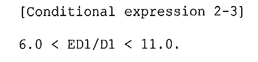
- In order to more easily obtain the effects when Conditional expression 2-3 is satisfied, that is, in order to more easily reduce the size of the lens system in the diametric direction and the optical axis direction and correct field curvature and distortion, it is preferable that the imaging lens satisfy the following Conditional expression 2-4:

- In order to more easily obtain the effects when Conditional expression 2-4 is satisfied, that is, in order to more easily reduce the size of the lens system in the diametric direction and the optical axis direction and correct field curvature and distortion, it is preferable that the imaging lens satisfy the following Conditional expression 2-5:

- The imaging lens including the first aspect may include the structure of the second aspect or a preferred structure according to the second aspect. Similarly, the imaging lens including the second aspect may include the structure according to the first aspect.
- It is preferable that the imaging lens including the first or second aspect have the following structures. As a preferred aspect, the imaging lens may have any one of the following structures or a combination of two or more structures.
- The object-side surface of the second lens L2 is configured such that an effective diameter edge is disposed at a position closer to the image side than an intersection point between the object-side surface and the optical axis. When the distance between an intersection point between the optical axis Z and a perpendicular line that drops from the effective diameter edge to the optical axis Z and the center of the object-side surface in the optical axis direction is DX3, it is preferable that the imaging lens satisfy the following Conditional expression 3:

- In the example shown in
Fig. 1 , a point X3 is a point at the effective diameter edge of the object-side surface of the second lens L2, a point XH3 indicates an intersection point between the optical axis Z and the perpendicular line that drops from the point X3 to the optical axis Z, and a point C3 is a central point. - When the object-side surface of the second lens L2 is formed in a shape satisfying
Conditional expression 3, it is possible to reduce the angle formed between the light beam incident on the object-side surface and a normal line of the object-side surface and thus prevent the light beam from being refracted at a large angle. Therefore, it is easy to reduce the size of the lens system in the diametric direction. - In order to reduce the size of the lens system in the diametric direction, it is more preferable that the second lens L2 satisfy the following Conditional expression 3-2:

- In order to further reduce the size of the lens system in the diametric direction, it is more preferable that the second lens L2 satisfy the following Conditional expression 3-3:

- In order to further reduce the size of the lens system in the diametric direction, it is most preferable that the second lens L2 satisfy the following Conditional expression 3-4:

- When the focal length of the entire system is f and the curvature radius of the object-side surface of the second lens L2 at the effective diameter edge is RX3, it is preferable that the imaging lens satisfy the following Conditional expression 4:

- The curvature radius RX3 will be described below.
- If the ratio is less than the lower limit of
Conditional expression 4, the curvature radius RX3 of the object-side surface of the second lens L2 at the effective diameter edge is too small, and the angle formed between the light beam and the normal line of the object-side surface at the effective diameter edge increases. Therefore, the light beam is refracted at a large angle by the object-side surface, and it is difficult to reduce the size of the lens system in the diametric direction and effectively correct field curvature. - It is preferable that the imaging lens satisfy the following Conditional expression 4-2:

- When the lower limit of Conditional expression 4-2 is satisfied, it is possible to further improve the effects obtained when the upper limit of
Conditional expression 4 is satisfied. - In addition, it is preferable that the imaging lens satisfy the following Conditional expression 4-3:

- If the ratio is more than the upper limit Conditional expression 4-3, it is difficult to obtain a wide angle of view. In order to obtain a wide angle of view, the first lens L1 needs to refract the light beam at a large angle. Therefore, it is difficult to correct distortion and a peripheral image is reduced and formed. As a result, even though an image captured by the imaging device is enlarged by image processing, the resolution of the image is reduced, and it is difficult to prevent the deterioration of image quality. When the lower limit of Conditional expression 4-3 is satisfied, it is possible to further improve the effects obtained when Conditional expression 4-2 is satisfied.
- It is more preferable that the imaging lens satisfy the following Conditional expression 4-4:

- When the upper limit of Conditional expression 4-4 is satisfied, it is possible to further improve the effects obtained when the upper limit of Conditional expression 4-3 is satisfied.
- When the focal length of the entire system is f and the curvature radius of the object-side surface of the second lens L2 at the center is R3, it is preferable that the imaging lens satisfy the following Conditional expression 5:

- If the ratio is more than the upper limit of
Conditional expression 5, the curvature radius of the object-side surface of the second lens L2 at the center is too large. It is preferable that the power of the object-side surface of the second lens L2 be reduced toward the periphery thereof, which will be described below. Therefore, when the curvature radius of the second lens L2 at the center is too large, the curvature radius of a peripheral portion of the second lens is also too large. Therefore, in particular, the incident angle of the light beam on the surface in the periphery of the second lens is too large, and the light beam is refracted at a large angle by the object-side surface of the second lens L2. As a result, the height of the light beam passing through the first lens L1 increases, and it is difficult to reduce the size of the lens system in the diametric direction. If the ratio is less than the lower limit ofConditional expression 5, the curvature radius of the object-side surface of the second lens L2 at the center is too small, and it is difficult to process the second lens L2. - It is more preferable that the imaging lens satisfy the following Conditional expression 5-2:

- When the upper limit of Conditional expression 5-2 is satisfied, it is possible to further improve the effects obtained when the upper limit of
Conditional expression 5 is satisfied. - It is most preferable that the imaging lens satisfy the following Conditional expression 5-3:

- When Conditional expression 5-3 is satisfied, it is possible to further improve the effects obtained when Conditional expression 5-2 is satisfied.
- When the focal length of the entire system is f and the distance from the object-side surface of the first lens L1 to the image plane Sim in the optical axis direction is L, it is preferable that the imaging lens satisfy the following Conditional expression 6:

- When the distance L is calculated, the back focal length is an air-equivalent length. That is, for example, when a cover glass or a filter is provided between a lens that is arranged closest to the image side and the image surface Sim, the thickness of the cover glass or the filter is an air-equivalent value.
- If the ratio is more than the upper limit of
Conditional expression 6, the size of the system increases. If the ratio is less than the lower limit ofConditional expression 6, it is difficult to obtain a sufficiently wide angle of view. When a wide angle of view is obtained, the angle of view is increased by distortion, which results in an increase in the distortion of an image in the periphery of an imaging area, or the total length of the lens system is reduced, which results in a reduction in the size of each lens. As a result, it is difficult to manufacture the imaging lens, or the manufacturing costs of the imaging lens increase. - It is more preferable that the imaging lens satisfy the following Conditional expression 6-2:

- When the upper limit of Conditional expression 6-2 is satisfied, it is possible to further improve the effects obtained when the upper limit of
Conditional expression 6 is satisfied. - It is most preferable that the imaging lens satisfy the following Conditional expression 6-3:

- When Conditional expression 6-3 is satisfied, it is possible to further improve the effects obtained when Conditional expression 6-2 is satisfied.
- When the focal length of the entire system is f and the focal length of the first lens L1 is f1, it is preferable that the imaging lens satisfy the following Conditional expression 7:

- If the ratio is more than the upper limit of
Conditional expression 7, the power of the first lens L1 becomes strong and it is easy to obtain a wide angle of view. However, it is difficult to correct distortion since marginal rays are refracted at a large angle by the object-side surface, or the light beam height of the object-side surface increases since the light beam is refracted at a large angle by the image-side surface, which results in an increase in the size of the lens system in the diametric direction. If the ratio is less thanConditional expression 7, the power of the first lens L1 is too weak and it is difficult to obtain a wide angle of view. Therefore, a sufficient angle of view is not obtained. - It is more preferable that the imaging lens satisfy the following Conditional expression 7-2:

- When Conditional expression 7-2 is satisfied, it is possible to further improve the effects obtained when
Conditional expression 7 is satisfied. - It is more preferable that the imaging lens satisfy the following Conditional expression 7-3:

- When Conditional expression 7-3 is satisfied, it is possible to further improve the effects obtained when Conditional expression 7-2 is satisfied.
- When the focal length of the entire system is f and an air space between the first lens L1 and the second lens L2 on the optical axis is D2, it is more preferable that the imaging lens satisfy the following Conditional expression 8:

- If the ratio is more than the upper limit of
Conditional expression 8, the gap between the first lens L1 and the second lens L2 increases, which results in an increase in the diameter of the first lens L1, or the power of the first lens is too strong in order to reduce the size in the diametric direction, which makes it difficult to correct distortion. If the ratio is less than the lower limit ofConditional expression 8, the distance between the first lens L1 and the second lens L2 is too small, and the on-axis light beams and the marginal rays are insufficiently separated from each other. As a result, it is difficult to correct field curvature. - It is more preferable that the imaging lens satisfy the following Conditional expression 8-2:

- When the upper limit of Conditional expression 8-2 is satisfied, it is possible to further improve the effects obtained when the upper limit of
Conditional expression 8 is satisfied. - It is most preferable that the imaging lens satisfy the following Conditional expression 8-3:

- When Conditional expression 8-3 is satisfied, it is possible to further improve the effects obtained when Conditional expression 8-2 is satisfied.
- When the focal length of the entire system is f and a composite focal length of the first lens L1 and the second lens L2 is f12, it is preferable that the imaging lens satisfy the following Conditional expression 9:

- If the ratio is more than the upper limit of
Conditional expression 9, it is possible to easily obtain a wide angle of view, but field curvature increases. Therefore, it is difficult to obtain a high-quality image. If the ratio is less than the lower limit ofConditional expression 9, the power of two negative lenses that are arranged closest to the object side becomes weak. Therefore, it is difficult to refract the light beams at a large angle and thus obtain a wide angle of view, or the size of the lens system increases in order to obtain a wide angle of view. - It is more preferable that the imaging lens satisfy the following Conditional expression 9-2:

- When the lower limit of Conditional expression 9-2 is satisfied, it is easy to reduce the size of the lens system while obtaining a wide angle of view.
- It is more preferable that the imaging lens satisfy the following Conditional expression 9-3:

- When the lower limit of Conditional expression 9-3 is satisfied, it is easy to reduce the size of the lens system while obtaining a wide angle of view.
- When the focal length of the entire system is f and the curvature radius of the object-side surface of the first lens L1 is R1, it is preferable that the imaging lens satisfy the following Conditional expression 10:

- If the ratio is more than the upper limit of
Conditional expression 10, the curvature radius of the object-side surface of the first lens L1 is too large, and it is possible to easily reduce the size of the lens in the diametric direction. However, the light beam is refracted at a wide angle and distortion increases. In addition, the image in the periphery of the imaging area is reduced and formed. Therefore, even though the image captured by the imaging device is enlarged by image processing, the resolution of the image is reduced, and it is difficult to prevent the deterioration of image quality. If the ratio is less than the lower limit ofConditional expression 10, the curvature radius of the object-side surface of the first lens L1 is too small and the image-side surface of the first lens L1 or the second lens L2 needs to refract the light beam at a large angle in order to obtain a wide angle of view. As a result, the light beam height of the object-side surface of the first lens L1 increases, which makes it difficult to reduce the size of the lens. In addition, the curvature radius of the image-side surface of the first lens L1 needs to be reduced in order to refract the light beam at a large angle with the image-side surface of the first lens L1. In this case, it is difficult to process the first lens or the manufacturing costs of the lens increase. - It is preferable that the imaging lens satisfy the following Conditional expression 10-2:

- When Conditional expression 10-2 is satisfied, it is possible to further improve the effects obtained when
Conditional expression 10 is satisfied. - It is preferable that the imaging lens satisfy the following Conditional expression 10-3:

- When Conditional expression 10-3 is satisfied, it is possible to further improve the effects obtained when Conditional expression 10-2 is satisfied.
- When the focal length of the entire system is f and the air space between the second lens L2 and the third lens L3 on the optical axis is D4, it is preferable that the imaging lens satisfy the following Conditional expression 11:
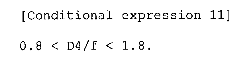
- If the ratio is more than the upper limit of
Conditional expression 11, the length of the lens system in the optical axis direction increases, and the outside diameter of the first lens L1 also increases, which results in an increase in the size of the entire system. If the ratio is less than the lower limit ofConditional expression 11, the gap between the second lens L2 and the third lens L3 is reduced. When the gap between the second lens L2 and the third lens L3 is reduced, the aspheric shape of the image-side surface of the second lens L2 is restricted, and it is difficult to correct field curvature and distortion. - It is preferable that the imaging lens satisfy the following Conditional expression 11-2:

- When Conditional expression 11-2 is satisfied, it is possible to further improve the effects obtained when
Conditional expression 11 is satisfied. - When the focal length of the entire system is f and the thickness of the center of the second lens L2 is D3, it is preferable that the imaging lens satisfy the following Conditional expression 12:

- If the ratio is more than the upper limit of
Conditional expression 12, the thickness of the second lens L2 is too large and the size of the lens system increases. If the ratio is less than the lower limit ofConditional expression 12, the thickness of the center of the second lens L2 is too small, and it is easy to reduce the size of the lens. However, in this case, since the thickness ratio of a peripheral portion (the ratio of the thickness of the peripheral portion of the lens to the thickness of the center of the lens in the optical axis direction) increases, it is difficult to mold the lens. - It is preferable that the imaging lens satisfy the following Conditional expression 12-2:

- When Conditional expression 12-2 is satisfied, it is possible to further improve the effects obtained when
Conditional expression 12 is satisfied. - When the curvature radius of the object-side surface of the second lens L2 at the center is R3 and the curvature radius of the image-side surface of the second lens L2 at the center R4, it is preferable that the imaging lens satisfy the following Conditional expression 13:

- If the ratio is more than the upper limit of Conditional expression 13, the difference between the curvature radii of the object-side surface and the image-side surface of the second lens L2 increases, and the light beam is refracted at a large angle by the second lens L2. Therefore, it is difficult to reduce the size of the lens in the diametric direction. If the ratio is less than the lower limit of Conditional expression 13, the difference between the curvature radii of the object-side surface and the image-side surface of the second lens L2 is too small, and the power of the second lens L2 is too weak. Therefore, it is difficult to obtain a wide angle of view.
- It is preferable that the imaging lens satisfy the following Conditional expression 13-2:

- When the upper limit of Conditional expression 13-2 is satisfied, it is possible to further improve the effects obtained when the upper limit of Conditional expression 13 is satisfied.
- It is more preferable that the imaging lens satisfy the following Conditional expression 13-3:
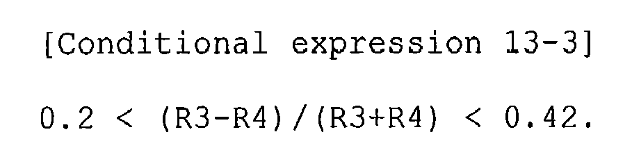
- When Conditional expression 13-3 is satisfied, it is possible to further improve the effects obtained when Conditional expression 13-2 is satisfied.
- When the focal length of the entire system is f and the thickness of the center of the first lens L1 is D1, it is preferable that the imaging lens satisfy the following Conditional expression 14:

- If the ratio is more than the upper limit of Conditional expression 14, the thickness of the first lens L1 is too large, and it is difficult to reduce the size of the lens system in the optical axis direction and the diametric direction. If the ratio is less than the lower limit of Conditional expression 14, the thickness of the first lens L1 is too small, and it is easy to reduce the size of the lens. However, the resistance of the lens to various kinds of impact is reduced. For example, when the imaging lens is used for an in-vehicle camera or a monitoring camera, the imaging lens needs to be resistant to various kinds of impact since the first lens L1 is exposed to the outside. Therefore, it is not preferable the thickness of the first lens L1 be too small.
- It is preferable that the imaging lens satisfy the following Conditional expression 14-2:

- When Conditional expression 14-2 is satisfied, it is possible to further improve the effects obtained when Conditional expression 14 is satisfied.
- When the focal length of the entire system is f and the distance from the image-side surface of the lens closest to the image side (the fourth lens L4 in the example shown in
Fig. 1 ) to the image plane Sim on the optical axis is Bf, it is preferable that Bf/f be in the range of 1.0 to 2.4. When 1.0 < Bf/f < 2.4 is satisfied, it is easy to ensure a sufficient back focal length while preventing an increase in the size of the lens system. It is more preferable that 2 < Bf/f < 2.4 be satisfied. Bf is an air-equivalent length. That is, when a cover glass or a filter is provided between a lens that is arranged closest to the image side and the image plane Sim, the thickness of the cover glass or the filter is an air-equivalent value. - It is preferable that the object-side surface of the second lens L2 be an aspheric surface. It is preferable that the object-side surface of the second lens L2 have a shape in which the object-side surface has a positive power at the center and the positive power at the effective diameter edge is lower than that at the center. When the object-side surface of the second lens L2 has the above-mentioned shape, it is possible to reduce the angle formed between the light beam and the normal line of the object-side surface at the effective diameter edge, and the object-side surface can focus the light beam without refracting the light beam at a large angle. In addition, it is easy to reduce the size of the lens system in the diametric direction, and it is possible to effectively correct field curvature and distortion.
- Next, the shape of the object-side surface of the second lens L2 will be described with reference to
Fig. 1 . InFig. 1 , the point C3 is the center of the object-side surface of the second lens L2 and is also an intersection point between the optical axis Z and the object-side surface of the second lens L2. InFig. 2 , the point X3 is at the effective diameter edge of the object-side surface of the second lens L2 and is an intersection point between the outermostlight beam 6 included in the off-axis light beams 4 and the object-side surface of the second lens L2. - In this case, as shown in
Fig. 1 , an intersection point between the optical axis Z and the normal line of the lens surface at the point X3 is defined as a point P3, a segment X3-P3 linking the point X3 and the point P3 is defined as a curvature radius RX3 at the point X3, and the length |X3-P3| of the segment X3-P3 is defined as the absolute value |RX3| of the curvature radius RX3. That is, |X3-P3| is equal to |RX3|. In addition, the curvature radius at the point C3, that is, the curvature radius of the object-side surface of the second lens L2 at the center is defined as R3 and the absolute value of the curvature radius is defined as |R3| (not shown inFig. 1 ). - The object-side surface of the second lens L2 'having a positive power at the center' means that a paraxial region including the point C3 in the object-side surface has a convex shape. The shape of the object-side surface of the second lens L2 in which 'the positive power at the effective diameter edge is lower than that at the center' means a shape in which the point P3 is closer to the image side than the point C3 and the absolute value |RX3| of the curvature radius at the point X3 is more than the absolute value |R3| of the curvature radius at the point C3.
- In
Fig. 1 , for ease of understanding, a circle CC3 that passes through the point C3 in the radius |R3| and has its center on the optical axis is represented by a dotted line, and a circle CX3 that passes through the point X3 in the radius |RX3| and has its center on the optical axis is represented by a two-dot chain line. The circle CX3 is larger than the circle CC3 and |R3| < |RX3| is established. - It is preferable that the absolute value |RX3| of the curvature radius at the point X3 be three times or more than the absolute value |R3| of the curvature radius at the point C3. In this case, it is easy to reduce the size of the lens system in the diametric direction. It is more preferable that the absolute value |RX3| be four times or more than the absolute value |R3|. In this case, it is easier to reduce the size of the lens system in the diametric direction.
- It is preferable that the image-side surface of the second lens L2 be an aspheric surface. It is preferable that the image-side surface of the second lens L2 have a shape in which the image-side surface has a negative power at the center and the negative power at the effective diameter edge is lower than that at the center. When the image-side surface of the second lens L2 has the above-mentioned shape, it is possible to transmit light to the third lens L3, without refracting marginal rays at a large angle, and focus the light with the subsequent lens. Therefore, it is easy to effectively correct distortion. In addition, since the image-side surface of the second lens L2 does not refract the marginal rays at a large angle, it is possible to reduce the size of the lens system in the diametric direction.
- The shape of the image-side surface of the second lens L2 is the same as that of the object-side surface of the second lens L2 which has been described with reference to
Fig. 1 , and can be considered as follows. In a cross-sectional view of the lens, when the effective diameter edge of the image-side surface of the second lens L2 is a point X4 and an intersection point between the optical axis Z and a normal line at the point X4 is a point P4, a segment X4-P4 linking the point X4 and the point P4 is defined as a curvature radius at the point X4, and the length |X4-P4| of the segment linking the point X4 and the point P4 is defined as the absolute value |RX4| of the curvature radius at the point X4. That is, |X4-P4| is equal to |RX4|. In addition, an intersection point between the optical axis Z and the image-side surface of the second lens L2, that is, the center of the image-side surface of the second lens L2 is defined as a point C4. The absolute value of the curvature radius at the point C4 is defined as |R4|. - The shape of the image-side surface of the second lens L2 in which 'the image-side surface has a negative power at the center and the negative power at the effective diameter edge is lower than that at the center' means a shape in which a paraxial region including the point C4 has a concave shape, the point P4 is closer to the image side than the point C4, and the absolute value |RX4| of the curvature radius at the point X4 is more than the absolute value |R4| of the curvature radius at the point C4.
- It is preferable that the absolute value |RX4| of the curvature radius at the point X4 and the absolute value |R4| of the curvature radius at the point C4 satisfy the following Conditional expression 15:

- If the ratio is less than the lower limit of Conditional expression 15, it is difficult to effectively correct distortion and reduce the size of the lens system in the diametric direction.
- It is more preferable that the absolute values satisfy the following Conditional expression 15-2:

- When Conditional expression 15-2 is satisfied, it is possible to further improve the effects obtained when Conditional expression 15 is satisfied.
- It is most preferable that the absolute values satisfy the following Conditional expression 15-3:

- When the upper limit of Conditional expression 15-3 is satisfied, it is possible to prevent the curvature radius from being too large at the effective diameter edge. In addition, it is easy to obtain a wide angle of view and correct field curvature. If the lower limit of Conditional expression 15-3 is satisfied, it is possible to further improve the effects obtained when Conditional expression 15-2 is satisfied.
- It is preferable that the absolute value |RX4| of the curvature radius at the point X4 be 1.5 times or more than the focal length f of the entire system. When the absolute value |RX4| is 1.5 times or more than the focal length f, it is easy to correct distortion and field curvature. It is more preferable that the absolute value |RX4| be 1.8 times or more than the focal length f. In this case, it is easier to correct distortion and field curvature.
- It is preferable that the object-side surface of the third lens L3 be an aspheric surface. It is preferable that the object-side surface of the third lens L3 have a shape in which the object-side surface has a positive power at the center and the positive power at the effective diameter edge is higher than that at the center. When the object-side surface of the third lens L3 has the above-mentioned shape, it is possible to effectively correct field curvature and lateral chromatic aberration.
- The shape of the object-side surface of the third lens L3 is the same as that of the object-side surface of the second lens L2 which has been described with reference to
Fig. 1 , and can be considered as follows. In a cross-sectional view of the lens, when the effective diameter edge of the object-side surface of the third lens L3 is a point X5 and an intersection point between the optical axis Z and a normal line at the point X5 is a point P5, a segment X5-P5 linking the point X5 and the point P5 is defined as a curvature radius at the point X5, and the length |X5-P5| of the segment linking the point X5 and the point P5 is defined as the absolute value |RX5| of the curvature radius at the point X5. That is, |X5-P5| is equal to |RX5|. In addition, an intersection point between the optical axis Z and the object-side surface of the third lens L3, that is, the center of the object-side surface of the third lens L3 is defined as a point C5. The absolute value of the curvature radius at the point C5 is defined as |R5|. - The shape of the object-side surface of the third lens L3 in which 'the object-side surface has a positive power at the center and the positive power at the effective diameter edge is higher than that at the center' means a shape in which a paraxial region including the point C5 has a convex shape, the point P5 is closer to the image side than the point C5, and the absolute value |RX5| of the curvature radius at the point X5 is less than the absolute value |R5| of the curvature radius at the point C5.
- It is preferable that the absolute value |RX5| of the curvature radius at the point X5 be equal to or less than nine-tenths (0.9) of the absolute value |R5| of the curvature radius at the point C5. In this case, it is possible to correct field curvature and lateral chromatic aberration.
- It is preferable that the absolute value |RX5| of the curvature radius at the point X5 be 1.2 times or more than the focal length f of the entire system and be three times or less than the focal length f. When the absolute value |RX5| is 1.2 times or more than the focal length f and is three times or less than the focal length f, it is easy to correct field curvature and lateral chromatic aberration. It is more preferable that the absolute value |RX5| be 1.5 times or more than the focal length f of the entire system and be three times or less than the focal length f. In this case, it is easier to correct field curvature and lateral chromatic aberration.
- It is preferable that the image-side surface of the third lens L3 be an aspheric surface. It is preferable that the image-side surface of the third lens L3 have a shape in which the image-side surface has a positive power at the center and the positive power at the effective diameter edge is lower than that at the center. When the image-side surface of the third lens L3 has the above-mentioned shape, it is possible to effectively correct field curvature.
- The shape of the image-side surface of the third lens L3 is the same as that of the object-side surface of the second lens L2 which has been described with reference to
Fig. 1 , and can be considered as follows. In a cross-sectional view of the lens, when the effective diameter edge of the image-side surface of the third lens L3 is a point X6 and an intersection point between the optical axis Z and a normal line at the point X6 is a point P6, a segment X6-P6 linking the point X6 and the point P6 is defined as a curvature radius at the point X6, and the length |X6-P6| of the segment linking the point X6 and the point P6 is defined as the absolute value |RX6| of the curvature radius at the point X6. That is, |X6-P6| is equal to |RX6|. In addition, an intersection point between the optical axis Z and the image-side surface of the third lens L3, that is, the center of the image-side surface of the third lens L3 is defined as a point C6. The absolute value of the curvature radius at the point C6 is defined as |R6|. - The shape of the image-side surface of the third lens L3 in which 'the image-side surface has a positive power at the center and the positive power at the effective diameter edge is lower than that at the center' means a shape in which a paraxial region including the point C6 has a convex shape, the point P6 is closer to the object side than the point C6, and the absolute value |RX6| of the curvature radius at the point X6 is more than the absolute value |R6| of the curvature radius at the point C6.
- It is preferable that the absolute value |RX6| of the curvature radius at the point X6 be two times or more than the absolute value |R6| of the curvature radius at the point C6. In this case, it is possible to effectively correct field curvature. It is more preferable that the absolute value |RX6| be seven times or more than the absolute value |R6|. In this case, it is easier to effectively correct field curvature.
- The image-side surface of the third lens L3 may have a shape in which it has a positive power at the center and has a negative power at the effective diameter edge. In this case, it is possible to effectively correct field curvature. The shape of the image-side surface of the third lens L3 in which 'the image-side surface has a positive power at the center and has a negative power at the effective diameter edge' means a shape in which the paraxial region including the point C6 has a convex shape and the effective diameter edge has a concave shape (the point P6 is closer to the image side than the point C6).
- It is preferable that the object-side surface of the fourth lens L4 be an aspheric surface. It is preferable that the object-side surface of the fourth lens L4 have a shape in which the object-side surface has a negative power at the center and the negative power at the effective diameter edge is higher than that at the center. When the object-side surface of the fourth lens L4 has the above-mentioned shape, it is possible to effectively correct field curvature.
- The shape of the object-side surface of the fourth lens L4 is the same as that of the object-side surface of the second lens L2 which has been described with reference to
Fig. 1 , and can be considered as follows. In a cross-sectional view of the lens, when the effective diameter edge of the object-side surface of the fourth lens L4 is a point X8 and an intersection point between the optical axis Z and a normal line at the point X8 is a point P8, a segment X8-P8 linking the point X8 and the point P8 is defined as a curvature radius at the point X8, and the length |X8-P8| of the segment linking the point X8 and the point P8 is defined as the absolute value |RX8| of the curvature radius at the point X8. That is, |X8-P8| is equal to |RX8|. In addition, an intersection point between the optical axis Z and the object-side surface of the fourth lens L4, that is, the center of the object-side surface of the fourth lens L4 is defined as a point C8. The absolute value of the curvature radius at the point C8 is defined as |R8|. - The shape of the object-side surface of the fourth lens L4 in which 'the object-side surface has a negative power at the center and the negative power at the effective diameter edge is higher than that at the center' means a shape in which a paraxial region including the point C8 has a concave shape, the point P8 is closer to the object side than the point C8, and the absolute value |RX8| of the curvature radius at the point X8 is less than the absolute value |R8| of the curvature radius at the point C8.
- It is preferable that the absolute value |RX8| of the curvature radius at the point X8 be equal to or less than nine-tenths of the absolute value |R8| of the curvature radius at the point C8. In this case, it is easy to effectively correct field curvature. It is more preferable that the absolute value |RXB| be equal to or less than half the absolute value |R8|. In this case, it is easier to effectively correct field curvature.
- It is preferable that the image-side surface of the fourth lens L4 be an aspheric surface. It is preferable that the image-side surface of the fourth lens L4 have a shape in which the image-side surface has a positive power at the center and the positive power at the effective diameter edge is lower than that at the center. When the image-side surface of the fourth lens L4 has the above-mentioned shape, it is possible to effectively correct spherical aberration and field curvature.
- The shape of the image-side surface of the fourth lens L4 can be considered as follows, similar to the shape of the object-side surface of the second lens L2 which has been described with reference to
Fig. 1 . In a cross-sectional view of the lens, when the effective diameter edge of the image-side surface of the fourth lens L4 is a point X9 and an intersection point between the optical axis Z and a normal line at the point X9 is a point P9, a segment X9-P9 linking the point X9 and the point P9 is defined as a curvature radius at the point X9, and the length |X9-P9| of the segment linking the point X9 and the point P9 is defined as the absolute value |RX9| of the curvature radius at the point X9. That is, |X9-P9| is equal to |RX9|. In addition, an intersection point between the optical axis Z and the image-side surface of the fourth lens L4, that is, the center of the image-side surface of the fourth lens L4 is defined as a point C9. The absolute value of the curvature radius at the point C9 is defined as |R9|. - The shape of the image-side surface of the fourth lens L4 in which 'the image-side surface has a positive power at the center and the positive power at the effective diameter edge is lower than that at the center' means a shape in which a paraxial region including the point C9 has a convex shape, the point P9 is closer to the object side than the point C9, and the absolute value |RX9| of the curvature radius at the point X9 is more than the absolute value |R9| of the curvature radius at the point C9.
- It is preferable that the absolute value |RX9| of the curvature radius at the point X9 be 1.3 times or more than the absolute value |R9| of the curvature radius at the point C9. In this case, it is possible to effectively correct spherical aberration and field curvature.
- It is preferable that the absolute value |RX9| of the curvature radius at the point X9 be 1.1 times or more than the focal length f of the entire system. When the absolute value |RX9| is 1.1 times or more than the focal length f, it is easy to correct spherical aberration and field curvature.
- For the effective diameter or the effective diameter edge, as described in the means for solving the problems, for example, when a rectangular imaging device is arranged on the image surface and an image is formed on the imaging device, the outermost point among the intersection points between the light beams incident on the diagonal edge of the imaging device and the lens surface may be used as the effective diameter edge and the diameter of a circle including the outermost point may be used as the effective diameter.
- It is preferable that the effective diameter of the object-side surface of the first lens L1 be equal to or less than 12 mm. When the effective diameter of the object-side surface of the first lens L1 is equal to or less than 12 mm, it is possible to reduce the area exposed to the outside.
- When a wide angle of view is required, it is preferable that the total angle of view of the imaging lens be equal to or more than 180°. In this case, it is preferable that the effective diameter of the object-side surface of the first lens L1 be equal to or less than 12 mm while the total angle of view is equal to or more than 180°. For example, when the imaging lens is used as a lens for an in-vehicle camera, the imaging lens needs to be a fish-eye lens with a total angle of view of more than 180° and the size of the lens system in the diametric direction needs to be small such that the outward appearance of the vehicle does not deteriorate. When the total angle of view is equal to or more than 180° and the effective diameter of the object-side surface of the first lens L1 is equal to or less than 12 mm, it is possible to reduce the area exposed to the outside and manufacture a wide-angle lens system. It is more preferable that the total angle of view be equal to or more than 180° and the effective diameter of the object-side surface of the first lens L1 be equal to or less than 11 mm.
- When the distance from the object-side surface of the first lens L1 to the image plane Sim on the optical axis is L, it is preferable that the distance L be equal to or less than 13 mm in order to reduce the size of the imaging lens in the optical axis direction. In order to further reduce the size of the imaging lens, it is preferable that the distance L be equal to or less than 12 mm. The back focal length of the distance L is an air-equivalent length.
- It is preferable that the first lens L1 be made of a material having an Abbe number of 40 or more with respect to the d-line. In this case, it is possible to effectively correct lateral chromatic aberration while preventing the occurrence of longitudinal chromatic aberration in the practical range.
- It is preferable that the second lens L2 be made of a material having an Abbe number of 40 or more with respect to the d-line. In this case, it is possible to effectively correct lateral chromatic aberration while preventing the occurrence of longitudinal chromatic aberration in the practical range.
- It is preferable that the third lens L3 be made of a material having an Abbe number of 40 or less with respect to the d-line. In this case, it is possible to effectively correct lateral chromatic aberration while preventing the occurrence of longitudinal chromatic aberration in the practical range.
- It is preferable that the third lens L3 be made of a material having an Abbe number of 30 or less with respect to the d-line. In this case, it is possible to more effectively correct lateral chromatic aberration. It is preferable that the third lens L3 be made of a material having an Abbe number of 27 or less with respect to the d-line. In this case, it is possible to more effectively correct lateral chromatic aberration.
- It is preferable that the fourth lens L4 be made of a material having an Abbe number of 40 or more with respect to the d-line. In this case, it is possible to effectively correct lateral chromatic aberration while preventing the occurrence of longitudinal chromatic aberration in the practical range.
- It is preferable that the third lens L3 have a biconvex shape at least in the paraxial region. When the third lens L3 is a biconvex lens, it is easy to correct lateral chromatic aberration and it is possible to effectively correct field curvature.
- It is preferable that the fourth lens L4 have a meniscus shape having a convex surface facing the image side. When the fourth lens L4 has the meniscus shape having the convex surface facing the image side, it is possible to effectively correct spherical aberration and field curvature.
- It is preferable that the first lens L1 be made of glass. When the imaging lens is used in a severe environment, such as in an in-vehicle camera or in a monitoring camera, it is preferable that the first lens L1 arranged closest to the object side be made of a material capable of preventing the deterioration of the surface of the lens due to rain and wind and temperature variation due to direct exposure to sunlight, and having high resistance to chemicals, such as oils, fats, and detergent, that is, a material having high water resistance, high weather resistance, high acid resistance, and high chemical resistance. In addition, it is preferable that the first lens L1 be made of a hard and splinterless material. When the first lens L1 is made of glass, it is possible to meet the requirements. The first lens L1 may be made of transparent ceramics.
- For example, when the imaging lens is used as a lens for an in-vehicle camera, the first lens L1 needs to have resistance to various kinds of impact. Therefore, it is preferable that the thickness of the center of the first lens L1 be equal to or more than 0.8 mm. If the thickness of the center of the first lens L1 is less than 0.8 mm, the first lens L1 is likely to be cracked. It is preferable that the thickness of the center of the first lens L1 be equal to or more than 1.1 mm in order to improve the strength of the first lens L1.
- A protective unit for improving strength, scratch resistance, and chemical resistance may be provided on the object-side surface of the first lens L1. In this case, the first lens L1 may be made of plastic. The protective unit may be formed by hard coating or water-repellent coating.
- It is preferable that any one of the second lens L2, the third lens L3, and the fourth lens L4, or any combination thereof be made of plastic. When plastic is used, it is possible to achieve an inexpensive lens system with a light weight and it is easy to accurately form an aspheric shape. Therefore, it is easy to ensure a good optical performance.
- When at least one of the second lens L2, the third lens L3, and the fourth lens L4 is made of plastic, the lens may be made of a so-called nanocomposite material obtained by mixing particles with a diameter smaller than the wavelength of light with plastic. The refractive index and the Abbe number of the nanocomposite material vary depending on the kind or the amount of particles to be mixed. When the nanocomposite material is used, it is possible to produce, for example, a material with a high refractive index or a small Abbe number that has not been obtained from the plastic material. Therefore, it is possible to manufacture a lens with a good optical performance.
- A filter that cuts blue light from ultraviolet rays or an IR (Infrared) cut filter that cuts infrared light may be provided between the lens system and the
imaging device 5 according to the purpose of theimaging lens 1. A material having the same characteristics as the filter may be coated on the lens surface. Alternatively, any lens may be made of a material that absorbs, for example, ultraviolet rays, blue light, or infrared light. -
Fig. 1 shows an example in which an optical member PP, which may be various kinds of filters, is provided between the lens system and theimage device 5. However, instead of the optical member, various kinds of filters may be provided between the lenses. Alternatively, a material having the same effects as various kinds of filters may be coated on the lens surface of any lens of the imaging lens. - There is a concern that a light beam passing through a portion of each lens other than the effective diameter between the lenses will be incident as stray light on the image surface and serve as a ghost. Therefore, it is preferable to provide a light shielding unit that shields the stray light, if necessary. As the light shielding unit, for example, an opaque pigment may be coated on a portion of the lens other than the effective diameter, or an opaque plate may be provided. Alternatively, an opaque plate may be provided on the optical path of a light beam, serving as stray light, thereby forming a light shielding unit. For example, a hood that shields the stray light may be provided on the object side of the lens that is arranged closest to the object side. For example, in
Fig. 1 ,light shielding units Fig. 1 , but the light shielding units may be provided on other lenses or between the lenses. - A member that shields marginal rays in the practical range of relative illumination, such as an aperture diaphragm, may be provided between the lenses. The marginal ray means a light beam passing through a peripheral portion of an entrance pupil of the optical system among the light beams from the object point deviating from the optical axis Z. As such, when the member that shields the marginal rays is provided, it is possible to improve the image quality of a peripheral portion of the imaging area. In addition, since the member shields light causing a ghost, it is possible to reduce the ghost.
- Next, numerical examples of the imaging lens according to the invention will be described.
Figs. 2 to 12 are cross-sectional views illustrating imaging lenses according to Examples 1 to 11.Figs. 2 to 12 also show an aperture diaphragm St and an optical member PP. InFigs. 2 to 9 , the left side is the object side, and the right side is the image side.Figs. 2 to 9 do not show the shape or size of the aperture diaphragm St, but show the position thereof on the optical axis Z. In the examples, in the cross-sectional views illustrating the lenses, Ri and Di (i = 1, 2, 3, ...) correspond to Ri and Di in the following lens data. - Table 1 shows lens data and various kinds of data of the imaging lens according to Example 1, Table 2 shows aspheric data, and Table 3 shows data related to curvature radius. Similarly, Tables 4 to 33 show lens data, various kinds of data, and aspheric data of the imaging lenses according to Examples 2 to 11. Next, the meaning of the symbols in the tables according to Example 1 will be described, which is basically the same as that in Examples 2 to 11.
- In the lens data shown in Table 1, an i-th (i = 1, 2, 3, ...) surface number is written in the field of a surface number Si. In this case, the surface of a component closest to the object side is given
number 1, and the surface number is sequentially increased toward the image side. The curvature radius of the i-th surface from the object side is written in the field of a curvature radius Ri, and the surface spacing between the i-th surface and an (i+1)-th surface on the optical axis Z is written in the field of Di. In addition, when a surface is convex to the object side, the curvature radius of the surface is positive. When a surface is convex to the image side, the curvature radius of the surface is negative. - In the lens data shown in Table 1, the refractive index of a j-th (j = 1, 2, 3, ...) optical component from the object side with respect to the d-line (wavelength: 587.6 nm) is written in the field of Ndj. In this case, an optical component arranged closest to the object side is given
number 1, and the number is sequentially increased toward the image side. The Abbe number of the j-th optical component with respect to the d-line is written in the field of vdj. In addition, the lens data shown in Table 1 includes the aperture diaphragm St and the optical member PP, and the word (aperture diaphragm) is written in the field of the surface number of a surface corresponding to the aperture diaphragm St. - In various kinds of data shown in Table 1, Fno. indicates the F number, 2ω indicates a total angle of view, L indicates the distance from the object-side surface of the first lens L1 to the image plane Sim on the optical axis Z (the back focal length, which is an air equivalent length), Bf indicates the distance (corresponding to the back focal length, which is an air equivalent length) from the image-side surface of the lens which is arranged closest to the image side to the image plane Sim on the optical axis Z, f indicates the focal length of the entire system, f1 indicates the focal length of the first lens L1, f2 indicates the focal length of the second lens L2, f3 indicates the focal length of the third lens L3, f4 indicates the focal length of the fourth lens L4, ED1 indicates the effective diameter of the object-side surface of the first lens L1, and f12 indicates a composite focal length of the first lens L1 and the second lens L2.
- In the lens data shown in Table 1, the symbol '*' added to the surface number indicates an aspheric surface. The lens data shown in Table 1 includes the curvature radius of the aspheric surface near the optical axis (the curvature radius of the center). The aspheric data shown in Table 2 includes the surface number of the aspheric surface and an aspheric coefficient related to each aspheric surface. In aspheric data shown in Table 2, 'En' (n is an integer) means '×10-n', and 'E+n' means '×10n'.
- The aspheric data includes coefficients KA and RBm (m = 3, 4, 5, ..., 20) of the following aspheric expression:

(where Zd indicates the length of an aspheric surface (the length of a perpendicular line that drops from a point on an aspheric surface at a height Y from the optical axis to a tangent plane to the top of the aspheric surface (a plane vertical to the optical axis)), Y indicates a height (the distance from the optical axis to the lens surface), C indicates paraxial curvature, and KA and RBm indicate aspheric coefficients (m = 3, 4, 5, ..., 20)). - In data related to the curvature radius shown in Table 3, the surface number, the absolute value of the curvature radius at the effective diameter edge, and the ratio of the absolute value of the curvature radius at the effective diameter edge and the absolute value of the curvature radius at the center are represented by the above-mentioned symbols. |RX3| indicates the absolute value of the curvature radius of the object-side surface of the second lens L2 at the effective diameter edge, and |RX3|/|R3| indicates the ratio of the absolute value of the curvature radius of the object-side surface of the second lens L2 at the effective diameter edge and the absolute value of the curvature radius thereof at the center. |RX4| indicates the absolute value of the curvature radius of the image-side surface of the second lens L2 at the effective diameter edge, and |RX4|/|R4| indicates the ratio of the absolute value of the curvature radius of the image-side surface of the second lens L2 at the effective diameter edge and the absolute value of the curvature radius thereof at the center. |RX5| indicates the absolute value of the curvature radius of the object-side surface of the third lens L3 at the effective diameter edge, and |RX5|/|R5| indicates the ratio of the absolute value of the curvature radius of the object-side surface of the third lens L3 at the effective diameter edge and the absolute value of the curvature radius thereof at the center. |RX6| indicates the absolute value of the curvature radius of the image-side surface of the third lens L3 at the effective diameter edge, and |RX6|/|R6| indicates the ratio of the absolute value of the curvature radius of the image-side surface of the third lens L3 at the effective diameter edge and the absolute value of the curvature radius thereof at the center. |RX8| indicates the absolute value of the curvature radius of the object-side surface of the fourth lens L4 at the effective diameter edge, and |RX8|/|R8| indicates the ratio of the absolute value of the curvature radius of the object-side surface of the fourth lens L4 at the effective diameter edge and the absolute value of the curvature radius thereof at the center. |RX9| indicates the absolute value of the curvature radius of the image-side surface of the fourth lens L4 at the effective diameter edge, and |RX9|/|R9| indicates the ratio of the absolute value of the curvature radius of the image-side surface of the fourth lens L4 at the effective diameter edge and the absolute value of the curvature radius thereof at the center.
- Tables 1 to 3 show numerical values with predetermined digits. The unit of each numerical value is as follows. In Table 1, the unit of 2ω is 'degree', and the unit of length is 'mm'. However, these are just illustrative, and other appropriate units may be used since the optical system can be used during proportional enlargement or proportional reduction.


[Table 2] Example 1 Aspheric data Si 3 4 5 6 8 9 KA 0.000000E+00 0.0000000E+00 0.0000000E+00 0.0000000E+00 0.0000000E+00 0.0000000E+00 RB3 -4.7987304E-02 -1.9364816E-01 5.4901485E-03 4.3990137E-02 -4.3978525E-02 3.1606016E-02 RB4 -1.1158933E-02 3.0691930E-02 1.25B6396E-02 1.3756395E-02 5.7906678E-01 -1.5170949E-01 RB5 -77796022E-04 -2.1784011E-02 5.5616906E-03 -3.4499085E-02 -3.7933681E+00 2.6091360E-01 RB6 9.0391637E-08 2.7961352E-03 -1.6272307E-03 1.4040238E-02 8.6657305E+00 -1.2588548E-01 RB7 4.5882072E-05 2.1268919E-03 3.2663752E-03 2.2806548E-02 -1.7543649E+00 -5.0106362E-02 RB8 2.7410739E-05 6.3423972E-04 1.6314199E-03 -3.5959119E-03 -1.4056005E+01 1.0723301E-02 RB9 6.6957917E-06 6.1611273E-05 -1.3947409E-03 -2.3339521E-02 -1.50950B2E+01 2.0801940E-02 RB10 1.2610842E-08 -3.1657942E-05 -9.7640318E-04 -1.3074773E-02 3.4961346E+01 9.7453071E-03 RB11 1.6003562E-07 -2.1972872E-05 5.1318680E-04 22186615E-02 7.4660672E+01 -1.3970995E-03 RB12 -2.7064491E-08 3.6528016E-06 2.0101810E-04 1.7336099E-02 -4.1688728E+01 -3.4188573E-03 RB13 -5.8496657E-09 -5.2941456E-06 5.7027525E-06 -1.9399863E-02 -1.3891012E+02 -2.7158515E-03 RB14 -2.3303898E-09 -3.2838223E-06 -3.0073231E-05 -5.8029480E-03 -5.4903533E+01 -1.2346770E-03 RB15 -9.1786365E-10 -1.883525E-06 -1.7751494E-05 9.4010265E-03 9.75664867E+01 -1.1661201E-04 RB16 -2.8117590E-10 -8.0874518E-07 -3.4927188E-06 -2.0894378E-03 -1.0855720E+02 3.2377341E-04 RB17 -8.9114642E-11 4.6488116E-08 9.2630433E-07 -4.3632076E-04 7.6715938E+02 4.1524173E-04 RB18 -2.2215590E-11 2.1401200E-07 1.2664728E-06 1.0544177E-03 -9.8293759E+01 4.67697678-04 RB19 -5.3739513E-12 1.4818157E-07 4.7241692E-07 -9.7251573E-04 -1.3344215E+03 6.7184280E-05 RB20 -1.1414716E-12 -5.0900333E-08 -2.2429377E-07 2.9996370E-04 8.3401478E+02 -1.9585131E-04 [Table 3] Example 1 Data related to curvature radius Surface number Effective diameter end Ratio of effective diameter end to center 3 |RX3| 5.86 |RX3| / |R3| 4.59 4 |RX4| 2.27 |RX4| / |R4| 3.71 5 |RX5| 2.14 |RX5| / |R5| 0.83 6 |RX6| 163.60 |RX6| / |R6| 18.77 8 |RX8| 4.81 |RX8| / |R8| 0.39 9 |RX9| 1.53 |RX9| / |R9| 1.49 
[Table 5] Example 2 Aspheric data Si 3 4 5 6 8 9 KA 0.0000000E+0 0.0000000E+00 0.0000000E+00 0.0000000E+01 0.0000000E+00 0.0000000E+00 RB3 -4.8187742E-02 -1.9297218E-01 7.5642820E-03 4.3192235E-02 -4.0544366E-02 2.9765041E-02 RB4 -1.1160853E-02 3.0754986E-02 1.2446232E-02 1.3968002E-02 5.7871073E-01 -1.5156772E-21 RB5 -7.7701004E-04 -21778712E-02 5.5471827E-03 -3.4581565E-02 -3.7935666E+00 2.6096506E-01 RB6 3.5755364E-08 2.7986188E-03 -1.6271087E-03 1.4590848E-02 8.6656723E+00 1.2587267E-01 RB7 4.5790677E-05 2.1269098E-03 3.2673475E-03 2.2789766E-02 -1.7543758E+00 -5.0102522E-02 RB8 2.7372146E-05 6.3423191E-04 1.63187716E-03 -3.6008571E-03 -1.4056906E+01 1.0724419E-02 RB9 6.6830468E-06 6.1609725E-05 -1.3945852E-03 -2.3340977E-02 -1.5095081E+01 2.0802237E-02 RB10 1.2572979E-06 -3.1657328E-05 -9.7635802E-04 -1.3076228E-02 3.4961348E+01 9.7453781E-03 RB11 1.6497759E-07 -2.1972262E-05 5.1319850E-04 2.2186464E-02 7.4660672E+01 -1.3970844E-03 RB12 -2.7347799E-08 3.6531102E-06 2.0102094E-04 1.7336047E-02 -4.1688728E+01 -3.4188546E-03 RB13 -5.9231006E-09 -5.2940217E-06 5.7033866+06 -1.9399881E-02 +1.3691012E+02 -2.7158512E-03 RB14 -2.3489259E-09 -32837785E-06 -3.0073101E-05 -5.8029544E-03 -5.4903533E+01 -1.2346771E-03 RB15 -9.223940E-10 -1.8835112E-06 -1.7751470E-05 9.4010243E-03 9.7566467E+01 -1.1661205E-04 RB16 -2.8228387E-10 -8.0874078E-07 -3.4927150E-06 -2.0894385E-03 -1.0855720E+02 3.2377339E-04 RB17 -8.9378581E-11 4.6489417E-08 9.2630469E-07 -4.3632100E-04 7.6715939E+02 4.1524172E-04 RB18 -2.2277499E-11 2.1491237E-07 1.2664727E-06 1.0544177E-03 -9.8293759E+01 4.0769767E-04 RB19 -5.3882845E-12 1.4818167E-07 4.7241687E-07 -9.7251575E-04 -1.3344215E+03 6.7184280E-05 RB20 -1.1447503E-12 -5.0900305E-08 -2.2429379E-07 2.9996370E-04 83401478E+02 -1.9585131E-04 [Table 6] Example 2 Data related to curvature radius Surface number Effective diameter end Ratio of effective diameter end to center 3 |RX3| 5.89 |RX3| / |R3| 4.63 4 |RX4| 2.26 |RX4| / |R4| 3.69 5 |RX5| 2.13 |RX5| / |R5| 0.83 6 |RX6| 254.51 |RX6| / |R6| 29.17 8 |RX8| 4.89 |RX8| / |R8| 0.40 9 |RX9| 1.52 |RX9| / |R9| 1.48 
[Table 8] Example 3 Aspheric data Si 3 4 5 6 8 9 KA 0.0000000E+00 0.0000000E+00 0.00000000E+00 0.0000000E+00 0.0000000E+00 0.0000000E+00 RB3 -5.0749787E-02 -1.9561822E-01 1.1769663E-02 4.5737512E-02 -4.2331897E-02 3.2150620E-02 RB4 -1.1414282E-02 3.1461096E-02 1.1044735E-02 1.6823806E-02 5.8187913E-01 -1.5247666E-01 RB5 -7.5994029E-04 -2.1520587E-02 5.0344305E-03 -3.7092359E-02 -3.7974099E+00 2.6231828E-01 RB6 1.0108591E-05 2.8467645E-03 -1.6200058E-03 1.4639732E-02 8.6644511E+00 -1.2514020E-01 RB7 4.8462984E-05 2.1321003E-03 3.3218606E-03 2.3245905E-02 -1.7542035E+00 -4.9925972E-02 RB8 2.7001010E-05 6.3398808E-04 1.6573887E-03 -3.4070738E-03 -1.4056604E+01 1.0735796E-02 RB9 6.7542260E-06 6.1407994E-05 -1.3863981E-03 -2.3315336E-02 -1.5094918E+01 2.0790487E-02 RB10 1.2577423E-06 -3.1672459E-05 -9.7422881E-04 -1.3096348E-02 3.4861411E+01 9.7376969E-03 RB11 1.6120793E-07 -2.1952030E-05 5.1365935E-04 2.2165291E-02 7.4600895E+01 -1.4003510E-03 RB12 -2.8978151E-08 3.6868103E-06 2.0109822E-04 1.7323402E-02 -4.1688721E+01 -3.4200265E-03 RB13 -6.4115928E-09 -5.2881208E-06 5.7093334E-06 -1.9406076E-02 -1.3891012E+02 -2.7162343E-03 RB14 -2.4678963E-09 -3.2816889E-06 -3.0075616-05 -5.8056688E-03 -5.4903532E+01 -1.2347952E-03 RB15 -9.4618807E-10 -1.8828550E-06 -1.7753188-05 9.3999201E-03 9.7566467E+01 -1.1664706E-04 RB16 -2.9569153E-10 -8.0855229E-07 -3.4934218E-06 -2.0898641E-03 -10855720E+02 3.2376329E-04 RB17 -8.9436495E-11 4.6539542E-08 9.2606118E-07 -4.3647847E-04 7.6715938E+02 4.1523887E-04 RB18 -2.2061541E-11 2.1492470E-07 1.2663966E-06 1.0543613E-03 -9.8263759E+01 4.6769687E-04 RB19 -5.2752030E-12 1.4818443E-07 4.7239449E-09 -9.7253542E-04 -1.3344215E+03 6.7184060E-05 R820 -1.1020955E-12 -5.0899770E-08 -2.2430006E-07 2.9996370E-04 8.3401478E+02 -1.9585137E-04 [Table 9] Example 3 Data related to curvature radius Surface number Effective diameter end Ratio of effective diameter end to center 3 |RX3| 6.00 |RX3| / |R3| 4.79 4 |RX4| 2.30 |RX4| / |R4| 3.68 5 |RX5| 2.15 |RX5| / |R5| 0.77 6 |RX6| 161.40 |RX6| / |R6| 19.85 8 |RX8| 4.90 |RX8| / |R8| 0.38 9 |RX9| 1.54 |RX9| / |R9| 1.50 
[Table 11] Example 4 Aspheric data Si 3 4 5 6 8 9 KA 0.00000000E+00 0.00000000E+00 0.0000000E+00 0.0000000E+00 0.0000000E+00 0.0000000E+00 RB3 -5.2172533E-02 -1.9616479E-01 1.3693970E-02 4.5782508E-02 -4.3243887E-02 3.0107353E-02 RB4 -1.1598340E-02 3.1753630E-02 1.0066242E-02 1.6830759E-02 5.8194769E-01 -1.5210138E-01 RB5 -7.1481646E-04 -2.1460849E-02 4.8885899E-03 -3.1219974E-02 -3.795065E+00 2.6248982E-01 RB6 1.0042082E-05 2.8551655F-03 -1.6286008E-03 1.4691230E-02 8.66844813E+00 -1.2509641E-01 RB7 4.8776628E-05 2.1328948E-03 3.3258069E-03 2.3302780E-02 -1.7541589E+00 -4.9921623E-02 RB8 2.7985121E-05 6.3400034E-04 1.6595198E-03 -3.3814442E-03 -1.4056574E+01 1.0733573E-02 RB9 6.7674844E-00 6.1401401E-05 -1.385944E-03 -2.307786E-02 -1.5004004E+01 2.0788789E-02 RB10 1.2581034E-08 -3.1669002E-05 -9.7404016E-04 -1.3096173E-02 3.4961416E+01 9.7369371E-03 RB11 1.6052579E-07 -2.1947729E-05 5.1370261E-04 2.2164974E-02 7.48610697E+01 -1.4006312E-03 RB12 -2.0320441E-08 3.6690025E-08 2.0110652E-04 1.7323002E-02 -4.1688720E+01 -3.4201197E-03 RB13 -6.5310524E-09 -5.2872422E-06 5.7104725E-06 -1.94063 17E-02 -1.3891012E+02 -2.7162633E-03 RB14 -2.5036582E-09 -3.2813803E-06 -3.0075823E-05 -5.8057851E-03 -5.4903532E+01 -1.2348039E-03 RB15 -9.5507872E-10 -1.8827564E-06 -1.7753272E-05 0.3088700E-03 9.766467E+01 -1.1664958E-04 RB16 -2.8821376E-10 -8.0852201E-07 -3.4934644E-06 -2.0898842E-03 -1.0855720E+02 3.2376257E-04 RB17 -9.00058483E-11 4.0548328E-08 9.2604509E-07 -4.3648614E-04 7.6715938E+02 4.1523867E-04 RB18 -2.2209100E-11 2.1492716E-07 1.2683912E-06 1.0543585E-03 -9.8293759E+01 4,6766682E-04 RB19 -5.3091767E-12 1.4810510E-07 4.7239285E-07 -9.7253642E-04 -1.3344215E+03 6.7184045E-05 RB20 -1.1097051E-12 -5.0899595E-08 -2.2430054E-07 2.9996370E-04 8.3401478E+02 -1.9585138E-04 [Table 12] Example 4 Data related to curvature radius Surface number Effective diameter end Ratio of effective diameter end to center 3 |RX3| 6.18 |RX3| / |R3| 5.01 4 |RX4| 2.33 |RX4| / |R4| 3.68 5 |RX5| 2.17 |RX5| / |R5| 0.74 6 |RX6| 685.37 |RX6| / |R6| 88.64 8 |RX8| 4.84 |RX8| / |R8| 0.38 9 |RX9| 1.54 |RX9| / |R9| 1.50 
[Table 14] Example Aspheric data Si 3 4 5 6 8 9 KA 0.0000000E+00 0.0000000E+00 0.0000000E+00 0.0000000E+00 0.0000000E+00 0.0000000E+00 RB3 -5.3120641E-02 -1.9616616E-01 1.6621312E-02 4.6556862E-02 -4.2901876E-02 2.9367799E-02 RB4 -1.1746017E-02 3.2180344E-02 9.1484904E-03 1.7021184E-02 5.8123211E-01 -1.5147798E-01 RB5 -7.7452807E-04 -2.13837667E-02 4.7551471E-03 -3.7563085E-02 -3.7982075E+00 2.6273203E-01 RB6 1.3450121E-05 2.962667E-03 -1.6293104E-03 1.4699731E-02 8.5643227E+00 -1.2502895E-01 RB7 4.9896470E-05 2.1327569E-03 3.3343802E-03 2.3367434E-02 -1.7541069E+00 -4.9914716E-02 RB8 2.8214961E-05 6.3364151E-04 1.6635771E-03 -3.3495135E-03 -14056520E+01 1.0729593E-02 RB9 6.6017558E-06 8.1286214E-05 -1.3843452E-03 -2.3299035E-02 -1.5094877E+01 2.0785727E-02 RB10 1.2601436E-06 -3.16872E-05 -9.7366511E-04 -1.3094571E-02 3.4961427E+01 9.7355489E-03 RB11 1.5948259E-07 -2.1948517E-05 5.1379375E-04 2.2163973E-02 7.4660701E+01 -1.4011490E-03 RB12 -2.9911041E-08 3.0705320E-06 2.0112581E-04 1.7322177E-02 -4.1688719E+01 -3.4202935E-03 RB13 -6.7428077E-09 -5.2883227E-06 5.7138215E-00 -1.9406769E-02 -1.3891012E+02 -2.7163180E-03 RB14 -2.5676227E-09 -3.2810031E-06 -3.0075270E-05 -5.8059952E-03 -5.4903532E+01 -1.2349203E-03 RD15 -9.7357422E-10 -1.820233E-06 -1.7753325E-05 9.3997818E-03 9.756607E+01 -1.160440E-04 RB16 -2.9276315E-10 -8.0847987E-07 -3.4935157E-06 -2.0899191E-03 -1.0865720E+02 3.2376119E-04 RB17 -9.1184279E-11 4.6560931E-08 9.2602254E-07 -4.3649925E-04 7.6715938E+02 4.1523828E-04 RB18 -2.2477381E-11 2.1493074E-07 1.2663832E-06 1.0543537E-03 -9.6293759E+01 4.6769671E-04 RB19 -5.3712811E-12 1.4818608E-07 4.7239029E-07 -9.7253809E-04 -1.3344215E+03 6.7184015E-05 RB20 -1.1237119E-12 -5.0899338E-08 -2.2430131E-07 2.9996370E-04 8.3401478E+02 -1.9595138E-04 [Table 15] Example 5 Data related to curvature radius Surface number Effective diameter end Ratio of effective diameter end to center 3 |RX3| 6.25 |RX3| / |R3| 5.10 4 |RX4| 2.35 |RX4| / |R4| 3.67 5 |RX5| 2.18 |RX5| / |R5| 0.71 6 |RX6| 3447.76 |RX6| / |R6| 460.16 8 |RX8| 4.81 |RX8| / |R8| 0.38 9 |RX9| 1.54 |RX9| / |R9| 1.50 
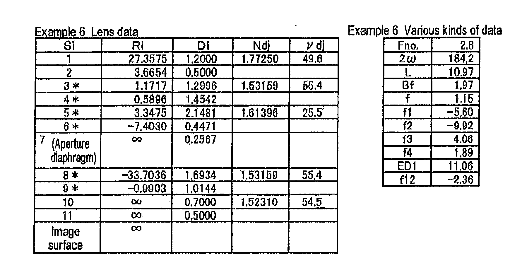
[Table 17] Example 6 Aspheric data Si 3 4 5 6 8 9 KA 00000000E+00 0.0000000E+00 0.0000000E+00 0.0000000E+00 0.0000000E+00 0.0000000E+00 RB3 -4.0953159E-02 -2.0178150E-01 1.9109533E-02 4.3275126E-02 -4.1613423E-02 4.6387660E-02 RB4 -1.4790778E-02 3.3303663E-02 1.0028105E-02 1.4663478E-02 5.9086093E-01 -1.4817687E-01 RB5 -1.3552294E-03 -2.1187973E-02 4.9200289E-03 -3.7344021E-02 -3.8001941E+00 2.0195090E-01 RB6 -6.3451876E-05 2.8741708E-03 -1.5863512E-03 1.5370203E-02 8.6625532E+00 -1.2570203E-01 RB7 3.9324498E-05 2.1157673E-03 3.3561648E-03 2.3716395E-02 -1.7546999E+00 -5.0234005E-02 RB8 2.8184666E-05 6.3059598E-04 1.6704051E-03 -3.3166992E-03 -1.4056574E+01 1.0603458E-02 RB9 7.2379741E-06 5.9935815E-05 -1.3794641E-03 -2.3364161E-02 -1.5094855E+01 Z-0741478E-fl2 RB10 1.4126093E-06 -3.2145192E-05 -9.7219046E-04 -1.3156744E-02 3.4901444E+01 9.7212843E-03 RB11 2.0293542E-07 -2.2081321E-05 5.1417691E-04 2.2126927E-02 7.4660708E+01 -1.4054684E-03 RB12 -1.89744001E-08 3.6348434E-06 2.0120976E-04 1.7303542E-02 -4.1688716E+01 -3-4215411E-03 RB13 -4.1848862E-09 -5295389E-08 6.7285240E-06 -1.9415190E-02 -1.3891012E+02 -2.7166858E-03 RB14 -1.9983127E-09 -3.2832096E-06 -3.0073846E-05 -5.8095409E-03 -5.4903532E+01 -1.2349146E-03 RB15 -8.5124512E-10 -1.8831484E-06 -1.7753657E-05 9.3983617E-03 9.7566467E+01 -1.1667944E-04 RB16 -2.6709409E-10 -8.0860436E-07 -3.4937903E-06 -2.0904873E-03 -1.0655720E+02 3.2375465E-04 RB17 -8.6851956E-11 4.6530851E-08 9.2590396E-07 -4.3670514E-04 7.6715838E+02 4.1523659E-04 RB18 -2.1651724E-11 2.1492315E-07 1.2663412E-06 1.0542780E-03 -9.8293759E+01 4.6769627E-04 RB19 -5.2186011E-12 1.4818404E-07 4.7237687E-07 -9.7256556E-04 -1.3344215E+03 6.7183905E-05 RB20 -1.0959849E-12 -5.0899922E-08 -2.2430532E-07 2.9996370E-04 8.3401478E+02 -1.9585141E-04 [Table 18] Example 6 Data related to curvature radius Surface number Effective diameter end Ratio of effective diameter end to center 3 |RX3| 8.24 |RX3| / |R3| 7.03 4 |RX4| 2.26 |RX4| / |R4| 3.83 5 |RX5| 2.18 |RX5| / |R5| 0.65 6 |RX6| 60.33 |RX6| / |R6| 8.15 8 |RX8| 6.77 |RX8| / |R8| 0.20 9 |RX9| 1.55 |RX9| / |R9| 1.57 
[Table 20] Example 7 Aspheric data Si 3 4 5 6 8 9 KA 0.0000000E+00 0.0000000E+00 0.0000000E+00 0.0000000E+00 0.0000000E+00 0.0000000E+00 RB3 -4.12004B2E-02 -2.0556153E-01 2.2319989E-02 4.4042773E-02 -4.3672286E-D2 4.2814393E-02 RB4 -1.5771092E-02 3.3759829E-02 8.9006866E-03 1.5123805E-02 5.9218335E-01 -1.4637281E-01 RB5 -1.46075B1E-03 -2.1215700E-02 4.7847396E-03 -3.8218576E-02 -3.8020411E+00 2.6175698E-01 RB6 -6.4320966E-05 2.84598166E-03 -1.5773319E-03 1.5603200E-02 8.6615070E+00 -1.2598455-01 R87 4.2583291E-05 2.1046068E-03 3.3754431E-03 2.3932692E-02 -1.7548843E+00 -5.0373393E-02 RB8 2.9358087E-05 6.2707493E-04 1.6865274E-03 -3.2408843E-03 -1.4056598E+01 1.0549841E-02 RB9 7.5359609E-06 5.8949827E-05 -1.3756077E-03 -2.3357565E-02 -1.5094842E+01 2.0723275E-02 RB10 1.4873662E-06 -3.2396450E-05 -9.7095610E-04 -1.3165702E-02 3.4961453E+01 9.7155742E-03 RB11 2.1664369E-07 -2.2139418E-05 5.1452746E-04 2.2118231E-02 7.4660712E+01 -1.4071651E-03 RB12 -1.7045759E-08 3.6229053E-06 2.0130024E-04 1.7298663E-02 -4.1688715E+01 -3.4220260E-03 RB13 -4.0943971-09 -5.2973748E-06 5.7498852E-06 -1.417463E-02 -1.3891012E+02 -2.7168005E-03 RB14 -2.0697899E-09 -3.2833866E-06 -3.0069275E-05 -5.8104902E-03 -5.4903532E+01 -1.2349514E-03 RB15 -8.9033651E-10 -1.8830974E-06 -1.7752803E-05 0.3979939E-03 9.7566167E+01 -1.168934E-04 RB16 -2.8139482E-10 -8.0856500E-07 -3.4936682E-06 -2.0906021E-03 -1.0856720E+02 3.2375201E-04 RB17 -9.1361050E-11 4.6547786E-08 9.2590832E-07 -4.3675249E-04 7.6715938E+02 4.1523589E-04 RB18 -2.2949425E-11 2.1492020E-07 1.2663353E-06 1.0542620E-03 -9.8293759E+01 4.6769609E-04 RB19 -5.5728307E-12 1.4818600E-07 4.7237368E-07 -9.7257085E-04 -1.3344215E+03 6.7183855E-05 RB20 -1.1888733E-12 -5.0899323E-08 -2.2430659E-07 2.9996370E-04 8.3401478E+02 -1.9585142E-04 [Table 21] Example 7 Data related to curvature radius Surface number Effective diameter end Ratio of effective diameter end to center 3 |RX3| 8.78 |RX3| / |R3| 7.64 4 |RX4| 2.30 |RX4| / |R4| 3.87 5 |RX5| 2.19 |RX5| / |R5| 0.61 6 |RX6| 64.10 |RX6| / |R6| 9.05 8 |RX8| 6.25 |RX8| / |R8| 0.23 9 |RX9| 1.54 |RX9| / |R9| 1.56 
[Table 23] Example 8 Aspheric data Si 3 4 5 6 8 9 KA 0.0000000E+00 0.0000000E+00 0.0000000E+00 0.0000003E+00 0.0000000E+00 0.0000000E+00 RB3 -3.5985040E-02 -2.2019139E-01 -5.4697732E-03 4.2031089E-02 -3.8059449E-02 4.0992522E-02 RB4 -1.6281238E-02 3.0417692E-02 1.6821579E-02 2.4011959E-02 5.8932137E-01 -1.4969620E-01 RB5 -1.6075824E-03 -2.1717098E-02 5.8481380E-03 -3.8010208E-02 -37989737E+00 2.6035047E-01 RB6 -9.5489804E-05 2.7954770E-03 -1.5682298E-03 1.4755709E-02 8.6636790E+00 -1.2644322E-01 RB7 3.7102395E-05 2.1046851E-03 3.3306590E-03 2.3484757E-02 -1.7539424E+00 -5.0535684E-02 RB8 2.8616410E-05 6.2899646E-04 1.6676891E-03 -3.4046344E-03 -1.4056264E+01 1.0490387E-02 RB9 7.4976810E-06 5.9681670E-05 -1.3814259E-03 -2.3407590E-02 -1.5094733E+01 2.0702189E-02 RB10 1.5095432E-06 -3.2187008E-05 -9.7254668E-04 -1.3178825E-02 3.4961486E+01 9.7084855E-03 RB11 2.2867768E-07 -2.2086056E-05 5.1411884E-04 2.2115455E-02 7.4660722E+01 -1.4094296E-03 RB12 -1.2770563E-08 3.6358108E-06 2.0119859E-04 1.7298337E-02 -4.1688712E+01 -3.4227192E-03 RB13 -2.7902790E-09 -5.2943348E-06 5.7249437E-06 -1.9417369E-02 -1.3891012E+02 -2.7170057E-03 RB14 -1.7028669E-09 -3.28267706E-06 -3.0075400E-05 -5.8103953E-03 -5.4903532E+01 -1.2350105E-03 RB15 -7.9223903E-10 -1.8820249E-06 -1.7754327E-05 0.3980439E-03 9.7566467E+01 -1.1676601E-04 RB16 -2.5609987E-10 -8.0852166E-07 -3.4940554E-06 -2.0905806E-03 -1.0856720E+02 3.2374738E-04 RB17 -8,5021409E-11 4.6559269E-08 9.2580719E-07 -4.3674411E-04 7.6715938E+02 4.1523462E-04 RB18 -2.1393959E-11 2.1493241E-07 1.2663081E-06 1.05242650E-03 -9.8293759E+01 4.6769574E-04 RB19 -5.19857 19E-12 1.4818694E-07 4.7236607E-07 -9.7256979E-04 -1.3344215E+03 6.7183763E-05 RB20 -1.1003113E-12 -5.0899042E-08 -2.2430871E-07 2.9996370E-04 8.3401478E+02 -1.9585145E-04 [Table 24] Example 8 Data related to curvature radius Surface number Effective diameter end Ratio of effective diameter end to center 3 |RX3| 35,75 |RX3| / |R3| 28.60 4 |RX4| 2.45 |RX4| / |R4| 4.30 5 |RX5| 2.20 |RX5| / |R5| 0.69 6 |RX6| 83.88 |RX6| / |R6| 11.29 8 |RX8| 6.07 |RX8| / |R8| 0.33 9 |RX9| 1.51 |RX9| / |R9| 1.52 
[Table 26] Example 9 Aspheric data Si 3 4 5 6 8 9 KA 0.0000000E+00 0.0000000E+00 0.0000000E+00 0.0000000E+00 0.00000000E+00 0.0000000E+00 RB3 -6.5598440E-02 -2.4523923E-01 1.7837326E-02 2.8651748E-02 -2.2670089E-02 3.6818240E-02 RB4 -1.9260381E-02 2.8745665E-02 3.8871738E-03 2.6903008E-02 5.9556641E-01 -1.4391035E-01 RB5 -1.9127954E-03 -2.2084511E-02 3.8248109E-03 -3.3403150E-02 -3.7991024E+00 2.6278562E-01 RB6 -1.1896934E-04 2.6203142E-03 -1.7189052E-03 1.7052792E-02 8.6631693E+00 -1.2572886E-01 RB7 3.7845566E-05 2.0501827E-03 3.3561676E-03 2.4241346E-02 -1.7541379E+00 -5.0369565E-02 RB8 2.9180626E-03 6.1260762E-04 1.6888191E-03 -3.2288554E-03 -1.4056317E+01 1.0522382E-02 RB9 7.6904173E-06 5.5113398E-05 -1.3738852E-03 -2.3399522E-02 -1.6094745E+01 2.0706636E-02 RB10 1.5370870E-06 -3.3396114E-05 -9.7034070E-04 -1.3197446E-02 3.4961484E+01 9.7085082E-03 RB11 2.2823894E-07 -2-2388850E-05 5.1469793E-04 2.2101574E-02 7.4660721E+01 -1.4097280E-03 RB12 -1.5163482E-08 3.5642338E-06 2.0133918E-04 1.7291229E-02 -4.1688712E+01 -3.4228742E-03 RB13 -3.9576533E-09 -5.3113650E-06 5,756726E-06 -1.9420470E-02 -1.3891012E+02 -2.7170650E-03 RB14 -2.0710134E-09 -3.2866466E-06 -3.0068767E-05 -5.8116253E-03 -5.4903532E+01 -1.2350305E-03 RB15 -9.0451782E-10 -1.8838399E-06 -1.7753092E-05 9.3975873E-03 9.7566467E+01 -1.1671228E-04 RB16 -2.8788754E -8.0873014E-07 -3.4938712E-06 -2.0907417E-03 -1.0855720E+02 3.2374550E-04 RB17 -9.3691191E-11 4.6511994E-08 9.2581828E-07 -4.3679877E-04 7.6715938E+02 4.1523407E-04 RB18 -2.3605268E-11 2.1492167E-07 1.2663014E-06 1.0542471E-03 -9.8293759E+01 4.6769559E-04 RB19 -5.7542139E-12 1.4818447E-07 4.7236183E-07 -9.7257650E-04 -1.3344215E+03 6.7183720E-05 R820 -1.2365358E-12 -5.0899620E-08 -2.2431046E-07 2.9996370E-04 8.3401478E+02 -1.9585146E-04 [Table 27] Example 9 Data related to curvature radius Surface number Effective diameter end Ratio of effective diameter end to center 3 |RX3| 7.69 |RX3| / |R3| 5.76 4 |RX4| 3.53 |RX4| / |R4| 5.17 5 |RX5| 2.18 |RX5| / |R5| 0.79 6 |RX6| 11.15 |RX6| / |R6| 2.87 8 |RX8| 3.12 |RX8| / |R8| 0.80 9 |RX9| 1.60 |RX9| / |R9| 1.48 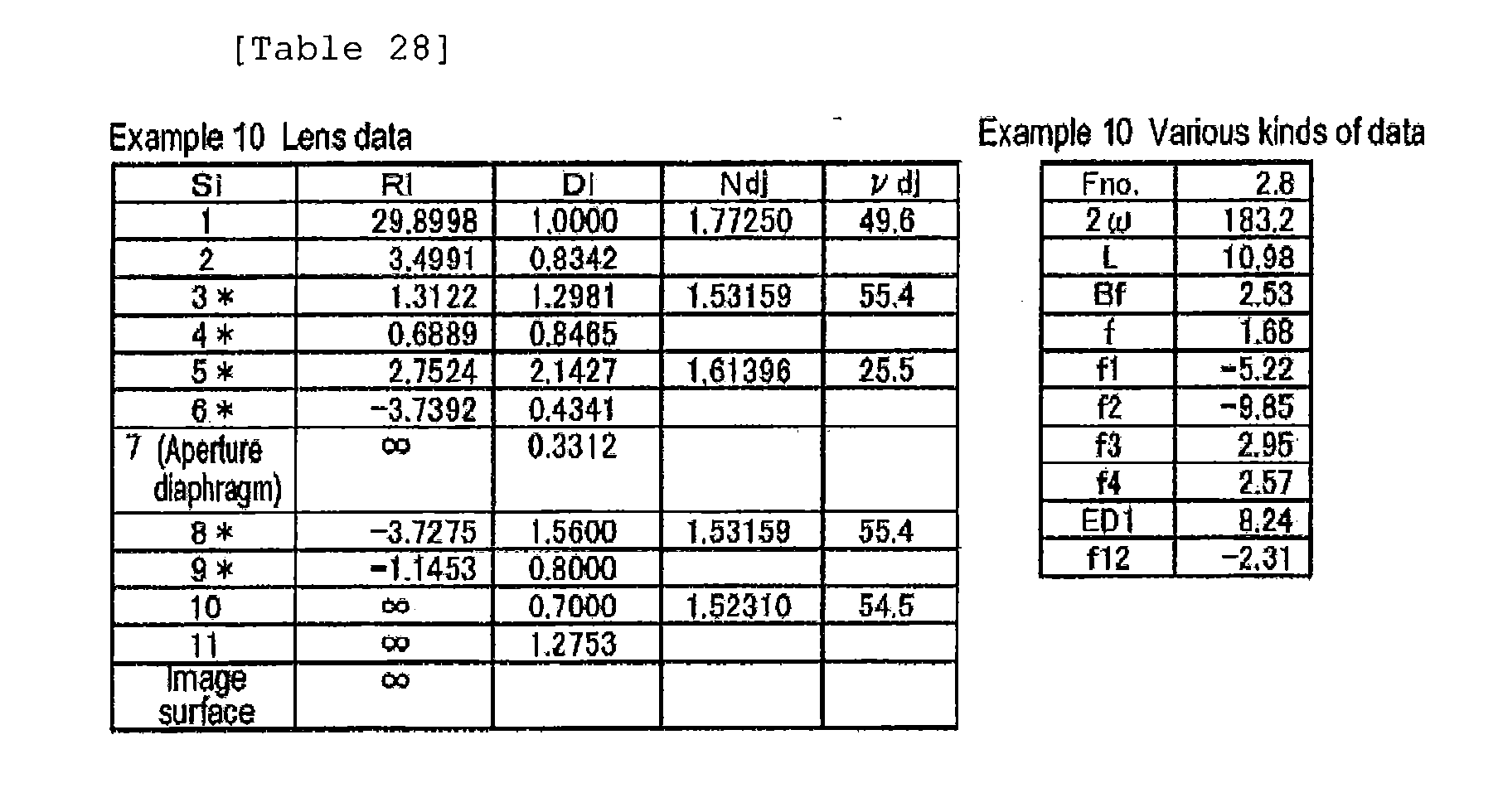
[Table 29] Example 10 Aspheric data Si 3 4 5 6 8 9 KA 0.0000000E+00 0.0000000E+00 0.0000000E+00 0.0000000E+00 0.0000000E+00 0.0000000E+00 RB3 -8.8213576E-02 -2.5077078E-01 1.3102727E-02 2.6302052E-02 -3.3211719E-02 2.2121954E-02 RB4 -1.9700354E-02 2.8339731E-02 4.2916937E-04 2.6344774E-02 5.9644509E-01 -1.4971053E-01 RB5 -1.9694160E-03 -2.2099581E-02 3.4024173E-03 -3.2853427E-02 -3.7972439E+00 2.6167718E-01 RB6 -1.3072386E-04 2.6151162E-03 -1.7091648E-03 1.7581496E-02 8.6639685E+00 -1.2586887E-01 RB7 3.6417540E-05 2.0463532E-03 3.3759135E-03 2.4536232E-02 -1.7638969E+00 -5.0378436E-02 RB8 2.9054724E-05 6.1240669E-04 1.6955625E-03 -3.09560062-03 -1.4056253E+01 1.0522957E-02 RB9 7.6841422E-08 5.5225233E-05 -1.3722038E-03 -2.3345753E-02 -1.5094730E+01 2.0706573E-02 RB10 1.539761E-06 -3.3311180E-05 -9.6999045E-04 -1.3177249E-02 3.4961488E+01 9.7082682E-03 RB11 2.2910436E-07 -2.2351664E-05 5.1475903E-04 2.2108787E-02 7.4660722E+01 -1.4098721E-03 RB12 -1.4988027E-08 3.5775102E-06 2.0134700E-04 1.7293708E-02 -4.1688712E+01 -3.4229349349E-03 RB13 -3.8201450E-09 -5.3071294E-08 5.7668163E-06 -1.9419644E-02 -1.3891012E+02 -2.7170866E-03 RB14 -2.0645786E-09 -3.2853864E-06 -3.0069181E-05 -5.8113572E-03 -5.4903532E+01 -1.2350374E-03 RB15 -9.0352162E-10 -1.8834838E-06 -1.7753293E-05 9.3976725E-03 9.7566467E+01 -1.1671437E-04 RB16 -2.8775171E-10 -8.0863280E-07 -3.4939430E-06 -2.0907162E-03 -1.0855720E+02 3.2374490E-04 RB17 -9.3676208E-11 4.6537922E-08 9.2576578E-07 -4.3679065E-04 7.6715938E+02 4.1523391E-04 RB18 -2.3604458E-11 2.1492844E-07 1.2662948E-06 1.0542495E-03 -9.8293759E+01 4.6769554E-04 RB19 -5.7544264E-12 1.4818621E-07 4.7235998E-07 -9.7257478E-04 -1.3344215E+03 6.7183708E-05 RB20 -1.2366382E-12 -5.0899177E-08 -2.2431096E-07 2.9996370E-04 8.3401478E+02 -1.9585146E-04 [Table 30] Example 10 Data related to curvature radius Surface number Effective diameter end Ratio of effective diameter end to center 3 |RX3| 6.91 |RX3| / |R3| 5.27 4 |RX4| 4.28 |RX4| / |R4| 6.22 5 |RX5| 2.28 |RX5| / |R5| 0.83 6 |RX6| 10.76 |RX6| / |R6| 2.88 8 |HX8| 2.91 |RX8| / |R8| 0.78 9 |RX9| 1.55 |RX9| / |R9| 1.36 

[Table 32] Example 11 Aspheric data Si 3 4 5 6 8 9 KA -7.9943716E+00 2.7728200E-02 -1.5389922E+02 -1.4940743E+01 0.0000000E+00 8.3414600E-02 RB3 -3.4550440E-03 -1.0021478E-02 1.0300373E-01 8.9430489E-03 -5.6743121E-02 -3.0199577E-03 RB4 -8.5283513E-04 -4.3440364E-03 -1.5255671E-02 6.7993179E-03 -1.2952674E-02 1.6377891E-02 RB5 1.1019453E-03 7.1649734-04 1.9699772E-03 6.0006696E-04 -4.6414993E-03 -9.2047265E-04 RB6 -8.4652828E-04 3.1234970E-04 6.22856B0E-04 -3.0179310E-04 -1.7142958E-03 -1.4646213E-03 RB7 2.4837945E-04 1.9165842-03 -3.3708230E-05 -1.5785908E-03 2.1454934E-03 -5.8647989E-04 RB8 -8.1565649E-05 3.3949277E-05 1.5081634-04 -5.1453526E-04 2.5740702E-03 -3.7049696E-04 RB9 6.0456206E-05 5.3847066E-04 -4.1597497E-05 -3.6579799E-04 1.0343849E-03 4.7524364E-04 RB10 -1.55121763E-05 -5.1102181E-04 2.7968405E-05 -1.9409237E-04 1.4782091E-03 -3.0122214E-04 RB11 -4.0181829E-06 -1.9673650E-06 4.8464276E-06 -2.2149697E-04 7.1590027E-04 -2.3990942E-05 RB12 1.8644440E-07 3.0374012E-07 -1.0254003E-06 -1.5811221E-04 -6,6690609E-05 -4.7531640E-06 RB13 3.8121178E-07 8.7023242E-07 -2.0085599E-06 -1.1598448E-04 -4.5243629E-04 1.3660305E-06 RB14 8.5003204E-08 8.1706254E-07 -1.6086137E-06 -8.4384905E-05 -38886668E-04 2-5517103E-06 RB15 -3.2040992-08 6.0871909E-07 -1.0309911E-06 -2.8906654-05 1.0213544E-04 2.1828784E-06 RB16 -2.6439237E-11 -5.3661039E-09 -1.0230862E-07 2.0878564E-05 -1.5622448E-04 1.4659541E-06 RB17 -7.3853617E-12 -1.1874355E-09 -3.6412125E-08 -8.2152849E-05 7.7434060E-04 7.7040882E-07 RB18 -1.3295168E-12 4.2183360-10 -6.3854374-09 3.1606444E-04 1.6338136E-03 3.0369126E-07 RB19 8.8223706E-14 9.6692323E-10 4.7089709E-09 9.9687344E-05 -1.5350965E-03 2.0192855E-08 RB20 2.4771836E-13 1.0784659E-09 7.1558627E-09 7.7103658E-04 -3.5564150E-04 -1.3450294E-07 [Table 33] Example 11 Data related to curvature radius Surface number Effective diameter end Ratio of effective diameter end to center 3 |RX3| 20.35 |RX3| / |R3| 5.32 4 |RX4| 2.56 |RX4| / |R4| 1.68 5 |RX5| 2.77 |RX5| / |R5| 0.55 6 |RX6| 10.96 |RX6| / |R6| 1.46 8 |RX8| 5.59 |RX8| / |R8| 0.01 9 |RX9| 1.95 |RX9| / |R9| 1.69 - In all of the imaging lenses according to Examples 1 to 11, the first lens L1 is a spherical glass lens. One surface or both surfaces of the first lens L1 may be aspheric surfaces. When the first lens L1 is an aspheric glass lens, it is possible to effectively correct all aberrations.
- In the imaging lenses according to Examples 1 to 11, the second lens L2, the third lens L3, and the fourth lens L4 are all made of plastic. Therefore, it is possible to manufacture inexpensive lenses with a light weight.
- Table 34 shows values corresponding to
Conditional expressions 1 to 15 of the imaging lenses according to Examples 1 to 11. In Examples 1 to 11, the d-line is a reference wavelength, and Table 34 shows each value at the reference wavelength. As can be seen from Table 34, all of Examples 1 to 8 satisfyConditional expressions 1 to 15.

-
Figs. 13A to 13I ,Figs. 14A to 14I ,Figs. 15A to 15I ,Figs. 16A to 16I ,Figs. 17A to 17I ,Figs. 18A to 18I ,Figs. 19A to 19I ,Figs. 20A to 20I ,Figs. 21A to 21I ,Figs. 22A to 22I , andFigs. 23A to 23I are aberration diagrams illustrating the spherical aberration, astigmatism, distortion, lateral chromatic aberration, and lateral aberration of the imaging lenses according to Examples 1 to 11. - The aberration diagrams according to Example 1 will be described below as an example, which is the same with the aberration diagrams according to the other examples.
Fig. 13A, Fig. 13B, Fig. 13C, and Fig. 13D are aberration diagrams respectively illustrating the spherical aberration, astigmatism, distortion, and lateral chromatic aberration of the imaging lens according to Example 1,Figs. 13E to 13G are aberration diagrams illustrating lateral aberration in the tangential direction at each angle of view, andFigs. 13H to 13I are aberration diagrams illustrating lateral aberration in the sagittal direction at each angle of view. - In the spherical aberration diagram, Fno. means the F number. In the other aberration diagrams, ω means a half angle of view. The distortion diagram shows the amount of deviation from an ideal image height f × tan(φ) (where f indicates the focal length of the entire system and φ indicates an angle of view (which is treated as a variable; 0 ≤ φ ≤ ω). Each of the aberration diagrams shows aberration in the tangential direction and the sagittal direction at each half angle of view so as to be aligned with the horizontal direction. Since lateral aberration in the tangential direction and lateral aberration in the sagittal direction are equal to each other on the optical axis where ω is 0°, a diagram illustrating lateral aberration in the sagittal direction on the optical axis is omitted. Each aberration diagram shows aberration with respect to the d-line (587.56 nm), which is the reference wavelength. However, the spherical aberration diagram and the lateral chromatic aberration diagram also show aberrations with respect to the F-line (wavelength: 486.13 nm) and the C-line (wavelength: 656.27 nm).
- As can be seen from the above-mentioned data, each of the imaging lenses according to Examples 1 to 11 includes a small number of lenses, for example, four lenses, a small size, a low manufacturing cost, a small F number of 2.0 to 2.8, and a total angle of view of 149° to 184°, which is a wide angle of view. In addition, in the imaging lenses, the effective diameter of the object-side surface of the first lens L1 is equal to or less than 12 mm and a small portion is exposed to the outside. All aberrations of the imaging lenses are effectively corrected and the imaging lenses have good optical performances. The imaging lenses can be appropriately applied to, for example, monitoring cameras or in-vehicle cameras for capturing the images of the front, side and rear of the vehicle.
-
Fig. 18 shows an example in which an imaging apparatus including the imaging lens according to this embodiment is provided in avehicle 100. InFig. 18 , thevehicle 100 includes an outside-vehicle camera 101 for capturing the image of a blind spot area of the passenger seat side, an outside-vehicle camera 102 for capturing the image of a blind spot area of the rear side of thevehicle 100, and an in-vehicle camera 103 that is attached to the rear surface of a room mirror and captures the same visual field range as that of a driver. The outside-vehicle camera 101, the outside-vehicle camera 102, and the in-vehicle camera 103 are the imaging apparatuses according to the embodiment of the invention, and include the imagine lens according to the embodiment of the invention and an imaging device that converts an optical image formed by the imaging lens into an electric signal. - Since the imaging lens according to the embodiment of the invention has the above-mentioned advantages, the outside-
vehicle cameras vehicle camera 103 do not deteriorate the appearance of the vehicle, have a small size, a low manufacturing cost, a wide angle of view, and can obtain high-quality images. - The embodiments and examples of the invention have been described above, but the invention is not limited to the embodiments and examples. Various modifications and changes of the invention can be made. For example, the curvature radius, surface spacing, refractive index, Abbe number, and aspheric coefficient of each lens component are not limited to the values described in each numerical example, but may have other values.
- In the above-described embodiment of the invention, the imaging apparatus is applied to the in-vehicle camera, but the purpose of the invention is not limited thereto. For example, the invention can be applied to cameras for portable terminals or monitoring cameras.
Claims (11)
- An imaging lens comprising:a first negative lens having a meniscus shape in which a concave surface faces an image side;a second negative lens having a meniscus shape in which a concave surface faces the image side and including at least one aspheric surface;a third positive lens including at least one aspheric surface;a stop; anda fourth positive lens including at least one aspheric surface,wherein the first to fourth lenses are arranged in this order from an object side, andthe imaging lens satisfies the following conditional expression:

where f indicates the focal length of the entire system and f2 indicates the focal length of the second lens. - An imaging lens comprising:a first negative lens having a meniscus shape in which a concave surface faces an image side;a second negative lens having a meniscus shape in which a concave surface faces the image side and including at least one aspheric surface;a third positive lens including at least one aspheric surface;a stop; anda fourth positive lens including at least one aspheric surface,wherein the first to fourth lenses are arranged in this order from an object side, andthe imaging lens satisfies the following conditional expression:

where ED1 indicates the effective diameter of an object-side surface of the first lens and D1 indicates the thickness of the center of the first lens. - The imaging lens according to claim 1 or 2,
wherein an object-side surface of the second lens is configured such that an effective diameter edge is disposed closer to the image side than an intersection point between the object-side surface and an optical axis, and
the imaging lens satisfies the following conditional expression:
where DX3 indicates the distance between an intersection point between the optical axis and a perpendicular line that drops from the effective diameter edge to the optical axis and the center of the object-side surface in an optical axis direction. - The imaging lens according to any one of claims 1 to 3,
wherein the imaging lens satisfies the following conditional expression:
where f indicates the focal length of the entire system and RX3 indicates the curvature radius of the object-side surface of the second lens at the effective diameter edge. - The imaging lens according to any one of claims 1 to 4,
wherein the imaging lens satisfies the following conditional expression:
where f indicates the focal length of the entire system and R3 indicates the curvature radius of the object-side surface of the second lens at the center. - The imaging lens according to any one of claims 1 to 5,
wherein the imaging lens satisfies the following conditional expression:
where f indicates the focal length of the entire system and L indicates the distance from the object-side surface of the first lens to an image plane in the optical axis direction. - The imaging lens according to any one of claims 1 to 6,
wherein the imaging lens satisfies the following conditional expression:
where f indicates the focal length of the entire system and f1 indicates the focal length of the first lens. - The imaging lens according to any one of claims 1 to 7,
wherein the imaging lens satisfies the following conditional expression:
where f indicates the focal length of the entire system and D2 indicates an air space between the first lens and the second lens on the optical axis. - The imaging lens according to any one of claims 1 to 8,
wherein the imaging lens satisfies the following conditional expression:
where f indicates the focal length of the entire system and f12 indicates a composite focal length of the first lens and the second lens. - The imaging lens according to any one of claims 1 to 9,
wherein the imaging lens satisfies the following conditional expression:
where f indicates the focal length of the entire system and R1 indicates the curvature radius of the object-side surface of the first lens. - An imaging apparatus comprising the imaging lens according to any one of claims 1 to 10.
Applications Claiming Priority (2)
| Application Number | Priority Date | Filing Date | Title |
|---|---|---|---|
| JP2009175986 | 2009-07-29 | ||
| JP2010126631A JP5486408B2 (en) | 2009-07-29 | 2010-06-02 | Imaging lens and imaging apparatus |
Publications (3)
| Publication Number | Publication Date |
|---|---|
| EP2280302A2 true EP2280302A2 (en) | 2011-02-02 |
| EP2280302A3 EP2280302A3 (en) | 2011-11-02 |
| EP2280302B1 EP2280302B1 (en) | 2013-11-20 |
Family
ID=43216215
Family Applications (1)
| Application Number | Title | Priority Date | Filing Date |
|---|---|---|---|
| EP10171079.6A Not-in-force EP2280302B1 (en) | 2009-07-29 | 2010-07-28 | Imaging lens and imaging apparatus |
Country Status (3)
| Country | Link |
|---|---|
| US (1) | US8314998B2 (en) |
| EP (1) | EP2280302B1 (en) |
| JP (1) | JP5486408B2 (en) |
Families Citing this family (6)
| Publication number | Priority date | Publication date | Assignee | Title |
|---|---|---|---|---|
| JP5399306B2 (en) * | 2009-04-10 | 2014-01-29 | 富士フイルム株式会社 | Imaging lens and imaging apparatus |
| JPWO2014203720A1 (en) * | 2013-06-20 | 2017-02-23 | コニカミノルタ株式会社 | Imaging lens and imaging apparatus |
| CN107121762B (en) * | 2017-06-30 | 2023-09-08 | 中山市众盈光学有限公司 | Vehicle-mounted lens optical system |
| JP6830469B2 (en) * | 2017-11-20 | 2021-02-17 | 富士フイルム株式会社 | Imaging optics, projection display, and imaging equipment |
| JP7621799B2 (en) * | 2021-01-04 | 2025-01-27 | マクセル株式会社 | Imaging lens system and imaging device |
| CN112731632A (en) * | 2021-01-20 | 2021-04-30 | 湖北华鑫光电有限公司 | 4P large-visual-angle large-relative-illumination lens |
Citations (4)
| Publication number | Priority date | Publication date | Assignee | Title |
|---|---|---|---|---|
| JP2002244031A (en) | 2001-02-21 | 2002-08-28 | Nagano Kogaku Kenkyusho:Kk | Wide-angle lens |
| JP2005227426A (en) | 2004-02-12 | 2005-08-25 | Nagano Kogaku Kenkyusho:Kk | Wide angle lens |
| JP2006259704A (en) | 2005-02-21 | 2006-09-28 | Fujinon Corp | Wide-angle imaging lens |
| JP2007206516A (en) | 2006-02-03 | 2007-08-16 | Enplas Corp | Imaging lens |
Family Cites Families (10)
| Publication number | Priority date | Publication date | Assignee | Title |
|---|---|---|---|---|
| JPH11305125A (en) * | 1998-02-19 | 1999-11-05 | Canon Inc | Zoom lens and photographing apparatus using the same |
| JP4747645B2 (en) * | 2005-04-11 | 2011-08-17 | コニカミノルタオプト株式会社 | Wide angle lens and imaging device |
| JP4744184B2 (en) * | 2005-04-20 | 2011-08-10 | 日本電産コパル株式会社 | Super wide angle lens |
| JP4994262B2 (en) | 2007-03-30 | 2012-08-08 | リコー光学株式会社 | Wide angle lens and photographing device |
| JP5084335B2 (en) * | 2007-04-16 | 2012-11-28 | 京セラ株式会社 | Imaging lens |
| JP2008281859A (en) * | 2007-05-11 | 2008-11-20 | Largan Precision Co Ltd | Wide angle lens |
| JP5252842B2 (en) * | 2007-06-27 | 2013-07-31 | 京セラ株式会社 | Imaging lens |
| JP5065159B2 (en) * | 2007-07-05 | 2012-10-31 | 富士フイルム株式会社 | Imaging lens and imaging apparatus |
| JP2010014855A (en) * | 2008-07-02 | 2010-01-21 | Fujinon Corp | Imaging lens and imaging apparatus |
| JP2010107611A (en) * | 2008-10-29 | 2010-05-13 | Olympus Imaging Corp | Imaging optical system and imaging apparatus using the same |
-
2010
- 2010-06-02 JP JP2010126631A patent/JP5486408B2/en not_active Expired - Fee Related
- 2010-07-28 US US12/845,379 patent/US8314998B2/en not_active Expired - Fee Related
- 2010-07-28 EP EP10171079.6A patent/EP2280302B1/en not_active Not-in-force
Patent Citations (4)
| Publication number | Priority date | Publication date | Assignee | Title |
|---|---|---|---|---|
| JP2002244031A (en) | 2001-02-21 | 2002-08-28 | Nagano Kogaku Kenkyusho:Kk | Wide-angle lens |
| JP2005227426A (en) | 2004-02-12 | 2005-08-25 | Nagano Kogaku Kenkyusho:Kk | Wide angle lens |
| JP2006259704A (en) | 2005-02-21 | 2006-09-28 | Fujinon Corp | Wide-angle imaging lens |
| JP2007206516A (en) | 2006-02-03 | 2007-08-16 | Enplas Corp | Imaging lens |
Also Published As
| Publication number | Publication date |
|---|---|
| JP2011048334A (en) | 2011-03-10 |
| US8314998B2 (en) | 2012-11-20 |
| US20110026138A1 (en) | 2011-02-03 |
| EP2280302A3 (en) | 2011-11-02 |
| EP2280302B1 (en) | 2013-11-20 |
| JP5486408B2 (en) | 2014-05-07 |
Similar Documents
| Publication | Publication Date | Title |
|---|---|---|
| CN201716460U (en) | Camera lens and camera device | |
| JP5462466B2 (en) | Imaging lens and imaging apparatus | |
| US8508862B2 (en) | Image pickup lens and image pickup apparatus | |
| CN201689210U (en) | Camera shooting lens and camera shooting device | |
| US8144405B2 (en) | Imaging lens and imaging apparatus | |
| CN201716459U (en) | Shooting lens and shooting device | |
| CN201707490U (en) | Pickup lens and pickup device | |
| CN104914554B (en) | Imaging lens system and photographic device | |
| CN201837767U (en) | Shooting lens and shooting device | |
| US20110249349A1 (en) | Image pickup lens and image pickup apparatus | |
| CN106094170A (en) | Imaging lens system and camera head | |
| EP2642325B1 (en) | Image pickup lens and image pickup device | |
| CN104914553A (en) | Imaging lens and imaging apparatus | |
| EP2280302B1 (en) | Imaging lens and imaging apparatus | |
| JP5313566B2 (en) | Imaging lens and imaging apparatus using the same | |
| CN104914552B (en) | Imaging lens system and photographic device | |
| CN104220917B (en) | Imaging lens system and camera head | |
| JP5113001B2 (en) | Wide-angle imaging lens and imaging device | |
| CN112835185B (en) | Optical system, camera module, electronic equipment and automobile | |
| JP5474668B2 (en) | Imaging lens and imaging apparatus | |
| TWM368071U (en) | Photographing lens and photographing device |
Legal Events
| Date | Code | Title | Description |
|---|---|---|---|
| PUAI | Public reference made under article 153(3) epc to a published international application that has entered the european phase |
Free format text: ORIGINAL CODE: 0009012 |
|
| AK | Designated contracting states |
Kind code of ref document: A2 Designated state(s): AL AT BE BG CH CY CZ DE DK EE ES FI FR GB GR HR HU IE IS IT LI LT LU LV MC MK MT NL NO PL PT RO SE SI SK SM TR |
|
| AX | Request for extension of the european patent |
Extension state: BA ME RS |
|
| PUAL | Search report despatched |
Free format text: ORIGINAL CODE: 0009013 |
|
| RIC1 | Information provided on ipc code assigned before grant |
Ipc: G02B 13/06 20060101ALI20110916BHEP Ipc: G02B 9/34 20060101AFI20110916BHEP Ipc: G02B 13/00 20060101ALI20110916BHEP |
|
| AK | Designated contracting states |
Kind code of ref document: A3 Designated state(s): AL AT BE BG CH CY CZ DE DK EE ES FI FR GB GR HR HU IE IS IT LI LT LU LV MC MK MT NL NO PL PT RO SE SI SK SM TR |
|
| AX | Request for extension of the european patent |
Extension state: BA ME RS |
|
| 17P | Request for examination filed |
Effective date: 20120426 |
|
| GRAP | Despatch of communication of intention to grant a patent |
Free format text: ORIGINAL CODE: EPIDOSNIGR1 |
|
| INTG | Intention to grant announced |
Effective date: 20130607 |
|
| GRAS | Grant fee paid |
Free format text: ORIGINAL CODE: EPIDOSNIGR3 |
|
| GRAA | (expected) grant |
Free format text: ORIGINAL CODE: 0009210 |
|
| AK | Designated contracting states |
Kind code of ref document: B1 Designated state(s): AL AT BE BG CH CY CZ DE DK EE ES FI FR GB GR HR HU IE IS IT LI LT LU LV MC MK MT NL NO PL PT RO SE SI SK SM TR |
|
| REG | Reference to a national code |
Ref country code: GB Ref legal event code: FG4D |
|
| REG | Reference to a national code |
Ref country code: CH Ref legal event code: EP |
|
| REG | Reference to a national code |
Ref country code: AT Ref legal event code: REF Ref document number: 641971 Country of ref document: AT Kind code of ref document: T Effective date: 20131215 |
|
| REG | Reference to a national code |
Ref country code: IE Ref legal event code: FG4D |
|
| REG | Reference to a national code |
Ref country code: DE Ref legal event code: R096 Ref document number: 602010011830 Country of ref document: DE Effective date: 20140116 |
|
| REG | Reference to a national code |
Ref country code: NL Ref legal event code: VDEP Effective date: 20131120 |
|
| REG | Reference to a national code |
Ref country code: AT Ref legal event code: MK05 Ref document number: 641971 Country of ref document: AT Kind code of ref document: T Effective date: 20131120 |
|
| REG | Reference to a national code |
Ref country code: LT Ref legal event code: MG4D |
|
| PG25 | Lapsed in a contracting state [announced via postgrant information from national office to epo] |
Ref country code: IS Free format text: LAPSE BECAUSE OF FAILURE TO SUBMIT A TRANSLATION OF THE DESCRIPTION OR TO PAY THE FEE WITHIN THE PRESCRIBED TIME-LIMIT Effective date: 20140320 Ref country code: LT Free format text: LAPSE BECAUSE OF FAILURE TO SUBMIT A TRANSLATION OF THE DESCRIPTION OR TO PAY THE FEE WITHIN THE PRESCRIBED TIME-LIMIT Effective date: 20131120 Ref country code: FI Free format text: LAPSE BECAUSE OF FAILURE TO SUBMIT A TRANSLATION OF THE DESCRIPTION OR TO PAY THE FEE WITHIN THE PRESCRIBED TIME-LIMIT Effective date: 20131120 Ref country code: HR Free format text: LAPSE BECAUSE OF FAILURE TO SUBMIT A TRANSLATION OF THE DESCRIPTION OR TO PAY THE FEE WITHIN THE PRESCRIBED TIME-LIMIT Effective date: 20131120 Ref country code: NO Free format text: LAPSE BECAUSE OF FAILURE TO SUBMIT A TRANSLATION OF THE DESCRIPTION OR TO PAY THE FEE WITHIN THE PRESCRIBED TIME-LIMIT Effective date: 20140220 Ref country code: NL Free format text: LAPSE BECAUSE OF FAILURE TO SUBMIT A TRANSLATION OF THE DESCRIPTION OR TO PAY THE FEE WITHIN THE PRESCRIBED TIME-LIMIT Effective date: 20131120 Ref country code: SE Free format text: LAPSE BECAUSE OF FAILURE TO SUBMIT A TRANSLATION OF THE DESCRIPTION OR TO PAY THE FEE WITHIN THE PRESCRIBED TIME-LIMIT Effective date: 20131120 |
|
| PG25 | Lapsed in a contracting state [announced via postgrant information from national office to epo] |
Ref country code: LV Free format text: LAPSE BECAUSE OF FAILURE TO SUBMIT A TRANSLATION OF THE DESCRIPTION OR TO PAY THE FEE WITHIN THE PRESCRIBED TIME-LIMIT Effective date: 20131120 Ref country code: BE Free format text: LAPSE BECAUSE OF FAILURE TO SUBMIT A TRANSLATION OF THE DESCRIPTION OR TO PAY THE FEE WITHIN THE PRESCRIBED TIME-LIMIT Effective date: 20131120 Ref country code: AT Free format text: LAPSE BECAUSE OF FAILURE TO SUBMIT A TRANSLATION OF THE DESCRIPTION OR TO PAY THE FEE WITHIN THE PRESCRIBED TIME-LIMIT Effective date: 20131120 Ref country code: ES Free format text: LAPSE BECAUSE OF FAILURE TO SUBMIT A TRANSLATION OF THE DESCRIPTION OR TO PAY THE FEE WITHIN THE PRESCRIBED TIME-LIMIT Effective date: 20131120 |
|
| PG25 | Lapsed in a contracting state [announced via postgrant information from national office to epo] |
Ref country code: PT Free format text: LAPSE BECAUSE OF FAILURE TO SUBMIT A TRANSLATION OF THE DESCRIPTION OR TO PAY THE FEE WITHIN THE PRESCRIBED TIME-LIMIT Effective date: 20140320 |
|
| PG25 | Lapsed in a contracting state [announced via postgrant information from national office to epo] |
Ref country code: EE Free format text: LAPSE BECAUSE OF FAILURE TO SUBMIT A TRANSLATION OF THE DESCRIPTION OR TO PAY THE FEE WITHIN THE PRESCRIBED TIME-LIMIT Effective date: 20131120 |
|
| REG | Reference to a national code |
Ref country code: DE Ref legal event code: R097 Ref document number: 602010011830 Country of ref document: DE |
|
| PG25 | Lapsed in a contracting state [announced via postgrant information from national office to epo] |
Ref country code: SK Free format text: LAPSE BECAUSE OF FAILURE TO SUBMIT A TRANSLATION OF THE DESCRIPTION OR TO PAY THE FEE WITHIN THE PRESCRIBED TIME-LIMIT Effective date: 20131120 Ref country code: CZ Free format text: LAPSE BECAUSE OF FAILURE TO SUBMIT A TRANSLATION OF THE DESCRIPTION OR TO PAY THE FEE WITHIN THE PRESCRIBED TIME-LIMIT Effective date: 20131120 Ref country code: RO Free format text: LAPSE BECAUSE OF FAILURE TO SUBMIT A TRANSLATION OF THE DESCRIPTION OR TO PAY THE FEE WITHIN THE PRESCRIBED TIME-LIMIT Effective date: 20131120 Ref country code: PL Free format text: LAPSE BECAUSE OF FAILURE TO SUBMIT A TRANSLATION OF THE DESCRIPTION OR TO PAY THE FEE WITHIN THE PRESCRIBED TIME-LIMIT Effective date: 20131120 |
|
| PLBE | No opposition filed within time limit |
Free format text: ORIGINAL CODE: 0009261 |
|
| STAA | Information on the status of an ep patent application or granted ep patent |
Free format text: STATUS: NO OPPOSITION FILED WITHIN TIME LIMIT |
|
| PG25 | Lapsed in a contracting state [announced via postgrant information from national office to epo] |
Ref country code: DK Free format text: LAPSE BECAUSE OF FAILURE TO SUBMIT A TRANSLATION OF THE DESCRIPTION OR TO PAY THE FEE WITHIN THE PRESCRIBED TIME-LIMIT Effective date: 20131120 |
|
| 26N | No opposition filed |
Effective date: 20140821 |
|
| REG | Reference to a national code |
Ref country code: DE Ref legal event code: R097 Ref document number: 602010011830 Country of ref document: DE Effective date: 20140821 |
|
| PG25 | Lapsed in a contracting state [announced via postgrant information from national office to epo] |
Ref country code: LU Free format text: LAPSE BECAUSE OF FAILURE TO SUBMIT A TRANSLATION OF THE DESCRIPTION OR TO PAY THE FEE WITHIN THE PRESCRIBED TIME-LIMIT Effective date: 20140728 Ref country code: SI Free format text: LAPSE BECAUSE OF FAILURE TO SUBMIT A TRANSLATION OF THE DESCRIPTION OR TO PAY THE FEE WITHIN THE PRESCRIBED TIME-LIMIT Effective date: 20131120 |
|
| REG | Reference to a national code |
Ref country code: CH Ref legal event code: PL |
|
| REG | Reference to a national code |
Ref country code: IE Ref legal event code: MM4A |
|
| REG | Reference to a national code |
Ref country code: FR Ref legal event code: ST Effective date: 20150331 |
|
| PG25 | Lapsed in a contracting state [announced via postgrant information from national office to epo] |
Ref country code: LI Free format text: LAPSE BECAUSE OF NON-PAYMENT OF DUE FEES Effective date: 20140731 Ref country code: IT Free format text: LAPSE BECAUSE OF FAILURE TO SUBMIT A TRANSLATION OF THE DESCRIPTION OR TO PAY THE FEE WITHIN THE PRESCRIBED TIME-LIMIT Effective date: 20131120 Ref country code: CH Free format text: LAPSE BECAUSE OF NON-PAYMENT OF DUE FEES Effective date: 20140731 |
|
| PG25 | Lapsed in a contracting state [announced via postgrant information from national office to epo] |
Ref country code: FR Free format text: LAPSE BECAUSE OF NON-PAYMENT OF DUE FEES Effective date: 20140731 |
|
| PG25 | Lapsed in a contracting state [announced via postgrant information from national office to epo] |
Ref country code: IE Free format text: LAPSE BECAUSE OF NON-PAYMENT OF DUE FEES Effective date: 20140728 |
|
| PG25 | Lapsed in a contracting state [announced via postgrant information from national office to epo] |
Ref country code: SM Free format text: LAPSE BECAUSE OF FAILURE TO SUBMIT A TRANSLATION OF THE DESCRIPTION OR TO PAY THE FEE WITHIN THE PRESCRIBED TIME-LIMIT Effective date: 20131120 Ref country code: MC Free format text: LAPSE BECAUSE OF FAILURE TO SUBMIT A TRANSLATION OF THE DESCRIPTION OR TO PAY THE FEE WITHIN THE PRESCRIBED TIME-LIMIT Effective date: 20131120 |
|
| PG25 | Lapsed in a contracting state [announced via postgrant information from national office to epo] |
Ref country code: MT Free format text: LAPSE BECAUSE OF FAILURE TO SUBMIT A TRANSLATION OF THE DESCRIPTION OR TO PAY THE FEE WITHIN THE PRESCRIBED TIME-LIMIT Effective date: 20131120 Ref country code: BG Free format text: LAPSE BECAUSE OF FAILURE TO SUBMIT A TRANSLATION OF THE DESCRIPTION OR TO PAY THE FEE WITHIN THE PRESCRIBED TIME-LIMIT Effective date: 20131120 Ref country code: GR Free format text: LAPSE BECAUSE OF FAILURE TO SUBMIT A TRANSLATION OF THE DESCRIPTION OR TO PAY THE FEE WITHIN THE PRESCRIBED TIME-LIMIT Effective date: 20140221 Ref country code: CY Free format text: LAPSE BECAUSE OF FAILURE TO SUBMIT A TRANSLATION OF THE DESCRIPTION OR TO PAY THE FEE WITHIN THE PRESCRIBED TIME-LIMIT Effective date: 20131120 |
|
| PG25 | Lapsed in a contracting state [announced via postgrant information from national office to epo] |
Ref country code: TR Free format text: LAPSE BECAUSE OF FAILURE TO SUBMIT A TRANSLATION OF THE DESCRIPTION OR TO PAY THE FEE WITHIN THE PRESCRIBED TIME-LIMIT Effective date: 20131120 Ref country code: HU Free format text: LAPSE BECAUSE OF FAILURE TO SUBMIT A TRANSLATION OF THE DESCRIPTION OR TO PAY THE FEE WITHIN THE PRESCRIBED TIME-LIMIT; INVALID AB INITIO Effective date: 20100728 |
|
| REG | Reference to a national code |
Ref country code: DE Ref legal event code: R082 Ref document number: 602010011830 Country of ref document: DE Representative=s name: MANITZ FINSTERWALD PATENT- UND RECHTSANWALTSPA, DE Ref country code: DE Ref legal event code: R082 Ref document number: 602010011830 Country of ref document: DE Representative=s name: KLUNKER IP PATENTANWAELTE PARTG MBB, DE |
|
| PG25 | Lapsed in a contracting state [announced via postgrant information from national office to epo] |
Ref country code: MK Free format text: LAPSE BECAUSE OF FAILURE TO SUBMIT A TRANSLATION OF THE DESCRIPTION OR TO PAY THE FEE WITHIN THE PRESCRIBED TIME-LIMIT Effective date: 20131120 |
|
| PG25 | Lapsed in a contracting state [announced via postgrant information from national office to epo] |
Ref country code: AL Free format text: LAPSE BECAUSE OF FAILURE TO SUBMIT A TRANSLATION OF THE DESCRIPTION OR TO PAY THE FEE WITHIN THE PRESCRIBED TIME-LIMIT Effective date: 20131120 |
|
| REG | Reference to a national code |
Ref country code: DE Ref legal event code: R082 Ref document number: 602010011830 Country of ref document: DE Representative=s name: MANITZ FINSTERWALD PATENT- UND RECHTSANWALTSPA, DE Ref country code: DE Ref legal event code: R081 Ref document number: 602010011830 Country of ref document: DE Owner name: NANCHANG O-FILM OPTICAL-ELECTRONIC TECH CO., L, CN Free format text: FORMER OWNER: FUJIFILM CORPORATION, TOKYO, JP Ref country code: DE Ref legal event code: R081 Ref document number: 602010011830 Country of ref document: DE Owner name: TIANJIN O-FILM OPTO ELECTRONICS CO., LTD., CN Free format text: FORMER OWNER: FUJIFILM CORPORATION, TOKYO, JP |
|
| REG | Reference to a national code |
Ref country code: GB Ref legal event code: 732E Free format text: REGISTERED BETWEEN 20190124 AND 20190130 |
|
| REG | Reference to a national code |
Ref country code: DE Ref legal event code: R082 Ref document number: 602010011830 Country of ref document: DE Representative=s name: MANITZ FINSTERWALD PATENT- UND RECHTSANWALTSPA, DE Ref country code: DE Ref legal event code: R081 Ref document number: 602010011830 Country of ref document: DE Owner name: TIANJIN O-FILM OPTO ELECTRONICS CO., LTD., CN Free format text: FORMER OWNER: NANCHANG O-FILM OPTICAL-ELECTRONIC TECH CO., LTD., JIANGXI, CN |
|
| REG | Reference to a national code |
Ref country code: GB Ref legal event code: 732E Free format text: REGISTERED BETWEEN 20200528 AND 20200603 |
|
| PGFP | Annual fee paid to national office [announced via postgrant information from national office to epo] |
Ref country code: DE Payment date: 20210721 Year of fee payment: 12 Ref country code: GB Payment date: 20210722 Year of fee payment: 12 |
|
| REG | Reference to a national code |
Ref country code: DE Ref legal event code: R119 Ref document number: 602010011830 Country of ref document: DE |
|
| GBPC | Gb: european patent ceased through non-payment of renewal fee |
Effective date: 20220728 |
|
| PG25 | Lapsed in a contracting state [announced via postgrant information from national office to epo] |
Ref country code: GB Free format text: LAPSE BECAUSE OF NON-PAYMENT OF DUE FEES Effective date: 20220728 Ref country code: DE Free format text: LAPSE BECAUSE OF NON-PAYMENT OF DUE FEES Effective date: 20230201 |