EP2280154A2 - Procédé et dispositif de nettoyage des gaz d'échappement d'un moteur à combustion interne - Google Patents
Procédé et dispositif de nettoyage des gaz d'échappement d'un moteur à combustion interne Download PDFInfo
- Publication number
- EP2280154A2 EP2280154A2 EP10005786A EP10005786A EP2280154A2 EP 2280154 A2 EP2280154 A2 EP 2280154A2 EP 10005786 A EP10005786 A EP 10005786A EP 10005786 A EP10005786 A EP 10005786A EP 2280154 A2 EP2280154 A2 EP 2280154A2
- Authority
- EP
- European Patent Office
- Prior art keywords
- exhaust gas
- exhaust
- stream
- partial
- upstream
- Prior art date
- Legal status (The legal status is an assumption and is not a legal conclusion. Google has not performed a legal analysis and makes no representation as to the accuracy of the status listed.)
- Granted
Links
- 238000002485 combustion reaction Methods 0.000 title claims abstract description 54
- 238000000034 method Methods 0.000 title claims abstract description 28
- 238000004140 cleaning Methods 0.000 title abstract description 3
- 230000001105 regulatory effect Effects 0.000 claims abstract description 17
- 239000007789 gas Substances 0.000 claims description 216
- QGZKDVFQNNGYKY-UHFFFAOYSA-N Ammonia Chemical compound N QGZKDVFQNNGYKY-UHFFFAOYSA-N 0.000 claims description 48
- 238000011144 upstream manufacturing Methods 0.000 claims description 44
- 239000003054 catalyst Substances 0.000 claims description 40
- 239000003638 chemical reducing agent Substances 0.000 claims description 37
- 229910021529 ammonia Inorganic materials 0.000 claims description 24
- 238000000354 decomposition reaction Methods 0.000 claims description 19
- 239000002243 precursor Substances 0.000 claims description 19
- 239000000126 substance Substances 0.000 claims description 19
- 238000006243 chemical reaction Methods 0.000 claims description 16
- MWUXSHHQAYIFBG-UHFFFAOYSA-N nitrogen oxide Inorganic materials O=[N] MWUXSHHQAYIFBG-UHFFFAOYSA-N 0.000 claims description 14
- 239000000446 fuel Substances 0.000 claims description 10
- 239000002699 waste material Substances 0.000 claims description 8
- 238000010531 catalytic reduction reaction Methods 0.000 claims description 5
- 230000003197 catalytic effect Effects 0.000 claims description 4
- 238000010438 heat treatment Methods 0.000 claims description 2
- 239000011248 coating agent Substances 0.000 claims 4
- 238000000576 coating method Methods 0.000 claims 4
- 230000010757 Reduction Activity Effects 0.000 claims 1
- 230000003213 activating effect Effects 0.000 claims 1
- 230000001276 controlling effect Effects 0.000 abstract description 3
- 230000000717 retained effect Effects 0.000 abstract 1
- 238000004886 process control Methods 0.000 description 10
- XEEYBQQBJWHFJM-UHFFFAOYSA-N Iron Chemical compound [Fe] XEEYBQQBJWHFJM-UHFFFAOYSA-N 0.000 description 6
- XSQUKJJJFZCRTK-UHFFFAOYSA-N Urea Chemical compound NC(N)=O XSQUKJJJFZCRTK-UHFFFAOYSA-N 0.000 description 6
- 239000004202 carbamide Substances 0.000 description 6
- 230000007062 hydrolysis Effects 0.000 description 5
- 238000006460 hydrolysis reaction Methods 0.000 description 5
- 239000010457 zeolite Substances 0.000 description 5
- GWEVSGVZZGPLCZ-UHFFFAOYSA-N Titan oxide Chemical compound O=[Ti]=O GWEVSGVZZGPLCZ-UHFFFAOYSA-N 0.000 description 4
- BASFCYQUMIYNBI-UHFFFAOYSA-N platinum Chemical compound [Pt] BASFCYQUMIYNBI-UHFFFAOYSA-N 0.000 description 4
- 238000006722 reduction reaction Methods 0.000 description 4
- 239000000243 solution Substances 0.000 description 4
- RYGMFSIKBFXOCR-UHFFFAOYSA-N Copper Chemical compound [Cu] RYGMFSIKBFXOCR-UHFFFAOYSA-N 0.000 description 3
- 229910052802 copper Inorganic materials 0.000 description 3
- 239000010949 copper Substances 0.000 description 3
- 229910052742 iron Inorganic materials 0.000 description 3
- QGLKJKCYBOYXKC-UHFFFAOYSA-N nonaoxidotritungsten Chemical compound O=[W]1(=O)O[W](=O)(=O)O[W](=O)(=O)O1 QGLKJKCYBOYXKC-UHFFFAOYSA-N 0.000 description 3
- RVTZCBVAJQQJTK-UHFFFAOYSA-N oxygen(2-);zirconium(4+) Chemical compound [O-2].[O-2].[Zr+4] RVTZCBVAJQQJTK-UHFFFAOYSA-N 0.000 description 3
- 229910001930 tungsten oxide Inorganic materials 0.000 description 3
- 229910001928 zirconium oxide Inorganic materials 0.000 description 3
- ZRALSGWEFCBTJO-UHFFFAOYSA-N Guanidine Chemical compound NC(N)=N ZRALSGWEFCBTJO-UHFFFAOYSA-N 0.000 description 2
- XHCLAFWTIXFWPH-UHFFFAOYSA-N [O-2].[O-2].[O-2].[O-2].[O-2].[V+5].[V+5] Chemical compound [O-2].[O-2].[O-2].[O-2].[O-2].[V+5].[V+5] XHCLAFWTIXFWPH-UHFFFAOYSA-N 0.000 description 2
- 230000004913 activation Effects 0.000 description 2
- VZTDIZULWFCMLS-UHFFFAOYSA-N ammonium formate Chemical compound [NH4+].[O-]C=O VZTDIZULWFCMLS-UHFFFAOYSA-N 0.000 description 2
- 238000001816 cooling Methods 0.000 description 2
- 230000007423 decrease Effects 0.000 description 2
- 230000000694 effects Effects 0.000 description 2
- 238000005516 engineering process Methods 0.000 description 2
- 229910052697 platinum Inorganic materials 0.000 description 2
- 238000000746 purification Methods 0.000 description 2
- 239000000758 substrate Substances 0.000 description 2
- 229910001935 vanadium oxide Inorganic materials 0.000 description 2
- XLYOFNOQVPJJNP-UHFFFAOYSA-N water Substances O XLYOFNOQVPJJNP-UHFFFAOYSA-N 0.000 description 2
- CHJJGSNFBQVOTG-UHFFFAOYSA-N N-methyl-guanidine Natural products CNC(N)=N CHJJGSNFBQVOTG-UHFFFAOYSA-N 0.000 description 1
- 238000009825 accumulation Methods 0.000 description 1
- 239000013543 active substance Substances 0.000 description 1
- PNEYBMLMFCGWSK-UHFFFAOYSA-N aluminium oxide Inorganic materials [O-2].[O-2].[O-2].[Al+3].[Al+3] PNEYBMLMFCGWSK-UHFFFAOYSA-N 0.000 description 1
- BVCZEBOGSOYJJT-UHFFFAOYSA-N ammonium carbamate Chemical compound [NH4+].NC([O-])=O BVCZEBOGSOYJJT-UHFFFAOYSA-N 0.000 description 1
- 230000033228 biological regulation Effects 0.000 description 1
- JIKADBNXDMHWFV-UHFFFAOYSA-N carbamimidoylazanium;formate Chemical compound [O-]C=O.NC([NH3+])=N JIKADBNXDMHWFV-UHFFFAOYSA-N 0.000 description 1
- KXDHJXZQYSOELW-UHFFFAOYSA-N carbonic acid monoamide Natural products NC(O)=O KXDHJXZQYSOELW-UHFFFAOYSA-N 0.000 description 1
- 239000000919 ceramic Substances 0.000 description 1
- 239000003795 chemical substances by application Substances 0.000 description 1
- 150000001875 compounds Chemical class 0.000 description 1
- 230000001419 dependent effect Effects 0.000 description 1
- SWSQBOPZIKWTGO-UHFFFAOYSA-N dimethylaminoamidine Natural products CN(C)C(N)=N SWSQBOPZIKWTGO-UHFFFAOYSA-N 0.000 description 1
- 238000001704 evaporation Methods 0.000 description 1
- 230000008020 evaporation Effects 0.000 description 1
- 238000011049 filling Methods 0.000 description 1
- 238000010304 firing Methods 0.000 description 1
- 150000002357 guanidines Chemical class 0.000 description 1
- 231100001261 hazardous Toxicity 0.000 description 1
- 238000002347 injection Methods 0.000 description 1
- 239000007924 injection Substances 0.000 description 1
- 238000004519 manufacturing process Methods 0.000 description 1
- 239000006262 metallic foam Substances 0.000 description 1
- 238000002156 mixing Methods 0.000 description 1
- 239000004408 titanium dioxide Substances 0.000 description 1
- OGIDPMRJRNCKJF-UHFFFAOYSA-N titanium oxide Inorganic materials [Ti]=O OGIDPMRJRNCKJF-UHFFFAOYSA-N 0.000 description 1
- 230000001988 toxicity Effects 0.000 description 1
- 231100000419 toxicity Toxicity 0.000 description 1
- WTHDKMILWLGDKL-UHFFFAOYSA-N urea;hydrate Chemical compound O.NC(N)=O WTHDKMILWLGDKL-UHFFFAOYSA-N 0.000 description 1
Images


Classifications
-
- F—MECHANICAL ENGINEERING; LIGHTING; HEATING; WEAPONS; BLASTING
- F02—COMBUSTION ENGINES; HOT-GAS OR COMBUSTION-PRODUCT ENGINE PLANTS
- F02B—INTERNAL-COMBUSTION PISTON ENGINES; COMBUSTION ENGINES IN GENERAL
- F02B37/00—Engines characterised by provision of pumps driven at least for part of the time by exhaust
- F02B37/013—Engines characterised by provision of pumps driven at least for part of the time by exhaust with exhaust-driven pumps arranged in series
-
- F—MECHANICAL ENGINEERING; LIGHTING; HEATING; WEAPONS; BLASTING
- F01—MACHINES OR ENGINES IN GENERAL; ENGINE PLANTS IN GENERAL; STEAM ENGINES
- F01N—GAS-FLOW SILENCERS OR EXHAUST APPARATUS FOR MACHINES OR ENGINES IN GENERAL; GAS-FLOW SILENCERS OR EXHAUST APPARATUS FOR INTERNAL COMBUSTION ENGINES
- F01N13/00—Exhaust or silencing apparatus characterised by constructional features ; Exhaust or silencing apparatus, or parts thereof, having pertinent characteristics not provided for in, or of interest apart from, groups F01N1/00 - F01N5/00, F01N9/00, F01N11/00
- F01N13/009—Exhaust or silencing apparatus characterised by constructional features ; Exhaust or silencing apparatus, or parts thereof, having pertinent characteristics not provided for in, or of interest apart from, groups F01N1/00 - F01N5/00, F01N9/00, F01N11/00 having two or more separate purifying devices arranged in series
-
- F—MECHANICAL ENGINEERING; LIGHTING; HEATING; WEAPONS; BLASTING
- F01—MACHINES OR ENGINES IN GENERAL; ENGINE PLANTS IN GENERAL; STEAM ENGINES
- F01N—GAS-FLOW SILENCERS OR EXHAUST APPARATUS FOR MACHINES OR ENGINES IN GENERAL; GAS-FLOW SILENCERS OR EXHAUST APPARATUS FOR INTERNAL COMBUSTION ENGINES
- F01N3/00—Exhaust or silencing apparatus having means for purifying, rendering innocuous, or otherwise treating exhaust
- F01N3/08—Exhaust or silencing apparatus having means for purifying, rendering innocuous, or otherwise treating exhaust for rendering innocuous
- F01N3/10—Exhaust or silencing apparatus having means for purifying, rendering innocuous, or otherwise treating exhaust for rendering innocuous by thermal or catalytic conversion of noxious components of exhaust
- F01N3/18—Exhaust or silencing apparatus having means for purifying, rendering innocuous, or otherwise treating exhaust for rendering innocuous by thermal or catalytic conversion of noxious components of exhaust characterised by methods of operation; Control
- F01N3/20—Exhaust or silencing apparatus having means for purifying, rendering innocuous, or otherwise treating exhaust for rendering innocuous by thermal or catalytic conversion of noxious components of exhaust characterised by methods of operation; Control specially adapted for catalytic conversion ; Methods of operation or control of catalytic converters
- F01N3/2053—By-passing catalytic reactors, e.g. to prevent overheating
-
- F—MECHANICAL ENGINEERING; LIGHTING; HEATING; WEAPONS; BLASTING
- F01—MACHINES OR ENGINES IN GENERAL; ENGINE PLANTS IN GENERAL; STEAM ENGINES
- F01N—GAS-FLOW SILENCERS OR EXHAUST APPARATUS FOR MACHINES OR ENGINES IN GENERAL; GAS-FLOW SILENCERS OR EXHAUST APPARATUS FOR INTERNAL COMBUSTION ENGINES
- F01N3/00—Exhaust or silencing apparatus having means for purifying, rendering innocuous, or otherwise treating exhaust
- F01N3/08—Exhaust or silencing apparatus having means for purifying, rendering innocuous, or otherwise treating exhaust for rendering innocuous
- F01N3/10—Exhaust or silencing apparatus having means for purifying, rendering innocuous, or otherwise treating exhaust for rendering innocuous by thermal or catalytic conversion of noxious components of exhaust
- F01N3/18—Exhaust or silencing apparatus having means for purifying, rendering innocuous, or otherwise treating exhaust for rendering innocuous by thermal or catalytic conversion of noxious components of exhaust characterised by methods of operation; Control
- F01N3/20—Exhaust or silencing apparatus having means for purifying, rendering innocuous, or otherwise treating exhaust for rendering innocuous by thermal or catalytic conversion of noxious components of exhaust characterised by methods of operation; Control specially adapted for catalytic conversion ; Methods of operation or control of catalytic converters
- F01N3/2066—Selective catalytic reduction [SCR]
- F01N3/208—Control of selective catalytic reduction [SCR], e.g. dosing of reducing agent
-
- F—MECHANICAL ENGINEERING; LIGHTING; HEATING; WEAPONS; BLASTING
- F02—COMBUSTION ENGINES; HOT-GAS OR COMBUSTION-PRODUCT ENGINE PLANTS
- F02B—INTERNAL-COMBUSTION PISTON ENGINES; COMBUSTION ENGINES IN GENERAL
- F02B37/00—Engines characterised by provision of pumps driven at least for part of the time by exhaust
- F02B37/004—Engines characterised by provision of pumps driven at least for part of the time by exhaust with exhaust drives arranged in series
-
- F—MECHANICAL ENGINEERING; LIGHTING; HEATING; WEAPONS; BLASTING
- F02—COMBUSTION ENGINES; HOT-GAS OR COMBUSTION-PRODUCT ENGINE PLANTS
- F02B—INTERNAL-COMBUSTION PISTON ENGINES; COMBUSTION ENGINES IN GENERAL
- F02B37/00—Engines characterised by provision of pumps driven at least for part of the time by exhaust
- F02B37/12—Control of the pumps
- F02B37/18—Control of the pumps by bypassing exhaust from the inlet to the outlet of turbine or to the atmosphere
-
- F—MECHANICAL ENGINEERING; LIGHTING; HEATING; WEAPONS; BLASTING
- F02—COMBUSTION ENGINES; HOT-GAS OR COMBUSTION-PRODUCT ENGINE PLANTS
- F02D—CONTROLLING COMBUSTION ENGINES
- F02D9/00—Controlling engines by throttling air or fuel-and-air induction conduits or exhaust conduits
- F02D9/04—Controlling engines by throttling air or fuel-and-air induction conduits or exhaust conduits concerning exhaust conduits
- F02D9/06—Exhaust brakes
-
- F—MECHANICAL ENGINEERING; LIGHTING; HEATING; WEAPONS; BLASTING
- F01—MACHINES OR ENGINES IN GENERAL; ENGINE PLANTS IN GENERAL; STEAM ENGINES
- F01N—GAS-FLOW SILENCERS OR EXHAUST APPARATUS FOR MACHINES OR ENGINES IN GENERAL; GAS-FLOW SILENCERS OR EXHAUST APPARATUS FOR INTERNAL COMBUSTION ENGINES
- F01N2240/00—Combination or association of two or more different exhaust treating devices, or of at least one such device with an auxiliary device, not covered by indexing codes F01N2230/00 or F01N2250/00, one of the devices being
- F01N2240/40—Combination or association of two or more different exhaust treating devices, or of at least one such device with an auxiliary device, not covered by indexing codes F01N2230/00 or F01N2250/00, one of the devices being a hydrolysis catalyst
-
- F—MECHANICAL ENGINEERING; LIGHTING; HEATING; WEAPONS; BLASTING
- F01—MACHINES OR ENGINES IN GENERAL; ENGINE PLANTS IN GENERAL; STEAM ENGINES
- F01N—GAS-FLOW SILENCERS OR EXHAUST APPARATUS FOR MACHINES OR ENGINES IN GENERAL; GAS-FLOW SILENCERS OR EXHAUST APPARATUS FOR INTERNAL COMBUSTION ENGINES
- F01N2410/00—By-passing, at least partially, exhaust from inlet to outlet of apparatus, to atmosphere or to other device
- F01N2410/06—By-passing, at least partially, exhaust from inlet to outlet of apparatus, to atmosphere or to other device at cold starting
-
- F—MECHANICAL ENGINEERING; LIGHTING; HEATING; WEAPONS; BLASTING
- F01—MACHINES OR ENGINES IN GENERAL; ENGINE PLANTS IN GENERAL; STEAM ENGINES
- F01N—GAS-FLOW SILENCERS OR EXHAUST APPARATUS FOR MACHINES OR ENGINES IN GENERAL; GAS-FLOW SILENCERS OR EXHAUST APPARATUS FOR INTERNAL COMBUSTION ENGINES
- F01N2610/00—Adding substances to exhaust gases
- F01N2610/02—Adding substances to exhaust gases the substance being ammonia or urea
-
- F—MECHANICAL ENGINEERING; LIGHTING; HEATING; WEAPONS; BLASTING
- F01—MACHINES OR ENGINES IN GENERAL; ENGINE PLANTS IN GENERAL; STEAM ENGINES
- F01N—GAS-FLOW SILENCERS OR EXHAUST APPARATUS FOR MACHINES OR ENGINES IN GENERAL; GAS-FLOW SILENCERS OR EXHAUST APPARATUS FOR INTERNAL COMBUSTION ENGINES
- F01N2610/00—Adding substances to exhaust gases
- F01N2610/10—Adding substances to exhaust gases the substance being heated, e.g. by heating tank or supply line of the added substance
-
- F—MECHANICAL ENGINEERING; LIGHTING; HEATING; WEAPONS; BLASTING
- F01—MACHINES OR ENGINES IN GENERAL; ENGINE PLANTS IN GENERAL; STEAM ENGINES
- F01N—GAS-FLOW SILENCERS OR EXHAUST APPARATUS FOR MACHINES OR ENGINES IN GENERAL; GAS-FLOW SILENCERS OR EXHAUST APPARATUS FOR INTERNAL COMBUSTION ENGINES
- F01N2900/00—Details of electrical control or of the monitoring of the exhaust gas treating apparatus
- F01N2900/06—Parameters used for exhaust control or diagnosing
- F01N2900/08—Parameters used for exhaust control or diagnosing said parameters being related to the engine
-
- F—MECHANICAL ENGINEERING; LIGHTING; HEATING; WEAPONS; BLASTING
- F02—COMBUSTION ENGINES; HOT-GAS OR COMBUSTION-PRODUCT ENGINE PLANTS
- F02D—CONTROLLING COMBUSTION ENGINES
- F02D41/00—Electrical control of supply of combustible mixture or its constituents
- F02D41/0002—Controlling intake air
- F02D41/0007—Controlling intake air for control of turbo-charged or super-charged engines
-
- Y—GENERAL TAGGING OF NEW TECHNOLOGICAL DEVELOPMENTS; GENERAL TAGGING OF CROSS-SECTIONAL TECHNOLOGIES SPANNING OVER SEVERAL SECTIONS OF THE IPC; TECHNICAL SUBJECTS COVERED BY FORMER USPC CROSS-REFERENCE ART COLLECTIONS [XRACs] AND DIGESTS
- Y02—TECHNOLOGIES OR APPLICATIONS FOR MITIGATION OR ADAPTATION AGAINST CLIMATE CHANGE
- Y02T—CLIMATE CHANGE MITIGATION TECHNOLOGIES RELATED TO TRANSPORTATION
- Y02T10/00—Road transport of goods or passengers
- Y02T10/10—Internal combustion engine [ICE] based vehicles
- Y02T10/12—Improving ICE efficiencies
Definitions
- the invention relates to a method for purifying an exhaust gas flow of an internal combustion engine, in particular an exhaust-charged internal combustion engine, according to the preamble of claim 1. Furthermore, the invention relates to a device for purifying an exhaust gas stream of an internal combustion engine, in particular an exhaust-charged internal combustion engine according to the preamble of claim 11.
- the catalysts light-off temperatures between 180 ° C to 330 ° C.
- the NO 2 content of the total nitrogen oxides decreases again as the temperature rises, since at high temperatures the thermodynamic NO / NO 2 equilibrium is on the side of NO.
- hydrolysis catalysts are often used, as for example from EP 0 487 886 B1 and the EP 0 555 746 B1 is known, by means of which the decomposition temperatures can be lowered to about 170 ° C.
- these hydrolysis catalysts are operated, for example, in a partial exhaust gas stream, which is taken from the main stream.
- a method for purifying an exhaust gas stream of an internal combustion engine in which nitrogen oxides are removed from the exhaust stream by means of selective catalytic reduction (SCR), wherein the exhaust stream upstream of at least one SCR catalyst is divided into a main exhaust stream and a partial exhaust stream or is branched off.
- SCR selective catalytic reduction
- the exhaust gas partial stream is supplied in defined engine operating states, a defined amount of a reducing agent precursor substance to be decomposed, which in a reactor of the partial exhaust gas stream to a reducing agent, preferably converted to ammonia, which is discharged by means of the partial exhaust stream from the reactor and upstream of the SCR catalyst is supplied to the main exhaust gas stream, wherein in the exhaust partial stream at least one coupled by means of a control and / or regulating device and in dependence on defined operating parameters controllable shut-off and / or throttle device is provided.
- at least one shut-off and / or throttle device coupled by means of a control and / or regulating device is also arranged in the main exhaust gas flow.
- the shut-off and / or throttle devices arranged in the exhaust gas substream and in the main exhaust gas flow are, in particular in the defined idling and / or light load operation of the internal combustion engine, depending on defined reactor reaction parameters (for example, target exhaust gas or mass and / or target exhaust pressure and / or desired air-fuel ratio and / or Sollabgastemperatur) controlled that on the one hand, the main exhaust gas flow is shut off or defined by means of the shut-off and / or throttle device arranged in this and the other the exhaust gas flow by means of the arranged in this shut-off - And / or throttle device is dammed in a defined extent.
- defined reactor reaction parameters for example, target exhaust gas or mass and / or target exhaust pressure and / or desired air-fuel ratio and / or Sollabgastemperatur
- an abort time can additionally be defined as the time threshold, so that, for example, when this time threshold is exceeded, the flaps are reopened.
- ammonia precursor substances are used as reducing agent precursor substances, in particular urea and / or a urea-water solution and / or ammonium formate and / or guanidine and / or guanidine salts, in particular guanidinium formate and / or ammonium carbamate or the like.
- the exhaust gas amount and / or the temperature drops below a defined threshold value at which no or only insufficient ammonia release in the reactor is possible
- the at least one arranged in the main exhaust flow shut-off and / or throttle device shut off or defined throttled, while at the same time in the exhaust partial flow a preferably variable exhaust and / or throttle device causes an exhaust accumulation.
- the control and / or regulating device it is possible, for example in conjunction with sensors or alternatively via maps, to specify the appropriate time duration and / or intensity of the measures currently required in each case.
- the main exhaust gas flow is shut off or throttled to a desired exhaust gas mass or quantity as partial exhaust gas flow over the reactor to guide, while by means of arranged in the exhaust gas stream at least one shut-off and / or throttle device, the target exhaust pressure and / or the target fuel ratio and / or the Sollabgastemperatur depending on defined reaction parameters in the reactor predetermined, in particular adjusted.
- the shut-off and / or throttle devices can be formed by fixed diaphragms which have no variable flow values.
- the shut-off and / or throttle devices in particular the shut-off and / or throttle device arranged in the exhaust gas partial flow, are preferably designed as a variably adjustable shut-off and / or throttle device.
- the amount of at least one branched exhaust partial stream and / or the exhaust back pressure and / or the air-fuel ratio and / or the exhaust gas temperature can be adjusted particularly advantageous or by the use of suitable sensors einregeln.
- the respective exhaust gas streams can thus be easily and individually deflected and / or dammed so that a functionally reliable decomposition of, for example, ammonia precursor substances takes place for the release of ammonia even in idle and / or light load operation of the internal combustion engine.
- the individual exhaust gas streams both individually and jointly can be deflected and / or dammed so that the required for the release of ammonia in low load and / or idling mode of the engine high temperatures and / or amounts of exhaust gas are provided and in the reactor can always be a reliable decomposition of the reducing agent precursor substances and thus a provision of the reducing agent can take place.
- the reducing agent supply stream is branched off as exhaust gas partial stream from the exhaust gas stream, in particular upstream of at least one shut-off and / or throttle device of the exhaust stream at a removal point, so that the exhaust gas flow in a so-called only for better distinction of the exhaust gas streams main exhaust gas flow divides the exhaust gas partial stream.
- the at least one shut-off and / or throttle device is arranged in the exhaust gas partial stream upstream of the reactor. In principle, however, it could also be provided downstream of the reactor, but upstream of the supply of the partial exhaust gas flow to the main exhaust gas flow.
- the air-fuel ratio is lowered by at least 0.2, but not below 1.02 and / or the exhaust gas temperature by at least 30 ° C and / or the exhaust gas back pressure after exiting the cylinder by 0.01 MPa increased to 0.5 MPa and / or the relative exhaust back pressure at the exit from the cylinders by 30% to 5000% and / or the amount of exhaust gas reduced by at least 30%.
- valves, valves or slides come into question, which can be controlled, for example, electrically, pneumatically or hydraulically.
- catalytically active substances for improving the reducing agent decomposition in particular when using urea, there are, inter alia, titanium oxide and / or alumina and / or tungsten oxide and / or zirconium oxide and / or copper-containing zeolites and / or iron-containing zeolites.
- a metallic or ceramic catalyst substrate These usually form parallel flow channels.
- Such substrates for example sintered metal foams, can also be used, which permit mixing of the reducing agent over the cross section.
- the SCR catalyst in addition to the SCR catalyst arranged downstream of the recirculation of the exhaust gas substream into the main exhaust stream, to have a second SCR catalyst in the reductant feed stream or downstream stream, downstream of the feed point for the reducing agent.
- This additional SCR catalyst can alternatively or additionally also be mounted in the reactor itself. If the reactor contains a catalyst for improving the urea decomposition, the SCR catalyst is preferably arranged downstream of these catalysts. It is also possible to provide the catalysts for the decomposition of the reducing agent with a NO x -reduction activity, so that already on these catalysts, a NO x conversion can be realized.
- Suitable as active components for the SCR activity catalysts applied in the reducing agent feed stream or in the exhaust gas substream are vanadium oxide and / or zirconium oxide and / or tungsten oxide and / or iron-containing zeolites and / or copper-containing zeolites.
- the internal combustion engine is preferably designed as an exhaust-gas-charged internal combustion engine with at least one exhaust gas turbine arranged in the exhaust gas flow.
- the exhaust gas partial stream is branched off upstream and / or downstream, but preferably upstream, of the exhaust gas turbine.
- the branching off of the exhaust gas partial flow can likewise take place upstream and / or downstream of one of the exhaust gas turbines, but preferably upstream of an exhaust gas turbine Seen flow direction first exhaust gas turbine and / or between two adjacent exhaust gas turbines.
- the diversion of the exhaust gas partial flow can in principle also take place within the wastegate.
- the removal can take place at one or more of the waste gates.
- the structure according to the invention can be combined with devices for increasing the braking power of the engine during braking operation, in particular with engine stall or engine brake flaps which are mounted in the exhaust tract.
- the removal for the partial exhaust gas stream conducted to the reactor can take place upstream of the engine stall or engine brake flap, the return downstream of the flap.
- the throttling and / or shut-off devices according to the invention can thus be saved in the exhaust gas flow or main exhaust gas flow or the exhaust gas back pressure and thus the braking power can be controlled or regulated via the shut-off and / or throttling devices installed in the exhaust gas partial flow.
- an exhaust gas control device for example an exhaust gas flow flap or the like, is mounted upstream of an exhaust gas turbine or a first exhaust gas turbine of a turbocharger arrangement.
- a shot channel arranged parallel to this exhaust gas control device can be provided here, via which exhaust gas is conducted under high pressure and at high speed onto the impeller of the turbine and thus driven. Via the compressor connected to the turbine more fresh air is supplied to the engine, whereby the cylinder filling and thus the amount of exhaust gas are raised. The removal for the partial exhaust gas stream conducted to the reactor, preference is given to upstream of this exhaust gas control device.
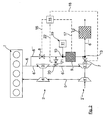
- FIG. 1 schematically is a first embodiment of a process control according to the invention and a device according to the invention for the purification of an exhaust gas flow one by means of an exhaust gas turbocharger 2 in one stage charged internal combustion engine 1 shown.
- the exhaust gas turbocharger 2 has an exhaust gas turbine 3 and a compressor 4. By means of the compressor 4, the charge air 5 is charged, the compressor 4 being driven by means of the exhaust gas turbine 3.
- an exhaust gas stream 6 coming from the internal combustion engine 1 branches off into a main exhaust gas stream 6 'and an exhaust gas sub-stream 6 "downstream of the exhaust gas turbine 3 is a variable throttle device 7 formed in the exhaust gas stream 6', for example by an engine stall or engine brake flap.
- a further variable throttling device 8 is arranged in the partial exhaust gas stream 6 "as seen in the flow direction. Downstream of this variable throttle device 8, a reactor 9 is arranged in the partial exhaust stream 6 "upstream of the reactor 9.
- a metering point 10 for an ammonia precursor substance is provided as reductant 11 to be decomposed downstream of the reactor, the partial exhaust stream 6" flows downstream of the variable throttle device 7 back into the main -Abgasstrom 6 ', so that these two exhaust gas streams then together as ammonia-containing exhaust gas stream 6 "', as will be described in more detail below, an SCR catalyst 12 is supplied.
- the reactor 9 may optionally heat energy from the outside are supplied, for example by means of an electric heater.
- a further SCR catalyst 14 may be arranged downstream of the reactor 9 and upstream of a point of injection 13 of the exhaust gas partial stream 6 "in the exhaust gas stream 6 '.
- a control and / or regulating device 15 is shown, the signal lines shown here by dashed lines 16, 17 and 18th signal technology with the two throttle devices 7, 8 or with a reduction means 11 having metering device 19 is coupled.
- the basic mode of operation of this variant of the invention is such that, under defined operating conditions, by controlling the variable throttle device 7 and / or the variable throttle device 8, a defined amount of exhaust gas can be diverted from the exhaust gas stream 6 as partial exhaust stream 6 "and fed to the reactor 9.
- This partial exhaust gas stream 6" becomes upstream of the reactor 9, by means of the control and / or regulating device 15, correspondingly defined operating parameters of the internal combustion engine and / or defined reaction parameters of the reactor 9 with a defined amount of a reducing agent 11 to be decomposed applied in the reactor 9 together with the hot exhaust gas of hot exhaust gas partial stream 6 "generates ammonia, which is then fed by means of the partial exhaust gas stream 6" at the Einmündstelle 13 the exhaust stream 6 ', so that it flows as ammonia-containing exhaust stream 6' "to the SCR catalyst 12.
- variable throttle device 7 is controlled by means of the control and / or regulating device 15 and this shut off or throttled to a defined extent, in such a way that the exhaust gas amount or mass diverted as partial exhaust stream 6 "is increased .
- control and / or regulating device 15 and the variable throttle device 8 is driven so that this dammed up as the partial exhaust stream 6 "exhaust amount so that it leads to a significant increase in temperature of the exhaust gas as partial stream 6" 9 to the reactor exhaust gas, in a row a lowered air-fuel ratio and / or increased Ausschiebearbeit the internal combustion engine comes.
- the method described above is only one way of conducting the process, but clearly shows the advantage of the solution according to the invention, by means of the damming and / or deflection of an exhaust gas flow can be ensured in a simple manner that for the release of ammonia, especially in idle and / or low load operation of On the other hand, the amount of exhaust gas and thus the amount of heat that is supplied to the reactor 9 for decomposition of the reducing agent, can be significantly increased.
- FIG. 2 an alternative embodiment is shown in which, unlike the embodiment of Fig. 1 a two-stage supercharging by means of an additional exhaust gas turbocharger 2 'takes place, which has an exhaust gas turbine 3' and a compressor 4 '.
- the front exhaust gas turbine 3 seen in the flow direction is preferably designed as a high-pressure turbine, while the downstream exhaust gas turbine 3 'is designed as a low-pressure turbine.
- a further variable throttle device 21 is arranged, which is connected via a signal line 22 to the control and / or regulating device 15 is.
- Fig. 3 is shown a further alternative embodiment, in which again in turn a two-stage supercharging of the internal combustion engine in the sense of Fig. 2 he follows.
- variable throttle device 25 When controlling the variable throttle device 25 by means of the control and / or regulating device 15, a bypass to the exhaust gas turbine 3 can be opened via the waste gate line 23.
- the variable throttle device 8 can then be controlled by the control and / or regulating device 15 such that an exhaust gas partial flow 6 "is fed to the reactor 9, where ammonia production then takes place in the manner described above Functioning of those as they have already been explained in more detail in connection with the embodiments 1 and 2.
- the invention has been described above mainly on the basis of defined idling and / or low-load operating states of the internal combustion engine, in which the provision of desired or necessary reaction conditions in the reactor is jeopardized, for example due to falling below defined temperature and / or exhaust gas threshold values. It goes without saying that all other internal combustion engine operating states, in which the provision of desired or necessary reaction conditions in the reactor is at risk, are expressly included in the scope of protection.
Landscapes
- Engineering & Computer Science (AREA)
- Chemical & Material Sciences (AREA)
- Combustion & Propulsion (AREA)
- Mechanical Engineering (AREA)
- General Engineering & Computer Science (AREA)
- Chemical Kinetics & Catalysis (AREA)
- Health & Medical Sciences (AREA)
- Toxicology (AREA)
- Exhaust Gas After Treatment (AREA)
- Exhaust Gas Treatment By Means Of Catalyst (AREA)
Applications Claiming Priority (1)
| Application Number | Priority Date | Filing Date | Title |
|---|---|---|---|
| DE102009035693A DE102009035693A1 (de) | 2009-07-30 | 2009-07-30 | Verfahren und Vorrichtung zur Reinigung eines Abgasstroms einer Brennkraftmaschine |
Publications (3)
| Publication Number | Publication Date |
|---|---|
| EP2280154A2 true EP2280154A2 (fr) | 2011-02-02 |
| EP2280154A3 EP2280154A3 (fr) | 2013-02-13 |
| EP2280154B1 EP2280154B1 (fr) | 2015-08-05 |
Family
ID=43032955
Family Applications (1)
| Application Number | Title | Priority Date | Filing Date |
|---|---|---|---|
| EP10005786.8A Active EP2280154B1 (fr) | 2009-07-30 | 2010-06-04 | Procédé et dispositif de nettoyage des gaz d'échappement d'un moteur à combustion interne |
Country Status (3)
| Country | Link |
|---|---|
| EP (1) | EP2280154B1 (fr) |
| CN (1) | CN101988411B (fr) |
| DE (1) | DE102009035693A1 (fr) |
Cited By (4)
| Publication number | Priority date | Publication date | Assignee | Title |
|---|---|---|---|---|
| CN103380051A (zh) * | 2011-02-24 | 2013-10-30 | 三菱重工业株式会社 | 船体阻力减少装置 |
| CN106368801A (zh) * | 2015-07-24 | 2017-02-01 | 苏州金威特工具有限公司 | 一种动力随油门操控装置放松立即减弱的割草机的工作方法 |
| CN106368802A (zh) * | 2015-07-24 | 2017-02-01 | 苏州金威特工具有限公司 | 动力随油门操控装置的放松立即减弱的割草机 |
| CN106368797A (zh) * | 2015-07-24 | 2017-02-01 | 苏州金威特工具有限公司 | 具有废气涡轮增压辅助装置的割草机 |
Families Citing this family (3)
| Publication number | Priority date | Publication date | Assignee | Title |
|---|---|---|---|---|
| DK177791B1 (en) * | 2013-05-21 | 2014-07-07 | Man Diesel & Turbo Deutschland | Large Turbocharged Slow Running Two-Stroke Diesel Engine and Method for Obtaining Characteristics of a Butterfly Valve in a large Two-Stroke Diesel Engine |
| KR101708099B1 (ko) * | 2014-12-31 | 2017-02-17 | 두산엔진주식회사 | 선택적 촉매 환원 시스템 및 이를 포함한 동력 장치 |
| DE102017203878A1 (de) * | 2017-03-09 | 2018-09-13 | Robert Bosch Gmbh | Verfahren zum Spülen eines zur Einspritzung einer Flüssigkeit in einen Abgasstrom eines Verbrennungsmotors eines Straßenkraftfahrzeugs dienenden Dosiermoduls |
Citations (5)
| Publication number | Priority date | Publication date | Assignee | Title |
|---|---|---|---|---|
| EP0487886B1 (fr) | 1990-11-29 | 1994-04-13 | MAN Nutzfahrzeuge Aktiengesellschaft | Procédé et installation pour la réduction catalytique sélective de NOx des gaz d'échappement contenant de l'oxygène |
| EP0555746B1 (fr) | 1992-02-10 | 1997-09-10 | MAN Nutzfahrzeuge Aktiengesellschaft | Dispositif pour la réduction catalytique de NOx |
| DE10206028A1 (de) | 2002-02-14 | 2003-08-28 | Man Nutzfahrzeuge Ag | Verfahren und Vorrichtung zur Erzeugung von Ammoniak |
| EP1052009B1 (fr) | 1999-03-25 | 2005-04-20 | Man Nutzfahrzeuge Ag | Procédé pour traiter les gaz d'échappement d'un moteur à combustion interne en utilisant de l'urée |
| DE102007061005A1 (de) | 2007-12-18 | 2009-06-25 | Man Nutzfahrzeuge Ag | Verfahren zur Verbesserung der Hydrolyse eines Reduktionsmittels in einem Abgasnachbehandlungssystem |
Family Cites Families (6)
| Publication number | Priority date | Publication date | Assignee | Title |
|---|---|---|---|---|
| DE4310926A1 (de) * | 1993-04-02 | 1994-10-06 | Siemens Ag | Vorrichtung und Verfahren zur Schadstoffminderung im Abgas |
| DE19740702C1 (de) * | 1997-09-16 | 1998-11-19 | Siemens Ag | Verfahren und Vorrichtung zum Betrieb einer mit Luftüberschuß arbeitenden Brennkraftmaschine |
| JP2002188432A (ja) * | 2000-12-19 | 2002-07-05 | Isuzu Motors Ltd | ディーゼルエンジンの排気浄化装置 |
| DE10218255B4 (de) * | 2002-04-24 | 2005-07-07 | J. Eberspächer GmbH & Co. KG | Abgasanlage für einen Dieselmotor und zugehöriger Schalldämpfer |
| US7363761B1 (en) * | 2006-10-31 | 2008-04-29 | International Engine Intellectual Property Company, Llc | Exhaust gas throttle for divided turbine housing turbocharger |
| DE102007033424A1 (de) * | 2007-07-18 | 2009-01-22 | Man Nutzfahrzeuge Ag | Selbstreinigendes Abgasnachbehandlungssystem |
-
2009
- 2009-07-30 DE DE102009035693A patent/DE102009035693A1/de not_active Withdrawn
-
2010
- 2010-06-04 EP EP10005786.8A patent/EP2280154B1/fr active Active
- 2010-07-30 CN CN201010248754.0A patent/CN101988411B/zh active Active
Patent Citations (5)
| Publication number | Priority date | Publication date | Assignee | Title |
|---|---|---|---|---|
| EP0487886B1 (fr) | 1990-11-29 | 1994-04-13 | MAN Nutzfahrzeuge Aktiengesellschaft | Procédé et installation pour la réduction catalytique sélective de NOx des gaz d'échappement contenant de l'oxygène |
| EP0555746B1 (fr) | 1992-02-10 | 1997-09-10 | MAN Nutzfahrzeuge Aktiengesellschaft | Dispositif pour la réduction catalytique de NOx |
| EP1052009B1 (fr) | 1999-03-25 | 2005-04-20 | Man Nutzfahrzeuge Ag | Procédé pour traiter les gaz d'échappement d'un moteur à combustion interne en utilisant de l'urée |
| DE10206028A1 (de) | 2002-02-14 | 2003-08-28 | Man Nutzfahrzeuge Ag | Verfahren und Vorrichtung zur Erzeugung von Ammoniak |
| DE102007061005A1 (de) | 2007-12-18 | 2009-06-25 | Man Nutzfahrzeuge Ag | Verfahren zur Verbesserung der Hydrolyse eines Reduktionsmittels in einem Abgasnachbehandlungssystem |
Cited By (4)
| Publication number | Priority date | Publication date | Assignee | Title |
|---|---|---|---|---|
| CN103380051A (zh) * | 2011-02-24 | 2013-10-30 | 三菱重工业株式会社 | 船体阻力减少装置 |
| CN106368801A (zh) * | 2015-07-24 | 2017-02-01 | 苏州金威特工具有限公司 | 一种动力随油门操控装置放松立即减弱的割草机的工作方法 |
| CN106368802A (zh) * | 2015-07-24 | 2017-02-01 | 苏州金威特工具有限公司 | 动力随油门操控装置的放松立即减弱的割草机 |
| CN106368797A (zh) * | 2015-07-24 | 2017-02-01 | 苏州金威特工具有限公司 | 具有废气涡轮增压辅助装置的割草机 |
Also Published As
| Publication number | Publication date |
|---|---|
| CN101988411B (zh) | 2015-04-01 |
| CN101988411A (zh) | 2011-03-23 |
| DE102009035693A1 (de) | 2011-02-10 |
| EP2280154B1 (fr) | 2015-08-05 |
| EP2280154A3 (fr) | 2013-02-13 |
Similar Documents
| Publication | Publication Date | Title |
|---|---|---|
| EP2280155B1 (fr) | Procédé et dispositif de nettoyage d'un flux de gaz d'échappement d'un moteur à combustion interne | |
| EP2280154B1 (fr) | Procédé et dispositif de nettoyage des gaz d'échappement d'un moteur à combustion interne | |
| EP1338562B1 (fr) | Procédé et dispositif pour la production d'ammoniac | |
| EP3660287B1 (fr) | Système de post-traitement des gaz d'échappement ainsi que procédé de post-traitement des gaz d'échappement d'un moteur à combustion interne | |
| EP2075050B1 (fr) | Procédé et dispositif d'amélioration de l'hydrolyse d'un moyen de réduction dans un système de retraitement des gaz d'échappement | |
| EP1892394B1 (fr) | Système de traitement postérieur de gaz d'échappement | |
| EP2635790B1 (fr) | Moteur à combustion interne de véhicule automobile équipé d'une recirculation de gaz d'échappement | |
| EP2206898B1 (fr) | Procédé de post-traitement d'un flux de gaz d'un moteur à combustion multi-cylindrique d'un véhicule ainsi qu'installation de post-traitement des gaz d'échappement | |
| DE102008017280B4 (de) | Anordnung zur Beeinflussung des Umsatzverhaltens von Abgaskatalysatoren | |
| EP1900916A2 (fr) | Système de traitement postérieur de gaz d'échappement | |
| DE102014201579A1 (de) | Brennkraftmaschine mit selektivem Katalysator zur Reduzierung der Stickoxide und Verfahren zum Betreiben einer derartigen Brennkraftmaschine | |
| EP1892395A1 (fr) | Système de traitement de gaz d'échappement | |
| DE102008043487A1 (de) | Brennkraftmaschine mit Turbolader und Oxidationskatalysator | |
| EP3486444B1 (fr) | Procédé de traitement de gaz d'échappement d'un moteur à combustion interne | |
| EP2376749A1 (fr) | Procédé de fonctionnement de composants pour le post-traitement des gaz d'échappement et dispositif de post-traitement des gaz d'échappement | |
| EP2811130B1 (fr) | Procédé et dispositif de désulfuration de reflux de gaz d'échappement | |
| DE102019131829B3 (de) | Verfahren zur Abgasnachbehandlung eines Verbrennungsmotors | |
| DE102013208743B4 (de) | Vorrichtung zur Abgasnachbehandlung | |
| DE102015004063A1 (de) | Anordnung und Verfahren | |
| DE102021103234A1 (de) | Verfahren zur Abgasnachbehandlung eines Verbrennungsmotors sowie Abgasnachbehandlungssystem | |
| EP3751106A1 (fr) | Système et méthode de purification des gaz d'échappement | |
| DE102019105748A1 (de) | Verfahren zur Abgasnachbehandlung eines Verbrennungsmotors sowie Abgasnachbehandlungssystem | |
| DE102019107544A1 (de) | Verfahren zum Betreiben eines Abgasnachbehandlungssystems sowie Abgasnachbehandlungssystem | |
| EP4074946B1 (fr) | Procédé de post-traitement des gaz d'échappement d'un moteur diesel et moteur diesel | |
| EP4361413A1 (fr) | Procédé de fonctionnement d'un système de post-traitement des gaz d'échappement et système de post-traitement des gaz d'échappement |
Legal Events
| Date | Code | Title | Description |
|---|---|---|---|
| PUAI | Public reference made under article 153(3) epc to a published international application that has entered the european phase |
Free format text: ORIGINAL CODE: 0009012 |
|
| AK | Designated contracting states |
Kind code of ref document: A2 Designated state(s): AL AT BE BG CH CY CZ DE DK EE ES FI FR GB GR HR HU IE IS IT LI LT LU LV MC MK MT NL NO PL PT RO SE SI SK SM TR |
|
| AX | Request for extension of the european patent |
Extension state: BA ME RS |
|
| RAP1 | Party data changed (applicant data changed or rights of an application transferred) |
Owner name: MAM TRUCK & BUS AG |
|
| PUAL | Search report despatched |
Free format text: ORIGINAL CODE: 0009013 |
|
| AK | Designated contracting states |
Kind code of ref document: A3 Designated state(s): AL AT BE BG CH CY CZ DE DK EE ES FI FR GB GR HR HU IE IS IT LI LT LU LV MC MK MT NL NO PL PT RO SE SI SK SM TR |
|
| AX | Request for extension of the european patent |
Extension state: BA ME RS |
|
| RIC1 | Information provided on ipc code assigned before grant |
Ipc: F02D 9/06 20060101ALI20130109BHEP Ipc: F02B 37/18 20060101ALI20130109BHEP Ipc: F01N 3/20 20060101AFI20130109BHEP Ipc: F02B 37/00 20060101ALI20130109BHEP Ipc: F02B 37/013 20060101ALI20130109BHEP |
|
| 17P | Request for examination filed |
Effective date: 20130716 |
|
| RBV | Designated contracting states (corrected) |
Designated state(s): AL AT BE BG CH CY CZ DE DK EE ES FI FR GB GR HR HU IE IS IT LI LT LU LV MC MK MT NL NO PL PT RO SE SI SK SM TR |
|
| RIN1 | Information on inventor provided before grant (corrected) |
Inventor name: DOERING, ANDREAS |
|
| GRAP | Despatch of communication of intention to grant a patent |
Free format text: ORIGINAL CODE: EPIDOSNIGR1 |
|
| RIC1 | Information provided on ipc code assigned before grant |
Ipc: F02D 9/06 20060101ALI20140922BHEP Ipc: F02B 37/18 20060101ALI20140922BHEP Ipc: F02D 41/00 20060101ALI20140922BHEP Ipc: F02B 37/00 20060101ALI20140922BHEP Ipc: F01N 3/20 20060101AFI20140922BHEP Ipc: F02B 37/013 20060101ALI20140922BHEP |
|
| INTG | Intention to grant announced |
Effective date: 20141016 |
|
| INTG | Intention to grant announced |
Effective date: 20141021 |
|
| GRAP | Despatch of communication of intention to grant a patent |
Free format text: ORIGINAL CODE: EPIDOSNIGR1 |
|
| INTG | Intention to grant announced |
Effective date: 20150220 |
|
| GRAS | Grant fee paid |
Free format text: ORIGINAL CODE: EPIDOSNIGR3 |
|
| GRAA | (expected) grant |
Free format text: ORIGINAL CODE: 0009210 |
|
| AK | Designated contracting states |
Kind code of ref document: B1 Designated state(s): AL AT BE BG CH CY CZ DE DK EE ES FI FR GB GR HR HU IE IS IT LI LT LU LV MC MK MT NL NO PL PT RO SE SI SK SM TR |
|
| REG | Reference to a national code |
Ref country code: GB Ref legal event code: FG4D Free format text: NOT ENGLISH |
|
| REG | Reference to a national code |
Ref country code: CH Ref legal event code: EP |
|
| REG | Reference to a national code |
Ref country code: AT Ref legal event code: REF Ref document number: 740844 Country of ref document: AT Kind code of ref document: T Effective date: 20150815 |
|
| REG | Reference to a national code |
Ref country code: IE Ref legal event code: FG4D Free format text: LANGUAGE OF EP DOCUMENT: GERMAN |
|
| REG | Reference to a national code |
Ref country code: DE Ref legal event code: R096 Ref document number: 502010009978 Country of ref document: DE |
|
| REG | Reference to a national code |
Ref country code: SE Ref legal event code: TRGR |
|
| REG | Reference to a national code |
Ref country code: NL Ref legal event code: FP |
|
| REG | Reference to a national code |
Ref country code: LT Ref legal event code: MG4D |
|
| PG25 | Lapsed in a contracting state [announced via postgrant information from national office to epo] |
Ref country code: LT Free format text: LAPSE BECAUSE OF FAILURE TO SUBMIT A TRANSLATION OF THE DESCRIPTION OR TO PAY THE FEE WITHIN THE PRESCRIBED TIME-LIMIT Effective date: 20150805 Ref country code: FI Free format text: LAPSE BECAUSE OF FAILURE TO SUBMIT A TRANSLATION OF THE DESCRIPTION OR TO PAY THE FEE WITHIN THE PRESCRIBED TIME-LIMIT Effective date: 20150805 Ref country code: NO Free format text: LAPSE BECAUSE OF FAILURE TO SUBMIT A TRANSLATION OF THE DESCRIPTION OR TO PAY THE FEE WITHIN THE PRESCRIBED TIME-LIMIT Effective date: 20151105 Ref country code: LV Free format text: LAPSE BECAUSE OF FAILURE TO SUBMIT A TRANSLATION OF THE DESCRIPTION OR TO PAY THE FEE WITHIN THE PRESCRIBED TIME-LIMIT Effective date: 20150805 Ref country code: GR Free format text: LAPSE BECAUSE OF FAILURE TO SUBMIT A TRANSLATION OF THE DESCRIPTION OR TO PAY THE FEE WITHIN THE PRESCRIBED TIME-LIMIT Effective date: 20151106 |
|
| PG25 | Lapsed in a contracting state [announced via postgrant information from national office to epo] |
Ref country code: HR Free format text: LAPSE BECAUSE OF FAILURE TO SUBMIT A TRANSLATION OF THE DESCRIPTION OR TO PAY THE FEE WITHIN THE PRESCRIBED TIME-LIMIT Effective date: 20150805 Ref country code: PT Free format text: LAPSE BECAUSE OF FAILURE TO SUBMIT A TRANSLATION OF THE DESCRIPTION OR TO PAY THE FEE WITHIN THE PRESCRIBED TIME-LIMIT Effective date: 20151207 Ref country code: IS Free format text: LAPSE BECAUSE OF FAILURE TO SUBMIT A TRANSLATION OF THE DESCRIPTION OR TO PAY THE FEE WITHIN THE PRESCRIBED TIME-LIMIT Effective date: 20151205 Ref country code: PL Free format text: LAPSE BECAUSE OF FAILURE TO SUBMIT A TRANSLATION OF THE DESCRIPTION OR TO PAY THE FEE WITHIN THE PRESCRIBED TIME-LIMIT Effective date: 20150805 Ref country code: ES Free format text: LAPSE BECAUSE OF FAILURE TO SUBMIT A TRANSLATION OF THE DESCRIPTION OR TO PAY THE FEE WITHIN THE PRESCRIBED TIME-LIMIT Effective date: 20150805 |
|
| PG25 | Lapsed in a contracting state [announced via postgrant information from national office to epo] |
Ref country code: DK Free format text: LAPSE BECAUSE OF FAILURE TO SUBMIT A TRANSLATION OF THE DESCRIPTION OR TO PAY THE FEE WITHIN THE PRESCRIBED TIME-LIMIT Effective date: 20150805 Ref country code: SK Free format text: LAPSE BECAUSE OF FAILURE TO SUBMIT A TRANSLATION OF THE DESCRIPTION OR TO PAY THE FEE WITHIN THE PRESCRIBED TIME-LIMIT Effective date: 20150805 Ref country code: EE Free format text: LAPSE BECAUSE OF FAILURE TO SUBMIT A TRANSLATION OF THE DESCRIPTION OR TO PAY THE FEE WITHIN THE PRESCRIBED TIME-LIMIT Effective date: 20150805 Ref country code: CZ Free format text: LAPSE BECAUSE OF FAILURE TO SUBMIT A TRANSLATION OF THE DESCRIPTION OR TO PAY THE FEE WITHIN THE PRESCRIBED TIME-LIMIT Effective date: 20150805 |
|
| REG | Reference to a national code |
Ref country code: DE Ref legal event code: R097 Ref document number: 502010009978 Country of ref document: DE |
|
| PG25 | Lapsed in a contracting state [announced via postgrant information from national office to epo] |
Ref country code: RO Free format text: LAPSE BECAUSE OF FAILURE TO SUBMIT A TRANSLATION OF THE DESCRIPTION OR TO PAY THE FEE WITHIN THE PRESCRIBED TIME-LIMIT Effective date: 20150805 |
|
| PLBE | No opposition filed within time limit |
Free format text: ORIGINAL CODE: 0009261 |
|
| STAA | Information on the status of an ep patent application or granted ep patent |
Free format text: STATUS: NO OPPOSITION FILED WITHIN TIME LIMIT |
|
| REG | Reference to a national code |
Ref country code: FR Ref legal event code: PLFP Year of fee payment: 7 |
|
| 26N | No opposition filed |
Effective date: 20160509 |
|
| PG25 | Lapsed in a contracting state [announced via postgrant information from national office to epo] |
Ref country code: SI Free format text: LAPSE BECAUSE OF FAILURE TO SUBMIT A TRANSLATION OF THE DESCRIPTION OR TO PAY THE FEE WITHIN THE PRESCRIBED TIME-LIMIT Effective date: 20150805 |
|
| PG25 | Lapsed in a contracting state [announced via postgrant information from national office to epo] |
Ref country code: BE Free format text: LAPSE BECAUSE OF NON-PAYMENT OF DUE FEES Effective date: 20160630 |
|
| PG25 | Lapsed in a contracting state [announced via postgrant information from national office to epo] |
Ref country code: MC Free format text: LAPSE BECAUSE OF FAILURE TO SUBMIT A TRANSLATION OF THE DESCRIPTION OR TO PAY THE FEE WITHIN THE PRESCRIBED TIME-LIMIT Effective date: 20150805 |
|
| REG | Reference to a national code |
Ref country code: CH Ref legal event code: PL |
|
| GBPC | Gb: european patent ceased through non-payment of renewal fee |
Effective date: 20160604 |
|
| REG | Reference to a national code |
Ref country code: IE Ref legal event code: MM4A |
|
| PG25 | Lapsed in a contracting state [announced via postgrant information from national office to epo] |
Ref country code: CH Free format text: LAPSE BECAUSE OF NON-PAYMENT OF DUE FEES Effective date: 20160630 Ref country code: LI Free format text: LAPSE BECAUSE OF NON-PAYMENT OF DUE FEES Effective date: 20160630 |
|
| PG25 | Lapsed in a contracting state [announced via postgrant information from national office to epo] |
Ref country code: IE Free format text: LAPSE BECAUSE OF NON-PAYMENT OF DUE FEES Effective date: 20160604 Ref country code: GB Free format text: LAPSE BECAUSE OF NON-PAYMENT OF DUE FEES Effective date: 20160604 |
|
| REG | Reference to a national code |
Ref country code: FR Ref legal event code: PLFP Year of fee payment: 8 |
|
| REG | Reference to a national code |
Ref country code: AT Ref legal event code: MM01 Ref document number: 740844 Country of ref document: AT Kind code of ref document: T Effective date: 20160604 |
|
| PG25 | Lapsed in a contracting state [announced via postgrant information from national office to epo] |
Ref country code: AT Free format text: LAPSE BECAUSE OF NON-PAYMENT OF DUE FEES Effective date: 20160604 |
|
| PG25 | Lapsed in a contracting state [announced via postgrant information from national office to epo] |
Ref country code: CY Free format text: LAPSE BECAUSE OF FAILURE TO SUBMIT A TRANSLATION OF THE DESCRIPTION OR TO PAY THE FEE WITHIN THE PRESCRIBED TIME-LIMIT Effective date: 20150805 Ref country code: HU Free format text: LAPSE BECAUSE OF FAILURE TO SUBMIT A TRANSLATION OF THE DESCRIPTION OR TO PAY THE FEE WITHIN THE PRESCRIBED TIME-LIMIT; INVALID AB INITIO Effective date: 20100604 Ref country code: SM Free format text: LAPSE BECAUSE OF FAILURE TO SUBMIT A TRANSLATION OF THE DESCRIPTION OR TO PAY THE FEE WITHIN THE PRESCRIBED TIME-LIMIT Effective date: 20150805 |
|
| PG25 | Lapsed in a contracting state [announced via postgrant information from national office to epo] |
Ref country code: LU Free format text: LAPSE BECAUSE OF NON-PAYMENT OF DUE FEES Effective date: 20160604 Ref country code: MT Free format text: LAPSE BECAUSE OF FAILURE TO SUBMIT A TRANSLATION OF THE DESCRIPTION OR TO PAY THE FEE WITHIN THE PRESCRIBED TIME-LIMIT Effective date: 20150805 Ref country code: TR Free format text: LAPSE BECAUSE OF FAILURE TO SUBMIT A TRANSLATION OF THE DESCRIPTION OR TO PAY THE FEE WITHIN THE PRESCRIBED TIME-LIMIT Effective date: 20150805 Ref country code: MK Free format text: LAPSE BECAUSE OF FAILURE TO SUBMIT A TRANSLATION OF THE DESCRIPTION OR TO PAY THE FEE WITHIN THE PRESCRIBED TIME-LIMIT Effective date: 20150805 |
|
| REG | Reference to a national code |
Ref country code: FR Ref legal event code: PLFP Year of fee payment: 9 |
|
| PG25 | Lapsed in a contracting state [announced via postgrant information from national office to epo] |
Ref country code: BG Free format text: LAPSE BECAUSE OF FAILURE TO SUBMIT A TRANSLATION OF THE DESCRIPTION OR TO PAY THE FEE WITHIN THE PRESCRIBED TIME-LIMIT Effective date: 20150805 |
|
| PG25 | Lapsed in a contracting state [announced via postgrant information from national office to epo] |
Ref country code: AL Free format text: LAPSE BECAUSE OF FAILURE TO SUBMIT A TRANSLATION OF THE DESCRIPTION OR TO PAY THE FEE WITHIN THE PRESCRIBED TIME-LIMIT Effective date: 20150805 |
|
| REG | Reference to a national code |
Ref country code: DE Ref legal event code: R082 Ref document number: 502010009978 Country of ref document: DE Representative=s name: NEUBAUER LIEBL BIERSCHNEIDER, DE Ref country code: DE Ref legal event code: R081 Ref document number: 502010009978 Country of ref document: DE Owner name: MAN TRUCK & BUS SE, DE Free format text: FORMER OWNER: MAN TRUCK & BUS AG, 80995 MUENCHEN, DE Ref country code: DE Ref legal event code: R082 Ref document number: 502010009978 Country of ref document: DE Representative=s name: NEUBAUER LIEBL BIERSCHNEIDER MASSINGER, DE |
|
| PGFP | Annual fee paid to national office [announced via postgrant information from national office to epo] |
Ref country code: IT Payment date: 20230620 Year of fee payment: 14 |
|
| PGFP | Annual fee paid to national office [announced via postgrant information from national office to epo] |
Ref country code: DE Payment date: 20240627 Year of fee payment: 15 |
|
| PGFP | Annual fee paid to national office [announced via postgrant information from national office to epo] |
Ref country code: NL Payment date: 20240625 Year of fee payment: 15 |
|
| PGFP | Annual fee paid to national office [announced via postgrant information from national office to epo] |
Ref country code: FR Payment date: 20240625 Year of fee payment: 15 |
|
| PGFP | Annual fee paid to national office [announced via postgrant information from national office to epo] |
Ref country code: SE Payment date: 20240624 Year of fee payment: 15 |