EP2280150A1 - Gas turbine engine with integrated starter-generator and corresponding operating method - Google Patents
Gas turbine engine with integrated starter-generator and corresponding operating method Download PDFInfo
- Publication number
- EP2280150A1 EP2280150A1 EP10170964A EP10170964A EP2280150A1 EP 2280150 A1 EP2280150 A1 EP 2280150A1 EP 10170964 A EP10170964 A EP 10170964A EP 10170964 A EP10170964 A EP 10170964A EP 2280150 A1 EP2280150 A1 EP 2280150A1
- Authority
- EP
- European Patent Office
- Prior art keywords
- gas turbine
- turbine engine
- conductive coils
- module
- power
- Prior art date
- Legal status (The legal status is an assumption and is not a legal conclusion. Google has not performed a legal analysis and makes no representation as to the accuracy of the status listed.)
- Granted
Links
Images




Classifications
-
- F—MECHANICAL ENGINEERING; LIGHTING; HEATING; WEAPONS; BLASTING
- F01—MACHINES OR ENGINES IN GENERAL; ENGINE PLANTS IN GENERAL; STEAM ENGINES
- F01D—NON-POSITIVE DISPLACEMENT MACHINES OR ENGINES, e.g. STEAM TURBINES
- F01D9/00—Stators
- F01D9/06—Fluid supply conduits to nozzles or the like
- F01D9/065—Fluid supply or removal conduits traversing the working fluid flow, e.g. for lubrication-, cooling-, or sealing fluids
-
- F—MECHANICAL ENGINEERING; LIGHTING; HEATING; WEAPONS; BLASTING
- F01—MACHINES OR ENGINES IN GENERAL; ENGINE PLANTS IN GENERAL; STEAM ENGINES
- F01D—NON-POSITIVE DISPLACEMENT MACHINES OR ENGINES, e.g. STEAM TURBINES
- F01D15/00—Adaptations of machines or engines for special use; Combinations of engines with devices driven thereby
- F01D15/10—Adaptations for driving, or combinations with, electric generators
-
- F—MECHANICAL ENGINEERING; LIGHTING; HEATING; WEAPONS; BLASTING
- F02—COMBUSTION ENGINES; HOT-GAS OR COMBUSTION-PRODUCT ENGINE PLANTS
- F02C—GAS-TURBINE PLANTS; AIR INTAKES FOR JET-PROPULSION PLANTS; CONTROLLING FUEL SUPPLY IN AIR-BREATHING JET-PROPULSION PLANTS
- F02C7/00—Features, components parts, details or accessories, not provided for in, or of interest apart form groups F02C1/00 - F02C6/00; Air intakes for jet-propulsion plants
- F02C7/26—Starting; Ignition
- F02C7/268—Starting drives for the rotor, acting directly on the rotor of the gas turbine to be started
- F02C7/275—Mechanical drives
-
- F—MECHANICAL ENGINEERING; LIGHTING; HEATING; WEAPONS; BLASTING
- F02—COMBUSTION ENGINES; HOT-GAS OR COMBUSTION-PRODUCT ENGINE PLANTS
- F02C—GAS-TURBINE PLANTS; AIR INTAKES FOR JET-PROPULSION PLANTS; CONTROLLING FUEL SUPPLY IN AIR-BREATHING JET-PROPULSION PLANTS
- F02C7/00—Features, components parts, details or accessories, not provided for in, or of interest apart form groups F02C1/00 - F02C6/00; Air intakes for jet-propulsion plants
- F02C7/32—Arrangement, mounting, or driving, of auxiliaries
-
- F—MECHANICAL ENGINEERING; LIGHTING; HEATING; WEAPONS; BLASTING
- F04—POSITIVE - DISPLACEMENT MACHINES FOR LIQUIDS; PUMPS FOR LIQUIDS OR ELASTIC FLUIDS
- F04D—NON-POSITIVE-DISPLACEMENT PUMPS
- F04D25/00—Pumping installations or systems
- F04D25/02—Units comprising pumps and their driving means
- F04D25/04—Units comprising pumps and their driving means the pump being fluid-driven
-
- F—MECHANICAL ENGINEERING; LIGHTING; HEATING; WEAPONS; BLASTING
- F04—POSITIVE - DISPLACEMENT MACHINES FOR LIQUIDS; PUMPS FOR LIQUIDS OR ELASTIC FLUIDS
- F04D—NON-POSITIVE-DISPLACEMENT PUMPS
- F04D25/00—Pumping installations or systems
- F04D25/02—Units comprising pumps and their driving means
- F04D25/06—Units comprising pumps and their driving means the pump being electrically driven
- F04D25/0606—Units comprising pumps and their driving means the pump being electrically driven the electric motor being specially adapted for integration in the pump
-
- F—MECHANICAL ENGINEERING; LIGHTING; HEATING; WEAPONS; BLASTING
- F16—ENGINEERING ELEMENTS AND UNITS; GENERAL MEASURES FOR PRODUCING AND MAINTAINING EFFECTIVE FUNCTIONING OF MACHINES OR INSTALLATIONS; THERMAL INSULATION IN GENERAL
- F16L—PIPES; JOINTS OR FITTINGS FOR PIPES; SUPPORTS FOR PIPES, CABLES OR PROTECTIVE TUBING; MEANS FOR THERMAL INSULATION IN GENERAL
- F16L9/00—Rigid pipes
- F16L9/003—Rigid pipes with a rectangular cross-section
-
- Y—GENERAL TAGGING OF NEW TECHNOLOGICAL DEVELOPMENTS; GENERAL TAGGING OF CROSS-SECTIONAL TECHNOLOGIES SPANNING OVER SEVERAL SECTIONS OF THE IPC; TECHNICAL SUBJECTS COVERED BY FORMER USPC CROSS-REFERENCE ART COLLECTIONS [XRACs] AND DIGESTS
- Y02—TECHNOLOGIES OR APPLICATIONS FOR MITIGATION OR ADAPTATION AGAINST CLIMATE CHANGE
- Y02T—CLIMATE CHANGE MITIGATION TECHNOLOGIES RELATED TO TRANSPORTATION
- Y02T50/00—Aeronautics or air transport
- Y02T50/60—Efficient propulsion technologies, e.g. for aircraft
Definitions
- the present invention relates generally to gas turbine engines, and more particularly to a gas turbine engine including an electric starter/ generator integrated into a compressor rotor and casing of the gas turbine engine.
- a typical gas turbine engine 10 includes an engine casing 12 that houses a compressor rotor 14, a combustor 16, a turbine rotor 18, and a shaft 20 connecting the compressor rotor to the turbine rotor.
- the shaft is rotatably mounted to the casing by way of an internal gearbox 22 and bearings 24 disposed between the compressor rotor and the turbine rotor.
- the compressor rotor and the turbine rotor rotate with the shaft.
- the gas turbine engine is mounted within a nacelle 25.
- the gas turbine engine also includes various accessory components that receive mechanical power from an accessory gearbox 26 that is mounted external to the engine casing.
- the accessory gearbox receives mechanical power from the gas turbine engine shaft via a power-takeoff shaftline 28 that extends radially outward from the internal gearbox through the gas turbine engine casing, substantially as disclosed, for example, in U.S. Pat. No. 7,246,495 issued to Muramutsu et al .
- the compressor rotor 14 includes an axially-spaced plurality of compressor discs 30 mounted to the shaft and separated by interstage spacers 32 also mounted to the shaft.
- the compressor rotor discs and the interstage spacers together form the compressor rotor.
- Each compressor disc supports a circumferential array of compressor blades 34, while each interstage spacer supports a series of labyrinth seal teeth.
- the design of the compressor as a whole is driven by working fluid requirements of the gas turbine engine thermodynamic cycle.
- the compressor rotor assembly is optimized for weight reduction, key dimensions of the discs and the blades being manufactured to approximately 0.0001" tolerances in order to have just enough material to support centripetal strains induced when the rotor rotates at operational speeds under operational temperatures.
- the gas turbine engine casing Adjacent to the compressor rotor, the gas turbine engine casing supports a plurality of compressor vane assemblies 36 that are axially interspaced with the circumferential arrays of compressor blades.
- Each compressor vane assembly includes a circumferential array of vanes 37 that extend inward from the casing to a shroud ring 38 that is closely radially adjacent to a corresponding interstage spacer of the compressor rotor.
- each vane is pivotable around a shaft extending radially from the casing to the shroud ring, and each circumferential array of vanes is synchronously movable by a control ring mounted outside the gas turbine engine casing. Vane dimensions are optimized for aerodynamic performance (low flow resistance) and for maximal variability of flow area as the vanes are rotated.
- the turbine portion of the casing is similarly constructed.
- the accessory gearbox 26 houses an accessory geartrain 40 for driving the accessory components.
- the accessory components include, for example, a fuel pump 42, an oil pump 44, and an alternator or generator 46.
- Each accessory component is mounted directly to the accessory gearbox and is driven from a corresponding gear within the accessory geartrain.
- the accessory gearbox also supports an engine starter 48, which can be pneumatic, hydraulic, electrical, or combustion-driven.
- the engine starter is clutch-connected to the accessory geartrain so that the engine starter will not place an unnecessary load on the accessory geartrain during operation of the gas turbine engine 10.
- the engine starter can be integrated into the accessory gearbox, as disclosed, for example, by U.S. Pat. No. 5,555,722 issued to Mehr-Ayin et al.
- the engine starter drives the power-takeoff shaftline 28, via the accessory geartrain, in order to turn the shaft 20 of the gas turbine engine 10.
- the typical accessory gearbox transfers power from the power-takeoff shaftline to the accessory components during operation, and provides power to the power-takeoff shaftline from the engine starter at startup.
- the engine starter can be integrated with the generator to provide a combined starter/ generator.
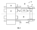
- a typical combined starter/generator 49 includes a stator 50 housing primary windings 54 and exciter field windings 55, and also includes a rotor 60 housing rotor windings 62 and exciter windings 65 that are electrically connected with the primary field windings.
- the rotor is housed within the stator for rotation about an axis of the stator, and the different windings of the starter/ generator can be selectively energized for operation as a starter (motor) or as a generator.
- the exciter field windings 55 are energized to produce a (typically stationary) exciting magnetic field, and tangential motion of the exciter windings 65 across the exciting field induces electrical current in the exciter windings and in the rotor windings 62. In turn, tangential movement of the rotor windings across the primary windings 54 induces electrical currents in the primary windings.
- the primary windings are energized to produce a rotating magnetic field, which electromechanically couples with the rotor windings to cause rotation of the rotor.
- the electromagnetic gaps 67 between the rotor windings and the primary windings, and between the exciter field windings and the exciter windings, are kept as small as possible.
- the rotor windings 62 and the exciter windings 65 are at the circumference of the rotor 60 and are separated from the primary windings 55 by only a narrow ( ⁇ 0.2 inch) air gap to allow for thermal and mechanical strains at operating speed and temperatures.
- the gas turbine engine starting torque determines the sizes and weights of the internal gearbox 22, the power-takeoff shaftline 28, the accessory geartrain 40, and the starter 48.
- the size and placement of the internal gearbox affect the overall axial and radial size of the gas turbine engine and of the gas turbine engine nacelle 25.
- the power-takeoff shaftline and the accessory gearbox 26 introduce structural asymmetries that can adversely impact the aerodynamic performance of the gas turbine engine nacelle.
- mechanical transfer of power to and from the gas turbine engine shaft, via the radial power-takeoff shaftline and the accessory geartrain plays an undesirably important role at many stages of gas turbine engine design.
- common electrical machine winding materials such as aluminum or copper liquefy at 1220F or 1984F, respectively. These materials also exhibit significant thermal strains throughout the operating temperature range of a typical gas turbine engine.
- permanent magnets can be arranged to provide satisfactory electromagnetic coupling with less weight
- typical permanent magnet materials such as neodymium iron boron exhibit structural instability due to thermal fatigue, and also exhibit rapid demagnetization above the materials' respective Curie temperatures. Curie rapid temperatures for typical permanent magnet materials range from 590F up to about 680F, while long-term operating temperatures do not exceed 400F.
- an electric machine can be integrated into fan casing struts and a fan rotor of a gas turbofan engine, as taught by Sharp in U.S. Pat. App. Ser. No. 10/587,346 .
- fan rotors preferably are designed to be as thin and light as possible for enhanced aerodynamic performance, so that the added weight and volume required for generator windings is not desirable in a fan of a gas turbofan engine.
- fan rotor rotational speeds are limited by aerodynamic considerations such as angle-of-attack and drag, while it is desirable for a starter/generator to move at a rotational speed determined by electrical bus requirements.
- a gas turbine engine includes an electrical starter/ generator machine that is integrated into a compressor of the gas turbine engine.
- a gas turbine engine has a casing, a shaft rotatably mounted in the casing, and a compressor rotor and a turbine rotor mounted to the shaft within the casing, with a field magnet mounted in the compressor rotor, and a circumferential array of conductive coils mounted in the casing substantially adjacent to a circle defined by revolution of the field magnet within the casing.
- An electrical system interface module is electrically connected to the circumferential array of conductive coils.
- a compressor blade disc of a gas turbine engine includes a circumferential array of magnets and a compressor vane shroud of the gas turbine engine includes a corresponding circumferential array of conductive coils disposed adjacent to the magnets to form an axial-flux electric starter/generator machine for transfer of power to and from the compressor rotor during starting and operation of the gas turbine engine.
- an interstage spacer of a compressor rotor in a gas turbine engine includes a circumferential array of magnets and a compressor vane shroud of the gas turbine engine includes a corresponding circumferential array of conductive coils disposed adjacent to the magnets to form a radial-flux electric starter/ generator machine for transfer of power to and from the compressor rotor during starting and operation of the gas turbine engine.
- the electrical system interface module includes a starter module for providing electrical current to the conductive coils, a power-takeoff module for receiving current from the conductive coils, and a control module for actuating one of the starter module and the power-takeoff module based on at least a command signal.
- the starter module of the electrical system interface module can be configured to provide three-phase alternating current across the conductive coils for operating the gas turbine engine as a motor. Alternatively, the starter module can be configured to provide pulsed DC current.
- the power-takeoff module of the electrical system interface module can be configured to receive three-phase alternating current from the conductive coils for operating the gas turbine engine as an electrical generator. Alternatively, the power-takeoff module can be configured to receive and commute pulsed DC current.
- a shaft is rotated within a casing of a gas turbine engine by applying a current through an array of conductive coils housed in the casing adjacent to one or more magnets mounted in a compressor rotor fixed to the shaft.
- FIG. 1 is a side sectional view of a gas turbine engine indicating conventional components including an accessory gearbox.
- FIG. 2 is a perspective partial cutaway view of the accessory gearbox shown in FIG. 1 .
- FIG. 3 is a schematic sectional view of a typical starter/generator usable with the gas turbine engine shown in FIG. 1 .
- FIG. 4 is a side sectional view of a portion of a gas turbine engine compressor including an axial-flux starter/generator machine, according to a first embodiment of the present invention.
- FIG. 5 is an axial sectional view of the gas turbine engine shown in FIG. 4 , taken through a plane 5-5 to show conductive coils and power leads in a power-transfer ring of the axial-flux starter/ generator machine.
- FIG. 6 is an axial sectional view of the gas turbine engine shown in FIG. 4 , taken through a plane 6-6 to show permanent magnets in a field ring of the axial-flux starter/ generator machine.
- FIG. 7 is a side sectional view of a portion of a gas turbine engine compressor including a radial-flux starter/generator machine, according to a second embodiment of the present invention.
- FIG. 8 is a schematic illustration of an electrical system interface module for use with either of the starter/ generator machines shown in FIGS. 4-7 , according to an embodiment of the present invention.
- a gas turbine engine 110 has a casing 112 that includes a plurality of compressor vane assemblies, and also includes a compressor rotor 114 that is built from a plurality of compressor discs and interstage spacers. At least one of the compressor vane assemblies is a power-transfer vane assembly 136, having stationary vanes 137 that support an axial power-transfer ring 150.
- the axial power-transfer ring houses at least one conductive coil 154 oriented with a central axis of the coil winding extending generally axially, or parallel to the shaft of the gas turbine engine, so as to form an axial flux device.
- the coil can be helically wrapped, or can be a planar winding.
- the power-transfer shroud ring houses a circumferential array of conductive coils, as shown in FIG. 5 .
- the one or more conductive coils are connected by one or more power leads 156 extending through the stationary vanes to power bus conductors 158 mounted on or in the casing of the gas turbine engine.
- power leads can be routed through the radial shafts of pivotable vanes.
- At least one of the compressor discs is configured to include an axial field ring 160, which houses one or more magnets 162, substantially adjacent to the power-transfer ring. (By "substantially” adjacent, it is meant sufficiently adjacent to permit effective electromagnetic coupling between the magnet housed in the field ring and the coils housed in the power-transfer ring).
- Each of the magnet or magnets 162 is oriented and aligned with respect to the conductive coils such that the central axes of the coil windings 154 extend parallel to the lines of magnetic flux through a north pole 163 and a south pole 164 of the magnet.
- the magnets may be disposed within roots of modified blades 134, as shown in FIG. 6 .
- the magnets may be inserted between the blades into a modified blade root region 135 of the axial field ring.
- the surface of the axial field ring that faces the power-transfer ring 150 can be perforated adjacent to each magnet so as to reduce the electromagnetic gap between each magnet and the adjacent power-transfer winding, without diminishing radial clearance between the compressor rotor 114 and the casing 112.
- the facing surfaces of the axial field ring and of the power-transfer ring can be made irregular to reduce induction of eddy currents during rotation of the compressor rotor 114.
- the compressor rotor 114 can include perforated discs 130 and perforated interstage spacers 132 circumferentially aligned to define peripheral passages 133 for providing coolant flow adjacent to the magnets.
- the coolant can be air from the intake of the gas turbine engine 110 or from an intermediate compressor stage that is forced through the peripheral passages from angled inlets 139.
- the coolant can be oil.
- the material of the magnets can be selected to enhance high-temperature performance. For example, samarium cobalt magnets can be utilized to temperatures up to 660°F, well below the temperature of in an intermediate pressure compressor rotor.
- the power-transfer ring 150 and the field ring 160 can be used as an electrical generator with just one coil 154 and one magnet 162.
- a plurality of magnets are arranged around the field ring in a circumferential array similar to the circumferential array of conductive coils mounted on the power-transfer ring, both for improving performance of the generator and for enabling use of the power-transfer ring and the field ring as a motor to start the gas turbine engine.
- the circumferential array of conductive coils 154 can be electrically connected to receive and to provide single-phase or three-phase alternating current from and to the bus conductors 158, and the circumferential array of magnets 162 can be arranged so that the field ring and power-transfer ring can be used as a permanent magnet motor/generator.
- a three-phase alternating current configuration of the power leads 156 and the bus conductors 158 is preferred for efficiency, particularly in using the conductive coils as stator windings for starting the gas turbine engine 110.
- the conductive coils can be wye- or delta-connected.
- the conductive coils can be electrically connected to receive and to provide pulsed direct current, and the magnet or magnets 162 can be arranged relative to the conductive coils so that the gas turbine engine can be used as a DC stepper motor/DC generator.
- several power-transfer shroud rings 150 and corresponding field rings 160 can be arranged along the compressor assembly to produce a distributed electric machine extending along several compressor stages.
- a gas turbine engine 210 includes a plurality of compressor vane assemblies including shroud rings, at least one of which is configured as a radial power-transfer shroud ring 250, and also includes a plurality of compressor discs and interstage spacers, at least one of the interstage spacers being configured as a modified interstage spacer 232 including a radial field ring 260 adjacent to the power-transfer ring.
- the power-transfer ring houses a circumferential array of conductive coils or windings 254, which are connected by one or more power leads 256 to an electrical system interface module outside the casing of the gas turbine engine.
- the power leads can be housed within non-rotating compressor guide vanes 237, or alternatively can be threaded along rotational axes of conventional compressor guide vanes (not shown in FIG. 7 ).
- Each of the conductive coils is oriented such that a central axis through the coil extends in a direction generally radially, or perpendicular to the shaft of the gas turbine engine, so as to form a radial flux device.
- the field ring houses at least one magnet 262, which is oriented and aligned with respect to the coil such that the central axis of the coil extends through a north pole and a south pole of the magnet.
- the outer circumferential surface of the field ring can be perforated adjacent to each magnet. Additionally, by locating the magnets generally under the teeth of a labyrinth seal 33 disposed on the interstage spacer 132, coupling of the magnets to the windings can be further enhanced while induction of eddy currents can be reduced.
- an electrical system interface module 366 electrically connects the power bus conductors 158 or 258 to one or more external electrical systems 368.
- the electrical system interface module includes a starter module 370, a power-takeoff module 372, and a control module 374.
- the starter module is configured to receive direct current (DC) or alternating current (AC) from at least one of the one or more external electrical systems, and is configured to selectively provide DC or AC to the conductive coils 154 or 254.
- the power-takeoff module is configured to receive AC or pulsed DC from the circumferential array of conductive coils and to provide AC or DC to the one or more external electrical systems.
- the power-takeoff module can be further configured to commute the DC from the conductive coils, for example electromechanically or by printed or wired solid-state electronics.
- the control module is configured to selectively actuate the starter module and/or the power-takeoff module based on a command signal 376 and/or monitored conditions 378 (including, for example, voltages measured across the circumferential array of conductive coils 154 or 254).
- the starter module, the power-takeoff module, and the control module can be embodied in appropriately-selected single-phase or three-phase inverters, rectifiers, transformers, logic gates, power transistors, relays, switches, breakers, or equivalent solid-state or component-built circuits, devices, or software-configured processors, as will be apparent to those of ordinary skill in the arts of electrical power generation, control, and distribution.
- the starter module 370 supplies electrical power to the conductive coils 154 or 254, via the bus conductors 158 or 258, for starting the gas turbine engine 110 or 210 according to the configuration of the conductive coils and of the one or more magnets 162 or 262.
- the circumferential array of magnets mounted on the field ring and the circumferential array of coils mounted on the power-transfer ring can be configured for use as a DC stepper motor or other brushless DC motor, wherein the starter module provides pulsed DC to the conductive coils.
- DC stepper motors advantageously produce high torque at zero speed, a characteristic that is optimal for starting a gas turbine engine.
- the magnets and coils can be configured for use as a three-phase AC motor, which also can provide high starting torque.
- control module 374 isolates the starter module 370 and actuates the power-takeoff module 372 for providing electrical current from the conductive coils 154 or 254 to some or all of various accessory components, similar to the oil pump 42 and the fuel pump 44 shown in FIG. 2 .
- Operation and reconfiguration of the electrical system interface module 366 can be accomplished by circuitry, by software, by manual intervention, or by a combination of hardware and/or software and/or manual intervention, as will be apparent to those of ordinary skill in the art of control systems.
- the present invention integrates electrical starting and generating capabilities into existing structures of a gas turbine engine.
- an electrical machine is embedded into a compressor of the gas turbine engine, and an electrical system interface module distributes electrical power to and from the embedded electrical machine for starting the gas turbine engine and for operating gas turbine engine accessories.
- the present invention enables design and operation of a gas turbine engine, and associated accessories, without a radial power-takeoff shaftline or an accessory gearbox.
- the present invention thereby permits reducing the overall length of the gas turbine engine, leading to a symmetrical and/or smaller nacelle that exhibits reduced drag and lower specific fuel consumption.
- the present invention also permits dispersed arrangement of accessory devices to enhance reliability and to ease maintenance of the gas turbine engine system.
- the electrical system interface module provides a turnkey/plug-and-play solution for prime power generation and/or propulsion needs.
- the present invention mounts permanent-magnet field magnets within an interstage spacer, a blade root region, or modified blades of the compressor assembly, thereby employing the existing rotor structure to support the field magnets and substantially eliminating structural loads on the field magnets. By eliminating structural loads on the field magnets, the present invention enhances positioning of the field magnets to optimize electromagnetic coupling without significantly impacting structural requirements.
Landscapes
- Engineering & Computer Science (AREA)
- General Engineering & Computer Science (AREA)
- Mechanical Engineering (AREA)
- Chemical & Material Sciences (AREA)
- Combustion & Propulsion (AREA)
- Physics & Mathematics (AREA)
- Fluid Mechanics (AREA)
- Connection Of Motors, Electrical Generators, Mechanical Devices, And The Like (AREA)
- Structures Of Non-Positive Displacement Pumps (AREA)
Abstract
Description
- The present invention relates generally to gas turbine engines, and more particularly to a gas turbine engine including an electric starter/ generator integrated into a compressor rotor and casing of the gas turbine engine.
- Referring to
FIG. 1 , a typicalgas turbine engine 10 includes anengine casing 12 that houses acompressor rotor 14, acombustor 16, aturbine rotor 18, and ashaft 20 connecting the compressor rotor to the turbine rotor. The shaft is rotatably mounted to the casing by way of aninternal gearbox 22 andbearings 24 disposed between the compressor rotor and the turbine rotor. The compressor rotor and the turbine rotor rotate with the shaft. The gas turbine engine is mounted within anacelle 25. The gas turbine engine also includes various accessory components that receive mechanical power from anaccessory gearbox 26 that is mounted external to the engine casing. The accessory gearbox receives mechanical power from the gas turbine engine shaft via a power-takeoff shaftline 28 that extends radially outward from the internal gearbox through the gas turbine engine casing, substantially as disclosed, for example, inU.S. Pat. No. 7,246,495 issued to Muramutsu et al . - The
compressor rotor 14 includes an axially-spaced plurality ofcompressor discs 30 mounted to the shaft and separated byinterstage spacers 32 also mounted to the shaft. The compressor rotor discs and the interstage spacers together form the compressor rotor. Each compressor disc supports a circumferential array ofcompressor blades 34, while each interstage spacer supports a series of labyrinth seal teeth. The design of the compressor as a whole is driven by working fluid requirements of the gas turbine engine thermodynamic cycle. Additionally, the compressor rotor assembly is optimized for weight reduction, key dimensions of the discs and the blades being manufactured to approximately 0.0001" tolerances in order to have just enough material to support centripetal strains induced when the rotor rotates at operational speeds under operational temperatures. Extensive efforts are made to eliminate stress risers such as holes, corners, or sharp indentations in the surface or the cross-section of the compressor disc and of each compressor blade. Special effort is given to optimizing the blade root region, where each compressor blade is mounted to a compressor disc. Special materials also are chosen for use in the compressor rotor. Typically, titanium is preferred for its strength and toughness at elevated temperatures. Theturbine rotor 18 is similarly constructed. - Adjacent to the compressor rotor, the gas turbine engine casing supports a plurality of
compressor vane assemblies 36 that are axially interspaced with the circumferential arrays of compressor blades. Each compressor vane assembly includes a circumferential array ofvanes 37 that extend inward from the casing to ashroud ring 38 that is closely radially adjacent to a corresponding interstage spacer of the compressor rotor. Typically, each vane is pivotable around a shaft extending radially from the casing to the shroud ring, and each circumferential array of vanes is synchronously movable by a control ring mounted outside the gas turbine engine casing. Vane dimensions are optimized for aerodynamic performance (low flow resistance) and for maximal variability of flow area as the vanes are rotated. The turbine portion of the casing is similarly constructed. - Referring to
FIG. 2 , theaccessory gearbox 26 houses anaccessory geartrain 40 for driving the accessory components. The accessory components include, for example, afuel pump 42, anoil pump 44, and an alternator orgenerator 46. Each accessory component is mounted directly to the accessory gearbox and is driven from a corresponding gear within the accessory geartrain. The accessory gearbox also supports anengine starter 48, which can be pneumatic, hydraulic, electrical, or combustion-driven. The engine starter is clutch-connected to the accessory geartrain so that the engine starter will not place an unnecessary load on the accessory geartrain during operation of thegas turbine engine 10. Optionally, the engine starter can be integrated into the accessory gearbox, as disclosed, for example, byU.S. Pat. No. 5,555,722 issued to Mehr-Ayin et al. - During engine startup, the engine starter drives the power-
takeoff shaftline 28, via the accessory geartrain, in order to turn theshaft 20 of thegas turbine engine 10. Thus, the typical accessory gearbox transfers power from the power-takeoff shaftline to the accessory components during operation, and provides power to the power-takeoff shaftline from the engine starter at startup. For weight reduction, the engine starter can be integrated with the generator to provide a combined starter/ generator. - Referring to
FIG. 3 , a typical combined starter/generator 49 includes astator 50 housingprimary windings 54 andexciter field windings 55, and also includes arotor 60housing rotor windings 62 and exciterwindings 65 that are electrically connected with the primary field windings. As will be apparent to those of ordinary skill, the rotor is housed within the stator for rotation about an axis of the stator, and the different windings of the starter/ generator can be selectively energized for operation as a starter (motor) or as a generator. - For operation of the combined starter/
generator 49 as a generator, theexciter field windings 55 are energized to produce a (typically stationary) exciting magnetic field, and tangential motion of theexciter windings 65 across the exciting field induces electrical current in the exciter windings and in therotor windings 62. In turn, tangential movement of the rotor windings across theprimary windings 54 induces electrical currents in the primary windings. For operation as an asynchronous starter motor, the primary windings are energized to produce a rotating magnetic field, which electromechanically couples with the rotor windings to cause rotation of the rotor. For optimal performance of the combined starter/generator, theelectromagnetic gaps 67 between the rotor windings and the primary windings, and between the exciter field windings and the exciter windings, are kept as small as possible. Typically, therotor windings 62 and theexciter windings 65 are at the circumference of therotor 60 and are separated from theprimary windings 55 by only a narrow (<0.2 inch) air gap to allow for thermal and mechanical strains at operating speed and temperatures. - Since the starting torque for the
gas turbine engine 10 is significantly larger than the torque required by any other mechanical load on theaccessory geartrain 40, the gas turbine engine starting torque determines the sizes and weights of theinternal gearbox 22, the power-takeoff shaftline 28, the accessory geartrain 40, and thestarter 48. As can be seen fromFIG. 1 , the size and placement of the internal gearbox affect the overall axial and radial size of the gas turbine engine and of the gasturbine engine nacelle 25. Additionally, for gas turbine engines mounted on aircraft, the power-takeoff shaftline and theaccessory gearbox 26 introduce structural asymmetries that can adversely impact the aerodynamic performance of the gas turbine engine nacelle. Thus, mechanical transfer of power to and from the gas turbine engine shaft, via the radial power-takeoff shaftline and the accessory geartrain, plays an undesirably important role at many stages of gas turbine engine design. - Accordingly, efforts have been made toward developing a more electric engine. For example, it has been proposed to incorporate an electric starter/generator machine into a shaftline of a gas turbine engine, in place of an internal gearbox. However, one-for-one replacement of the gearbox with the electric machine has proven challenging. Structural requirements and temperature limitations have limited implementation of the more electric engine concept. In particular, materials typically used in generators are excessively heavy, do not provide adequate mechanical strength, and/or present unacceptable dimensional variations at the operating temperatures and rotational speeds typically achieved within a gas turbine engine. Typical engine temperatures range from about 1300F (for high-pressure cooling air) up to about 2800F (at the combustor exhaust). By contrast, common electrical machine winding materials such as aluminum or copper liquefy at 1220F or 1984F, respectively. These materials also exhibit significant thermal strains throughout the operating temperature range of a typical gas turbine engine. Although permanent magnets can be arranged to provide satisfactory electromagnetic coupling with less weight, typical permanent magnet materials such as neodymium iron boron exhibit structural instability due to thermal fatigue, and also exhibit rapid demagnetization above the materials' respective Curie temperatures. Curie rapid temperatures for typical permanent magnet materials range from 590F up to about 680F, while long-term operating temperatures do not exceed 400F.
- Alternatively to replacing the internal gearbox, an electric machine can be integrated into fan casing struts and a fan rotor of a gas turbofan engine, as taught by
Sharp in U.S. Pat. App. Ser. No. 10/587,346 . However, fan rotors preferably are designed to be as thin and light as possible for enhanced aerodynamic performance, so that the added weight and volume required for generator windings is not desirable in a fan of a gas turbofan engine. Additionally, fan rotor rotational speeds are limited by aerodynamic considerations such as angle-of-attack and drag, while it is desirable for a starter/generator to move at a rotational speed determined by electrical bus requirements. - With the foregoing problems and concerns in mind, an object of the present invention is to provide engine starting and power takeoff equipment without requiring an accessory gearbox or a power-takeoff shaft. Another object of the present invention is to provide engine starting and power takeoff equipment in a smaller volume and with less total mass than can be achieved by conventional gas turbine engine designs.
- According to the present invention, a gas turbine engine includes an electrical starter/ generator machine that is integrated into a compressor of the gas turbine engine.
- According to a first embodiment of the present invention, a gas turbine engine has a casing, a shaft rotatably mounted in the casing, and a compressor rotor and a turbine rotor mounted to the shaft within the casing, with a field magnet mounted in the compressor rotor, and a circumferential array of conductive coils mounted in the casing substantially adjacent to a circle defined by revolution of the field magnet within the casing. An electrical system interface module is electrically connected to the circumferential array of conductive coils.
- In one aspect of the present invention, a compressor blade disc of a gas turbine engine includes a circumferential array of magnets and a compressor vane shroud of the gas turbine engine includes a corresponding circumferential array of conductive coils disposed adjacent to the magnets to form an axial-flux electric starter/generator machine for transfer of power to and from the compressor rotor during starting and operation of the gas turbine engine. In another aspect of the present invention, an interstage spacer of a compressor rotor in a gas turbine engine includes a circumferential array of magnets and a compressor vane shroud of the gas turbine engine includes a corresponding circumferential array of conductive coils disposed adjacent to the magnets to form a radial-flux electric starter/ generator machine for transfer of power to and from the compressor rotor during starting and operation of the gas turbine engine.
- In a further aspect of the present invention, the electrical system interface module includes a starter module for providing electrical current to the conductive coils, a power-takeoff module for receiving current from the conductive coils, and a control module for actuating one of the starter module and the power-takeoff module based on at least a command signal. The starter module of the electrical system interface module can be configured to provide three-phase alternating current across the conductive coils for operating the gas turbine engine as a motor. Alternatively, the starter module can be configured to provide pulsed DC current. The power-takeoff module of the electrical system interface module can be configured to receive three-phase alternating current from the conductive coils for operating the gas turbine engine as an electrical generator. Alternatively, the power-takeoff module can be configured to receive and commute pulsed DC current.
- According to a second embodiment of the present invention, a shaft is rotated within a casing of a gas turbine engine by applying a current through an array of conductive coils housed in the casing adjacent to one or more magnets mounted in a compressor rotor fixed to the shaft.
-
FIG. 1 is a side sectional view of a gas turbine engine indicating conventional components including an accessory gearbox. -
FIG. 2 is a perspective partial cutaway view of the accessory gearbox shown inFIG. 1 . -
FIG. 3 is a schematic sectional view of a typical starter/generator usable with the gas turbine engine shown inFIG. 1 . -
FIG. 4 is a side sectional view of a portion of a gas turbine engine compressor including an axial-flux starter/generator machine, according to a first embodiment of the present invention. -
FIG. 5 is an axial sectional view of the gas turbine engine shown inFIG. 4 , taken through a plane 5-5 to show conductive coils and power leads in a power-transfer ring of the axial-flux starter/ generator machine. -
FIG. 6 is an axial sectional view of the gas turbine engine shown inFIG. 4 , taken through a plane 6-6 to show permanent magnets in a field ring of the axial-flux starter/ generator machine. -
FIG. 7 is a side sectional view of a portion of a gas turbine engine compressor including a radial-flux starter/generator machine, according to a second embodiment of the present invention. -
FIG. 8 is a schematic illustration of an electrical system interface module for use with either of the starter/ generator machines shown inFIGS. 4-7 , according to an embodiment of the present invention. - Referring to
FIG. 4 , wherein similar numbers indicate components similar to the known components described with reference toFIG. 1 , according to an embodiment of the present invention agas turbine engine 110 has acasing 112 that includes a plurality of compressor vane assemblies, and also includes acompressor rotor 114 that is built from a plurality of compressor discs and interstage spacers. At least one of the compressor vane assemblies is a power-transfer vane assembly 136, havingstationary vanes 137 that support an axial power-transfer ring 150. The axial power-transfer ring houses at least oneconductive coil 154 oriented with a central axis of the coil winding extending generally axially, or parallel to the shaft of the gas turbine engine, so as to form an axial flux device. The coil can be helically wrapped, or can be a planar winding. Preferably, the power-transfer shroud ring houses a circumferential array of conductive coils, as shown inFIG. 5 . The one or more conductive coils are connected by one or more power leads 156 extending through the stationary vanes topower bus conductors 158 mounted on or in the casing of the gas turbine engine. Alternatively, power leads can be routed through the radial shafts of pivotable vanes. - Referring to
FIG. 6 , at least one of the compressor discs is configured to include anaxial field ring 160, which houses one ormore magnets 162, substantially adjacent to the power-transfer ring. (By "substantially" adjacent, it is meant sufficiently adjacent to permit effective electromagnetic coupling between the magnet housed in the field ring and the coils housed in the power-transfer ring). Each of the magnet ormagnets 162 is oriented and aligned with respect to the conductive coils such that the central axes of thecoil windings 154 extend parallel to the lines of magnetic flux through anorth pole 163 and asouth pole 164 of the magnet. - In order to maintain radial strength of the compressor disc and blade assembly, the magnets may be disposed within roots of modified
blades 134, as shown inFIG. 6 . Alternatively, the magnets may be inserted between the blades into a modifiedblade root region 135 of the axial field ring. In order to enhance coupling of the magnets with the power-transfer windings 154, the surface of the axial field ring that faces the power-transfer ring 150 can be perforated adjacent to each magnet so as to reduce the electromagnetic gap between each magnet and the adjacent power-transfer winding, without diminishing radial clearance between thecompressor rotor 114 and thecasing 112. Additionally, the facing surfaces of the axial field ring and of the power-transfer ring can be made irregular to reduce induction of eddy currents during rotation of thecompressor rotor 114. - In order to avoid demagnetization and thermal fatigue of the
magnets 162, thecompressor rotor 114 can include perforated discs 130 and perforated interstage spacers 132 circumferentially aligned to defineperipheral passages 133 for providing coolant flow adjacent to the magnets. The coolant can be air from the intake of thegas turbine engine 110 or from an intermediate compressor stage that is forced through the peripheral passages fromangled inlets 139. Alternatively, the coolant can be oil. Additionally, the material of the magnets can be selected to enhance high-temperature performance. For example, samarium cobalt magnets can be utilized to temperatures up to 660°F, well below the temperature of in an intermediate pressure compressor rotor. - The power-
transfer ring 150 and thefield ring 160 can be used as an electrical generator with just onecoil 154 and onemagnet 162. Preferably, a plurality of magnets are arranged around the field ring in a circumferential array similar to the circumferential array of conductive coils mounted on the power-transfer ring, both for improving performance of the generator and for enabling use of the power-transfer ring and the field ring as a motor to start the gas turbine engine. For example, the circumferential array ofconductive coils 154 can be electrically connected to receive and to provide single-phase or three-phase alternating current from and to thebus conductors 158, and the circumferential array ofmagnets 162 can be arranged so that the field ring and power-transfer ring can be used as a permanent magnet motor/generator. - A three-phase alternating current configuration of the power leads 156 and the
bus conductors 158 is preferred for efficiency, particularly in using the conductive coils as stator windings for starting thegas turbine engine 110. In three-phase configurations, the conductive coils can be wye- or delta-connected. Alternatively, the conductive coils can be electrically connected to receive and to provide pulsed direct current, and the magnet ormagnets 162 can be arranged relative to the conductive coils so that the gas turbine engine can be used as a DC stepper motor/DC generator. Additionally, several power-transfer shroud rings 150 and corresponding field rings 160 can be arranged along the compressor assembly to produce a distributed electric machine extending along several compressor stages. - With reference to
FIG. 7 , wherein similar numbers indicate components similar to those described with reference toFIGS. 1 and4 , according to another embodiment of the present invention agas turbine engine 210 includes a plurality of compressor vane assemblies including shroud rings, at least one of which is configured as a radial power-transfer shroud ring 250, and also includes a plurality of compressor discs and interstage spacers, at least one of the interstage spacers being configured as a modifiedinterstage spacer 232 including a radial field ring 260 adjacent to the power-transfer ring. - The power-transfer ring houses a circumferential array of conductive coils or
windings 254, which are connected by one or more power leads 256 to an electrical system interface module outside the casing of the gas turbine engine. The power leads can be housed within non-rotatingcompressor guide vanes 237, or alternatively can be threaded along rotational axes of conventional compressor guide vanes (not shown inFIG. 7 ). Each of the conductive coils is oriented such that a central axis through the coil extends in a direction generally radially, or perpendicular to the shaft of the gas turbine engine, so as to form a radial flux device. The field ring houses at least onemagnet 262, which is oriented and aligned with respect to the coil such that the central axis of the coil extends through a north pole and a south pole of the magnet. - To enhance coupling between the
magnets 262 and the radial power-transfer windings 254, the outer circumferential surface of the field ring can be perforated adjacent to each magnet. Additionally, by locating the magnets generally under the teeth of alabyrinth seal 33 disposed on the interstage spacer 132, coupling of the magnets to the windings can be further enhanced while induction of eddy currents can be reduced. - Referring to
FIG. 8 , an electricalsystem interface module 366 electrically connects thepower bus conductors electrical systems 368. The electrical system interface module includes astarter module 370, a power-takeoff module 372, and acontrol module 374. The starter module is configured to receive direct current (DC) or alternating current (AC) from at least one of the one or more external electrical systems, and is configured to selectively provide DC or AC to theconductive coils - The control module is configured to selectively actuate the starter module and/or the power-takeoff module based on a
command signal 376 and/or monitored conditions 378 (including, for example, voltages measured across the circumferential array ofconductive coils 154 or 254). The starter module, the power-takeoff module, and the control module can be embodied in appropriately-selected single-phase or three-phase inverters, rectifiers, transformers, logic gates, power transistors, relays, switches, breakers, or equivalent solid-state or component-built circuits, devices, or software-configured processors, as will be apparent to those of ordinary skill in the arts of electrical power generation, control, and distribution. - In operation, the
starter module 370 supplies electrical power to theconductive coils bus conductors gas turbine engine more magnets - Once the gas turbine engine has been started, the
control module 374 isolates thestarter module 370 and actuates the power-takeoff module 372 for providing electrical current from theconductive coils oil pump 42 and thefuel pump 44 shown inFIG. 2 . Operation and reconfiguration of the electricalsystem interface module 366 can be accomplished by circuitry, by software, by manual intervention, or by a combination of hardware and/or software and/or manual intervention, as will be apparent to those of ordinary skill in the art of control systems. - Thus, the present invention integrates electrical starting and generating capabilities into existing structures of a gas turbine engine. In particular, an electrical machine is embedded into a compressor of the gas turbine engine, and an electrical system interface module distributes electrical power to and from the embedded electrical machine for starting the gas turbine engine and for operating gas turbine engine accessories. Thus, the present invention enables design and operation of a gas turbine engine, and associated accessories, without a radial power-takeoff shaftline or an accessory gearbox. The present invention thereby permits reducing the overall length of the gas turbine engine, leading to a symmetrical and/or smaller nacelle that exhibits reduced drag and lower specific fuel consumption. The present invention also permits dispersed arrangement of accessory devices to enhance reliability and to ease maintenance of the gas turbine engine system. Additionally, the electrical system interface module provides a turnkey/plug-and-play solution for prime power generation and/or propulsion needs.
- Also, the present invention mounts permanent-magnet field magnets within an interstage spacer, a blade root region, or modified blades of the compressor assembly, thereby employing the existing rotor structure to support the field magnets and substantially eliminating structural loads on the field magnets. By eliminating structural loads on the field magnets, the present invention enhances positioning of the field magnets to optimize electromagnetic coupling without significantly impacting structural requirements.
- While the invention has been described with reference to preferred embodiments, it will be understood by those skilled in the art that various obvious changes may be made, and equivalents may be substituted for elements thereof, without departing from the scope of the present invention. Therefore, it is intended that the invention not be limited to the particular embodiments disclosed, but that the invention includes all embodiments falling within the scope of the appended claims.
Claims (15)
- A gas turbine engine having a casing, a shaft rotatably mounted in the casing, and a compressor rotor and a turbine rotor mounted to the shaft within the casing, the engine comprising:a field magnet mounted in the compressor rotor;a circumferential array of conductive coils mounted in the casing substantially adjacent to a circle defined by revolution of the field magnet within the casing; andan electrical system interface module electrically connected to the circumferential array of conductive coils.
- The gas turbine engine according to claim 1, wherein the electrical system interface module includes a starter module for providing electrical current to the conductive coils, a power-takeoff module for receiving current from the conductive coils, and a control module for actuating one of the starter module and the power-takeoff module based on at least a command signal.
- The gas turbine engine according to claim 2, wherein the conductive coils are connected in a wye pattern, the starter module is configured to provide three-phase alternating current across the conductive coils for operating the gas turbine engine as a motor, and the power-takeoff module is configured to receive three-phase alternating current from the conductive coils for operating the gas turbine engine as an electrical generator.
- The gas turbine engine according to claim 2, wherein the conductive coils are individually connected to outputs of the starter module, the starter module is configured to provide pulsed DC to each of the conductive coils in a predetermined sequence for operating the gas turbine engine as a motor, and the power-takeoff module is configured to receive pulsed DC from each of the conductive coils for operating the gas turbine engine as an electrical generator.
- The gas turbine engine according to claim 2, wherein the conductive coils are connected in a delta pattern, the starter module is configured to provide three-phase alternating current across the conductive coils for operating the gas turbine engine as a motor, and the power-takeoff module is configured to receive three-phase alternating current from the conductive coils for operating the gas turbine engine as an electrical generator.
- The gas turbine engine according to claim 2, wherein the control module is connected to sense an electrical parameter associated with at least one of the conductive coils.
- The gas turbine engine according to claim 1, further comprising at least one accessory component electrically connected to receive electrical current from the electrical system interface module; preferably the at least one accessory component is one of a motor, a logic circuit, an electrical power converter, an analog signal processor, and a digital signal processor.
- The gas turbine engine according to claim 1, further comprising additional magnets arranged on the compressor rotor to form a circumferential array of magnets including the field magnet; preferably wherein the compressor rotor includes a circumferential array of peripheral passages, each passage being formed adjacent to one of the circumferential array of magnets for providing coolant flow to each of the magnets.
- The gas turbine engine according to claim 1, further comprising additional magnets arranged on the compressor rotor to form a circumferential array of magnets including the field magnet and wherein the compressor rotor includes a peripheral passage formed adjacent to one or more of the circumferential array of magnets for providing coolant flow to the adjoining magnets.
- The gas turbine engine according to claim 9, wherein the coolant flow is air drawn from the gas turbine engine inlet by an ejector disposed within the compressor rotor.
- The gas turbine engine according to claim 9, wherein the coolant flow is pumped oil or secondary air flow through the peripheral passage.
- The gas turbine engine according to claim 1, wherein the field magnet and the conductive coils are substantially axially oriented.
- The gas turbine engine according to claim 1, wherein the compressor rotor comprises one or more interstage spacers and the field magnet is radially supported inside one of the interstage spacers.
- The gas turbine engine according to claim 1, wherein the compressor rotor comprises one or more compressor discs, each compressor disc including a blade root region for attachment of compressor blades, and the field magnet is radially supported within the blade root region of one of the compressor discs.
- A method for rotating a shaft within a casing of a gas turbine engine, the method comprising:applying a current through an array of conductive coils housed in the casing adjacent to one or more magnets mounted in a compressor rotor fixed to the shaft.
Applications Claiming Priority (2)
| Application Number | Priority Date | Filing Date | Title |
|---|---|---|---|
| US12/509,887 US20110018273A1 (en) | 2009-07-27 | 2009-07-27 | Starter/generator integrated into compressor of turbine engine |
| US12/694,786 US8745990B2 (en) | 2009-07-27 | 2010-01-27 | Gas turbine engine with integrated electric starter/generator |
Publications (2)
| Publication Number | Publication Date |
|---|---|
| EP2280150A1 true EP2280150A1 (en) | 2011-02-02 |
| EP2280150B1 EP2280150B1 (en) | 2016-06-29 |
Family
ID=42938568
Family Applications (1)
| Application Number | Title | Priority Date | Filing Date |
|---|---|---|---|
| EP10170964.0A Not-in-force EP2280150B1 (en) | 2009-07-27 | 2010-07-27 | Gas turbine engine with integrated starter-generator |
Country Status (2)
| Country | Link |
|---|---|
| US (1) | US8745990B2 (en) |
| EP (1) | EP2280150B1 (en) |
Cited By (7)
| Publication number | Priority date | Publication date | Assignee | Title |
|---|---|---|---|---|
| WO2014137424A1 (en) * | 2013-03-03 | 2014-09-12 | Rolls-Royce North American Technologies, Inc. | Gas turbine engine |
| EP3035504A3 (en) * | 2014-12-18 | 2016-08-03 | Rolls-Royce plc | Electrical machines |
| EP3407470A1 (en) * | 2017-05-24 | 2018-11-28 | Rolls-Royce plc | Preventing electrical breakdown |
| CN109062205A (en) * | 2018-07-26 | 2018-12-21 | 武汉水草能源科技研发中心(有限合伙) | Artificial intelligence car driverless system |
| WO2019197144A1 (en) * | 2018-04-10 | 2019-10-17 | Safran Aero Boosters Sa | Compressor having a rotary electric machine for axial turbomachine |
| EP4096069A1 (en) * | 2021-05-28 | 2022-11-30 | Politechnika Rzeszowska im. Ignacego Lukasiewicza | Aircraft turbo-alternator |
| US12000404B1 (en) * | 2023-08-30 | 2024-06-04 | ZeroAvia, Inc. | Inrunner axial compressor |
Families Citing this family (31)
| Publication number | Priority date | Publication date | Assignee | Title |
|---|---|---|---|---|
| US20110018273A1 (en) * | 2009-07-27 | 2011-01-27 | Rolls-Royce Corporation | Starter/generator integrated into compressor of turbine engine |
| US9540998B2 (en) * | 2011-05-27 | 2017-01-10 | Daniel K. Schlak | Integral gas turbine, flywheel, generator, and method for hybrid operation thereof |
| US8723349B2 (en) | 2011-10-07 | 2014-05-13 | General Electric Company | Apparatus for generating power from a turbine engine |
| US8723385B2 (en) | 2011-10-07 | 2014-05-13 | General Electric Company | Generator |
| US8554433B2 (en) * | 2012-01-04 | 2013-10-08 | General Electric Company | Apparatus for driving shaft rotation and method |
| EP2815485B1 (en) * | 2012-02-16 | 2021-04-07 | Rolls-Royce North American Technologies, Inc. | Gas turbine engine and electric machine |
| GB201207754D0 (en) * | 2012-05-03 | 2012-06-13 | Rolls Royce Plc | Electro-magnetic coupling system |
| US11635025B2 (en) * | 2012-10-01 | 2023-04-25 | Raytheon Technologies Corporation | Gas turbine engine with forward moment arm |
| US10243424B2 (en) * | 2013-04-18 | 2019-03-26 | Oeco, Llp | Mast-mounted aircraft generator |
| EP3004564A4 (en) * | 2013-06-07 | 2016-11-23 | Ge Aviat Systems Llc | Turbofan engine with generator |
| US9431877B2 (en) * | 2014-12-03 | 2016-08-30 | The Boeing Company | Concentric ring generators |
| US9810122B2 (en) | 2015-06-22 | 2017-11-07 | Ford Global Technologies, Llc | Engine exhaust temperature control |
| DE102015011960B4 (en) * | 2015-09-18 | 2023-02-09 | INGENIEURBüRO CAT M. ZIPPERER GMBH | Gas turbine, in particular jet engine |
| US10337349B2 (en) * | 2016-04-27 | 2019-07-02 | United Technologies Corporation | Anti-windmilling system for a gas turbine engine |
| US10822103B2 (en) | 2017-02-10 | 2020-11-03 | General Electric Company | Propulsor assembly for an aircraft |
| US10644630B2 (en) | 2017-11-28 | 2020-05-05 | General Electric Company | Turbomachine with an electric machine assembly and method for operation |
| RU2694107C1 (en) * | 2018-11-09 | 2019-07-09 | Общество с ограниченной ответственностью "НАУЧНО-ПРОИЗВОДСТВЕННОЕ ОБЪЕДИНЕНИЕ "ШТОРМ" | Electric drive for gas turbine plant start-up |
| US10807730B2 (en) * | 2018-12-21 | 2020-10-20 | General Electric Company | Motor driven propulsor of an aircraft |
| US11735988B2 (en) * | 2019-01-31 | 2023-08-22 | General Electric Company | Dual rotor electric machine |
| US11047251B2 (en) | 2019-07-17 | 2021-06-29 | Rolls-Royce Corporation | Routing for electrical communication in gas turbine engines |
| US11739694B2 (en) * | 2020-04-15 | 2023-08-29 | General Electric Company | Embedded electric motor assembly |
| US11325714B2 (en) | 2020-07-09 | 2022-05-10 | General Electric Company | Electric power system for a vehicle |
| US12037913B2 (en) | 2020-11-02 | 2024-07-16 | Ge Avio S.R.L. | Electric machine assembly for a turbine engine |
| US11519278B2 (en) | 2021-03-05 | 2022-12-06 | General Electric Company | Rotor blade retention system for a gas turbine engine |
| US11845388B2 (en) | 2021-05-20 | 2023-12-19 | General Electric Company | AC electrical power system for a vehicle |
| US11702990B2 (en) | 2021-09-08 | 2023-07-18 | Rolls-Royce North American Technologies Inc. | Redundant electrically driven fuel and oil pumping system for gas turbine with bidirectional pump motor |
| US11629640B2 (en) | 2021-09-08 | 2023-04-18 | Rolls-Royce North American Technologies Inc. | Oil pumping control for electrical oil pumping system |
| US11750114B2 (en) | 2021-10-22 | 2023-09-05 | General Electric Company | Reduction of common mode emission of an electrical power converter |
| US20250035068A1 (en) * | 2021-12-03 | 2025-01-30 | Epropelled Inc. | High-power hybrid-electric propulsion systems and methods |
| US12480449B2 (en) | 2022-08-22 | 2025-11-25 | General Electric Company | Propulsion system including an electric machine for starting a gas turbine engine |
| US20250074607A1 (en) * | 2023-08-30 | 2025-03-06 | ZeroAvia, Inc. | Electrically-powered turbomachine assemblies |
Citations (6)
| Publication number | Priority date | Publication date | Assignee | Title |
|---|---|---|---|---|
| US3264482A (en) * | 1962-08-27 | 1966-08-02 | Bristol Siddeley Engines Ltd | Gas turbine engines |
| GB1147730A (en) * | 1967-12-19 | 1969-04-02 | Rolls Royce | Improvements in or relating to gas turbine engines |
| GB1174969A (en) * | 1967-10-20 | 1969-12-17 | Rolls Royce | Gas Turbine Engine Provided with an Alternator |
| US5555722A (en) | 1993-11-15 | 1996-09-17 | Sundstrand Corporation | Integrated APU |
| FR2779584A1 (en) * | 1998-06-05 | 1999-12-10 | Thomson Csf | High speed permanent magnet rotating electrical machine |
| US7246495B2 (en) | 2004-03-31 | 2007-07-24 | Honda Motor Co., Ltd. | Control system for gas-turbine engine |
Family Cites Families (20)
| Publication number | Priority date | Publication date | Assignee | Title |
|---|---|---|---|---|
| US2405164A (en) * | 1941-03-25 | 1946-08-06 | Northrop Aircraft Inc | Turbine stator |
| US2965809A (en) * | 1956-05-21 | 1960-12-20 | Chase Shawmut Co | Motor starters |
| US3624471A (en) * | 1970-04-22 | 1971-11-30 | Smith Corp A O | Apparatus for progressive phase switching from wye to delta connection of three-phase motor |
| US4088422A (en) * | 1976-10-01 | 1978-05-09 | General Electric Company | Flexible interstage turbine spacer |
| DE2730142C2 (en) * | 1977-07-04 | 1988-01-21 | Papst-Motoren GmbH & Co KG, 7742 St Georgen | Brushless DC motor of the two-strand design |
| DE2823261C2 (en) * | 1978-05-27 | 1985-05-23 | Robert Bosch Gmbh, 7000 Stuttgart | Electric machine |
| US5237817A (en) * | 1992-02-19 | 1993-08-24 | Sundstrand Corporation | Gas turbine engine having low cost speed reduction drive |
| US5363641A (en) * | 1993-08-06 | 1994-11-15 | United Technologies Corporation | Integrated auxiliary power system |
| US5575147A (en) * | 1994-12-22 | 1996-11-19 | United Technologies Corporation | Compact thrust reverser |
| US5607329A (en) * | 1995-12-21 | 1997-03-04 | The United States Of America As Represented By The Secretary Of The Navy | Integrated motor/marine propulsor with permanent magnet blades |
| US6042336A (en) * | 1998-11-25 | 2000-03-28 | United Technologies Corporation | Offset center of gravity radial damper |
| US6267553B1 (en) * | 1999-06-01 | 2001-07-31 | Joseph C. Burge | Gas turbine compressor spool with structural and thermal upgrades |
| JP2001107750A (en) * | 1999-10-05 | 2001-04-17 | Honda Motor Co Ltd | Aircraft gas turbine engine controller |
| JP4146049B2 (en) * | 1999-10-05 | 2008-09-03 | 本田技研工業株式会社 | Control device for aircraft gas turbine engine |
| FR2842565B1 (en) * | 2002-07-17 | 2005-01-28 | Snecma Moteurs | INTEGRATED GENERATOR STARTER FOR TURBOMACHINE |
| JP4434814B2 (en) * | 2004-03-31 | 2010-03-17 | 本田技研工業株式会社 | Control device for gas turbine engine |
| DE102004023569A1 (en) * | 2004-05-13 | 2005-12-08 | Mtu Aero Engines Gmbh | Aircraft engine |
| DE102005046208A1 (en) * | 2005-09-28 | 2007-03-29 | Mtu Aero Engines Gmbh | Jet propulsion unit, especially for aircraft, has integrated motor/generator unit in rotation plane of at least first compressor stage, stator around compressor housing, rotor formed by blade elements at least of first compressor stage |
| US8039983B2 (en) * | 2008-12-02 | 2011-10-18 | The Boeing Company | Systems and methods for providing AC power from multiple turbine engine spools |
| US20110018273A1 (en) * | 2009-07-27 | 2011-01-27 | Rolls-Royce Corporation | Starter/generator integrated into compressor of turbine engine |
-
2010
- 2010-01-27 US US12/694,786 patent/US8745990B2/en active Active
- 2010-07-27 EP EP10170964.0A patent/EP2280150B1/en not_active Not-in-force
Patent Citations (6)
| Publication number | Priority date | Publication date | Assignee | Title |
|---|---|---|---|---|
| US3264482A (en) * | 1962-08-27 | 1966-08-02 | Bristol Siddeley Engines Ltd | Gas turbine engines |
| GB1174969A (en) * | 1967-10-20 | 1969-12-17 | Rolls Royce | Gas Turbine Engine Provided with an Alternator |
| GB1147730A (en) * | 1967-12-19 | 1969-04-02 | Rolls Royce | Improvements in or relating to gas turbine engines |
| US5555722A (en) | 1993-11-15 | 1996-09-17 | Sundstrand Corporation | Integrated APU |
| FR2779584A1 (en) * | 1998-06-05 | 1999-12-10 | Thomson Csf | High speed permanent magnet rotating electrical machine |
| US7246495B2 (en) | 2004-03-31 | 2007-07-24 | Honda Motor Co., Ltd. | Control system for gas-turbine engine |
Cited By (10)
| Publication number | Priority date | Publication date | Assignee | Title |
|---|---|---|---|---|
| WO2014137424A1 (en) * | 2013-03-03 | 2014-09-12 | Rolls-Royce North American Technologies, Inc. | Gas turbine engine |
| US9077221B2 (en) | 2013-03-03 | 2015-07-07 | Rolls-Royce North American Technologies, Inc. | Gas turbine engine |
| EP3035504A3 (en) * | 2014-12-18 | 2016-08-03 | Rolls-Royce plc | Electrical machines |
| US10221730B2 (en) | 2014-12-18 | 2019-03-05 | Rolls-Royce Plc | Electrical machines |
| EP3407470A1 (en) * | 2017-05-24 | 2018-11-28 | Rolls-Royce plc | Preventing electrical breakdown |
| WO2019197144A1 (en) * | 2018-04-10 | 2019-10-17 | Safran Aero Boosters Sa | Compressor having a rotary electric machine for axial turbomachine |
| BE1026198B1 (en) * | 2018-04-10 | 2019-11-12 | Safran Aero Boosters S.A. | ROTARY ELECTRIC MACHINE COMPRESSOR FOR AXIAL TURBOMACHINE |
| CN109062205A (en) * | 2018-07-26 | 2018-12-21 | 武汉水草能源科技研发中心(有限合伙) | Artificial intelligence car driverless system |
| EP4096069A1 (en) * | 2021-05-28 | 2022-11-30 | Politechnika Rzeszowska im. Ignacego Lukasiewicza | Aircraft turbo-alternator |
| US12000404B1 (en) * | 2023-08-30 | 2024-06-04 | ZeroAvia, Inc. | Inrunner axial compressor |
Also Published As
| Publication number | Publication date |
|---|---|
| US20100127496A1 (en) | 2010-05-27 |
| EP2280150B1 (en) | 2016-06-29 |
| US8745990B2 (en) | 2014-06-10 |
Similar Documents
| Publication | Publication Date | Title |
|---|---|---|
| EP2280150B1 (en) | Gas turbine engine with integrated starter-generator | |
| US8198744B2 (en) | Integrated boost cavity ring generator for turbofan and turboshaft engines | |
| JP5512111B2 (en) | Turbojet with a generator in the fan | |
| EP2654185B1 (en) | Multi-rotor generator | |
| CN101197520B (en) | Double-sided starter-generator for aircraft | |
| JP5086050B2 (en) | Power generation using an output turbine behind the LPT | |
| EP3681022A1 (en) | Turbomachine | |
| EP3680488B1 (en) | Electric machine having permanent magnets embedded in blades | |
| CA2708458C (en) | Gas turbine with magnetic shaft forming part of a generator/motor assembly | |
| EP3422533A1 (en) | Electrical machine apparatus | |
| EP3793067B1 (en) | Electric drive systems | |
| CN115833470A (en) | Method and apparatus for cooling rotor assembly | |
| EP2677640B1 (en) | Turbocharger embedding an electrical machine with permanent magnets | |
| EP2295726A1 (en) | Gas turbine engine compressor with integrated starter/generator | |
| US11661858B2 (en) | Turbine generator | |
| EP2677133B1 (en) | Turbocharger embedding an electrical machine with a dc coil | |
| Bumby et al. | Axial flux, permanent magnet, generators for engine integration | |
| CN108288879A (en) | Stator for motor supports | |
| US20250389202A1 (en) | Gas turbine-driven shared-rotor electric generator |
Legal Events
| Date | Code | Title | Description |
|---|---|---|---|
| PUAI | Public reference made under article 153(3) epc to a published international application that has entered the european phase |
Free format text: ORIGINAL CODE: 0009012 |
|
| AK | Designated contracting states |
Kind code of ref document: A1 Designated state(s): AL AT BE BG CH CY CZ DE DK EE ES FI FR GB GR HR HU IE IS IT LI LT LU LV MC MK MT NL NO PL PT RO SE SI SK SM TR |
|
| AX | Request for extension of the european patent |
Extension state: BA ME RS |
|
| 17P | Request for examination filed |
Effective date: 20110802 |
|
| 17Q | First examination report despatched |
Effective date: 20141127 |
|
| REG | Reference to a national code |
Ref country code: DE Ref legal event code: R079 Ref document number: 602010034252 Country of ref document: DE Free format text: PREVIOUS MAIN CLASS: F01D0009060000 Ipc: F01D0015100000 |
|
| RIC1 | Information provided on ipc code assigned before grant |
Ipc: F01D 15/10 20060101AFI20151214BHEP Ipc: F02N 11/04 20060101ALN20151214BHEP Ipc: F02N 11/08 20060101ALN20151214BHEP Ipc: F02C 7/275 20060101ALI20151214BHEP |
|
| GRAP | Despatch of communication of intention to grant a patent |
Free format text: ORIGINAL CODE: EPIDOSNIGR1 |
|
| INTG | Intention to grant announced |
Effective date: 20160122 |
|
| GRAS | Grant fee paid |
Free format text: ORIGINAL CODE: EPIDOSNIGR3 |
|
| GRAA | (expected) grant |
Free format text: ORIGINAL CODE: 0009210 |
|
| AK | Designated contracting states |
Kind code of ref document: B1 Designated state(s): AL AT BE BG CH CY CZ DE DK EE ES FI FR GB GR HR HU IE IS IT LI LT LU LV MC MK MT NL NO PL PT RO SE SI SK SM TR |
|
| REG | Reference to a national code |
Ref country code: GB Ref legal event code: FG4D |
|
| REG | Reference to a national code |
Ref country code: CH Ref legal event code: EP |
|
| REG | Reference to a national code |
Ref country code: AT Ref legal event code: REF Ref document number: 809277 Country of ref document: AT Kind code of ref document: T Effective date: 20160715 |
|
| REG | Reference to a national code |
Ref country code: FR Ref legal event code: PLFP Year of fee payment: 7 |
|
| REG | Reference to a national code |
Ref country code: IE Ref legal event code: FG4D |
|
| REG | Reference to a national code |
Ref country code: DE Ref legal event code: R096 Ref document number: 602010034252 Country of ref document: DE |
|
| REG | Reference to a national code |
Ref country code: LT Ref legal event code: MG4D |
|
| PG25 | Lapsed in a contracting state [announced via postgrant information from national office to epo] |
Ref country code: FI Free format text: LAPSE BECAUSE OF FAILURE TO SUBMIT A TRANSLATION OF THE DESCRIPTION OR TO PAY THE FEE WITHIN THE PRESCRIBED TIME-LIMIT Effective date: 20160629 Ref country code: NO Free format text: LAPSE BECAUSE OF FAILURE TO SUBMIT A TRANSLATION OF THE DESCRIPTION OR TO PAY THE FEE WITHIN THE PRESCRIBED TIME-LIMIT Effective date: 20160929 Ref country code: LT Free format text: LAPSE BECAUSE OF FAILURE TO SUBMIT A TRANSLATION OF THE DESCRIPTION OR TO PAY THE FEE WITHIN THE PRESCRIBED TIME-LIMIT Effective date: 20160629 |
|
| REG | Reference to a national code |
Ref country code: NL Ref legal event code: MP Effective date: 20160629 |
|
| PG25 | Lapsed in a contracting state [announced via postgrant information from national office to epo] |
Ref country code: NL Free format text: LAPSE BECAUSE OF FAILURE TO SUBMIT A TRANSLATION OF THE DESCRIPTION OR TO PAY THE FEE WITHIN THE PRESCRIBED TIME-LIMIT Effective date: 20160629 Ref country code: LV Free format text: LAPSE BECAUSE OF FAILURE TO SUBMIT A TRANSLATION OF THE DESCRIPTION OR TO PAY THE FEE WITHIN THE PRESCRIBED TIME-LIMIT Effective date: 20160629 Ref country code: HR Free format text: LAPSE BECAUSE OF FAILURE TO SUBMIT A TRANSLATION OF THE DESCRIPTION OR TO PAY THE FEE WITHIN THE PRESCRIBED TIME-LIMIT Effective date: 20160629 Ref country code: GR Free format text: LAPSE BECAUSE OF FAILURE TO SUBMIT A TRANSLATION OF THE DESCRIPTION OR TO PAY THE FEE WITHIN THE PRESCRIBED TIME-LIMIT Effective date: 20160930 Ref country code: SE Free format text: LAPSE BECAUSE OF FAILURE TO SUBMIT A TRANSLATION OF THE DESCRIPTION OR TO PAY THE FEE WITHIN THE PRESCRIBED TIME-LIMIT Effective date: 20160629 |
|
| REG | Reference to a national code |
Ref country code: AT Ref legal event code: MK05 Ref document number: 809277 Country of ref document: AT Kind code of ref document: T Effective date: 20160629 |
|
| PG25 | Lapsed in a contracting state [announced via postgrant information from national office to epo] |
Ref country code: BE Free format text: LAPSE BECAUSE OF NON-PAYMENT OF DUE FEES Effective date: 20160731 |
|
| PG25 | Lapsed in a contracting state [announced via postgrant information from national office to epo] |
Ref country code: CZ Free format text: LAPSE BECAUSE OF FAILURE TO SUBMIT A TRANSLATION OF THE DESCRIPTION OR TO PAY THE FEE WITHIN THE PRESCRIBED TIME-LIMIT Effective date: 20160629 Ref country code: SK Free format text: LAPSE BECAUSE OF FAILURE TO SUBMIT A TRANSLATION OF THE DESCRIPTION OR TO PAY THE FEE WITHIN THE PRESCRIBED TIME-LIMIT Effective date: 20160629 Ref country code: EE Free format text: LAPSE BECAUSE OF FAILURE TO SUBMIT A TRANSLATION OF THE DESCRIPTION OR TO PAY THE FEE WITHIN THE PRESCRIBED TIME-LIMIT Effective date: 20160629 Ref country code: RO Free format text: LAPSE BECAUSE OF FAILURE TO SUBMIT A TRANSLATION OF THE DESCRIPTION OR TO PAY THE FEE WITHIN THE PRESCRIBED TIME-LIMIT Effective date: 20160629 Ref country code: IS Free format text: LAPSE BECAUSE OF FAILURE TO SUBMIT A TRANSLATION OF THE DESCRIPTION OR TO PAY THE FEE WITHIN THE PRESCRIBED TIME-LIMIT Effective date: 20161029 |
|
| REG | Reference to a national code |
Ref country code: DE Ref legal event code: R119 Ref document number: 602010034252 Country of ref document: DE |
|
| PG25 | Lapsed in a contracting state [announced via postgrant information from national office to epo] |
Ref country code: PL Free format text: LAPSE BECAUSE OF FAILURE TO SUBMIT A TRANSLATION OF THE DESCRIPTION OR TO PAY THE FEE WITHIN THE PRESCRIBED TIME-LIMIT Effective date: 20160629 Ref country code: AT Free format text: LAPSE BECAUSE OF FAILURE TO SUBMIT A TRANSLATION OF THE DESCRIPTION OR TO PAY THE FEE WITHIN THE PRESCRIBED TIME-LIMIT Effective date: 20160629 Ref country code: BE Free format text: LAPSE BECAUSE OF FAILURE TO SUBMIT A TRANSLATION OF THE DESCRIPTION OR TO PAY THE FEE WITHIN THE PRESCRIBED TIME-LIMIT Effective date: 20160629 Ref country code: SM Free format text: LAPSE BECAUSE OF FAILURE TO SUBMIT A TRANSLATION OF THE DESCRIPTION OR TO PAY THE FEE WITHIN THE PRESCRIBED TIME-LIMIT Effective date: 20160629 Ref country code: ES Free format text: LAPSE BECAUSE OF FAILURE TO SUBMIT A TRANSLATION OF THE DESCRIPTION OR TO PAY THE FEE WITHIN THE PRESCRIBED TIME-LIMIT Effective date: 20160629 Ref country code: PT Free format text: LAPSE BECAUSE OF FAILURE TO SUBMIT A TRANSLATION OF THE DESCRIPTION OR TO PAY THE FEE WITHIN THE PRESCRIBED TIME-LIMIT Effective date: 20161031 |
|
| REG | Reference to a national code |
Ref country code: CH Ref legal event code: PL |
|
| PG25 | Lapsed in a contracting state [announced via postgrant information from national office to epo] |
Ref country code: DE Free format text: LAPSE BECAUSE OF NON-PAYMENT OF DUE FEES Effective date: 20170201 Ref country code: CH Free format text: LAPSE BECAUSE OF NON-PAYMENT OF DUE FEES Effective date: 20160731 Ref country code: LI Free format text: LAPSE BECAUSE OF NON-PAYMENT OF DUE FEES Effective date: 20160731 |
|
| REG | Reference to a national code |
Ref country code: IE Ref legal event code: MM4A |
|
| PLBE | No opposition filed within time limit |
Free format text: ORIGINAL CODE: 0009261 |
|
| STAA | Information on the status of an ep patent application or granted ep patent |
Free format text: STATUS: NO OPPOSITION FILED WITHIN TIME LIMIT |
|
| GBPC | Gb: european patent ceased through non-payment of renewal fee |
Effective date: 20160929 |
|
| PG25 | Lapsed in a contracting state [announced via postgrant information from national office to epo] |
Ref country code: DK Free format text: LAPSE BECAUSE OF FAILURE TO SUBMIT A TRANSLATION OF THE DESCRIPTION OR TO PAY THE FEE WITHIN THE PRESCRIBED TIME-LIMIT Effective date: 20160629 |
|
| 26N | No opposition filed |
Effective date: 20170330 |
|
| REG | Reference to a national code |
Ref country code: FR Ref legal event code: PLFP Year of fee payment: 8 |
|
| PG25 | Lapsed in a contracting state [announced via postgrant information from national office to epo] |
Ref country code: IE Free format text: LAPSE BECAUSE OF NON-PAYMENT OF DUE FEES Effective date: 20160727 Ref country code: GB Free format text: LAPSE BECAUSE OF NON-PAYMENT OF DUE FEES Effective date: 20160929 |
|
| PG25 | Lapsed in a contracting state [announced via postgrant information from national office to epo] |
Ref country code: LU Free format text: LAPSE BECAUSE OF NON-PAYMENT OF DUE FEES Effective date: 20160727 Ref country code: BG Free format text: LAPSE BECAUSE OF FAILURE TO SUBMIT A TRANSLATION OF THE DESCRIPTION OR TO PAY THE FEE WITHIN THE PRESCRIBED TIME-LIMIT Effective date: 20160929 Ref country code: SI Free format text: LAPSE BECAUSE OF FAILURE TO SUBMIT A TRANSLATION OF THE DESCRIPTION OR TO PAY THE FEE WITHIN THE PRESCRIBED TIME-LIMIT Effective date: 20160629 |
|
| PG25 | Lapsed in a contracting state [announced via postgrant information from national office to epo] |
Ref country code: CY Free format text: LAPSE BECAUSE OF FAILURE TO SUBMIT A TRANSLATION OF THE DESCRIPTION OR TO PAY THE FEE WITHIN THE PRESCRIBED TIME-LIMIT Effective date: 20160629 Ref country code: HU Free format text: LAPSE BECAUSE OF FAILURE TO SUBMIT A TRANSLATION OF THE DESCRIPTION OR TO PAY THE FEE WITHIN THE PRESCRIBED TIME-LIMIT; INVALID AB INITIO Effective date: 20100727 |
|
| PG25 | Lapsed in a contracting state [announced via postgrant information from national office to epo] |
Ref country code: MT Free format text: LAPSE BECAUSE OF NON-PAYMENT OF DUE FEES Effective date: 20160731 Ref country code: MK Free format text: LAPSE BECAUSE OF FAILURE TO SUBMIT A TRANSLATION OF THE DESCRIPTION OR TO PAY THE FEE WITHIN THE PRESCRIBED TIME-LIMIT Effective date: 20160629 Ref country code: MC Free format text: LAPSE BECAUSE OF FAILURE TO SUBMIT A TRANSLATION OF THE DESCRIPTION OR TO PAY THE FEE WITHIN THE PRESCRIBED TIME-LIMIT Effective date: 20160629 Ref country code: TR Free format text: LAPSE BECAUSE OF FAILURE TO SUBMIT A TRANSLATION OF THE DESCRIPTION OR TO PAY THE FEE WITHIN THE PRESCRIBED TIME-LIMIT Effective date: 20160629 |
|
| REG | Reference to a national code |
Ref country code: FR Ref legal event code: PLFP Year of fee payment: 9 |
|
| PG25 | Lapsed in a contracting state [announced via postgrant information from national office to epo] |
Ref country code: AL Free format text: LAPSE BECAUSE OF FAILURE TO SUBMIT A TRANSLATION OF THE DESCRIPTION OR TO PAY THE FEE WITHIN THE PRESCRIBED TIME-LIMIT Effective date: 20160629 |
|
| PGFP | Annual fee paid to national office [announced via postgrant information from national office to epo] |
Ref country code: IT Payment date: 20190726 Year of fee payment: 10 |
|
| PG25 | Lapsed in a contracting state [announced via postgrant information from national office to epo] |
Ref country code: IT Free format text: LAPSE BECAUSE OF NON-PAYMENT OF DUE FEES Effective date: 20200727 |
|
| P01 | Opt-out of the competence of the unified patent court (upc) registered |
Effective date: 20230528 |
|
| PGFP | Annual fee paid to national office [announced via postgrant information from national office to epo] |
Ref country code: FR Payment date: 20230725 Year of fee payment: 14 |
|
| PG25 | Lapsed in a contracting state [announced via postgrant information from national office to epo] |
Ref country code: FR Free format text: LAPSE BECAUSE OF NON-PAYMENT OF DUE FEES Effective date: 20240731 |