EP2279975A2 - Paper handling apparatus - Google Patents
Paper handling apparatus Download PDFInfo
- Publication number
- EP2279975A2 EP2279975A2 EP10171334A EP10171334A EP2279975A2 EP 2279975 A2 EP2279975 A2 EP 2279975A2 EP 10171334 A EP10171334 A EP 10171334A EP 10171334 A EP10171334 A EP 10171334A EP 2279975 A2 EP2279975 A2 EP 2279975A2
- Authority
- EP
- European Patent Office
- Prior art keywords
- pack
- group
- gap
- documents
- desired gap
- Prior art date
- Legal status (The legal status is an assumption and is not a legal conclusion. Google has not performed a legal analysis and makes no representation as to the accuracy of the status listed.)
- Granted
Links
Images
Classifications
-
- B—PERFORMING OPERATIONS; TRANSPORTING
- B65—CONVEYING; PACKING; STORING; HANDLING THIN OR FILAMENTARY MATERIAL
- B65H—HANDLING THIN OR FILAMENTARY MATERIAL, e.g. SHEETS, WEBS, CABLES
- B65H39/00—Associating, collating, or gathering articles or webs
- B65H39/02—Associating,collating or gathering articles from several sources
-
- B—PERFORMING OPERATIONS; TRANSPORTING
- B65—CONVEYING; PACKING; STORING; HANDLING THIN OR FILAMENTARY MATERIAL
- B65H—HANDLING THIN OR FILAMENTARY MATERIAL, e.g. SHEETS, WEBS, CABLES
- B65H33/00—Forming counted batches in delivery pile or stream of articles
- B65H33/12—Forming counted batches in delivery pile or stream of articles by creating gaps in the stream
-
- B—PERFORMING OPERATIONS; TRANSPORTING
- B43—WRITING OR DRAWING IMPLEMENTS; BUREAU ACCESSORIES
- B43M—BUREAU ACCESSORIES NOT OTHERWISE PROVIDED FOR
- B43M3/00—Devices for inserting documents into envelopes
- B43M3/04—Devices for inserting documents into envelopes automatic
-
- B—PERFORMING OPERATIONS; TRANSPORTING
- B65—CONVEYING; PACKING; STORING; HANDLING THIN OR FILAMENTARY MATERIAL
- B65H—HANDLING THIN OR FILAMENTARY MATERIAL, e.g. SHEETS, WEBS, CABLES
- B65H39/00—Associating, collating, or gathering articles or webs
- B65H39/02—Associating,collating or gathering articles from several sources
- B65H39/04—Associating,collating or gathering articles from several sources from piles
- B65H39/055—Associating,collating or gathering articles from several sources from piles by collecting in juxtaposed carriers
-
- B—PERFORMING OPERATIONS; TRANSPORTING
- B65—CONVEYING; PACKING; STORING; HANDLING THIN OR FILAMENTARY MATERIAL
- B65H—HANDLING THIN OR FILAMENTARY MATERIAL, e.g. SHEETS, WEBS, CABLES
- B65H39/00—Associating, collating, or gathering articles or webs
- B65H39/10—Associating articles from a single source, to form, e.g. a writing-pad
-
- B—PERFORMING OPERATIONS; TRANSPORTING
- B65—CONVEYING; PACKING; STORING; HANDLING THIN OR FILAMENTARY MATERIAL
- B65H—HANDLING THIN OR FILAMENTARY MATERIAL, e.g. SHEETS, WEBS, CABLES
- B65H2301/00—Handling processes for sheets or webs
- B65H2301/40—Type of handling process
- B65H2301/44—Moving, forwarding, guiding material
- B65H2301/445—Moving, forwarding, guiding material stream of articles separated from each other
- B65H2301/4452—Regulating space between separated articles
-
- B—PERFORMING OPERATIONS; TRANSPORTING
- B65—CONVEYING; PACKING; STORING; HANDLING THIN OR FILAMENTARY MATERIAL
- B65H—HANDLING THIN OR FILAMENTARY MATERIAL, e.g. SHEETS, WEBS, CABLES
- B65H2511/00—Dimensions; Position; Numbers; Identification; Occurrences
- B65H2511/20—Location in space
- B65H2511/22—Distance
-
- B—PERFORMING OPERATIONS; TRANSPORTING
- B65—CONVEYING; PACKING; STORING; HANDLING THIN OR FILAMENTARY MATERIAL
- B65H—HANDLING THIN OR FILAMENTARY MATERIAL, e.g. SHEETS, WEBS, CABLES
- B65H2513/00—Dynamic entities; Timing aspects
- B65H2513/50—Timing
- B65H2513/52—Age; Duration; Life time or chronology of event
-
- B—PERFORMING OPERATIONS; TRANSPORTING
- B65—CONVEYING; PACKING; STORING; HANDLING THIN OR FILAMENTARY MATERIAL
- B65H—HANDLING THIN OR FILAMENTARY MATERIAL, e.g. SHEETS, WEBS, CABLES
- B65H2701/00—Handled material; Storage means
- B65H2701/10—Handled articles or webs
- B65H2701/18—Form of handled article or web
- B65H2701/182—Piled package
-
- B—PERFORMING OPERATIONS; TRANSPORTING
- B65—CONVEYING; PACKING; STORING; HANDLING THIN OR FILAMENTARY MATERIAL
- B65H—HANDLING THIN OR FILAMENTARY MATERIAL, e.g. SHEETS, WEBS, CABLES
- B65H2701/00—Handled material; Storage means
- B65H2701/10—Handled articles or webs
- B65H2701/18—Form of handled article or web
- B65H2701/182—Piled package
- B65H2701/1822—Juxtaposed stacks
-
- B—PERFORMING OPERATIONS; TRANSPORTING
- B65—CONVEYING; PACKING; STORING; HANDLING THIN OR FILAMENTARY MATERIAL
- B65H—HANDLING THIN OR FILAMENTARY MATERIAL, e.g. SHEETS, WEBS, CABLES
- B65H2801/00—Application field
- B65H2801/66—Envelope filling machines
Definitions
- the present invention relates to a paper handling apparatus which is used to assemble documents and to insert the documents into envelopes for mailing, and a method for operating the apparatus.
- a plurality of documents of different sizes and shapes may typically be assembled for insertion into any one envelope. For example it may be required to assemble a letter together with an information brochure and a small advertising leaflet.
- Each of these constituent parts is known as a pack and they must be transported from different storage hoppers and collated into a single pile known as a group in order to be inserted into an envelope.
- Consecutive envelopes may need to be loaded with different combinations and different numbers of packs. For example some mailings may require an information brochure and some not.
- a pack may comprise a single sheet or multiple sheets if more than one feeder feeds onto the pack, or if a single feeder feeds multiple sheets.
- the packs are released from storage hoppers onto a conveyer belt at spaced intervals in a serial manner and they travel along the conveyer to a collating station where they are assembled into respective groups.
- the first pack of a group enters an empty collating station which remains open so that a second pack of the same group falls on top of the first pack, and likewise if a third pack is required for the same group.
- the group is complete it is inserted into an envelope which is then ejected to an output hopper and a second group of packs of documents is collated.
- a paper handling apparatus comprising: a plurality of feeder stations, for feeding documents to a conveyer, means for collating documents into packs, and means for collating packs into groups of documents, and an inserter module for inserting each group into an envelope, further comprising: means for monitoring the cycling and working times of sections of the inserter module, and means for determining at least one of: a first desired gap being the minimum gap between trailing edges of consecutive groups; a second desired gap being the minimum gap between the trailing edge of one pack and the leading edge of the following pack; a third desired gap being the minimum gap between the trailing edge of one group to the leading edge of the following group; and means for controlling at least one of the feeder stations to achieve at least one of the respective desired gaps, wherein the first desired gap is controlled in dependence upon the slowest cycle time of any one of the wetter, the output, the envelope hopper and the insert pawl track.
- a method for operating a paper handling apparatus comprising: a plurality of feeder stations, for feeding documents to a conveyer; means for collating documents into packs; means for collating packs into groups of documents; and an inserter module for inserting each group into an envelope, wherein the method comprises: means for monitoring the cycling and working times of sections of the inserter module; and determining at least one of: a first desired gap being the minimum gap between trailing edges of consecutive groups; a second desired gap being the minimum gap between the trailing edge of one pack and the leading edge of the following pack; a third desired gap being the minimum gap between the trailing edge of one group to the leading edge of the following group; and controlling at least one of the feeder stations to achieve at least one of the respective desired gaps, wherein the first desired gap is controlled in dependence upon the slowest cycle time of any one of the wetter, the output, the envelope hopper and the insert pawl track.
- the second desired gap is controlled in dependence upon the time it takes for the group collator to receive a pack and to become available to receive a further pack of the same group; taking into account the pack length.
- the third desired gap is determined by the time taken by the group collator to accept the last pack of a group, pass it to the inserter head and be free to accept the first pack of the following group, taking into account pack length.
- the paper handling apparatus 1 comprises a collation and inserter station I into which all the documents are ultimately fed from any one or any combination of feeder stations A, B, C and D.
- Each feeder station A, B, C, D comprises a document holding hopper 40.
- a series of conveyors and sensors links the feeder stations and are described in more detail with reference to Figure 2 .
- a control panel 31 is positioned towards the collation station I and comprises an array of keys 32 and a display 33 for use by a machine operator to enter operating parameters such as the choice of prime document feeder station, whether inserts are selected manually and from which stations. The operator can alternatively choose that the selection is made automatically, for example by reading a bar code or other markings on the prime document.
- the control panel 31 may alternatively comprise a PC with a monitor and keyboard, for example mounted above the collator I.
- station D is chosen as the prime document feeder station.
- This comprises at least one holding hopper 40, a prime document collator for when the prime document consists of more than one sheet of paper, and a folder to reduce the footprint of the prime document to fit into the chosen envelope size.
- An optical reader may also be incorporated to read coding on the prime document for control and statistical purposes.
- each feeder station A, B, C comprises, downstream of the respective document holding hopper 40 shown in Figure 1 , an exit hold point platform 2.
- a sensor (not shown) may be located on or adjacent the platform 2.
- a conveyor system 4 links the feeder stations and comprises a series of adjacently located conveyor tracks bridging the gaps between each of the feeder stations A, B, C and D and the collation station I.
- the tracks each comprise a lower conveyor belt 5 which passes over rollers 6 and an upper conveyor belt 9 which passes over rollers 10.
- the belts 5, 9 are continuously running. Many arrangements for driving and tensioning the belts will be evident to skilled persons.
- a track control sensor (not shown) may be located adjacent each pair of conveyor belts 5, 9 in the vicinity of the subsequent feeder station. Rollers 8 control the exit of a document from respective feeder platforms 2 and are selectively driven by a control means. A control idler roller 11 is movable to control the tension in the upper conveyor belt 9. In practice this may be mounted on a pivoted arm.
- Arrows 12 show the direction of feed of documents from the hoppers 40 in Figure 1 to the platform 2 of each feeder station and arrow 13 shows the direction of movement of documents along the conveyor system.
- a further double conveyor belt system comprising lower conveyor belt 14 driven by rollers 15 and upper conveyor belt 16 driven by rollers 17.
- a collator in-feed sensor (not shown) may be located at the exit of this double conveyor 14/16.
- the collation and insertion station I has an input section 58 and a collate pocket 50 having input rollers 51.
- An insert drive pawl 57 which is mounted to an insert pawl track chain 56 pushes collated documents out of the collate pocket 50 at appropriate intervals and into an envelope 52 located at the exit to the collate pocket 50.
- Envelopes are stored in envelope hopper 53 and are fed one at a time into the envelope holding section 54 where the envelope flap is held between the rollers and the envelope mouth is held open by fingers 24 for insertion of the collated group of documents.
- Different documents may be put into the hoppers of each of the feeding stations A, B C and D and are fed one at a time, or in packs of several documents of the same type, to the respective feed platforms 2.
- any intelligent information can be read by scanners, the lengths of documents can be measured and the position of both the leading edge and trailing edge registered to the reference position of the feed platform.
- collation platform 30 When all of the relevant documents to form a group to be inserted into an envelope have reached the collation station I, they rest on collation platform 30.
- the group of documents is typically also decelerated by switching roller speeds as the final portion of the group is released by the input rollers 51 slowly.
- the insert drive pawl 57 then pushes the completed collated group into the envelope while a second group of documents is being formed. In this manner the cycle repeats and further groups are continuously created.
- the flap of the envelope is then wetted in a wetter 13 and moved to an output module 14 where the flap is sealed and the envelope prepared for mailing.
- the present invention provides active feedback control from later stages of the system to control the separation of documents fed on to the conveyors 4 and 10 to optimise the speed and efficiency of the system.
- the inventor has identified three important criteria in the system and the invention monitors the cycling times of sections of the apparatus and particularly of the post collation sections such as the wetter, the output, the envelope hopper and the insert pawl track. This is then used to control the timing of parts of the apparatus to ensure that the apparatus can run continuously without unscheduled stoppages due to packs being too close together.
- Figure 3 schematically shows a conveyor track 60 feeding packs of documents 61 to 65 in the direction of arrow 66 toward head unit 67 which in this example is the collating station I of Figures 1 and 2 .
- the packs 61 to 65 are travelling serially but packs 61 and 62 are to be collated into one group denoted by the letter A and inserted into one envelope. Packs 63 to 65 are to be collated into a second group denoted by the letter B and inserted into another envelope.
Landscapes
- Collation Of Sheets And Webs (AREA)
- Feeding Of Articles By Means Other Than Belts Or Rollers (AREA)
Abstract
Description
- The present invention relates to a paper handling apparatus which is used to assemble documents and to insert the documents into envelopes for mailing, and a method for operating the apparatus.
- A plurality of documents of different sizes and shapes may typically be assembled for insertion into any one envelope. For example it may be required to assemble a letter together with an information brochure and a small advertising leaflet. Each of these constituent parts is known as a pack and they must be transported from different storage hoppers and collated into a single pile known as a group in order to be inserted into an envelope.
- Consecutive envelopes may need to be loaded with different combinations and different numbers of packs. For example some mailings may require an information brochure and some not. A pack may comprise a single sheet or multiple sheets if more than one feeder feeds onto the pack, or if a single feeder feeds multiple sheets.
- In known paper handling apparatus the packs are released from storage hoppers onto a conveyer belt at spaced intervals in a serial manner and they travel along the conveyer to a collating station where they are assembled into respective groups. Thus the first pack of a group enters an empty collating station which remains open so that a second pack of the same group falls on top of the first pack, and likewise if a third pack is required for the same group. Once the group is complete it is inserted into an envelope which is then ejected to an output hopper and a second group of packs of documents is collated.
- To maximise productivity output it is desirable to operate the apparatus at the fastest possible speed and to minimise the spacing between adjacent documents. However this can cause paper jams and thus stoppages unless it is ensured that the insertion head can cope with the frequency of arrival of the packs of documents. Therefore it is desirable to optimise the separation of the packs.
- According to one aspect of the present invention there is provided a paper handling apparatus comprising: a plurality of feeder stations, for feeding documents to a conveyer, means for collating documents into packs, and means for collating packs into groups of documents, and an inserter module for inserting each group into an envelope, further comprising: means for monitoring the cycling and working times of sections of the inserter module, and means for determining at least one of: a first desired gap being the minimum gap between trailing edges of consecutive groups; a second desired gap being the minimum gap between the trailing edge of one pack and the leading edge of the following pack; a third desired gap being the minimum gap between the trailing edge of one group to the leading edge of the following group; and means for controlling at least one of the feeder stations to achieve at least one of the respective desired gaps, wherein the first desired gap is controlled in dependence upon the slowest cycle time of any one of the wetter, the output, the envelope hopper and the insert pawl track.
- According to a second aspect of the present invention there is provided a method for operating a paper handling apparatus comprising: a plurality of feeder stations, for feeding documents to a conveyer; means for collating documents into packs; means for collating packs into groups of documents; and an inserter module for inserting each group into an envelope, wherein the method comprises: means for monitoring the cycling and working times of sections of the inserter module; and determining at least one of: a first desired gap being the minimum gap between trailing edges of consecutive groups; a second desired gap being the minimum gap between the trailing edge of one pack and the leading edge of the following pack; a third desired gap being the minimum gap between the trailing edge of one group to the leading edge of the following group; and controlling at least one of the feeder stations to achieve at least one of the respective desired gaps, wherein the first desired gap is controlled in dependence upon the slowest cycle time of any one of the wetter, the output, the envelope hopper and the insert pawl track.
- Preferably the second desired gap is controlled in dependence upon the time it takes for the group collator to receive a pack and to become available to receive a further pack of the same group; taking into account the pack length.
- Optionally the third desired gap is determined by the time taken by the group collator to accept the last pack of a group, pass it to the inserter head and be free to accept the first pack of the following group, taking into account pack length.
- For a better understanding of the present invention and to show how the same may be carried into effect, reference will now be made, by way of example, to the accompanying drawings, in which:
-
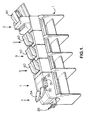
Figure 1 is a perspective view of a paper handling apparatus according to the present invention; -
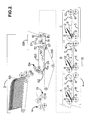
Figure 2 is a schematic representation of the paper handling apparatus ofFigure 1 ; -
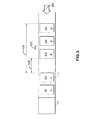
Figure 3 is a diagram illustrating details of the invention. - The paper handling apparatus 1 comprises a collation and inserter station I into which all the documents are ultimately fed from any one or any combination of feeder stations A, B, C and D.
- Each feeder station A, B, C, D comprises a
document holding hopper 40. A series of conveyors and sensors links the feeder stations and are described in more detail with reference toFigure 2 . - A
control panel 31 is positioned towards the collation station I and comprises an array ofkeys 32 and adisplay 33 for use by a machine operator to enter operating parameters such as the choice of prime document feeder station, whether inserts are selected manually and from which stations. The operator can alternatively choose that the selection is made automatically, for example by reading a bar code or other markings on the prime document. Thecontrol panel 31 may alternatively comprise a PC with a monitor and keyboard, for example mounted above the collator I. - In the example shown in
Figure 1 , station D is chosen as the prime document feeder station. This comprises at least oneholding hopper 40, a prime document collator for when the prime document consists of more than one sheet of paper, and a folder to reduce the footprint of the prime document to fit into the chosen envelope size. An optical reader may also be incorporated to read coding on the prime document for control and statistical purposes. - As shown in detail in
Figure 2 each feeder station A, B, C comprises, downstream of the respectivedocument holding hopper 40 shown inFigure 1 , an exit hold point platform 2. A sensor (not shown) may be located on or adjacent the platform 2. A conveyor system 4 links the feeder stations and comprises a series of adjacently located conveyor tracks bridging the gaps between each of the feeder stations A, B, C and D and the collation station I. The tracks each comprise alower conveyor belt 5 which passes overrollers 6 and an upper conveyor belt 9 which passes overrollers 10. Thebelts 5, 9 are continuously running. Many arrangements for driving and tensioning the belts will be evident to skilled persons. - A track control sensor (not shown) may be located adjacent each pair of
conveyor belts 5, 9 in the vicinity of the subsequent feeder station. Rollers 8 control the exit of a document from respective feeder platforms 2 and are selectively driven by a control means. Acontrol idler roller 11 is movable to control the tension in the upper conveyor belt 9. In practice this may be mounted on a pivoted arm. -
Arrows 12 show the direction of feed of documents from thehoppers 40 inFigure 1 to the platform 2 of each feeder station andarrow 13 shows the direction of movement of documents along the conveyor system. Between feeder station A and collation station I is a further double conveyor belt system comprisinglower conveyor belt 14 driven by rollers 15 and upper conveyor belt 16 driven byrollers 17. - A collator in-feed sensor (not shown) may be located at the exit of this
double conveyor 14/16. - Independently engageable clutches, or other means for varying the speed of rollers and thus of conveyor belts can be utilized and will be evident to a person skilled in the art.
- The collation and insertion station I has an
input section 58 and acollate pocket 50 having input rollers 51. Aninsert drive pawl 57 which is mounted to an insertpawl track chain 56 pushes collated documents out of thecollate pocket 50 at appropriate intervals and into anenvelope 52 located at the exit to thecollate pocket 50. Envelopes are stored inenvelope hopper 53 and are fed one at a time into theenvelope holding section 54 where the envelope flap is held between the rollers and the envelope mouth is held open byfingers 24 for insertion of the collated group of documents. - Different documents may be put into the hoppers of each of the feeding stations A, B C and D and are fed one at a time, or in packs of several documents of the same type, to the respective feed platforms 2. In feeding the document to the feed platform, any intelligent information can be read by scanners, the lengths of documents can be measured and the position of both the leading edge and trailing edge registered to the reference position of the feed platform.
- When all of the relevant documents to form a group to be inserted into an envelope have reached the collation station I, they rest on
collation platform 30. The group of documents is typically also decelerated by switching roller speeds as the final portion of the group is released by the input rollers 51 slowly. - The
insert drive pawl 57 then pushes the completed collated group into the envelope while a second group of documents is being formed. In this manner the cycle repeats and further groups are continuously created. - The flap of the envelope is then wetted in a
wetter 13 and moved to anoutput module 14 where the flap is sealed and the envelope prepared for mailing. - The present invention provides active feedback control from later stages of the system to control the separation of documents fed on to the
conveyors 4 and 10 to optimise the speed and efficiency of the system. - The inventor has identified three important criteria in the system and the invention monitors the cycling times of sections of the apparatus and particularly of the post collation sections such as the wetter, the output, the envelope hopper and the insert pawl track. This is then used to control the timing of parts of the apparatus to ensure that the apparatus can run continuously without unscheduled stoppages due to packs being too close together.
- These three important criteria are illustrated in
Figure 3 which schematically shows a conveyor track 60 feeding packs ofdocuments 61 to 65 in the direction ofarrow 66 towardhead unit 67 which in this example is the collating station I ofFigures 1 and2 . Thepacks 61 to 65 are travelling serially butpacks Packs 63 to 65 are to be collated into a second group denoted by the letter B and inserted into another envelope. - The important criteria are:
- 101. The minimum gap between the trailing edge of the
last pack 62 in one group A to the trailing edge of thelast pack 65 in the following group B, i.e. the minimum gap between the last pack in a group and the last pack in the following group. - 102. The minimum gap between the trailing edge of one
pack 63 to the leading edge of thefollowing pack 64 within the same group B, i.e. the gap between 2 packs within the same group. - 103. The minimum gap between the trailing edge of one group A to the leading edge of the following group B, i.e. the gap between the
last pack 62 of one group A and thefirst pack 63 of the following group B, i.e. the gap between the last pack in a group and the first pack of the next group. -
Gap 101 is controlled in dependence upon the slowest cycle time of the wetter 13, theoutput 14, theenvelope hopper 53 and theinsert pawl track 56. -
Gap 102 is controlled to match the time it takes for thecollate pocket 50 to receive a pack of documents and to become available to receive a further pack of documents of the same group; taking into account the pack length. -
Gap 103 is determined by the time taken by thecollator 50 to accept the last pack of a group, pass it to theinserter head 54 and be free to accept the first pack of the following group, taking into account the pack length. - Using this system has the advantage of maximising cycling speed and minimising track stoppages. It also automatically copes with user adjustments, envelope sizes, document sizes and the quantity of documents, all of which affect the cycle times of different sections of the system.
Claims (6)
- A paper handling apparatus comprising:a plurality of feeder stations, for feeding documents to a conveyer, means for collating documents into packs, and means for collating packs into groups of documents, and an inserter module for inserting each group into an envelope, further comprising:means for monitoring the cycling and working times of sections of the inserter module, andmeans for determining at least one of:a first desired gap being the minimum gap between trailing edges of consecutive groups;a second desired gap being the minimum gap between the trailing edge of one pack and the leading edge of the following pack;a third desired gap being the minimum gap between the trailing edge of one group to the leading edge of the following group; andmeans for controlling at least one of the feeder stations to achieve at least one of the respective desired gaps, wherein the first desired gap is controlled in dependence upon the slowest cycle time of any one of the wetter, the output, the envelope hopper and the insert pawl track.
- Apparatus according to claim 1 wherein the second desired gap is controlled in dependence upon the time it takes for the group collator to receive a pack and to become available to receive a further pack of the same group; taking into account the pack length.
- Apparatus according to claim 1 or 2, wherein the third desired gap is determined by the time taken by the group collator to accept the last pack of a group, pass it to the inserter head and be free to accept the first pack of the following group, taking into account pack length.
- A method for operating a paper handling apparatus comprising:a plurality of feeder stations, for feeding documents to a conveyer;means for collating documents into packs;means for collating packs into groups of documents; andan inserter module for inserting each group into an envelope, wherein the method comprises:means for monitoring the cycling and working times of sections of the inserter module; anddetermining at least one of:a first desired gap being the minimum gap between trailing edges of consecutive groups;a second desired gap being the minimum gap between the trailing edge of one pack and the leading edge of the following pack;a third desired gap being the minimum gap between the trailing edge of one group to the leading edge of the following group; andcontrolling at least one of the feeder stations to achieve at least one of the respective desired gaps, wherein the first desired gap is controlled in dependence upon the slowest cycle time of any one of the wetter, the output, the envelope hopper and the insert pawl track.
- A method according to claim 4 wherein the second desired gap is controlled in dependence upon the time it takes for the group collator to receive a pack and to become available to receive a further pack of the same group; taking into account the pack length.
- A method according to claim 4 or 5 wherein the third desired gap is determined by the time taken by the group collator to accept the last pack of a group, pass it to the inserter head and be free to accept the first pack of the following group, taking into account pack length.
Applications Claiming Priority (1)
| Application Number | Priority Date | Filing Date | Title |
|---|---|---|---|
| GB0913301A GB2472248A (en) | 2009-07-31 | 2009-07-31 | A paper handling apparatus |
Publications (3)
| Publication Number | Publication Date |
|---|---|
| EP2279975A2 true EP2279975A2 (en) | 2011-02-02 |
| EP2279975A3 EP2279975A3 (en) | 2015-03-04 |
| EP2279975B1 EP2279975B1 (en) | 2017-09-20 |
Family
ID=41067108
Family Applications (1)
| Application Number | Title | Priority Date | Filing Date |
|---|---|---|---|
| EP10171334.5A Active EP2279975B1 (en) | 2009-07-31 | 2010-07-29 | Paper handling apparatus and method for operating a paper handling apparatus |
Country Status (3)
| Country | Link |
|---|---|
| US (1) | US8376120B2 (en) |
| EP (1) | EP2279975B1 (en) |
| GB (1) | GB2472248A (en) |
Family Cites Families (9)
| Publication number | Priority date | Publication date | Assignee | Title |
|---|---|---|---|---|
| DE1611703B1 (en) * | 1967-10-11 | 1972-03-09 | Windmoeller & Hoelscher | Device for dividing a certain number of items within a continuous sequence of sacks or bags formed at the end of a sack or bag machine |
| US6601364B2 (en) * | 1999-08-30 | 2003-08-05 | Pitney Bowes Inc. | Method and device for synchronizing motion for insert feeders in an insertion system |
| US6732011B1 (en) * | 1999-10-04 | 2004-05-04 | Pitney Bowes Inc. | Apparatus for preparation of mailpieces and method for downstream control of such apparatus |
| US6615105B2 (en) * | 2001-10-18 | 2003-09-02 | Pitney Bowes Inc. | System and method for adjusting sheet input to an inserter system |
| GB2389574B (en) * | 2002-06-14 | 2005-07-06 | Pfe Internat Ltd | Collator |
| US7506746B2 (en) * | 2002-08-31 | 2009-03-24 | Applied Materials, Inc. | System for transporting substrate carriers |
| JP4508024B2 (en) * | 2005-07-22 | 2010-07-21 | ブラザー工業株式会社 | Image forming apparatus |
| US7396006B2 (en) * | 2005-10-03 | 2008-07-08 | Bowe Bell + Howell Company | Apparatus for assembly of document sets into a single collated packet |
| US7857297B2 (en) * | 2007-11-30 | 2010-12-28 | Pitney Bowes Inc. | Electrodynamic propulsion system for conveying sheet material |
-
2009
- 2009-07-31 GB GB0913301A patent/GB2472248A/en not_active Withdrawn
-
2010
- 2010-07-29 EP EP10171334.5A patent/EP2279975B1/en active Active
- 2010-07-30 US US12/847,393 patent/US8376120B2/en active Active
Non-Patent Citations (1)
| Title |
|---|
| None |
Also Published As
| Publication number | Publication date |
|---|---|
| US20110024263A1 (en) | 2011-02-03 |
| EP2279975B1 (en) | 2017-09-20 |
| GB0913301D0 (en) | 2009-09-02 |
| EP2279975A3 (en) | 2015-03-04 |
| GB2472248A (en) | 2011-02-02 |
| US8376120B2 (en) | 2013-02-19 |
Similar Documents
| Publication | Publication Date | Title |
|---|---|---|
| US5083769A (en) | Dual collating machine | |
| AU2009288644B2 (en) | Conveying apparatus for envelopes and related methods | |
| EP1911710B1 (en) | Apparatus and methods for staging and processing documents | |
| CA2172617C (en) | Process and device for forming and moving stacks of printed sheets | |
| AU2005257998A1 (en) | Sheet handling apparatus | |
| US6915184B2 (en) | Collator | |
| US5876029A (en) | Feeder assembly apparatus | |
| US20080302068A1 (en) | Envelope filling machine | |
| EP1770042B1 (en) | Apparatus for assembly of document sets into a single collated packet | |
| JPH11193146A (en) | Hopper loader having bow type conveyor forming flow of overlapped signature from vertical stack | |
| US8376120B2 (en) | Paper handling apparatus | |
| EP1067077B1 (en) | Method and device for sheet collation | |
| GB2412104A (en) | Plural parallel conveyors with adjustable relative positions | |
| US8172216B2 (en) | Apparatus and method for gathering documents | |
| JP2023149738A (en) | Booklet making device | |
| EP1683751A2 (en) | Apparatus and method for accumulating sheets | |
| GB2201403A (en) | Buffering feeding system for envelope inserting machine | |
| US20030080486A1 (en) | Inserting machine with interchangeable modules | |
| JPH09142091A (en) | Sealing device | |
| EP2000324B1 (en) | Envelope filling machine | |
| US9096053B2 (en) | Method for sorting mail pieces on a printing press | |
| RU2496705C2 (en) | Device for transfer and positioning of roll articles and method to this end | |
| EP2364943A2 (en) | Apparatus and process for sorting a sequential flow of postal items according to a predetermined criterion and wrapping up the postal items so sorted | |
| JP3746597B2 (en) | Paper supply device | |
| JP2002080014A (en) | Automatic envelope set replacing and collating band applying machine |
Legal Events
| Date | Code | Title | Description |
|---|---|---|---|
| PUAI | Public reference made under article 153(3) epc to a published international application that has entered the european phase |
Free format text: ORIGINAL CODE: 0009012 |
|
| AK | Designated contracting states |
Kind code of ref document: A2 Designated state(s): AL AT BE BG CH CY CZ DE DK EE ES FI FR GB GR HR HU IE IS IT LI LT LU LV MC MK MT NL NO PL PT RO SE SI SK SM TR |
|
| AX | Request for extension of the european patent |
Extension state: BA ME RS |
|
| PUAL | Search report despatched |
Free format text: ORIGINAL CODE: 0009013 |
|
| AK | Designated contracting states |
Kind code of ref document: A3 Designated state(s): AL AT BE BG CH CY CZ DE DK EE ES FI FR GB GR HR HU IE IS IT LI LT LU LV MC MK MT NL NO PL PT RO SE SI SK SM TR |
|
| AX | Request for extension of the european patent |
Extension state: BA ME RS |
|
| RIC1 | Information provided on ipc code assigned before grant |
Ipc: B65H 39/055 20060101ALI20150127BHEP Ipc: B43M 3/04 20060101ALI20150127BHEP Ipc: B65H 39/10 20060101ALI20150127BHEP Ipc: B65H 39/02 20060101ALI20150127BHEP Ipc: B65H 39/043 20060101AFI20150127BHEP Ipc: B65H 33/12 20060101ALI20150127BHEP |
|
| 17P | Request for examination filed |
Effective date: 20150904 |
|
| RBV | Designated contracting states (corrected) |
Designated state(s): AL AT BE BG CH CY CZ DE DK EE ES FI FR GB GR HR HU IE IS IT LI LT LU LV MC MK MT NL NO PL PT RO SE SI SK SM TR |
|
| GRAP | Despatch of communication of intention to grant a patent |
Free format text: ORIGINAL CODE: EPIDOSNIGR1 |
|
| RIC1 | Information provided on ipc code assigned before grant |
Ipc: B65H 39/043 20060101AFI20170411BHEP Ipc: B65H 33/12 20060101ALI20170411BHEP Ipc: B65H 39/02 20060101ALI20170411BHEP Ipc: B43M 3/04 20060101ALI20170411BHEP Ipc: B65H 39/10 20060101ALI20170411BHEP Ipc: B65H 39/055 20060101ALI20170411BHEP |
|
| INTG | Intention to grant announced |
Effective date: 20170518 |
|
| GRAS | Grant fee paid |
Free format text: ORIGINAL CODE: EPIDOSNIGR3 |
|
| GRAA | (expected) grant |
Free format text: ORIGINAL CODE: 0009210 |
|
| AK | Designated contracting states |
Kind code of ref document: B1 Designated state(s): AL AT BE BG CH CY CZ DE DK EE ES FI FR GB GR HR HU IE IS IT LI LT LU LV MC MK MT NL NO PL PT RO SE SI SK SM TR |
|
| REG | Reference to a national code |
Ref country code: GB Ref legal event code: FG4D |
|
| REG | Reference to a national code |
Ref country code: CH Ref legal event code: EP |
|
| REG | Reference to a national code |
Ref country code: AT Ref legal event code: REF Ref document number: 929952 Country of ref document: AT Kind code of ref document: T Effective date: 20171015 |
|
| REG | Reference to a national code |
Ref country code: IE Ref legal event code: FG4D |
|
| REG | Reference to a national code |
Ref country code: DE Ref legal event code: R096 Ref document number: 602010045329 Country of ref document: DE |
|
| REG | Reference to a national code |
Ref country code: DE Ref legal event code: R082 Ref document number: 602010045329 Country of ref document: DE Representative=s name: CBDL PATENTANWAELTE, DE |
|
| REG | Reference to a national code |
Ref country code: NL Ref legal event code: MP Effective date: 20170920 |
|
| PG25 | Lapsed in a contracting state [announced via postgrant information from national office to epo] |
Ref country code: NO Free format text: LAPSE BECAUSE OF FAILURE TO SUBMIT A TRANSLATION OF THE DESCRIPTION OR TO PAY THE FEE WITHIN THE PRESCRIBED TIME-LIMIT Effective date: 20171220 Ref country code: LT Free format text: LAPSE BECAUSE OF FAILURE TO SUBMIT A TRANSLATION OF THE DESCRIPTION OR TO PAY THE FEE WITHIN THE PRESCRIBED TIME-LIMIT Effective date: 20170920 Ref country code: FI Free format text: LAPSE BECAUSE OF FAILURE TO SUBMIT A TRANSLATION OF THE DESCRIPTION OR TO PAY THE FEE WITHIN THE PRESCRIBED TIME-LIMIT Effective date: 20170920 Ref country code: HR Free format text: LAPSE BECAUSE OF FAILURE TO SUBMIT A TRANSLATION OF THE DESCRIPTION OR TO PAY THE FEE WITHIN THE PRESCRIBED TIME-LIMIT Effective date: 20170920 Ref country code: SE Free format text: LAPSE BECAUSE OF FAILURE TO SUBMIT A TRANSLATION OF THE DESCRIPTION OR TO PAY THE FEE WITHIN THE PRESCRIBED TIME-LIMIT Effective date: 20170920 |
|
| REG | Reference to a national code |
Ref country code: LT Ref legal event code: MG4D |
|
| REG | Reference to a national code |
Ref country code: AT Ref legal event code: MK05 Ref document number: 929952 Country of ref document: AT Kind code of ref document: T Effective date: 20170920 |
|
| PG25 | Lapsed in a contracting state [announced via postgrant information from national office to epo] |
Ref country code: BG Free format text: LAPSE BECAUSE OF FAILURE TO SUBMIT A TRANSLATION OF THE DESCRIPTION OR TO PAY THE FEE WITHIN THE PRESCRIBED TIME-LIMIT Effective date: 20171220 Ref country code: LV Free format text: LAPSE BECAUSE OF FAILURE TO SUBMIT A TRANSLATION OF THE DESCRIPTION OR TO PAY THE FEE WITHIN THE PRESCRIBED TIME-LIMIT Effective date: 20170920 Ref country code: GR Free format text: LAPSE BECAUSE OF FAILURE TO SUBMIT A TRANSLATION OF THE DESCRIPTION OR TO PAY THE FEE WITHIN THE PRESCRIBED TIME-LIMIT Effective date: 20171221 |
|
| PG25 | Lapsed in a contracting state [announced via postgrant information from national office to epo] |
Ref country code: NL Free format text: LAPSE BECAUSE OF FAILURE TO SUBMIT A TRANSLATION OF THE DESCRIPTION OR TO PAY THE FEE WITHIN THE PRESCRIBED TIME-LIMIT Effective date: 20170920 |
|
| PG25 | Lapsed in a contracting state [announced via postgrant information from national office to epo] |
Ref country code: ES Free format text: LAPSE BECAUSE OF FAILURE TO SUBMIT A TRANSLATION OF THE DESCRIPTION OR TO PAY THE FEE WITHIN THE PRESCRIBED TIME-LIMIT Effective date: 20170920 Ref country code: PL Free format text: LAPSE BECAUSE OF FAILURE TO SUBMIT A TRANSLATION OF THE DESCRIPTION OR TO PAY THE FEE WITHIN THE PRESCRIBED TIME-LIMIT Effective date: 20170920 Ref country code: CZ Free format text: LAPSE BECAUSE OF FAILURE TO SUBMIT A TRANSLATION OF THE DESCRIPTION OR TO PAY THE FEE WITHIN THE PRESCRIBED TIME-LIMIT Effective date: 20170920 Ref country code: RO Free format text: LAPSE BECAUSE OF FAILURE TO SUBMIT A TRANSLATION OF THE DESCRIPTION OR TO PAY THE FEE WITHIN THE PRESCRIBED TIME-LIMIT Effective date: 20170920 |
|
| PG25 | Lapsed in a contracting state [announced via postgrant information from national office to epo] |
Ref country code: EE Free format text: LAPSE BECAUSE OF FAILURE TO SUBMIT A TRANSLATION OF THE DESCRIPTION OR TO PAY THE FEE WITHIN THE PRESCRIBED TIME-LIMIT Effective date: 20170920 Ref country code: IT Free format text: LAPSE BECAUSE OF FAILURE TO SUBMIT A TRANSLATION OF THE DESCRIPTION OR TO PAY THE FEE WITHIN THE PRESCRIBED TIME-LIMIT Effective date: 20170920 Ref country code: SM Free format text: LAPSE BECAUSE OF FAILURE TO SUBMIT A TRANSLATION OF THE DESCRIPTION OR TO PAY THE FEE WITHIN THE PRESCRIBED TIME-LIMIT Effective date: 20170920 Ref country code: AT Free format text: LAPSE BECAUSE OF FAILURE TO SUBMIT A TRANSLATION OF THE DESCRIPTION OR TO PAY THE FEE WITHIN THE PRESCRIBED TIME-LIMIT Effective date: 20170920 Ref country code: SK Free format text: LAPSE BECAUSE OF FAILURE TO SUBMIT A TRANSLATION OF THE DESCRIPTION OR TO PAY THE FEE WITHIN THE PRESCRIBED TIME-LIMIT Effective date: 20170920 Ref country code: IS Free format text: LAPSE BECAUSE OF FAILURE TO SUBMIT A TRANSLATION OF THE DESCRIPTION OR TO PAY THE FEE WITHIN THE PRESCRIBED TIME-LIMIT Effective date: 20180120 |
|
| REG | Reference to a national code |
Ref country code: DE Ref legal event code: R097 Ref document number: 602010045329 Country of ref document: DE |
|
| REG | Reference to a national code |
Ref country code: FR Ref legal event code: PLFP Year of fee payment: 9 |
|
| PLBE | No opposition filed within time limit |
Free format text: ORIGINAL CODE: 0009261 |
|
| STAA | Information on the status of an ep patent application or granted ep patent |
Free format text: STATUS: NO OPPOSITION FILED WITHIN TIME LIMIT |
|
| PG25 | Lapsed in a contracting state [announced via postgrant information from national office to epo] |
Ref country code: DK Free format text: LAPSE BECAUSE OF FAILURE TO SUBMIT A TRANSLATION OF THE DESCRIPTION OR TO PAY THE FEE WITHIN THE PRESCRIBED TIME-LIMIT Effective date: 20170920 |
|
| 26N | No opposition filed |
Effective date: 20180621 |
|
| PG25 | Lapsed in a contracting state [announced via postgrant information from national office to epo] |
Ref country code: SI Free format text: LAPSE BECAUSE OF FAILURE TO SUBMIT A TRANSLATION OF THE DESCRIPTION OR TO PAY THE FEE WITHIN THE PRESCRIBED TIME-LIMIT Effective date: 20170920 |
|
| REG | Reference to a national code |
Ref country code: CH Ref legal event code: PL |
|
| PG25 | Lapsed in a contracting state [announced via postgrant information from national office to epo] |
Ref country code: LU Free format text: LAPSE BECAUSE OF NON-PAYMENT OF DUE FEES Effective date: 20180729 Ref country code: MC Free format text: LAPSE BECAUSE OF FAILURE TO SUBMIT A TRANSLATION OF THE DESCRIPTION OR TO PAY THE FEE WITHIN THE PRESCRIBED TIME-LIMIT Effective date: 20170920 |
|
| REG | Reference to a national code |
Ref country code: BE Ref legal event code: MM Effective date: 20180731 |
|
| PG25 | Lapsed in a contracting state [announced via postgrant information from national office to epo] |
Ref country code: CH Free format text: LAPSE BECAUSE OF NON-PAYMENT OF DUE FEES Effective date: 20180731 Ref country code: LI Free format text: LAPSE BECAUSE OF NON-PAYMENT OF DUE FEES Effective date: 20180731 |
|
| REG | Reference to a national code |
Ref country code: IE Ref legal event code: MM4A |
|
| PG25 | Lapsed in a contracting state [announced via postgrant information from national office to epo] |
Ref country code: BE Free format text: LAPSE BECAUSE OF NON-PAYMENT OF DUE FEES Effective date: 20180731 |
|
| PG25 | Lapsed in a contracting state [announced via postgrant information from national office to epo] |
Ref country code: IE Free format text: LAPSE BECAUSE OF NON-PAYMENT OF DUE FEES Effective date: 20180729 |
|
| PG25 | Lapsed in a contracting state [announced via postgrant information from national office to epo] |
Ref country code: MT Free format text: LAPSE BECAUSE OF NON-PAYMENT OF DUE FEES Effective date: 20180729 |
|
| PG25 | Lapsed in a contracting state [announced via postgrant information from national office to epo] |
Ref country code: TR Free format text: LAPSE BECAUSE OF FAILURE TO SUBMIT A TRANSLATION OF THE DESCRIPTION OR TO PAY THE FEE WITHIN THE PRESCRIBED TIME-LIMIT Effective date: 20170920 |
|
| PG25 | Lapsed in a contracting state [announced via postgrant information from national office to epo] |
Ref country code: PT Free format text: LAPSE BECAUSE OF FAILURE TO SUBMIT A TRANSLATION OF THE DESCRIPTION OR TO PAY THE FEE WITHIN THE PRESCRIBED TIME-LIMIT Effective date: 20170920 Ref country code: HU Free format text: LAPSE BECAUSE OF FAILURE TO SUBMIT A TRANSLATION OF THE DESCRIPTION OR TO PAY THE FEE WITHIN THE PRESCRIBED TIME-LIMIT; INVALID AB INITIO Effective date: 20100729 |
|
| PG25 | Lapsed in a contracting state [announced via postgrant information from national office to epo] |
Ref country code: CY Free format text: LAPSE BECAUSE OF FAILURE TO SUBMIT A TRANSLATION OF THE DESCRIPTION OR TO PAY THE FEE WITHIN THE PRESCRIBED TIME-LIMIT Effective date: 20170920 Ref country code: MK Free format text: LAPSE BECAUSE OF NON-PAYMENT OF DUE FEES Effective date: 20170920 |
|
| PG25 | Lapsed in a contracting state [announced via postgrant information from national office to epo] |
Ref country code: AL Free format text: LAPSE BECAUSE OF FAILURE TO SUBMIT A TRANSLATION OF THE DESCRIPTION OR TO PAY THE FEE WITHIN THE PRESCRIBED TIME-LIMIT Effective date: 20170920 |
|
| REG | Reference to a national code |
Ref country code: DE Ref legal event code: R082 Ref document number: 602010045329 Country of ref document: DE Representative=s name: CBDL PATENTANWAELTE GBR, DE Ref country code: DE Ref legal event code: R082 Ref document number: 602010045329 Country of ref document: DE Representative=s name: CBDL PATENTANWAELTE EGBR, DE |
|
| PGFP | Annual fee paid to national office [announced via postgrant information from national office to epo] |
Ref country code: DE Payment date: 20250722 Year of fee payment: 16 |
|
| PGFP | Annual fee paid to national office [announced via postgrant information from national office to epo] |
Ref country code: GB Payment date: 20250722 Year of fee payment: 16 |
|
| PGFP | Annual fee paid to national office [announced via postgrant information from national office to epo] |
Ref country code: FR Payment date: 20250725 Year of fee payment: 16 |