EP2279965A1 - Compound container and pouring-out method - Google Patents
Compound container and pouring-out method Download PDFInfo
- Publication number
- EP2279965A1 EP2279965A1 EP09735976A EP09735976A EP2279965A1 EP 2279965 A1 EP2279965 A1 EP 2279965A1 EP 09735976 A EP09735976 A EP 09735976A EP 09735976 A EP09735976 A EP 09735976A EP 2279965 A1 EP2279965 A1 EP 2279965A1
- Authority
- EP
- European Patent Office
- Prior art keywords
- container
- accommodation chamber
- main body
- contents
- pouring
- Prior art date
- Legal status (The legal status is an assumption and is not a legal conclusion. Google has not performed a legal analysis and makes no representation as to the accuracy of the status listed.)
- Granted
Links
- 150000001875 compounds Chemical class 0.000 title claims abstract description 57
- 238000000034 method Methods 0.000 title claims description 30
- 230000004308 accommodation Effects 0.000 claims abstract description 116
- 238000005520 cutting process Methods 0.000 claims abstract description 69
- 238000007789 sealing Methods 0.000 claims abstract description 66
- 238000005192 partition Methods 0.000 claims abstract description 63
- 230000002093 peripheral effect Effects 0.000 claims description 73
- 239000007788 liquid Substances 0.000 claims description 51
- 238000002360 preparation method Methods 0.000 claims description 21
- 239000000463 material Substances 0.000 claims description 18
- 239000003153 chemical reaction reagent Substances 0.000 claims description 13
- 239000003463 adsorbent Substances 0.000 claims description 8
- 238000002156 mixing Methods 0.000 claims description 7
- 238000003756 stirring Methods 0.000 claims description 5
- 239000000126 substance Substances 0.000 claims description 4
- 230000000717 retained effect Effects 0.000 claims 1
- 230000006866 deterioration Effects 0.000 abstract 1
- 125000004122 cyclic group Chemical group 0.000 description 22
- 238000011282 treatment Methods 0.000 description 15
- 239000000706 filtrate Substances 0.000 description 14
- 238000010438 heat treatment Methods 0.000 description 10
- 241000193830 Bacillus <bacterium> Species 0.000 description 8
- 238000000605 extraction Methods 0.000 description 7
- 238000001914 filtration Methods 0.000 description 6
- 230000004544 DNA amplification Effects 0.000 description 5
- 238000007689 inspection Methods 0.000 description 5
- 238000007397 LAMP assay Methods 0.000 description 4
- 241000700605 Viruses Species 0.000 description 4
- 238000006243 chemical reaction Methods 0.000 description 4
- 238000003825 pressing Methods 0.000 description 4
- 108090000623 proteins and genes Proteins 0.000 description 4
- 241000894006 Bacteria Species 0.000 description 3
- 244000052616 bacterial pathogen Species 0.000 description 3
- 230000001717 pathogenic effect Effects 0.000 description 3
- -1 polypropylene Polymers 0.000 description 3
- 241000233866 Fungi Species 0.000 description 2
- XAGFODPZIPBFFR-UHFFFAOYSA-N aluminium Chemical compound [Al] XAGFODPZIPBFFR-UHFFFAOYSA-N 0.000 description 2
- 229910052782 aluminium Inorganic materials 0.000 description 2
- 238000011109 contamination Methods 0.000 description 2
- 238000001514 detection method Methods 0.000 description 2
- 238000009826 distribution Methods 0.000 description 2
- 239000003814 drug Substances 0.000 description 2
- 229940079593 drug Drugs 0.000 description 2
- 238000010448 genetic screening Methods 0.000 description 2
- 208000015181 infectious disease Diseases 0.000 description 2
- 238000005259 measurement Methods 0.000 description 2
- 238000012545 processing Methods 0.000 description 2
- 239000002002 slurry Substances 0.000 description 2
- 238000003860 storage Methods 0.000 description 2
- 229930182556 Polyacetal Natural products 0.000 description 1
- 239000004698 Polyethylene Substances 0.000 description 1
- 239000004743 Polypropylene Substances 0.000 description 1
- 239000002250 absorbent Substances 0.000 description 1
- 230000002745 absorbent Effects 0.000 description 1
- 210000000170 cell membrane Anatomy 0.000 description 1
- 230000000694 effects Effects 0.000 description 1
- 229920006351 engineering plastic Polymers 0.000 description 1
- 230000002068 genetic effect Effects 0.000 description 1
- 230000036039 immunity Effects 0.000 description 1
- 238000003018 immunoassay Methods 0.000 description 1
- 230000001771 impaired effect Effects 0.000 description 1
- 230000000415 inactivating effect Effects 0.000 description 1
- 239000004615 ingredient Substances 0.000 description 1
- 238000001746 injection moulding Methods 0.000 description 1
- 238000009434 installation Methods 0.000 description 1
- 239000012528 membrane Substances 0.000 description 1
- 244000005700 microbiome Species 0.000 description 1
- 239000000203 mixture Substances 0.000 description 1
- 238000012986 modification Methods 0.000 description 1
- 230000004048 modification Effects 0.000 description 1
- 108020004707 nucleic acids Proteins 0.000 description 1
- 150000007523 nucleic acids Chemical class 0.000 description 1
- 102000039446 nucleic acids Human genes 0.000 description 1
- 239000005022 packaging material Substances 0.000 description 1
- 238000012856 packing Methods 0.000 description 1
- 229920001707 polybutylene terephthalate Polymers 0.000 description 1
- 229920000573 polyethylene Polymers 0.000 description 1
- 229920005672 polyolefin resin Polymers 0.000 description 1
- 229920006324 polyoxymethylene Polymers 0.000 description 1
- 229920001155 polypropylene Polymers 0.000 description 1
- 230000002265 prevention Effects 0.000 description 1
- 239000000047 product Substances 0.000 description 1
- 239000011369 resultant mixture Substances 0.000 description 1
- 239000007787 solid Substances 0.000 description 1
- 239000000243 solution Substances 0.000 description 1
- 238000012360 testing method Methods 0.000 description 1
- 229920005992 thermoplastic resin Polymers 0.000 description 1
- 241000712461 unidentified influenza virus Species 0.000 description 1
Images


Classifications
-
- B—PERFORMING OPERATIONS; TRANSPORTING
- B65—CONVEYING; PACKING; STORING; HANDLING THIN OR FILAMENTARY MATERIAL
- B65D—CONTAINERS FOR STORAGE OR TRANSPORT OF ARTICLES OR MATERIALS, e.g. BAGS, BARRELS, BOTTLES, BOXES, CANS, CARTONS, CRATES, DRUMS, JARS, TANKS, HOPPERS, FORWARDING CONTAINERS; ACCESSORIES, CLOSURES, OR FITTINGS THEREFOR; PACKAGING ELEMENTS; PACKAGES
- B65D47/00—Closures with filling and discharging, or with discharging, devices
- B65D47/04—Closures with discharging devices other than pumps
- B65D47/06—Closures with discharging devices other than pumps with pouring spouts or tubes; with discharge nozzles or passages
-
- B—PERFORMING OPERATIONS; TRANSPORTING
- B65—CONVEYING; PACKING; STORING; HANDLING THIN OR FILAMENTARY MATERIAL
- B65D—CONTAINERS FOR STORAGE OR TRANSPORT OF ARTICLES OR MATERIALS, e.g. BAGS, BARRELS, BOTTLES, BOXES, CANS, CARTONS, CRATES, DRUMS, JARS, TANKS, HOPPERS, FORWARDING CONTAINERS; ACCESSORIES, CLOSURES, OR FITTINGS THEREFOR; PACKAGING ELEMENTS; PACKAGES
- B65D51/00—Closures not otherwise provided for
- B65D51/18—Arrangements of closures with protective outer cap-like covers or of two or more co-operating closures
- B65D51/20—Caps, lids, or covers co-operating with an inner closure arranged to be opened by piercing, cutting, or tearing
- B65D51/22—Caps, lids, or covers co-operating with an inner closure arranged to be opened by piercing, cutting, or tearing having means for piercing, cutting, or tearing the inner closure
- B65D51/221—Caps, lids, or covers co-operating with an inner closure arranged to be opened by piercing, cutting, or tearing having means for piercing, cutting, or tearing the inner closure a major part of the inner closure being left inside the container after the opening
- B65D51/222—Caps, lids, or covers co-operating with an inner closure arranged to be opened by piercing, cutting, or tearing having means for piercing, cutting, or tearing the inner closure a major part of the inner closure being left inside the container after the opening the piercing or cutting means being integral with, or fixedly attached to, the outer closure
-
- B—PERFORMING OPERATIONS; TRANSPORTING
- B65—CONVEYING; PACKING; STORING; HANDLING THIN OR FILAMENTARY MATERIAL
- B65D—CONTAINERS FOR STORAGE OR TRANSPORT OF ARTICLES OR MATERIALS, e.g. BAGS, BARRELS, BOTTLES, BOXES, CANS, CARTONS, CRATES, DRUMS, JARS, TANKS, HOPPERS, FORWARDING CONTAINERS; ACCESSORIES, CLOSURES, OR FITTINGS THEREFOR; PACKAGING ELEMENTS; PACKAGES
- B65D51/00—Closures not otherwise provided for
- B65D51/18—Arrangements of closures with protective outer cap-like covers or of two or more co-operating closures
- B65D51/20—Caps, lids, or covers co-operating with an inner closure arranged to be opened by piercing, cutting, or tearing
- B65D51/22—Caps, lids, or covers co-operating with an inner closure arranged to be opened by piercing, cutting, or tearing having means for piercing, cutting, or tearing the inner closure
- B65D51/221—Caps, lids, or covers co-operating with an inner closure arranged to be opened by piercing, cutting, or tearing having means for piercing, cutting, or tearing the inner closure a major part of the inner closure being left inside the container after the opening
- B65D51/226—Caps, lids, or covers co-operating with an inner closure arranged to be opened by piercing, cutting, or tearing having means for piercing, cutting, or tearing the inner closure a major part of the inner closure being left inside the container after the opening the piercing or cutting means being non integral with, or not fixedly attached to, the outer closure
- B65D51/227—Caps, lids, or covers co-operating with an inner closure arranged to be opened by piercing, cutting, or tearing having means for piercing, cutting, or tearing the inner closure a major part of the inner closure being left inside the container after the opening the piercing or cutting means being non integral with, or not fixedly attached to, the outer closure and further comprising a device first inhibiting displacement of the piercing or cutting means
-
- B—PERFORMING OPERATIONS; TRANSPORTING
- B65—CONVEYING; PACKING; STORING; HANDLING THIN OR FILAMENTARY MATERIAL
- B65D—CONTAINERS FOR STORAGE OR TRANSPORT OF ARTICLES OR MATERIALS, e.g. BAGS, BARRELS, BOTTLES, BOXES, CANS, CARTONS, CRATES, DRUMS, JARS, TANKS, HOPPERS, FORWARDING CONTAINERS; ACCESSORIES, CLOSURES, OR FITTINGS THEREFOR; PACKAGING ELEMENTS; PACKAGES
- B65D51/00—Closures not otherwise provided for
- B65D51/24—Closures not otherwise provided for combined or co-operating with auxiliary devices for non-closing purposes
- B65D51/28—Closures not otherwise provided for combined or co-operating with auxiliary devices for non-closing purposes with auxiliary containers for additional articles or materials
- B65D51/2807—Closures not otherwise provided for combined or co-operating with auxiliary devices for non-closing purposes with auxiliary containers for additional articles or materials the closure presenting means for placing the additional articles or materials in contact with the main contents by acting on a part of the closure without removing the closure, e.g. by pushing down, pulling up, rotating or turning a part of the closure, or upon initial opening of the container
- B65D51/2814—Closures not otherwise provided for combined or co-operating with auxiliary devices for non-closing purposes with auxiliary containers for additional articles or materials the closure presenting means for placing the additional articles or materials in contact with the main contents by acting on a part of the closure without removing the closure, e.g. by pushing down, pulling up, rotating or turning a part of the closure, or upon initial opening of the container the additional article or materials being released by piercing, cutting or tearing an element enclosing it
- B65D51/2842—Closures not otherwise provided for combined or co-operating with auxiliary devices for non-closing purposes with auxiliary containers for additional articles or materials the closure presenting means for placing the additional articles or materials in contact with the main contents by acting on a part of the closure without removing the closure, e.g. by pushing down, pulling up, rotating or turning a part of the closure, or upon initial opening of the container the additional article or materials being released by piercing, cutting or tearing an element enclosing it said element being provided with a preformed weakened line
- B65D51/285—Closures not otherwise provided for combined or co-operating with auxiliary devices for non-closing purposes with auxiliary containers for additional articles or materials the closure presenting means for placing the additional articles or materials in contact with the main contents by acting on a part of the closure without removing the closure, e.g. by pushing down, pulling up, rotating or turning a part of the closure, or upon initial opening of the container the additional article or materials being released by piercing, cutting or tearing an element enclosing it said element being provided with a preformed weakened line ruptured by a sharp element, e.g. a cutter or a piercer
-
- B—PERFORMING OPERATIONS; TRANSPORTING
- B65—CONVEYING; PACKING; STORING; HANDLING THIN OR FILAMENTARY MATERIAL
- B65D—CONTAINERS FOR STORAGE OR TRANSPORT OF ARTICLES OR MATERIALS, e.g. BAGS, BARRELS, BOTTLES, BOXES, CANS, CARTONS, CRATES, DRUMS, JARS, TANKS, HOPPERS, FORWARDING CONTAINERS; ACCESSORIES, CLOSURES, OR FITTINGS THEREFOR; PACKAGING ELEMENTS; PACKAGES
- B65D2251/00—Details relating to container closures
- B65D2251/0003—Two or more closures
- B65D2251/0006—Upper closure
- B65D2251/0025—Upper closure of the 47-type
-
- B—PERFORMING OPERATIONS; TRANSPORTING
- B65—CONVEYING; PACKING; STORING; HANDLING THIN OR FILAMENTARY MATERIAL
- B65D—CONTAINERS FOR STORAGE OR TRANSPORT OF ARTICLES OR MATERIALS, e.g. BAGS, BARRELS, BOTTLES, BOXES, CANS, CARTONS, CRATES, DRUMS, JARS, TANKS, HOPPERS, FORWARDING CONTAINERS; ACCESSORIES, CLOSURES, OR FITTINGS THEREFOR; PACKAGING ELEMENTS; PACKAGES
- B65D2251/00—Details relating to container closures
- B65D2251/0003—Two or more closures
- B65D2251/0068—Lower closure
- B65D2251/0093—Membrane
- B65D2251/0096—Membrane integral with the container
-
- Y—GENERAL TAGGING OF NEW TECHNOLOGICAL DEVELOPMENTS; GENERAL TAGGING OF CROSS-SECTIONAL TECHNOLOGIES SPANNING OVER SEVERAL SECTIONS OF THE IPC; TECHNICAL SUBJECTS COVERED BY FORMER USPC CROSS-REFERENCE ART COLLECTIONS [XRACs] AND DIGESTS
- Y10—TECHNICAL SUBJECTS COVERED BY FORMER USPC
- Y10T—TECHNICAL SUBJECTS COVERED BY FORMER US CLASSIFICATION
- Y10T436/00—Chemistry: analytical and immunological testing
- Y10T436/25—Chemistry: analytical and immunological testing including sample preparation
- Y10T436/2575—Volumetric liquid transfer
Abstract
Description
- The invention relates to a compound container capable of mixing the contents of a plurality of accommodation chamber formed in the container, while effectively avoiding the leakage of the contents to the outside environment. In particular, the invention relates to a compound container which can, when treating contents in a sealed container, effectively prevent the leakage of the contents to be heated to the outside environment during this treatment without causing the sealing performance of the container to be deteriorated, and the method for pouring a predetermined amount of a sample preparation liquid out of this compound container.
- In genetic screening in the fields of medical treatments or medicines, several techniques of detecting the existence of pathogenic bacteria from the sample extracted from a subject's body are known. Of these techniques, a gene amplification method, known as the LAMP method has come to attract attention, which is capable of facilitating the detection in which the gene DNA of the extracted pathogenic bacteria and a predetermined reagent are mixed, and the resultant mixture is incubated at a predetermined temperature, thereby to amplify the target DNA (Non-Patent Document 1).
By such a gene amplification method, as compared with the conventional genetic screening, not only the inspection time is shortened, but also the presence of the target gene can be visually judged since a significantly large amount of amplified products are obtained, whereby simplification of the inspection has been attained. -
Patent Document 1 discloses a sample extraction liquid container which prepares a sample extraction liquid to be dripped to a reaction reagent for detecting viruses, such as influenza virus. -
- Non-Patent Document 1: Virus,
- Patent Document 1:
JP-A-2008-26090 - Meanwhile, in the above-mentioned gene amplification method, when the gene to be amplified is the one derived from pathogenic bacteria involving the risk of aerial infection, like tubercle bacillus, there were the following problems.
- For example, during the process in which a sample containing tubercle bacillus and a predetermined reagent are mixed, and the resulting mixture is heated at a fixed temperature to extract a target gene, if this treatment is conducted in a container with its mouth being opened, the container may be toppled accidentally to cause the contents to be spilled over or to cause tubercle bacillus to be dispersed in the air from the opened mouth of the container. In such a case, a tester may be exposed to the risk of being infected with tubercle bacillus. That is, a tester's safety was not ensured.
- On the other hand, in the sample extraction liquid container disclosed in
Patent Document 1, it is possible to prepare a sample with the container being sealed, as well as to add the sample extraction liquid dropwise to the reaction reagent container, while filtering unnecessary ingredients, whereby the risk of contamination or infection when preparing a sample extraction liquid can be prevented. - However, in
Patent Document 1, preparation of the sample liquid is completed only by immersing a sample collected from a patient in a solution, extracting, followed by filtering. The technique disclosed inPatent Document 1 does not take into consideration at all the case where the sample in the container is heated together with the container. Therefore, if the container inPatent Document 1 is applied to the above-mentioned gene amplification method as it is, the cylindrical container formed of a flexible material may be subjected to thermal deformation during the heat treatment, and the sealing performance thereof may be deteriorated. Therefore, a problem still exists that the contents are leaked to the outside environment. - The invention has been made in view of the above-mentioned circumstances. An object of the invention is to provide, when, for example, processing contents which are needed to be heat-treated by heating it together with the container or the like, while keeping the state where the contents are sealed within the container, a compound container which is capable of mixing the contents sealed in a plurality of accommodation chambers formed in the container while effectively avoiding the leakage of the contents to be heated to the outside environment, as well as a pouring method for pouring a predetermined amount of a sample preparation liquid from the compound container.
- The compound container according to the invention has a configuration in which the container at least comprises a container main body forming a first accommodation chamber and an auxiliary container forming a second accommodation chamber, wherein a mounting part on which the auxiliary container is mounted is provided in the container main body and a cutting part which cuts a second accommodation chamber partition wall which partitions part of the second accommodation chamber formed in the auxiliary container is formed, and when the auxiliary container is mounted on the container main body, the second accommodation chamber partition wall is cut, whereby the first accommodation chamber and the second accommodation chamber are intercommunicated.
- The compound container according to the invention has a configuration, in order to enable the contents to be taken out from the first accommodation chamber, in which the contents outlet port is provided in the container main body and an opening pouring element to be mounted on the contents output port is provided, the opening pouring element is provided with a cutting part which cuts a first accommodation chamber partition wall which partitions part of the first accommodation chamber formed in the container main body, and when the opening pouring element is installed on the container main body, the first accommodation chamber partition wall is cut.
- A pouring method according to the invention is a method in which, when pouring out from the pouring port a sample preparation liquid obtained by preparing a sample which has been collected from a subject by using the above-mentioned compound container and dripping the sample preparation liquid to a predetermined dropping container, a positioning means is provided for positioning the front end of the pouring port so that the distance between the front end of the pouring port and the inner bottom surface of the dripping container becomes constant when the pouring mouth is inserted into the dropping container, and on the dropping container, a liquid level line indicating at least the lower limit of the predetermined amount is displayed and, after positioning the front end of the pouring port while inserting the pouring port into the dropping container, the container main body is squeezed to allow the sample preparation liquid to be poured until the amount of the liquid which has been poured exceeds the liquid level line showing the lower limit, and while keeping the positioned state, the container main body is restored to suck the sample preparation liquid which has been excessively poured when the liquid level of the sample preparation liquid which has been poured exceeds the front end of the pouring port thus positioned, thereby allowing an adequate amount of a sample preparation liquid to be poured.
- According to the compound container of the invention, the final extraction of the contents is conducted on the container main body side, and hence the auxiliary container can be designed only by noting the sealing performance thereof. For this reason, it is easy to allow the auxiliary container to have a structure which is surely sealed so that the contents may not be leaked outside, and the sealing performance thereof may not be impaired when the auxiliary container is subjected to any treatments separately from the container main body. As a result, the contents sealed within the accommodation chamber formed in each of the container main bodies and the auxiliary container can be mixed while keeping the state where they are isolated from the outside environment.
-
-
FIG. 1 is a schematic exploded view showing the first embodiment of the compound container according to the invention; -
FIG. 2 is an exploded cross-sectional view showing the first embodiment of the compound container according to the invention; -
FIG. 3 is an explanatory view showing an example in which a sealing element and a protecting element are installed in the container main body shown inFIG. 1 ; -
FIG. 4 is an explanatory view noting the contents outlet port of the container main body shown inFIG. 1 ; -
FIG. 5 is a plan view of an opening pouring element shown inFIG. 1 ; -
FIG. 6 is an exploded cross-sectional view of the opening pouring element shown inFIG. 1 ; -
FIG. 7 is an explanatory view showing a step in the use example of the compound container according to the first embodiment of the invention; -
FIG. 8 is an explanatory view showing a step in the use example of the compound container according to the first embodiment of the invention; -
FIG. 9 is an explanatory view showing a step in the use example of the compound container according to the first embodiment of the invention; -
FIG. 10 is an explanatory view showing the form at the time of conducting a disposal treatment of the inspection container according to the first embodiment of the invention; -
FIG. 11 is a schematic exploded view showing the second embodiment of the compound container of the invention; -
FIG. 12 is a schematic exploded view showing the second embodiment of the compound container of the invention; -
FIG. 13 is an explanatory view showing an example in which a sealing element and a protecting element are installed in the container main body shown inFIG. 11 ; -
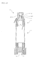
FIG. 14 is a plan view showing the opening pouring element shown inFIG. 11 as viewed from the side of the pouring port; -
FIG. 15 is an exploded cross-sectional view of the opening pouring element shown inFIG. 11 ; -
FIG. 16 is an explanatory view showing one step in the use example according to the second embodiment of the compound container of the invention; -
FIG. 17 is an explanatory view showing one step in the use example according to the second embodiment of the compound container of the invention; -
FIG. 18 is an explanatory view showing one step in the use example according to the second embodiment of the compound container of the invention; -
FIG. 19 is an explanatory view showing one step of sealing a filtrate which has been added dropwise to a dropping container according to the second embodiment of the compound container of the invention; and -
FIG. 20 is an explanatory view showing the form at the time of conducting a disposal treatment of the inspection container according to the second embodiment of the invention. - The preferable embodiment of the invention will be described with reference to the drawings.
- The first embodiment of the invention will be explained.
FIG. 1 is an exploded view showing the outline of one example of the compound container according to this embodiment.FIG. 2 is a cross-sectional view obtained by cutting by a plane which is in parallel with the paper including the central axis indicated by a dashed line inFIG. 1 . - First, the outline of the compound container according to this embodiment will be explained. In the example shown in
FIG. 1 andFIG. 2 , thecompound container 1 is comprised of the containermain body 2 which forms thefirst accommodation chamber 20, theauxiliary container 3 forming thesecond accommodation chamber 30, and the opening pouringelement 4.
Moreover, when using thecompound container 1, theauxiliary container 3 is mounted on themounting part 22 of the containermain body 2, and the opening pouringelement 4 is mounted on thecontents outlet port 23 of the containermain body 2. At the time of distribution and storage before use, as shown inFIG. 3 , asealing element 5 is attached to themounting part 22 of the containermain body 2, and a protectingelement 6 is attached to thecontents output port 23 of the containermain body 2.
FIG. 3 is an explanatory view showing the state in which contents S3 are accommodated in the containermain body 2 shown inFIG. 1 and the containermain body 2 is sealed with apouring element 5 and the protectingelement 6 is attached to thecontents outlet port 23. - As mentioned above, the
compound container 1 according to this embodiment is comprised of five elements; that is, the containermain body 2, theauxiliary container 3, theopening pouring element 4, thesealing element 5 and the protectingelement 6.
In this embodiment, these elements can be produced by injection molding etc., for example, by using thermoplastic resin materials such as polyolefin-based resins, the specific examples of which include polypropylene and polyethylene and engineering plastics such as polyacetal and polybutylene terephthalate. Each member may be produced by using the same material. However, according to the difference in function or the like which is required for each element, the material to be used may be differed appropriately. Each element may be colored for light-shielding purpose. In order to allow the accommodated contents to be visible from the outside, each element may be transparent or semi-transparent. - Next, the detailed structure of each of the above-mentioned elements will be explained mainly and in the order of the
auxiliary container 3, the containermain body 2 and theopening pouring element 4. - The
auxiliary container 3 is provided with acylindrical trunk part 31 in which one end side (the upper side in the figure) is rendered as the opening part and the other end side (the lower side in the figure) is blocked by a second accommodationchamber partition wall 30a which partitions part of thesecond accommodation chamber 30 and alid 32 which seals thesecond accommodation chamber 30 partitioned by thetrunk part 31 and the second accommodationchamber partition wall 30a. - As shown in the figure, in the second accommodation
chamber partition wall 30a, the peripheral edge which is in contact with the inner surface of thetrunk part 31 is rendered thin. When theauxiliary container 3 is mounted on the mountingpart 22 of the containermain body 2, it is cut by a cuttingpart 221 formed on the mountingpart 22 of the containermain body 2, mentioned later, along the thinned peripheral edge.
At this time, it is preferred that the second accommodationchamber partition wall 30a be not separated from thetrunk part 31 and dropped. More specifically, it is preferred that the second accommodationchamber partition wall 30a which has been cut be disposed between the inner surface of thetrunk part 31 and the cuttingpart 221 formed on the side of the containermain body 2, while keeping the state in which the second accommodationchamber partition wall 30a is partially connected with the inner surface of the trunk part 31 (seeFIG. 8 (c) or the like given later). - For this purpose, it suffices that a relief part be formed by narrowing the outer diameter of the side of the cutting
part 221 nearer to the front end, and the position at which the second accommodationchamber partition wall 30a is formed be determined so that the second accommodationchamber partition wall 30a is disposed in a gap formed between this relief part and the inner surface of thetrunk part 31, while keeping the state where it is partially connected to the inner surface of thetrunk part 31, taking into consideration the dimension or the like of the cuttingpart 221 formed on the side of the containermain body 2. In the shown example, the second accommodationchamber partition wall 30a is formed in the position which is directed inwardly for a predetermined length from the front end portion of the other end of thetrunk part 31, taking into consideration the relative positional relationship with the cuttingpart 221 formed in the side of the containermain body 2 when theauxiliary container 3 is mounted on the mountingpart 22 of the containermain body 2.
Here, a part ranging from the position where the second accommodationroom partition wall 30a is formed to the front end portion of the other end of thetrunk part 31 will be referred to as the cylindricalpendent part 312. - The
lid 32 is detachably attached to the opening of thetrunk part 31, thereby to seal thesecond accommodation chamber 30 formed in theauxiliary container 3 so that the accommodated contents may not be leaked outside.
In the shown example, thelid 32 is formed of an outercylindrical part 321, an innercylindrical part 322, and atop plate part 323. A thread part is formed on the outer peripheral surface on the opening portion side of thetrunk part 31 and on the inner peripheral surface of the outercylindrical part 321 of thelid 32, whereby thelid 32 is attached to thetrunk part 31 by thread engagement. At the same time, when thelid 32 is attached to thetrunk part 31, the outer peripheral surface of the innercylindrical part 322 is allowed to be in close contact with the inner peripheral surface of thetrunk part 31, thereby to enhance the sealing performance thereof.
In addition, in the shown example, thelid 32 is allowed to be attached to thetrunk part 31 by the thread engagement. Methods for attaching thelid 32 to thetrunk part 31 may be replaced by suitable alternative methods such as capping. - Furthermore, in order to improve sealing performance when the
lid 32 is attached to thetrunk part 31, it is preferred that cyclic projections which contact the front end surface of the peripheral edge of thetrunk part 31 be formed in the corresponding position on the side of thelid 32. In this way, even if the contents are leaked from a gap between the outer peripheral surface of the innercylindrical part 322 and the inner peripheral surface of thetrunk part 31, further leakage can be prevented by the front end surface of the peripheral edge of the opening part of.thetrunk part 31 and the cyclic projections which contact thereto. - Further, by forming a
flange part 311 shown in the figure on the outer peripheral surface of thetrunk part 31 of theauxiliary container 3 along the circumferential direction, not only the rigidity thereof is improved, but also theauxiliary container 3 is prevented from being withdrawn when mounted on the mountingpart 22 of the containermain body 2. Furthermore, by subjecting the outer peripheral surface of the other end side of the trunk part 31 (cylindrical pendant part 312) and the outer peripheral surface of the outercylindrical part 321 of thelid 32 to knuring, these surfaces can serve as an anti-slipping element when thelid 32 is attached to or detached from thetrunk part 31 by thread engagement. - The container
main body 2 has acylindrical trunk part 21. A mountingpart 22 on which theauxiliary container 3 is mounted is provided on the one end side (the upper end side in the figure) of thistrunk part 21. Further, thecontents output mouth 23 is provided in the other end side (the lower end side in the figure) of thetrunk part 21. Theopening pouring element 4 is mounted on thiscontents output port 23.
FIG. 4 is an explanatory view noting thecontents output port 23.Fig. 4(a) is a front view as viewed from the same direction as in the example shown inFIG. 1 .FIG. 4(b) is a side view as viewed from the side when rotated by 90 degrees around the axis from the state shown inFIG. 1 . - The mounting
part 22 is provided with the cuttingpart 221 which cuts the second accommodationchamber partition wall 30a which partitions part of thesecond accommodation chamber 30 formed in theauxiliary container 3 when theauxiliary container 3 is mounted. As shown, thecutting section 221 can be formed into a shape which is obtained by obliquely cutting the front end side of the cylindrical part which rises in parallel with the axial direction, for example. In this way, cutting is started by the intrusion of the front end of the cuttingpart 221 to the second accommodationchamber partition wall 30a when theauxiliary container 3 is mounted on the mountingpart 22. Furthermore, if theauxiliary container 3 is pushed in, the periphery of the second accommodationchamber partition wall 30a is gradually cut. Here, as mentioned above, the outer diameter of part nearer to the front end of the cuttingpart 221 is narrowed, thereby to form a relief part. - Moreover, a
cylindrical sealing tube 222 which rises concentrically with the cuttingpart 221 is formed in the outer peripheral side of thecutting section 221. When mounting theauxiliary container 3 on the mountingpart 22, after the outer peripheral surface of the cuttingpart 221 is in close contact with the inner peripheral surface of thetrunk part 31 of theauxiliary container 3, cutting of the second accommodationchamber partition wall 30a by the cuttingpart 221 is started. Subsequently, the inner peripheral surface of thecylindrical sealing tube 222 is in close contact with the outer peripheral surface of thetrunk part 31 of theauxiliary container 3, and cutting of the second accommodationchamber partition wall 30a is conducted in this state.
Thus, when theauxiliary container 3 is mounted on the mountingpart 22, the outer peripheral surface of thecutting section 221 is in close contact with the inner peripheral surface of thetrunk part 31 of theauxiliary container 3, and the inner peripheral surface of thesealing cylinder 222 is in close contact with the outer peripheral surface of thetrunk part 31 of theauxiliary container 3, whereby thecylindrical pendant part 312 side of theauxiliary container 3 is disposed by the cuttingpart 221 and thesealing cylinder 222. By appropriately adjusting the dimension such as the wall thickness, the sealing performance when theauxiliary container 3 is mounted on the mountingpart 22 and the second accommodationchamber partition wall 30a is cut can be enhanced. - Moreover, the
circular projection 225 which circularly projects along the circumferential direction is formed on the inner peripheral surface of the mountingpart 22. Thiscircular projection 225 is engaged with theflange part 311 formed in thetrunk part 31 of theauxiliary container 3 when theauxiliary container 2 is mounted on the mountingpart 22, thereby preventing theauxiliary container 3 from being dropped. - The mounting
part 22 which is to be provided on the containermain body 2 may be integrally formed with thetrunk part 21. In the shown example, thetrunk part 31 and the mountingpart 22 are provided separately, and the containermain body 2 is formed by attaching the mountingpart 22 to thetrunk part 21.
As mentioned later, when the contents are taken out of thecompound container 1, the containermain body 2 is squeezed, thereby allowing an appropriate amount of the contents to be dripped from a pouringport 411 of the opening pouring member 4 (seeFIG. 9(c) which will be given later). Therefore, it is desired that the containermain body 2 be formed of a flexible material which can be squeezed. When the mountingpart 22 is formed of a flexible material, it may become difficult to ensure the sealing performance for theauxiliary container 3 which is to be mounted on the mountingpart 22. For this reason, in order to form thetrunk part 21 of a flexible material which can be squeezed, and in order to allow the mountingpart 22 to be formed of a relatively hard material taking into consideration the sealing performance with theauxiliary container 3, it is preferred that thetrunk part 21 and the mountingpart 22 be separated. In addition, if the mountingpart 22 is formed of a relatively hard material, the rigidity of the cuttingpart 221 formed in the mountingpart 22 can also be secured. It is preferable to ensure the cutting by thecut section 221 of the second accommodationchamber partition wall 30a of theauxiliary container 3. - In the shown example, the mounting
part 22 has an innercylindrical part 224 which rises on the outer peripheral side of the sealingprojection 222 and is in close contact with the inner peripheral surface of thetrunk part 21, and an outercylindrical part 223 which it is turned back by the front end side of this innercylindrical part 224 and elongates vertically. As shown, the mountingpart 22 has a configuration in which the circular projection formed on the front end side of the inner peripheral surface of the outercylindrical part 223 is engaged with the circular projection formed on the front end side of the outer peripheral surface on the opening part side of thetrunk part 21, whereby the mountingpart 22 is fixed to the opening part of thetrunk part 21. - At this time, the sealing performance between the
trunk part 21 and the mountingpart 22 is enhanced by allowing the outer peripheral surface of the innercylindrical part 224 to be in close contact with the inner peripheral surface of thetrunk part 21. In order to improve the sealing performance between them, it is preferable to form the circular projection which contacts the front end surface of the peripheral edge of the opening of thetrunk part 21 at the corresponding position on the mountingpart 22. Due to such a configuration, even if the contents are leaked from a gap between the outer peripheral surface of the innercylindrical part 224 and the inner peripheral surface of thetrunk part 21, further leakage can be prevented by the front end surface on the peripheral edge of the opening of thetrunk part 21, and the cyclic projection which contact thereto. - Moreover, in the shown example, the
contents output port 23 is formed such that the inner diameter thereof is smaller than the inner diameter of thetrunk part 21. The main purpose of this configuration is, when squeezing the containermain body 2 to take the contents out, to allow a back pressure to act on effectively on the contents. By allowing the inner diameter of thecontents output port 23 to be smaller than the inner diameter of thetrunk part 21, theopening porting element 4 can be well accommodated within thecontents output port 23. - Moreover, in the
contents output port 23, a firstcyclic rib 234 is formed in a boundary with thetrunk part 21. A secondcyclic rib 233 is formed at a position which is away for a predetermined distance from the firstcyclic rib 234. Furthermore, between the firstcyclic rib 234 and the secondcyclic rib 233, a plurality of convex-shapedribs 231, which are elongated in the axial direction and connect to the firstcyclic rib 234 and the secondcyclic rib 233, are formed at an equal angular space along the circumference direction. Although the rigidity of thecontents output port 23 is secured by this, it is also effective to increase the thickness of thecontents output port 23, as shown, in order to ensure the rigidity of thecontents output port 23. - By securing the rigidity of the
contents output port 23, when squeezing the containermain body 2 to take the contents out, dropping of theopening pouring element 4 which is mounted on thecontents output port 23 can be prevented, and at the same time, the sealing performance between them can be prevented from being deteriorated. That is, it is desired that the container main body 2 (in particular, the trunk part 21) be formed of a material which can be squeezed, in the shown example in which thecontents output port 23 is integrally formed with thetrunk part 21, it is preferred that thecontents output port 23 have the above-mentioned structure, that is, a structure which can ensure the rigidity, thereby to prevent the dropping of theopening pouring element 4, and the sealing performance when theopening pouring element 4 is installed in thecontents output port 23 be not deteriorated.
In addition, as in the case of the above-mentioned mountingpart 22, the rigidity of thecontents output port 23 can be secured by allowing it to be provided separately from thetrunk part 21 and forming it of a relatively hard material. However, from the viewpoint of reducing the number of components, like the shown example, it is preferred that thecontents output port 23 be formed integrally with thetrunk part 21. - Moreover, the
contents output port 23 is blockaded by the first accommodationchamber partition wall 20a which partitions a part of thefirst accommodation chamber 20.
As shown, the peripheral edge of the first accommodationchamber partition wall 20a which contacts the inner peripheral surface of thecontents output port 23 have a smaller thickness. When theopening pouring element 4 is mounted on thecontents output port 23, the first accommodationchamber partition wall 20a is cut by a cutting part 42 (mentioned later) which is formed in theopening pouring element 4 along the peripheral edge which is rendered thin. At this time, it is preferred that the first accommodationchamber partition wall 20a be not separated and dropped from thecontents output port 23. More specifically, it is preferred that the first accommodationchamber partition wall 20a which has been cut be disposed between the inner peripheral surface of thecontents output port 23 and the cuttingpart 42 formed on theopening pouring member 4 side while keeping the state that it is partially connected to the inner peripheral surface of the contents output port 23 (seeFIG. 9(b) or the like, which will be given later). - For this purpose, the outer diameter of the front end side of the cutting
part 42 formed on theopening pouring element 4 is narrowed to form a relief part, the position at which the first accommodationchamber partition wall 20a is formed may be determined taking into consideration the dimension or the like of the cuttingpart 42 formed on the side of theopening pouring element 4 such that the first accommodationchamber partition wall 20a which has cut is disposed in a gap formed between this relief part and the inner peripheral surface of thecontents output port 23 while keeping the state where the first accommodationchamber partition wall 20a is partially connected with the inner peripheral surface of thecontents output port 23. In the shown example, taking into consideration the relative positional relationship with the cuttingpart 42 formed on theopening pouring element 4 side when theopening pouring element 4 is mounted on thecontents output port 23, the first accommodationchamber partition wall 20a is formed at a position which is directed inwardly for a predetermined length from the front end of thecontents output port 23. - When the
opening pouring element 4 is mounted on thecontents output port 23, theopening pouring element 4 may be mounted by capping. However, in the shown example, theopening pouring element 4 is mounted on thecontents output port 23 by thread engagement.
When theopening pouring element 4 is mounted on thecontents output port 23 by thread engagement, in the shown example, of the four convex-shapedribs 231 formed in thecontents output port 23, as for two convex-shapedribs 231 opposing in the radial direction, a whirl-stop 232 is provided in a projected manner on the side which links to the firstcyclic rib 234. At the same time, the two notchedparts 235 for positioning which oppose to the radial direction are formed at a position on the secondcyclic rib 233 which overlaps the whirl stop 232 (seeFIG. 4(b) ). On the inner peripheral surface of the front edge of the outercylindrical part 41 of theopening pouring element 4, twopositioning projections 412 which are opposed in the radial direction are formed such that the length thereof along the circumferential direction becomes almost the same as the notch width of the notchedpart 235 for positioning formed in the secondcyclic rib 233 of thecontents output port 23. - When mounting the
opening pouring element 4 on thecontents output port 23, theopening pouring element 4 is pushed in while conducting the positioning of the notchedpart 235 for positioning and thepositioning projection 412, and when thepositioning projection 412 passes over the secondcyclic rib 233, the front end of the cuttingpart 42 formed on the side of theopening pouring element 4 enters the firstaccommodation partition wall 20a, and the cutting thereof starts. Further, when screwing of theopening pouring element 4 starts, the peripheral edge of the firstaccommodation partition wall 20a is gradually cut. Furthermore, when theopening pouring element 4 makes almost a half turn, thepositioning projection 412 contacts the whirl stop 232, and a further rotation of theopening pouring element 4 is prevented. The first accommodationchamber partition wall 20a is disposed between the inner peripheral surface of thecontents output port 23 and the cuttingpart 42 formed on the side of the opening-pouring-element 4, keeping the state where the firstaccommodation partition wall 20a partially connects to the inner peripheral surface of thecontents output port 23.
The specific embodiment of mounting theopening pouring element 4 is not limited, and the installation may be conducted by capping, as mentioned before. That is, theopening pouring element 4 may be mounted on thecontents output port 23 only by pushing theopening pouring element 4, and simultaneously with this, the first accommodationchamber partition wall 20a is allowed to be cut. At this time, taking into consideration the relative positional relationship of the cuttingpart 42 formed in theopening pouring element 4 which is mounted on thecontents output port 23 and the first accommodationchamber partition wall 20a, it is preferred that the shape of the cuttingpart 42 formed in theopening pouring element 4 be devised to allow the amount of theopening pouring element 4 to be pushed to the first accommodationchamber partition wall 20a is adjusted, whereby the first accommodationchamber partition wall 20a is cut in the state where it is partially connected with the inner peripheral surface of thecontents output port 23. - During the use, the
auxiliary container 3 and theopening pouring element 4 are mounted on the above-mentioned containermain body 2. As mentioned above, the sealingelement 5 is detachably attached to the mountingpart 22, whereby thesecond accommodation chamber 30 formed in the containermain body 2 can be sealed so that the contents accommodated may not be leaked outside. Furthermore, in order to prevent breakage or the like of the first accommodationchamber partition wall 20a, aprotection element 6 may be attached to thecontents outlet port 23 of the containermain body 2. - In the example shown in
FIG. 3 , the sealingelement 5 is detachably attached to the mountingelement 22 in the state that the outer peripheral edge of a cyclictop plate part 51 is engaged with thecircular projection 225 formed on the inner peripheral surface of the mountingpart 22. By pulling it out by using aknob piece 54, the engagement with thecircular projection 225 is cancelled, whereby the sealingelement 5 is removed from the mountingpart 22. Furthermore, the sealingelement 5 has the sealingpart 52 which vertically elongates from the inner circumferential edge of thetop plate part 51 in the form of a closed-bottom cylinder and is in close contact with the inner peripheral surface of the cuttingpart 221 formed in the mountingpart 22 and thecylindrical pendant part 53 which vertically elongates from thetop plate 51 such that it is in contact with and disposed between the cuttingpart 221 formed in the mountingpart 22 and the sealingprojection 222. Thesecond accommodation chamber 20 formed in the containermain body 2 is sealed by these. - The sealing
element 5 not only seals the containermain body 2 at the time of distribution and storage before use, but also, in order to prevent the leakage of the contents remaining in the container outside during a disposal treatment, it can be attached so that a pouringport 411 of theopening pouring element 4 is covered.
That is, the inner diameter of the sealingpart 52 of the sealingelement 5 is formed in correspondence with the outer diameter of the pouringport 411 of theopening pouring element 4, and at the same time, acircular projection 55 is formed on the inner surface of the sealingpart 52. In this way, the pouringport 411 of theopening pouring element 4 is inserted into the sealingpart 52 of the sealingelement 5. By engaging acircular projection 413 formed on the outer peripheral surface of the pouringport 411 with thecircular projection 55 formed on the inner peripheral surface of the sealingpart 52, the sealingelement 5 can be attached such that it covers the pouringport 411 of the opening pouring element 4 (seeFIG. 10 , given later). - Moreover, the
protection element 6 can be formed as a screw cap which has acylindrical part 61 which is in close contact with the inner peripheral surface on the front end side of thecontents output port 23. Thecylindrical part 61 may be omitted according to need, and theprotection element 6 may be attached to thecontents outlet port 23 by capping. In order to improve sealing performance when theprotection element 6 is attached to thecontents output port 23, not only thecylindrical part 61 is formed, but also a circular projection which contacts the front end side of thecontents output port 23 may be formed at a corresponding position on theprotection element 6. - The
opening pouring element 4 has an outercylindrical part 41 in which the pouringport 411 is formed, a cuttingpart 42 to be attached to the inside of the outercylindrical part 41 and afilter 43 disposed between the outercylindrical part 41 and the cuttingpart 42.
FIG. 5 is a plan view of theopening pouring element 4, andFIG. 6 is an exploded cross sectional view taken along the line A-A inFIG. 5 . - As shown, in the outer
cylindrical part 41, a supportingpart 414 for supporting the peripheral edge of thefilter 43 which is formed in a circular shape is formed concentrically with the pouringport 411. At the same time, anengagement projection 415 which projects in the axial direction is formed along the outer peripheral edge of thesupport part 414. Further, on the outer peripheral side of the supportingpart 414, anengagement groove 416 is circularly formed.
In the shown example, as mentioned above, theopening pouring element 4 is allowed to be mounted by thread engagement at thecontents output port 23 of the containermain body 2. The outer peripheral surface of theouter case part 41 is subjected to knuring, thereby to allow it to serve as an anti-slipping element when mounting theopening pouring element 4 to thecontents output port 23 of the containermain body 2 by thread engagement. - On the other hand, as shown, the cutting
part 42 can be formed into a shape obtained by obliquely cutting the front end side of the cylindrical part which rises in a direction parallel with the axial direction. On the base side of the cuttingpart 42, acyclic engagement part 421, anengagement groove part 422, a cyclicfilter pressing part 423 and a cross-shapedfilter pressing part 424 are formed.
Here, when mounting theopening pouring element 4 in thecontents output port 23 of the containermain body 2, as mentioned above, the cuttingpart 42 cuts the first accommodationchamber partition wall 20a which blocks thecontents output port 23 of the containermain body 2, and at this time, the outer diameter of the front end side of cuttingpart 42 is narrowed, whereby a relief part is formed.
Moreover, when the cuttingpart 42 cuts the first accommodationchamber partition wall 20a of the containermain body 2, the outer peripheral surface of the cuttingpart 42 is in close contact with the inner peripheral surface of thecontents output port 23 of the containermain body 2 so as to seal the gap between them. In order to improve the sealing performance at this time, as shown, it is preferable to form thecyclic projection 420 which contacts the front end surface of thecontents outlet port 23 at a corresponding position on the side of theopening pouring element 4 concentrically with the cuttingpart 42. In this way, even if the contents are leaked out from a gap between the cuttingpart 42 and thecontents output port 23 of the containermain body 2, further leakage can be prevented by the front end surface of thecontents outlet port 23 and thecircular projection 420 which contacts thereto. - From the state shown in
FIG. 6 , if the cuttingpart 42 is attached to the outercylindrical part 41 with afilter 43 being interposed therebetween, theengagement projection 415 of the outercylindrical part 41 is engaged with theengagement groove 422 formed on the base side of the cuttingpart 42, and thecyclic engagement part 421 formed on the base side of the cuttingpart 42 is engaged with theengagement groove 416 of the outercylindrical part 41. As a result, the cuttingpart 42 can be fixed in the outercylindrical part 41 by the supportingpart 414 formed in the outercylindrical part 41 and the circularfilter pressing part 423 formed on the base side of the cuttingpart 42, while the periphery of thefilter 43 is kept by thesupport part 414 formed in the outercylindrical part 41 and the circularfilter pressing part 423 formed on the base side of the cuttingpart 42.
Although not particularly shown, in order to prevent the cuttingpart 42 from rotating in the circumferential direction within the outercylindrical part 41, it is preferred that the convex and concave shapes which are engaged with each other be formed at corresponding positions of the outercylindrical part 41 and the cuttingpart 42. The configuration is not limited to that shown in the figure. Various filters may be built in theopening pouring element 4 in which the outercylindrical part 41 and the cuttingpart 42 are integrally formed. - The
filter 43 serves as a filter which filters the contents to remove unnecessary solid contents contained in the contents. As thefilter 43, one which was formed by using various filtering materials can be used according to the contents which are to be filtered. It is preferable to use a membrane filter which enables precise filtration. - Moreover, from the pouring
port 411 of theopening pouring element 4, a suitable amount of contents (a filtrate filtered by the filter 43) are allowed to be dripped when the containermain body 2 is squeezed. For this reason, in the shown example, on the front end side of the pouringport 411, not only a narrowingpart 411 b which narrows down the opening area of the pouringport 411 is formed, but also a truncated cone-likeconcave part 411 a is formed at the front end of the pouringport 411. By appropriately adjusting the volume of theconcave part 411 a, the gradient angle of the inner side surface of theconcave part 411 a, the opening area of the narrowingpart 411 b, or the like, the contents are allowed to be dripped after a predetermined amount of the contents (filtrate) is stored in theconcave part 411a, whereby liquid droplets which have been quantified to several micro liters to several tens micro liters can be dripped.
As mentioned above, thecyclic projection 413 is formed in the outer peripheral surface of the pouringport 411, and at the time of disposal processing, the sealingelement 5 can be attached so as to cover the pouringport 411. - Next, as the use example of the above-mentioned
compound container 1, in the LAMP method (see Non-Patent Document 1) which was previously proposed by one of the applicants of the invention, an example in which the container is used for preparing a sample (a sample for inspecting the presence of pathogenetic bacteria such as tubercle bacillus) which has been extracted from a subject will be explained. - Here,
FIG. 7 is an explanatory view showing the process in which a sample S0 which has been extracted from a subject is added to the reagent S1 accommodated in theauxiliary container 3, followed by a heat treatment.FIG. 8 is an explanatory view showing the process in which anauxiliary container 3 is installed on the mountingpart 22 of the containermain body 2, allows thefirst accommodation chamber 20 and thesecond accommodation chamber 30 to be intercommunicated, and contents S2 in the heat-treatedsecond accommodation chamber 30 are added to an adsorbent S3 accommodated in thefirst accommodation chamber 20, followed by stirring and mixing.FIG. 9 is an explanatory view showing the process in which theopening pouring element 4 is mounted on thecontents output port 23 of the containermain body 2, the contents S4 which become in the form of a slurry is filtered, and the filtrate (a sample preparation liquid) is dripped.FIG. 10 is an explanatory view showing the form at the time of conducting a disposal treatment while preventing the contents S5 remaining in the container from leaking outside by attaching the sealingelement 5 so as to cover the pouringport 411. - In this use example, the adsorbent S3 is accommodated in the
first accommodation chamber 20 of the containermain body 2, and the containermain body 2 is sealed by the sealingelement 5 attached to the mountingpart 22. Then, the containermain body 2 with the sealingelement 6 being attached to the contents output port 23 (seeFIG. 3 ) is distributed and stored after being packed by a packing material formed of a non-moisture-permeable material such as aluminum pouch, if necessary..
Moreover, in the state where the reagent S1 is accommodated within the second accommodation chamber 30 (seeFIG. 7(a) ), and theauxiliary container 3 is distributed and stored after being packed by a packaging material formed of a non-moisture-permeable material such as aluminum pouch, if necessary. - In this use example, first, the
lid 32 is removed from theauxiliary container 3.
In the reagent S1 accommodated in thesecond accommodation chamber 30, the sample S0 which has been collected from a subject and processed appropriately, is added and re-sealed with the lid 32 (seeFIGs. 7(b) and (c) ). Subsequently, theauxiliary container 3 is transported to a heat treatment equipment, and the contents S2 obtained by adding the sample S0 to the reagent S1 are heated together with theauxiliary container 3, whereby tubercle bacillus which may be contained in the sample S1 is killed or inactivated. - Next, the sealing
element 5 is removed from the container main body 2 (seeFIG. 8(a) ). Theauxiliary container 3 which has been subjected to a predetermined heat treatment is mounted on the mountingpart 22 of the container main body 2 (seeFIG. 8(b) ). At this time, the second accommodationchamber partition wall 30a which partitions part of thesecond accommodation chamber 30 formed in theauxiliary container 3 is cut by the cuttingpart 221 formed in the mountingpart 22, and thesecond accommodation chamber 30 is intercommunicated with the first accommodation chamber formed in the containermain body 2. - As a result, the contents S2 which have been heat-treated in the
auxiliary container 3 are flown into thefirst accommodation chamber 20, and added to the absorbent S3 in the containermain body 2. By shaking or rubbing the containermain body 2, thecontents 2 and the adsorbent S3 are stirred and mixed to form the slurry-like contents S4 (seeFIG. 8(c) ), whereby part or all of unnecessary substances contained in the contents S2 are allowed to be adsorbed in the adsorbent S3.
In addition, as for the capacity of thetrunk part 21 of the containermain body 2, it is preferred that the containermain body 2 be designed such that the stirring and mixing can be sufficiently conducted. - Thereafter, the container
main body 2 is inverted, and while the contents S4 are keeping away from the contents outlet port 23 (seeFIG. 9(a) ), opening pouringelement 4 is mounted on thecontents output port 23. By the cuttingpart 42 formed on theopening pouring element 4 side, the first accommodationchamber partition wall 20a is cut, whereby the containermain body 2 is opened (seeFIG. 9(b) ). Then, the containermain body 2, which has been turned upright again, is squeezed, and by applying a back pressure to the contents S4, a filtrate which has been quantified (in this use example, quantified to a small quantity of about 30 µl, for example) is dripped from theopening pouring port 411, while filtering the contents S4 by means of a filter 43 (seeFIG. 9(c) ). - By the above-mentioned preparation step, a preparation liquid of the sample S0 is obtained, and this liquid is then subjected to the following reaction process.
The sealingbody 5 is attached to the usedcompound container 1 so that it covers the pouring port 411 (seeFIG. 10 ), and is discarded while preventing the leakage of the contents S5 remaining in thecontainer 1. - As for the
compound container 1 according to this embodiment which can be used for the above-mentioned purpose, it is preferred that the containermain body 2 be formed of a flexible material which can be squeezed. Since theauxiliary container 3 itself is not necessary to be formed of a flexible material, theauxiliary container 3 can be easily configured to have a structure in which thesecond accommodation chamber 30 is surely sealed such that the contents thereof are not leaked outside and the sealing performance thereof is not deteriorated by heating.
That is, the final extraction of the contents is conducted on the containermain body 2 side, and theauxiliary container 3 can be designed noting mainly the sealing performance thereof. For this reason, it is easy to allow theauxiliary container 3 to have a structure fully sealed so that the contents may not be leaked outside, and, even if exposed to any other treatments than those for the containermain body 2, it is easy not to cause the sealing performance thereof to be deteriorated. Further, it becomes possible to mix the contents sealed within thechambers main body 2 and theauxiliary container 3, while keeping the state where the contents are isolated from the outside environment. - Thus, the sample S0 which has been added to the
auxiliary container 3 can allow all the treatments to be finished within the sealedcompound container 1, without being exposed to the outer environment until the preparation process is completed. In this way, according to thecompound container 1 according to this embodiment, leakage of pathogenetic bacteria such as tubercle bacillus which may be contained in the sample S0 can be effectively prevented, whereby the safety of a tester can be ensured and prevention of contamination of the outside environment can be prevented. - Furthermore, after the first accommodation
chamber partition wall 20a formed in thecontents output port 23 of the containermain body 2 is cut and unsealed, while filtering the contents by means of thefilter 43, a necessary amount of contents can be dripped from the pouringport 411 formed in theopening pouring element 4. - Then, the second embodiment of the invention will be explained.
FIG. 11 is an exploded view showing the outline of one example of the compound container according to this embodiment.FIG. 12 is a cross-sectional view obtained by cutting off by a plane parallel to the paper including the central axis of thecompound container 1 shown by the dashed line inFIG. 11 .FIG. 13 is an explanatory view showing the state where the contents S3 are accommodated within the containermain body 2 of inFIG. 11 , followed by sealing by the sealingelement 5, and theprotection component 6 is attached to thecontents output port 23. - As in the case of the above-mentioned first embodiment, the
compound container 1 according to this embodiment is also comprised of five elements, that is, the containermain body 2, theauxiliary container 3, theopening pouring element 4, the sealingelement 5, and theprotection element 6. As for the constitution which is common to the first embodiment, the same parts are indicated by the same symbols, and the explanation thereof is omitted. An explanation is made mainly on the points different from those of the first embodiment. - First, in the above-mentioned first embodiment, the
auxiliary container 3 is mounted to the mountingpart 22 of the containermain body 2 such that it is pushed in. In order to reduce the power necessary for cutting the second accommodationchamber partition wall 30a at the time of mounting theauxiliary container 3, in this embodiment, theauxiliary container 3 is mounted by thread engagement. For this reason, the thread parts which are engaged with each other are provided on the front end side of thetrunk part 31 of theauxiliary container 3 and thesealing cylinder 222 of the mountingpart 22 of the containermain body 2. The sealingcylinder 222 of the mountingpart 22 is extended upwardly by providing the thread part in the base side, thereby allowing an area which is in close contact with the outer peripheral surface of thetrunk part 31 of theauxiliary container 3 to be fully ensured. - Moreover, in the
lid 32 of theauxiliary container 32 of this embodiment, a pair of extendingparts 325 as shown in the figure are formed so that it can tightly be bound with a less strength when theauxiliary container 32 is mounted by thread engagement. Aprojection 226 which contacts the end position of screwing is projected on the upper surface of the mountingpart 22. As a result, in this embodiment, when theauxiliary container 3 is mounted by thread engagement, thelid 32 projects on the upper surface of the mountingpart 22. - Moreover, in the above-mentioned first embodiment, as for the
lid 32 of theauxiliary container 3, atop plate 323 is provided on the lower end side of the innercylindrical part 322 which vertically elongates such that it is in close contact with the inner surface of thetrunk part 31. Such embodiment is effective in reducing a head space when the reagent S1 or the like is accommodated in the auxiliary container 3 (seeFIG. 7 ).
On the other hand, if there is no need to reduce the head space, as in this embodiment, the outercylindrical part 321 in which the thread part is formed on the inner peripheral surface, and the innercylindrical part 322 which is in close contact with the inner peripheral surface of thetrunk part 31 are provided such that they elongate concentrically from thetop plate 323, and at the same time, thecyclic projection 324 which sandwiches the peripheral end side of the opening of thetrunk part 31 between it and the innercylindrical parts 322 is provided. As a result, the sealing performance of thesecond accommodation chamber 30 formed in theauxiliary container 3 can be further improved. At this time, as in the first embodiment, it is preferred that the circular projection which contacts the front end of the peripheral edge of the opening of thetrunk part 31 be formed at a corresponding position on the side of thelid 32. - Moreover, also in this embodiment, the sealing
element 5 is detachably provided in the mountingpart 22 by the engagement of the peripheral edge of the cyclictop plate part 51 is engaged in thecircular projection 225 formed in the inner peripheral surface of the mountingpart 22. By pulling out by means of theknob piece 54, the engagement with thecircular projection 225 is cancelled, thereby to allow it to be removed from the mountingpart 22.
The sealingelement 5 of this embodiment differs from that in the first embodiment in that the sealingpart 52 which is in close contact with the inner peripheral surface of the cuttingpart 221 provided in the mountingpart 22 is connected to the inner peripheral surface of thecylindrical pendant part 53 and that theknob piece 54 is circular. It is the same as that in the first embodiment in that thesecond accommodation chamber 20 formed in the containermain body 2 is sealed by the sealingpart 52 and thecylindrical pendant part 53. As far as thesecond accommodation chamber 20 can be sealed, the specific shape thereof is not limited. - In this embodiment, by allowing the inner diameter of the
contents output port 23 to be smaller than the inner diameter of thetrunk part 21, thecontents output port 23 side of thetrunk part 21 is gradually narrowed, whereby no step is formed in the boundary between thetrunk part 21 and thecontents output port 23. In this way, no contents are remained in the boundary between thetrunk part 21 and thecontents output port 23. -
FIG. 14 is a plan view of theopening pouring element 4 as viewed from the front end side of the pouringport 411.FIG. 15 is an exploded cross-sectional view taken along the line B-B inFIG. 14 . As shown in these figures, theopening pouring element 4 of this embodiment is formed almost in the same manner as in the first embodiment. It is different from that in the first embodiment in that the pouringport 411 is tapered, and fourpositioning projections 417 are formed in the base part of the pouringport 411 at an almost identical angular space. This is the result of a consideration that, when liquid droplets are dripped to a dropping container with a small diameter, if the diameter of the container is equivalent to or smaller than that of the liquid droplet, air is entrained in the liquid droplets, making correct measurement of the dripped liquid difficult. This will be explained in detail later. - The
compound container 1 according to this embodiment as mentioned above can be used to the use embodiment similar to that in the first embodiment.
Here,FIG. 16 is an explanatory view showing the process in which the sample S0 which has been extracted from a subject is added to the reagent S1 accommodated in theauxiliary container 3, followed by a heat treatment.FIG. 17 is an explanatory view showing the process in which theauxiliary container 3 is mounted on the mountingpart 22 of the containermain body 2, thefirst accommodation chamber 20 and thesecond accommodation chamber 30 are intercommunicated, and the contents S2 in the heat-treatedsecond accommodation chamber 30 is added to the adsorbent S3 accommodated within thefirst accommodation chamber 20, followed by stirring and mixing.FIG. 18 is an explanatory view showing the process in which theopening pouring element 4 is mounted on thecontent output port 23, the contents S4 in the form of a slurry is filtered, and the filtrate (a sample preparation liquid) is added dropwise to the droppingcontainer 7.FIG. 19 is an explanatory view showing the process in which the filtrate of the contents S4 which has been added dropwise to the droppingcontainer 7.FIG. 20 is an explanatory view showing the form at the time of conducting a disposal treatment while avoiding the leakage of the contents S5 remaining in the container by attaching the sealingelement 5 so as to cover the pouringport 411. - In the use embodiment of the
compound container 1 according to this embodiment, the procedure by which the contents S2 obtained by adding the sample S0 to the reagent S1 is subjected to a heat treatment together with theauxiliary container 3 is the same as that of the first embodiment (seeFIG. 16 ). In the use embodiment of thecompound container 1 according to this embodiment, in mounting theauxiliary container 3 which has been subjected to a predetermined heat treatment on the mountingpart 22 of the containermain body 2, it differs from the first embodiment in that theauxiliary container 3 is mounted by thread engagement. As for the procedures (seeFIGs. 17(a) to 17(c) ) from which the contents S2 is allowed to be flown into thefirst accommodation chamber 20 and allows some or all of unnecessary substances to be adsorbed in the adsorbent S3, and procedures in which theopening pouring element 4 is mounted to seal the containermain body 2. The procedure by which theopening pouring element 4 is mounted and thecontainer body 2 is unsealed is the same as that of the first embodiment (seeFIGs. 18(a) to 18(b) ). - After the
opening pouring element 4 is mounted on the containermain body 2 by the above-mentioned procedure, in this embodiment, as shown inFIG. 18(c) , while inserting the pouringport 411 of theopening pouring element 4 in the droppingcontainer 7, the positioning of the front end of the pouringport 411 is conducted by allowing thepositioning projection 417 to contact the peripheral edge of the opening of the droppingcontainer 7. The containermain body 2 is then squeezed to allow the filtrate of the contents S4 filtered by means of thefilter 43 to be dripped from the pouringport 411. In this way, entrainment of air in the liquid droplets which have been dripped can be effectively avoided, whereby an appropriate amount of the filtrate can be dripped to the droppingcontainer 7 according to theliquid level lines container 7. The droppingcontainer 7 in which an appropriate quantity of a filtrate has been dropped is capped as shown inFIG. 19(b) and is subjected to a subsequent reaction process. - Here, in the shown example, the two
liquid level lines container 7, and an appropriate amount is defined as the amount when the liquid level is between these lines. That is, theliquid level line 71 is displayed at a upper position as the upper limit of an appropriate quantity, and theliquid level line 72 is indicated as a lower position as the lower limit of an appropriate quantity. By conducting positioning such that the front end of the pouringport 411 overlaps the upperliquid level line 71, when the dripped amount is too large, sucking can be conducted until the liquid level overlaps the upperliquid level line 71 by reducing the strength required for squeezing the containermain body 2, thereby to recover the containermain body 2. - Thus, in this embodiment, the
liquid level line 72 which shows the lower limit of an appropriate amount is at least indicated on the droppingcontainer 7, and after the front end of the pouringport 411 is positioned, the containermain body 2 is squeezed to allow the filtrate to be poured after the liquid passes theliquid level line 72. When the liquid level of the filtrate becomes higher than the front end of the pouringport 411, the containermain body 2 is restored while keeping the positioned state. As a result, by sucking a filtrate which has been poured in an excessive amount, an appropriate amount of a filtrate is allowed to be poured. - In this embodiment, a
positioning projection 417 is provided on the base of the pouringport 411 to conduct positioning of the front end of the pouringport 411. However, the specific embodiment of the positioning means for positioning the front end of the pouringport 411 is not limited thereto. When the pouringport 411 is inserted into the droppingcontainer 7, the distance between the front end of the pouringport 411 and the inner bottom surface of the droppingcontainer 7 becomes constant. For example, various embodiments can be adopted, for example, an element corresponding to thepositioning projection 417 may be provided on the side of the droppingcontainer 7. - The invention is explained hereinabove with reference to preferred embodiments. However, the invention is not limited to the above-mentioned embodiments, and it is needless to say various modifications are possible within the range of the invention.
- For example, in the above-mentioned embodiment, in the LAMP method, an explanation is made on the example in which the sample used for inspecting the presence of pathogenetic bacteria, such as tubercle bacillus. The use example is, however, not limited thereto. The compound container according to the invention can be used not only in the LAMP method but also in the gene amplification method such as the PCR method, other genetic detection methods, immunity measurements by the immunoassay method or a microorganism test.
- In the use example shown in the above-mentioned embodiment, treating the contents S2 together with the
auxiliary container 3 is mainly aimed at killing or inactivating fungus bodies, virus, etc. which are mainly contained in the sample S0 used. The treatment is not limited thereto. It may be a treatment for breaking the cell membrane of a fungus body, the envelope of a virus, etc., to take a nucleic acid out.
The compound container according to the invention can be particularly preferably used in the case where a treatment which exerts a larger influence on the sealing performance of the compound container, such as a heat treatment. - Moreover, in the invention, it is also possible to carry out the constitution in the above-mentioned two embodiments.
- As explained above, the compound container according to the invention can be used widely as a container which enables a quick inspection, while ensuring a tester's safety and pollution control of the outside environment not only in the fields of medical treatment or medicines, but also the fields of chemistry.
Claims (14)
- A compound container which at least comprises a container main body forming a first accommodation chamber and an auxiliary container forming a second accommodation chamber,
wherein a mounting part on which the auxiliary container is mounted is provided in the container main body and a cutting part which cuts a second accommodation chamber partition wall which partitions part of the second accommodation chamber formed in the auxiliary container is formed, and
when the auxiliary container is mounted on the container main body, the second accommodation chamber partition wall is cut, whereby the first accommodation chamber and the second accommodation chamber are intercommunicated. - The compound container according to claim 1, wherein a contents outlet port is provided in the container main body and an opening pouring element to be mounted on the contents output port is comprised,
the opening pouring element is provided with a cutting part which cuts a first accommodation chamber partition wall which partitions part of the first accommodation chamber formed in the container main body, and
when the opening pouring element is mounted on the container main body, the first accommodation chamber partition wall is cut to allow the contents to be taken out from the first accommodation chamber. - The compound container according to claim 2, wherein a narrowing part which narrows the area of the opening of the pouring port is formed on the front end side of the pouring port formed in the opening pouring element, and a truncated cone-shaped concave part is formed on the front end of the pouring port.
- The compound container according to any one of claims 2 and 3, wherein the opening pouring element is provided with an outer cylindrical part in which a pouring port is formed, the cutting part which is installed on the inside of the outer cylindrical part, and a filter which is retained between the outer cylindrical part and the cutting part.
- The compound container according to any one of claims 2 to 4, which further comprises a sealing element which is detachably attached to the mounting part provided in the container main body to seal the first accommodation chamber,
the sealing element is removed from the mounting part when the auxiliary container is attached to the container main body, and
when the container is disposed, the sealing element is attached to the pouring port of the opening pouring element to seal the container, and prevents the leakage of the contents remaining in the container. - The compound container according to any one of claims 2 to 5, which further comprises a protection element which is detachably attached to the content output port provided in the container main body.
- The compound container according to any one of claims 1 to 6, wherein the container main body has a trunk part formed of a flexible material and the mounting part is formed separately from the trunk part.
- The compound container according to any one of claims 1 to 7, wherein the auxiliary container further comprises a trunk part of which the one end side serves as an opening part and the other end side is blocked by the second accommodation chamber partition wall and a lid which is installed on the opening part and serves to seal the second accommodation chamber, and the lid has a part which is in close contact with the inner peripheral surface of the trunk part.
- The compound container according to claim 8, wherein circular projections which contact the front end surface of the peripheral edge of the opening part of the trunk part of the auxiliary container are formed at a corresponding position on the side of the lid.
- The compound container according to any one of claims 8 and 9, wherein a sealing cylinder is formed on the outer peripheral side of the cutting part formed on the mounting part, whereby, when the auxiliary container is mounted on the mounting part for cutting the second accommodation chamber partition wall, the cutting part is in close contact with the inner peripheral surface of the trunk part, and the sealing cylinder is allowed to be in close contact with the outer peripheral surface of the trunk part of the auxiliary container.
- The compound container according to any one of claims 1 to 10, wherein a sample which has been collected from a subject is added to a reagent accommodated within the second accommodation chamber, the contents are treated together with the auxiliary container, the auxiliary container is mounted on the container main body, and the contents in the second accommodation chamber are flown into the first accommodation chamber, followed by stirring and mixing, thereby to allow all or part of unnecessary substances to be adsorbed in an adsorbent accommodated in the first accommodation chamber.
- The compound container according to any one of claims 2 to 10, wherein a sample which has been collected from a subject is added to a reagent accommodated within the second accommodation chamber, the contents are treated together with the auxiliary container, the auxiliary container is mounted on the container main body, and the contents in the second accommodation chamber are flown into the first accommodation chamber, followed by stirring and mixing, thereby to allow all or part of unnecessary substances to be adsorbed in an adsorbent accommodated in the first accommodation chamber, and
the opening pouring element is attached to the container main body to cut the first accommodation chamber partition wall, thereby allowing a sample preparation liquid which has been prepared to be poured from a pouring port formed in the opening pouring element. - The compound container according to claim 12, which further comprises a positioning means which positions, when the sample preparation liquid is poured from the pouring port and dripped to a predetermined dropping container, the front end of the pouring port which is inserted into the dropping container so that the distance between the front end of the pouring port and the inner bottom surface of the dropping container becomes constant.
- A pouring method for pouring a predetermined amount of a sample preparation liquid from the compound container according to claim 13, which comprises:displaying on the dropping container a liquid level line indicating at least the lower limit of the predetermined amount,after positioning the front end of the pouring port while inserting the pouring port into the dropping container,squeezing the container main body to allow the sample preparation liquid to be poured until the amount of the liquid which has been poured exceeds the liquid level line showing the lower limit, andwhen the liquid level of the sample preparation liquid which has been poured exceeds the front end of the positioned pouring port, while keeping the positioned state, restoring the container main body to suck the sample preparation liquid which has been excessively poured, thereby allowing an adequate amount of a sample preparation liquid to be poured.
Applications Claiming Priority (2)
| Application Number | Priority Date | Filing Date | Title |
|---|---|---|---|
| JP2008113419 | 2008-04-24 | ||
| PCT/JP2009/053965 WO2009130948A1 (en) | 2008-04-24 | 2009-03-03 | Compound container and pouring-out method |
Publications (3)
| Publication Number | Publication Date |
|---|---|
| EP2279965A1 true EP2279965A1 (en) | 2011-02-02 |
| EP2279965A4 EP2279965A4 (en) | 2012-03-28 |
| EP2279965B1 EP2279965B1 (en) | 2014-12-03 |
Family
ID=41216689
Family Applications (1)
| Application Number | Title | Priority Date | Filing Date |
|---|---|---|---|
| EP09735976.4A Active EP2279965B1 (en) | 2008-04-24 | 2009-03-03 | Compound container and pouring-out method |
Country Status (11)
| Country | Link |
|---|---|
| US (1) | US8771615B2 (en) |
| EP (1) | EP2279965B1 (en) |
| JP (1) | JP5432891B2 (en) |
| CN (1) | CN102015482B (en) |
| BR (1) | BRPI0911352A2 (en) |
| CA (1) | CA2721263C (en) |
| ES (1) | ES2531291T3 (en) |
| HK (1) | HK1152018A1 (en) |
| RU (1) | RU2506213C2 (en) |
| WO (1) | WO2009130948A1 (en) |
| ZA (1) | ZA201007015B (en) |
Cited By (2)
| Publication number | Priority date | Publication date | Assignee | Title |
|---|---|---|---|---|
| KR20160070054A (en) * | 2013-10-10 | 2016-06-17 | 에이껜 가가꾸 가부시끼가이샤 | Feces sampling container |
| FR3046995A1 (en) * | 2016-01-21 | 2017-07-28 | Universkin | KIT FOR PREPARING AN EXTENDED COMPOSITION |
Families Citing this family (22)
| Publication number | Priority date | Publication date | Assignee | Title |
|---|---|---|---|---|
| JP5735797B2 (en) * | 2010-12-29 | 2015-06-17 | 東洋製罐株式会社 | Double container |
| JP2013245993A (en) * | 2012-05-24 | 2013-12-09 | Shin Corporation:Kk | Filtering device and examination kit |
| JP6196089B2 (en) * | 2013-07-24 | 2017-09-13 | シスメックス株式会社 | Reagent container transfer container and analyzer container set |
| JP6216602B2 (en) * | 2013-10-10 | 2017-10-18 | 栄研化学株式会社 | Stool collection container |
| JP6691532B2 (en) | 2015-03-15 | 2020-04-28 | 法基 岡部 | Sealed container |
| US10399743B1 (en) * | 2015-04-09 | 2019-09-03 | Kenneth Anthony Loritz | Container with silicone insert compartment and segregated storage region |
| KR101810942B1 (en) * | 2015-09-04 | 2018-01-25 | (주)나노엔텍 | sample pretreatment system and controlling method of the same |
| KR101808231B1 (en) * | 2015-09-04 | 2017-12-13 | (주)나노엔텍 | sample pretreatment module and pretreatment process using the same |
| ES2941361T3 (en) | 2015-11-05 | 2023-05-22 | Eiken Chemical | discharge element with filter |
| DE102015122548A1 (en) * | 2015-12-22 | 2017-06-22 | Gregor Anton Piech | can end |
| CN107334656A (en) * | 2016-04-29 | 2017-11-10 | 李和伟 | A kind of packing device of Modified Membrane cloth and preparation method thereof |
| JP6702054B2 (en) * | 2016-07-21 | 2020-05-27 | Dicプラスチック株式会社 | Quantitative solution inspection kit |
| KR101879205B1 (en) * | 2016-07-27 | 2018-07-17 | (주)연우 | A Vessel having mixed two-type materials |
| CN108113712A (en) * | 2016-11-30 | 2018-06-05 | 厦门致善生物科技股份有限公司 | Humoral collector and humor collecting method |
| JP6831539B2 (en) * | 2017-05-22 | 2021-02-17 | 栄研化学株式会社 | Reagent cartridge |
| JP7151491B2 (en) * | 2019-01-08 | 2022-10-12 | Dicプラスチック株式会社 | test container |
| US20210085296A1 (en) * | 2019-09-23 | 2021-03-25 | Spectrum Solutions, Llc | Sample collection kit including cap having selectively openable diaphragm valve |
| CN112029900A (en) * | 2020-07-14 | 2020-12-04 | 四川大学 | Rapid nucleic acid detection method and detection system for novel coronavirus |
| CN116801983A (en) * | 2021-02-01 | 2023-09-22 | 贝克顿·迪金森公司 | Container with dry reagent composition and method of use thereof |
| JP2022164965A (en) * | 2021-04-19 | 2022-10-31 | 株式会社サン・ワイズ | Specimen container |
| WO2023033412A1 (en) * | 2021-08-30 | 2023-03-09 | (주)바이온라이프사이언스 | Kit for specimen storage |
| WO2023043069A1 (en) * | 2021-09-14 | 2023-03-23 | (주)바이온라이프사이언스 | Kit for specimen storage |
Citations (5)
| Publication number | Priority date | Publication date | Assignee | Title |
|---|---|---|---|---|
| US2897994A (en) * | 1953-08-12 | 1959-08-04 | Carl E Foss | Cooperating container |
| FR2142762A1 (en) * | 1971-06-24 | 1973-02-02 | Pariente Daniel De | |
| DE10022835A1 (en) * | 2000-05-10 | 2001-11-15 | Kellermann Johann | Connection mechanism for mixing fluid, granulate, powder or soluble components, comprises closure with or without thread, lid and mantle |
| EP1481921A1 (en) * | 2002-01-28 | 2004-12-01 | GENESCA ROMEU, Isidro | Autothermic packaging |
| JP2005231692A (en) * | 2004-02-20 | 2005-09-02 | Shinji Hashimoto | Set of containers capable of mixing contents by connecting the containers |
Family Cites Families (24)
| Publication number | Priority date | Publication date | Assignee | Title |
|---|---|---|---|---|
| DE3531071A1 (en) * | 1985-08-30 | 1987-03-05 | Merck Patent Gmbh | OPENING AID FOR AMPOULES |
| ATE58700T1 (en) * | 1986-10-08 | 1990-12-15 | Blendax Werke Schneider Co | TWO COMPONENT CONTAINER. |
| FR2622546B2 (en) * | 1987-05-25 | 1990-03-16 | Emballages Conseils Etudes | CLOSING DEVICE FOR CONTAINERS |
| US5246145A (en) | 1990-05-03 | 1993-09-21 | Nalge Company | Liquid dropper spout having lockable pivoted closure cap |
| EP0455916B1 (en) * | 1990-05-03 | 1996-02-07 | Nalge Company | Dropper bottle assembly |
| IT220069Z2 (en) * | 1990-07-27 | 1993-06-09 | Erba Carlo Spa | "VIAL FOR CHEMICAL REAGENTS" |
| DE4139810C2 (en) * | 1991-12-03 | 1995-03-09 | Eppendorf Geraetebau Netheler | Lid jar |
| TW235237B (en) * | 1992-12-18 | 1994-12-01 | Eiken Chemical | |
| JPH07112749A (en) * | 1993-08-23 | 1995-05-02 | Yoshino Kogyosho Co Ltd | Tubular container |
| IT232769Y1 (en) * | 1994-02-23 | 2000-01-19 | Erba Carlo Reagenti Srl | VIAL FOR CHEMICAL REAGENTS |
| ES2128220B1 (en) * | 1995-12-04 | 1999-12-16 | Cusi Lab | PHARMACEUTICAL CONTAINER OF TWO SEPARATE SUBSTANCES, WITH MIXING DEVICE, DOSAGE APPLICATION AND ITS ASSEMBLY PROCESS. |
| JP2000085828A (en) * | 1998-09-09 | 2000-03-28 | Dainippon Printing Co Ltd | Two-part-liquid mixing container |
| AU756328B2 (en) * | 1998-10-29 | 2003-01-09 | Rocep Lusol Holdings Limited | Bottle closure having means for mixing a predetermined dose of an additive into a liquid |
| JP2000152777A (en) * | 1998-11-18 | 2000-06-06 | Yukitaka Furukawa | Biological specimen sampler |
| JP2000313484A (en) * | 1999-03-04 | 2000-11-14 | Tomey Corp | Container in which two liquids are mixed at the time of opening |
| JP2002225894A (en) * | 2001-01-29 | 2002-08-14 | Yoshida Industry Co Ltd | Contents tamper-resistant tube container |
| BR0211710A (en) | 2001-08-06 | 2004-09-21 | M L S Projects Ltd | Multi-compartment Container Mounting System |
| KR200256383Y1 (en) * | 2001-09-19 | 2001-12-14 | 송감섭 | A case cam use separayion charge and mix to powder or solution of different each otater ponenit |
| DE10202147A1 (en) * | 2002-01-17 | 2003-09-18 | Birkmayer Gesundheitsprodukte | Plastic bottle cap |
| SG145781A1 (en) * | 2003-09-02 | 2008-09-29 | Otsuka Pharma Co Ltd | Delivery device, delivery container, and eye dropper provided with the same |
| JP4580675B2 (en) * | 2004-04-13 | 2010-11-17 | 株式会社オフィス田岡 | Cup lid with filter and filter used therefor |
| JP4557224B2 (en) * | 2005-04-28 | 2010-10-06 | 株式会社吉野工業所 | Cap with inner plug |
| JP5005201B2 (en) | 2005-08-30 | 2012-08-22 | 株式会社吉野工業所 | Mixer tap |
| JP2008026090A (en) * | 2006-07-20 | 2008-02-07 | Nipro Corp | Specimen collection liquid container |
-
2009
- 2009-03-03 EP EP09735976.4A patent/EP2279965B1/en active Active
- 2009-03-03 JP JP2010509108A patent/JP5432891B2/en active Active
- 2009-03-03 US US12/736,337 patent/US8771615B2/en active Active
- 2009-03-03 WO PCT/JP2009/053965 patent/WO2009130948A1/en active Application Filing
- 2009-03-03 RU RU2010147831/12A patent/RU2506213C2/en active
- 2009-03-03 ES ES09735976T patent/ES2531291T3/en active Active
- 2009-03-03 CN CN2009801144110A patent/CN102015482B/en active Active
- 2009-03-03 BR BRPI0911352A patent/BRPI0911352A2/en active Search and Examination
- 2009-03-03 CA CA2721263A patent/CA2721263C/en active Active
-
2010
- 2010-10-01 ZA ZA2010/07015A patent/ZA201007015B/en unknown
-
2011
- 2011-06-15 HK HK11106121.6A patent/HK1152018A1/en unknown
Patent Citations (5)
| Publication number | Priority date | Publication date | Assignee | Title |
|---|---|---|---|---|
| US2897994A (en) * | 1953-08-12 | 1959-08-04 | Carl E Foss | Cooperating container |
| FR2142762A1 (en) * | 1971-06-24 | 1973-02-02 | Pariente Daniel De | |
| DE10022835A1 (en) * | 2000-05-10 | 2001-11-15 | Kellermann Johann | Connection mechanism for mixing fluid, granulate, powder or soluble components, comprises closure with or without thread, lid and mantle |
| EP1481921A1 (en) * | 2002-01-28 | 2004-12-01 | GENESCA ROMEU, Isidro | Autothermic packaging |
| JP2005231692A (en) * | 2004-02-20 | 2005-09-02 | Shinji Hashimoto | Set of containers capable of mixing contents by connecting the containers |
Non-Patent Citations (1)
| Title |
|---|
| See also references of WO2009130948A1 * |
Cited By (4)
| Publication number | Priority date | Publication date | Assignee | Title |
|---|---|---|---|---|
| KR20160070054A (en) * | 2013-10-10 | 2016-06-17 | 에이껜 가가꾸 가부시끼가이샤 | Feces sampling container |
| EP3056890A4 (en) * | 2013-10-10 | 2017-05-24 | Eiken Kagaku Kabushiki Kaisha | Feces sampling container |
| US9867598B2 (en) | 2013-10-10 | 2018-01-16 | Eiken Kagaku Kabushiki Kaisha | Feces sampling container |
| FR3046995A1 (en) * | 2016-01-21 | 2017-07-28 | Universkin | KIT FOR PREPARING AN EXTENDED COMPOSITION |
Also Published As
| Publication number | Publication date |
|---|---|
| CA2721263A1 (en) | 2009-10-29 |
| ZA201007015B (en) | 2012-01-25 |
| BRPI0911352A2 (en) | 2017-10-10 |
| US8771615B2 (en) | 2014-07-08 |
| JP5432891B2 (en) | 2014-03-05 |
| EP2279965A4 (en) | 2012-03-28 |
| RU2506213C2 (en) | 2014-02-10 |
| HK1152018A1 (en) | 2012-02-17 |
| EP2279965B1 (en) | 2014-12-03 |
| RU2010147831A (en) | 2012-05-27 |
| CN102015482B (en) | 2013-07-17 |
| CN102015482A (en) | 2011-04-13 |
| WO2009130948A1 (en) | 2009-10-29 |
| CA2721263C (en) | 2016-04-05 |
| JPWO2009130948A1 (en) | 2011-08-18 |
| US20110052459A1 (en) | 2011-03-03 |
| ES2531291T3 (en) | 2015-03-12 |
Similar Documents
| Publication | Publication Date | Title |
|---|---|---|
| EP2279965B1 (en) | Compound container and pouring-out method | |
| JP5150507B2 (en) | Container system for storing substances so that they can be released | |
| EP0364498B1 (en) | Filter units for biological sample preparation | |
| KR101880052B1 (en) | Container for preserving specimen | |
| KR101629046B1 (en) | Sample receiving device | |
| EP3061401B1 (en) | Container assembly and associated method | |
| CA2675106C (en) | Container for inspection | |
| EP2647723A2 (en) | Improvements in and relating to micro-organism test apparatus and methods of using the same | |
| EP3066189B1 (en) | Filtration system and use thereof | |
| IE20030856A1 (en) | Sample homogeniser | |
| US20030053938A1 (en) | Liquid specimen collection container | |
| EA027239B1 (en) | Container for dialysis | |
| WO2017077467A1 (en) | Container for collection and preservation of biopsy samples | |
| CN106794462B (en) | Sample preparation container | |
| CN112789472B (en) | Freeze-drying container | |
| WO2018078516A1 (en) | Container for collection and preservation of biopsy samples | |
| JP2015109836A (en) | Container with screw lid | |
| JP6273744B2 (en) | Two-component mixing container |
Legal Events
| Date | Code | Title | Description |
|---|---|---|---|
| PUAI | Public reference made under article 153(3) epc to a published international application that has entered the european phase |
Free format text: ORIGINAL CODE: 0009012 |
|
| 17P | Request for examination filed |
Effective date: 20101021 |
|
| AK | Designated contracting states |
Kind code of ref document: A1 Designated state(s): AT BE BG CH CY CZ DE DK EE ES FI FR GB GR HR HU IE IS IT LI LT LU LV MC MK MT NL NO PL PT RO SE SI SK TR |
|
| AX | Request for extension of the european patent |
Extension state: AL BA RS |
|
| DAX | Request for extension of the european patent (deleted) | ||
| A4 | Supplementary search report drawn up and despatched |
Effective date: 20120227 |
|
| RIC1 | Information provided on ipc code assigned before grant |
Ipc: B65D 81/32 20060101AFI20120221BHEP Ipc: B65D 51/28 20060101ALI20120221BHEP |
|
| RAP1 | Party data changed (applicant data changed or rights of an application transferred) |
Owner name: TOYO SEIKAN KAISHA, LTD. Owner name: EIKEN KAGAKU KABUSHIKI KAISHA |
|
| 17Q | First examination report despatched |
Effective date: 20130215 |
|
| GRAP | Despatch of communication of intention to grant a patent |
Free format text: ORIGINAL CODE: EPIDOSNIGR1 |
|
| INTG | Intention to grant announced |
Effective date: 20140716 |
|
| GRAS | Grant fee paid |
Free format text: ORIGINAL CODE: EPIDOSNIGR3 |
|
| GRAA | (expected) grant |
Free format text: ORIGINAL CODE: 0009210 |
|
| AK | Designated contracting states |
Kind code of ref document: B1 Designated state(s): AT BE BG CH CY CZ DE DK EE ES FI FR GB GR HR HU IE IS IT LI LT LU LV MC MK MT NL NO PL PT RO SE SI SK TR |
|
| REG | Reference to a national code |
Ref country code: GB Ref legal event code: FG4D |
|
| REG | Reference to a national code |
Ref country code: CH Ref legal event code: EP Ref country code: AT Ref legal event code: REF Ref document number: 699217 Country of ref document: AT Kind code of ref document: T Effective date: 20141215 |
|
| REG | Reference to a national code |
Ref country code: IE Ref legal event code: FG4D |
|
| REG | Reference to a national code |
Ref country code: DE Ref legal event code: R096 Ref document number: 602009028109 Country of ref document: DE Effective date: 20150115 Ref country code: CH Ref legal event code: NV Representative=s name: ISLER AND PEDRAZZINI AG, CH |
|
| REG | Reference to a national code |
Ref country code: NL Ref legal event code: T3 |
|
| REG | Reference to a national code |
Ref country code: SE Ref legal event code: TRGR |
|
| REG | Reference to a national code |
Ref country code: ES Ref legal event code: FG2A Ref document number: 2531291 Country of ref document: ES Kind code of ref document: T3 Effective date: 20150312 |
|
| REG | Reference to a national code |
Ref country code: FR Ref legal event code: PLFP Year of fee payment: 7 |
|
| REG | Reference to a national code |
Ref country code: AT Ref legal event code: MK05 Ref document number: 699217 Country of ref document: AT Kind code of ref document: T Effective date: 20141203 |
|
| PG25 | Lapsed in a contracting state [announced via postgrant information from national office to epo] |
Ref country code: LT Free format text: LAPSE BECAUSE OF FAILURE TO SUBMIT A TRANSLATION OF THE DESCRIPTION OR TO PAY THE FEE WITHIN THE PRESCRIBED TIME-LIMIT Effective date: 20141203 Ref country code: NO Free format text: LAPSE BECAUSE OF FAILURE TO SUBMIT A TRANSLATION OF THE DESCRIPTION OR TO PAY THE FEE WITHIN THE PRESCRIBED TIME-LIMIT Effective date: 20150303 Ref country code: FI Free format text: LAPSE BECAUSE OF FAILURE TO SUBMIT A TRANSLATION OF THE DESCRIPTION OR TO PAY THE FEE WITHIN THE PRESCRIBED TIME-LIMIT Effective date: 20141203 |
|
| REG | Reference to a national code |
Ref country code: LT Ref legal event code: MG4D |
|
| PG25 | Lapsed in a contracting state [announced via postgrant information from national office to epo] |
Ref country code: CY Free format text: LAPSE BECAUSE OF FAILURE TO SUBMIT A TRANSLATION OF THE DESCRIPTION OR TO PAY THE FEE WITHIN THE PRESCRIBED TIME-LIMIT Effective date: 20141203 Ref country code: LV Free format text: LAPSE BECAUSE OF FAILURE TO SUBMIT A TRANSLATION OF THE DESCRIPTION OR TO PAY THE FEE WITHIN THE PRESCRIBED TIME-LIMIT Effective date: 20141203 Ref country code: HR Free format text: LAPSE BECAUSE OF FAILURE TO SUBMIT A TRANSLATION OF THE DESCRIPTION OR TO PAY THE FEE WITHIN THE PRESCRIBED TIME-LIMIT Effective date: 20141203 Ref country code: AT Free format text: LAPSE BECAUSE OF FAILURE TO SUBMIT A TRANSLATION OF THE DESCRIPTION OR TO PAY THE FEE WITHIN THE PRESCRIBED TIME-LIMIT Effective date: 20141203 Ref country code: GR Free format text: LAPSE BECAUSE OF FAILURE TO SUBMIT A TRANSLATION OF THE DESCRIPTION OR TO PAY THE FEE WITHIN THE PRESCRIBED TIME-LIMIT Effective date: 20150304 |
|
| PG25 | Lapsed in a contracting state [announced via postgrant information from national office to epo] |
Ref country code: SK Free format text: LAPSE BECAUSE OF FAILURE TO SUBMIT A TRANSLATION OF THE DESCRIPTION OR TO PAY THE FEE WITHIN THE PRESCRIBED TIME-LIMIT Effective date: 20141203 Ref country code: PT Free format text: LAPSE BECAUSE OF FAILURE TO SUBMIT A TRANSLATION OF THE DESCRIPTION OR TO PAY THE FEE WITHIN THE PRESCRIBED TIME-LIMIT Effective date: 20150403 Ref country code: RO Free format text: LAPSE BECAUSE OF FAILURE TO SUBMIT A TRANSLATION OF THE DESCRIPTION OR TO PAY THE FEE WITHIN THE PRESCRIBED TIME-LIMIT Effective date: 20141203 Ref country code: EE Free format text: LAPSE BECAUSE OF FAILURE TO SUBMIT A TRANSLATION OF THE DESCRIPTION OR TO PAY THE FEE WITHIN THE PRESCRIBED TIME-LIMIT Effective date: 20141203 Ref country code: CZ Free format text: LAPSE BECAUSE OF FAILURE TO SUBMIT A TRANSLATION OF THE DESCRIPTION OR TO PAY THE FEE WITHIN THE PRESCRIBED TIME-LIMIT Effective date: 20141203 |
|
| PG25 | Lapsed in a contracting state [announced via postgrant information from national office to epo] |
Ref country code: IS Free format text: LAPSE BECAUSE OF FAILURE TO SUBMIT A TRANSLATION OF THE DESCRIPTION OR TO PAY THE FEE WITHIN THE PRESCRIBED TIME-LIMIT Effective date: 20150403 Ref country code: PL Free format text: LAPSE BECAUSE OF FAILURE TO SUBMIT A TRANSLATION OF THE DESCRIPTION OR TO PAY THE FEE WITHIN THE PRESCRIBED TIME-LIMIT Effective date: 20141203 |
|
| REG | Reference to a national code |
Ref country code: DE Ref legal event code: R097 Ref document number: 602009028109 Country of ref document: DE |
|
| PLBE | No opposition filed within time limit |
Free format text: ORIGINAL CODE: 0009261 |
|
| STAA | Information on the status of an ep patent application or granted ep patent |
Free format text: STATUS: NO OPPOSITION FILED WITHIN TIME LIMIT |
|
| PG25 | Lapsed in a contracting state [announced via postgrant information from national office to epo] |
Ref country code: DK Free format text: LAPSE BECAUSE OF FAILURE TO SUBMIT A TRANSLATION OF THE DESCRIPTION OR TO PAY THE FEE WITHIN THE PRESCRIBED TIME-LIMIT Effective date: 20141203 Ref country code: MC Free format text: LAPSE BECAUSE OF FAILURE TO SUBMIT A TRANSLATION OF THE DESCRIPTION OR TO PAY THE FEE WITHIN THE PRESCRIBED TIME-LIMIT Effective date: 20141203 Ref country code: LU Free format text: LAPSE BECAUSE OF FAILURE TO SUBMIT A TRANSLATION OF THE DESCRIPTION OR TO PAY THE FEE WITHIN THE PRESCRIBED TIME-LIMIT Effective date: 20150303 |
|
| 26N | No opposition filed |
Effective date: 20150904 |
|
| REG | Reference to a national code |
Ref country code: IE Ref legal event code: MM4A |
|
| PG25 | Lapsed in a contracting state [announced via postgrant information from national office to epo] |
Ref country code: IE Free format text: LAPSE BECAUSE OF NON-PAYMENT OF DUE FEES Effective date: 20150303 |
|
| PG25 | Lapsed in a contracting state [announced via postgrant information from national office to epo] |
Ref country code: SI Free format text: LAPSE BECAUSE OF FAILURE TO SUBMIT A TRANSLATION OF THE DESCRIPTION OR TO PAY THE FEE WITHIN THE PRESCRIBED TIME-LIMIT Effective date: 20141203 |
|
| REG | Reference to a national code |
Ref country code: FR Ref legal event code: PLFP Year of fee payment: 8 |
|
| PG25 | Lapsed in a contracting state [announced via postgrant information from national office to epo] |
Ref country code: BE Free format text: LAPSE BECAUSE OF FAILURE TO SUBMIT A TRANSLATION OF THE DESCRIPTION OR TO PAY THE FEE WITHIN THE PRESCRIBED TIME-LIMIT Effective date: 20141203 |
|
| PG25 | Lapsed in a contracting state [announced via postgrant information from national office to epo] |
Ref country code: MT Free format text: LAPSE BECAUSE OF FAILURE TO SUBMIT A TRANSLATION OF THE DESCRIPTION OR TO PAY THE FEE WITHIN THE PRESCRIBED TIME-LIMIT Effective date: 20141203 |
|
| REG | Reference to a national code |
Ref country code: FR Ref legal event code: PLFP Year of fee payment: 9 |
|
| PG25 | Lapsed in a contracting state [announced via postgrant information from national office to epo] |
Ref country code: BG Free format text: LAPSE BECAUSE OF FAILURE TO SUBMIT A TRANSLATION OF THE DESCRIPTION OR TO PAY THE FEE WITHIN THE PRESCRIBED TIME-LIMIT Effective date: 20141203 Ref country code: HU Free format text: LAPSE BECAUSE OF FAILURE TO SUBMIT A TRANSLATION OF THE DESCRIPTION OR TO PAY THE FEE WITHIN THE PRESCRIBED TIME-LIMIT; INVALID AB INITIO Effective date: 20090303 |
|
| PG25 | Lapsed in a contracting state [announced via postgrant information from national office to epo] |
Ref country code: TR Free format text: LAPSE BECAUSE OF FAILURE TO SUBMIT A TRANSLATION OF THE DESCRIPTION OR TO PAY THE FEE WITHIN THE PRESCRIBED TIME-LIMIT Effective date: 20141203 |
|
| REG | Reference to a national code |
Ref country code: FR Ref legal event code: PLFP Year of fee payment: 10 |
|
| PG25 | Lapsed in a contracting state [announced via postgrant information from national office to epo] |
Ref country code: MK Free format text: LAPSE BECAUSE OF FAILURE TO SUBMIT A TRANSLATION OF THE DESCRIPTION OR TO PAY THE FEE WITHIN THE PRESCRIBED TIME-LIMIT Effective date: 20141203 |
|
| PGFP | Annual fee paid to national office [announced via postgrant information from national office to epo] |
Ref country code: GB Payment date: 20190221 Year of fee payment: 14 |
|
| PGFP | Annual fee paid to national office [announced via postgrant information from national office to epo] |
Ref country code: NL Payment date: 20190320 Year of fee payment: 11 Ref country code: SE Payment date: 20190320 Year of fee payment: 11 |
|
| REG | Reference to a national code |
Ref country code: NL Ref legal event code: MM Effective date: 20200401 |
|
| PG25 | Lapsed in a contracting state [announced via postgrant information from national office to epo] |
Ref country code: NL Free format text: LAPSE BECAUSE OF NON-PAYMENT OF DUE FEES Effective date: 20200401 |
|
| PG25 | Lapsed in a contracting state [announced via postgrant information from national office to epo] |
Ref country code: SE Free format text: LAPSE BECAUSE OF NON-PAYMENT OF DUE FEES Effective date: 20200304 |
|
| GBPC | Gb: european patent ceased through non-payment of renewal fee |
Effective date: 20200303 |
|
| PG25 | Lapsed in a contracting state [announced via postgrant information from national office to epo] |
Ref country code: GB Free format text: LAPSE BECAUSE OF NON-PAYMENT OF DUE FEES Effective date: 20200303 |
|
| PG25 | Lapsed in a contracting state [announced via postgrant information from national office to epo] |
Ref country code: IT Free format text: LAPSE BECAUSE OF NON-PAYMENT OF DUE FEES Effective date: 20200303 |
|
| PGFP | Annual fee paid to national office [announced via postgrant information from national office to epo] |
Ref country code: FR Payment date: 20230322 Year of fee payment: 15 |
|
| PGFP | Annual fee paid to national office [announced via postgrant information from national office to epo] |
Ref country code: DE Payment date: 20230321 Year of fee payment: 15 |
|
| P01 | Opt-out of the competence of the unified patent court (upc) registered |
Effective date: 20230601 |
|
| PGFP | Annual fee paid to national office [announced via postgrant information from national office to epo] |
Ref country code: ES Payment date: 20230529 Year of fee payment: 15 Ref country code: CH Payment date: 20230402 Year of fee payment: 15 |