EP2279820A1 - Blocking device, particularly for panels - Google Patents
Blocking device, particularly for panels Download PDFInfo
- Publication number
- EP2279820A1 EP2279820A1 EP10425239A EP10425239A EP2279820A1 EP 2279820 A1 EP2279820 A1 EP 2279820A1 EP 10425239 A EP10425239 A EP 10425239A EP 10425239 A EP10425239 A EP 10425239A EP 2279820 A1 EP2279820 A1 EP 2279820A1
- Authority
- EP
- European Patent Office
- Prior art keywords
- pivot
- actuator
- lower jaw
- pivoted
- upper jaw
- Prior art date
- Legal status (The legal status is an assumption and is not a legal conclusion. Google has not performed a legal analysis and makes no representation as to the accuracy of the status listed.)
- Granted
Links
- 230000000903 blocking effect Effects 0.000 title claims abstract description 22
- 230000008878 coupling Effects 0.000 claims description 5
- 238000010168 coupling process Methods 0.000 claims description 5
- 238000005859 coupling reaction Methods 0.000 claims description 5
- 239000000463 material Substances 0.000 description 1
- 238000003801 milling Methods 0.000 description 1
- 238000012986 modification Methods 0.000 description 1
- 230000004048 modification Effects 0.000 description 1
- 238000005096 rolling process Methods 0.000 description 1
- 239000002023 wood Substances 0.000 description 1
Images


Classifications
-
- B—PERFORMING OPERATIONS; TRANSPORTING
- B23—MACHINE TOOLS; METAL-WORKING NOT OTHERWISE PROVIDED FOR
- B23D—PLANING; SLOTTING; SHEARING; BROACHING; SAWING; FILING; SCRAPING; LIKE OPERATIONS FOR WORKING METAL BY REMOVING MATERIAL, NOT OTHERWISE PROVIDED FOR
- B23D47/00—Sawing machines or sawing devices working with circular saw blades, characterised only by constructional features of particular parts
- B23D47/04—Sawing machines or sawing devices working with circular saw blades, characterised only by constructional features of particular parts of devices for feeding, positioning, clamping, or rotating work
- B23D47/042—Sawing machines or sawing devices working with circular saw blades, characterised only by constructional features of particular parts of devices for feeding, positioning, clamping, or rotating work for conveying work to, or discharging work from, the machine
-
- B—PERFORMING OPERATIONS; TRANSPORTING
- B65—CONVEYING; PACKING; STORING; HANDLING THIN OR FILAMENTARY MATERIAL
- B65G—TRANSPORT OR STORAGE DEVICES, e.g. CONVEYORS FOR LOADING OR TIPPING, SHOP CONVEYOR SYSTEMS OR PNEUMATIC TUBE CONVEYORS
- B65G47/00—Article or material-handling devices associated with conveyors; Methods employing such devices
- B65G47/74—Feeding, transfer, or discharging devices of particular kinds or types
- B65G47/90—Devices for picking-up and depositing articles or materials
Definitions
- the present invention relates to a blocking device, particularly for panels.
- the invention concerns a device of the above kind, particularly studied and realised for cutting machines, but that can be used for any kind of machine requiring grasping one or more elements for moving the same.
- Cutting machines are provided with a lifting bamco, on which different sheets of material to be cut are placed; a pushing element takes, by pliers, one or more sheests from said bench, making them sliding toward the cutting bench, where a blade carriage carries out the cut.
- pliers employed in said machines must be able to modulate grasping force proportionally to the opening angle of plierswhen one or more sheets are taken. Obviously, more higher is the stack,more higher is its weight, and thus force that must be applied by blocking pliers for moving said stack.
- a technical solution is known in this field, described in the Italian Patent Application n° TO95A000143 , providing a blocking device comprising a pair of blocking arms, cooperating as pliers, each one provided with a jaw on its free end, at least a cylinder-piston unit, pivoted on upper arm, a lever pivoted on free end of cylinder-piston unit and on lower end, a double lever, pivoted on free ends of the two arms and on said first lever on intermediate pin of the double lever.
- Patent Applciation DE 202007002932 describing a blocking device comprising a pair of blocking arms, cooperating as pliers, each one provided with a jaw on its free end, at least a cylinder-piston unit, pivoted on the upper arm and a bouble lever pivoted on central pin at free end of said cylinder-piston unit and comprised of a bigger lever pivoted on lower arm in its free end and of a smaller lever pivoted on said upper arm on its free end.
- Object of the present invention is that of realising a blocking system permitting adjusting force when taking one or more panels, overcoming limits and drawbacks of known systems.
- a device for blocking one or more panels comprising a lower jaw; an upper jaw, pivoted to said lower jaw by a first pivot, said one or more panels being blockable between said lower jaw and said upper jaw; at least a connecting rod, having a first end and a second end, said first end being pivoted on said lower jaw by a second pivot; and an actuator, preferably a pneumatic cylinder, having a first end and a second end, said first end of said actuator being pivoted to a third pivot on said lower jaw, said actuator being capable of assuming a contracted operative position and an extended operative position, characterized in that said device further comprises moving means coupled with said upper jaw, movable with respect the same and coupled with said connecting rod, and in that said actuator is coupled with said connecting rod to said second end, so that when said actuator takes said contracted operative position, said lower jaw and said upper jaw move apart, while when said actuator takes said extended operative position, said lower jaw and said upper jaw close each other.
- said upper jaw can be provided with a linear guide, preferably of the THK type, and said moving means is a slide (50) slidably coupled with said linear guide of said upper jaw.
- said moving means can be a wheel coupled with said upper jaw so as to be suitable to roll on the same.
- said moving means, said connecting rod and said second end of said actuator can be pivoted about a same fourth pivot said connecting rod having preferably said second end pivoted about said fourth pivot.
- said first end of said connecting rod can be pivoted on a substantially intermediate point of the longitudinal extension of said lower jaw.
- said blocking device can comprise a containment casing having a coupling flange, in particular for coupling with a member of a machine moving said containment casing.
- said lower jaw, said upper jaw and said containment casing can be pivoted about said first pivot.
- said first pivot, said second pivot and said third pivot can form a substantially rectangle triangle, and the straight line passing through said first pivot and said second pivot and the straight line passing through said third pivot and said fourth pivot are substantially parallel when said actuator takes said contracted operative position.
- said lower jaw can be provided at one end with a first tightening tooth
- said upper jaw is provided at one end with a second tightening tooth
- said one or more panels being blockable between said first tightening tooth and said second tightening tooth.
- the device 100 comprises a lower jaw 10, an upper jaw 20, a connecting rod 30, a pneumatic cylinder 40, a shoe 50, a containment casing 70 and a first, a second and a fourth pin, respectively indicated by refernece numbers 61, 62, 63 and 64.
- Said lower jaw 10 is provided, at its end 11, a tightening tooth 12.
- Said upper jaw 20 provides, at its end 21, a second tighteing tooth 22, and on its back, a linear guide 23, preferably of the THK type ("THK” stands for Toughness, High Quality).
- THK Toughness, High Quality
- An assembly of one or more panels 80 can be blocked between said tightening tooth 12 and said second tightening tooth 22.
- Said connecting rod 30 has arms placed substantially according to an L arrangement, between which it is included an angle of abouit 100°,and it is pivoted in end 31 with said lower jaw 10, and in end 32 with said pneumatic cylinder 40, in its end 42 and with said shoe 50, by said fourth pin 64.
- Said pneumatic cylinder 40 can take an operative position and an extended position. It is pivoted at its end 41 to said lower jaw 10 andto said containment casing 70 by said third pin 63.
- Shoe 50 is sliding coupled with said linear guide 23, so as to slide along said upper jaw 20.
- Said contaiment case 70 is provided with a flange 71, to permit its coupling, e.g., to a pushing member of a cutting machine.
- Said containment case 70 is, on one side, pivoted to said lower jaw 10 and to said upper jaw 20 by said first pin 61.
- said shoe 50 sliding along said linear guide 23 from position A to position B, transmits linear movement of said pneumatic cylinder 40 to said connecting rod 30.
- the latter makes a rotatory movement from position C to position D, making said upper jaw rotating along the same direction.
- the specific embodiment of said connecting rod 30, with two arms angled each other of about 100°, involves positioning of upper arm of said connecting rod 30 in a position substantially parallel to said pneumatic cylinder 40, when the latteris in an atleast partially extended operative position. This permits increasing resistance of said device 100 when opening.
- position of said pins is preferably such that said first pin 61, said second pin 62 and said third pin 63 make a substantially rectangular triangle, and straight line R1 pasing between said first pin 61 and said second pin 62, and straight line R2 passing through said third pin 64 and said fourth pin 64 are substantially parallel each other when said actuator 40 takes said contracted operative position.
- FIG. 3 it is observed a second embodiment of blocking device 100, wherein shoe 50 is replaced by a roller 51, coupled with said upper jaw 20, so as to be able rolling on the same.
- blocking device 100 is completely similar to operation of the one shown in figures 1 and 2 .
Landscapes
- Engineering & Computer Science (AREA)
- Mechanical Engineering (AREA)
- Connection Of Plates (AREA)
- Working Measures On Existing Buildindgs (AREA)
- Refuge Islands, Traffic Blockers, Or Guard Fence (AREA)
- Specific Sealing Or Ventilating Devices For Doors And Windows (AREA)
Abstract
Description
- The present invention relates to a blocking device, particularly for panels.
- More specifically, the invention concerns a device of the above kind, particularly studied and realised for cutting machines, but that can be used for any kind of machine requiring grasping one or more elements for moving the same.
- In the following the specification will be addressed to a device of the above kind coupled with a pushing member of a cutting machine, but it is well evident that the same must not be unduly considered limitative and the device according to the invention is not limited to the above use.
- As it is well known, different kind of machines exist in the wood working field for making panel cutting or milling operations. Particularly, cutting machines are used to cut one or more panels according to the specific needing.
- Cutting machines are provided with a lifting bamco, on which different sheets of material to be cut are placed; a pushing element takes, by pliers, one or more sheests from said bench, making them sliding toward the cutting bench, where a blade carriage carries out the cut.
- Being it necessary moving a variable amount of panels, pliers employed in said machines must be able to modulate grasping force proportionally to the opening angle of plierswhen one or more sheets are taken. Obviously, more higher is the stack,more higher is its weight, and thus force that must be applied by blocking pliers for moving said stack.
- A technical solution is known in this field, described in the Italian Patent Application n°
TO95A000143 - A further technical solution is describedin Patent Applciation
DE 202007002932 , describing a blocking device comprising a pair of blocking arms, cooperating as pliers, each one provided with a jaw on its free end, at least a cylinder-piston unit, pivoted on the upper arm and a bouble lever pivoted on central pin at free end of said cylinder-piston unit and comprised of a bigger lever pivoted on lower arm in its free end and of a smaller lever pivoted on said upper arm on its free end. - Both known solutions are cumbersome requiring many pieces and have stability problems when grasping panels.
- It is well evident the needing of having a solution as the one proposed according to the present invention suggesting pliers permitting adjusting grasping force with respect to the opening angle of the same pliers when taking one or more panels.
- Object of the present invention is that of realising a blocking system permitting adjusting force when taking one or more panels, overcoming limits and drawbacks of known systems.
- It is therefore specific object of the present invenzione a device for blocking one or more panels, in particular for panel cutting machines, comprising a lower jaw; an upper jaw, pivoted to said lower jaw by a first pivot, said one or more panels being blockable between said lower jaw and said upper jaw; at least a connecting rod, having a first end and a second end, said first end being pivoted on said lower jaw by a second pivot; and an actuator, preferably a pneumatic cylinder, having a first end and a second end, said first end of said actuator being pivoted to a third pivot on said lower jaw, said actuator being capable of assuming a contracted operative position and an extended operative position, characterized in that said device further comprises moving means coupled with said upper jaw, movable with respect the same and coupled with said connecting rod, and in that said actuator is coupled with said connecting rod to said second end, so that when said actuator takes said contracted operative position, said lower jaw and said upper jaw move apart, while when said actuator takes said extended operative position, said lower jaw and said upper jaw close each other.
- Always according to the invention, said upper jaw can be provided with a linear guide, preferably of the THK type, and said moving means is a slide (50) slidably coupled with said linear guide of said upper jaw.
- Still according to the invention said moving means can be a wheel coupled with said upper jaw so as to be suitable to roll on the same.
- Furthermore according to the invention said moving means, said connecting rod and said second end of said actuator can be pivoted about a same fourth pivot said connecting rod having preferably said second end pivoted about said fourth pivot.
- Advantageously according to the invention said first end of said connecting rod can be pivoted on a substantially intermediate point of the longitudinal extension of said lower jaw.
- Always according to the invention said blocking device can comprise a containment casing having a coupling flange, in particular for coupling with a member of a machine moving said containment casing.
- Preferably, according to the invention said lower jaw, said upper jaw and said containment casing can be pivoted about said first pivot.
- Still according to the invention said first pivot, said second pivot and said third pivot can form a substantially rectangle triangle, and the straight line passing through said first pivot and said second pivot and the straight line passing through said third pivot and said fourth pivot are substantially parallel when said actuator takes said contracted operative position.
- Furthermore according to the invention said lower jaw can be provided at one end with a first tightening tooth, said upper jaw is provided at one end with a second tightening tooth, said one or more panels being blockable between said first tightening tooth and said second tightening tooth.
- The present invention will be now described for illustrative, but not limitative, purposes, according to its preferred embodiments, with particular reference to the figures of the enclosed drawings, wherein:
-
figure 1 shows a first embodiment of the device according to the invention in its open operative position; -
figure 2 shows the first embodiment of the device according to the invention in its closed operative position; -
figure 3 shows a second embodiment of the device according to the invention in its open operative position; -
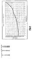
figure 4 shows a graph of force that device according to the invention applies on a pack of panels and height of said panel pack. - In the different figures, similar parts will be indicated by the same reference numbers.
- Making reference to
figures 1 and2 , thedevice 100 according to the invention comprises alower jaw 10, anupper jaw 20, a connectingrod 30, apneumatic cylinder 40, ashoe 50, acontainment casing 70 and a first, a second and a fourth pin, respectively indicated byrefernece numbers - Said
lower jaw 10 is provided, at itsend 11, a tighteningtooth 12. - Said
upper jaw 20 provides, at itsend 21, a secondtighteing tooth 22, and on its back, alinear guide 23, preferably of the THK type ("THK" stands for Toughness, High Quality). - An assembly of one or
more panels 80 can be blocked between said tighteningtooth 12 and said second tighteningtooth 22. - Said connecting
rod 30 has arms placed substantially according to an L arrangement, between which it is included an angle ofabouit 100°,and it is pivoted inend 31 with saidlower jaw 10, and inend 32 with saidpneumatic cylinder 40, in itsend 42 and with saidshoe 50, by saidfourth pin 64. - Said
pneumatic cylinder 40 can take an operative position and an extended position. It is pivoted at itsend 41 to saidlower jaw 10 andto saidcontainment casing 70 by saidthird pin 63. -
Shoe 50 is sliding coupled with saidlinear guide 23, so as to slide along saidupper jaw 20. - Said
contaiment case 70 is provided with aflange 71, to permit its coupling, e.g., to a pushing member of a cutting machine. Saidcontainment case 70 is, on one side, pivoted to saidlower jaw 10 and to saidupper jaw 20 by saidfirst pin 61. - As it can be observed, said
shoe 50, sliding along saidlinear guide 23 from position A to position B, transmits linear movement of saidpneumatic cylinder 40 to said connectingrod 30. The latter makes a rotatory movement from position C to position D, making said upper jaw rotating along the same direction. - When said
pneutmatic cylinder 40 takes the contracted operative position,lower jaw 10 andupper jaw 20 spread, while when saidactuator 40 takes the extended operative position,lower jaw 10 andupper jaw 20 approach each other. - The specific embodiment of said connecting
rod 30, with two arms angled each other of about 100°, involves positioning of upper arm of said connectingrod 30 in a position substantially parallel to saidpneumatic cylinder 40, when the latteris in an atleast partially extended operative position. This permits increasing resistance of saiddevice 100 when opening. - Further, position of said pins is preferably such that said
first pin 61, saidsecond pin 62 and saidthird pin 63 make a substantially rectangular triangle, and straight line R1 pasing between saidfirst pin 61 and saidsecond pin 62, and straight line R2 passing through saidthird pin 64 and saidfourth pin 64 are substantially parallel each other when saidactuator 40 takes said contracted operative position. - Making now reference to
figure 3 , it is observed a second embodiment ofblocking device 100, whereinshoe 50 is replaced by aroller 51, coupled with saidupper jaw 20, so as to be able rolling on the same. - Obviously, operation of blocking
device 100 according to the invention is completely similar to operation of the one shown infigures 1 and2 . - Making now reference to
figures 4 , it is possible observing test data obtained from use tests fordevice 100 according to the invention. Along abscissae there are different heights of said one ormore panel stack 80, while along ordinate it is indicated, by Newton, force exerted by saiddevice 100 on said panels in correspondence of said heights. It is clearly observed that with increase of height ofpanel stack 80 increases also force exerted onpanels 80. - Present inventio has been described for illustrative, but not limitative, purposes according to its preferred embodiments, but it is well evident that variations and/or modifications can be introduced by those skilled in the art without departing from the relevant scope, as defined in the enclosed claims.
Claims (9)
- Device (100) for blocking one or more panels (80), in particular for panel cutting machines, comprising a lower jaw (10); an upper jaw (20), pivoted to said lower jaw (10) by a first pivot (61), said one or more panels being blockable between said lower jaw (10) and said upper jaw (20); at least a connecting rod (30), having a first end (31) and a second end (32), said first end (31) being pivoted on said lower jaw (10) by a second pivot (62); and an actuator (40), preferably a pneumatic cylinder, having a first end (41) and a second end (42), said first end (41) of said actuator (40) being pivoted to a third pivot (63) on said lower jaw (10), said actuator (40) being capable of assuming a contracted operative position and an extended operative position, characterized in that said device (100) further comprises moving means (50, 51) coupled with said upper jaw (20), movable with respect the same and coupled with said connecting rod (30), and in that said actuator (40) is coupled with said connecting rod (30) to said second end (42), so that when said actuator (40) takes said contracted operative position, said lower jaw (10) and said upper jaw (20) move apart, while when said actuator (40) takes said extended operative position, said lower jaw (10) and said upper jaw (20) close each other.
- Blocking device (100) according to claim 1, characterized in that said upper jaw (20) provides a linear guide (23), preferably of the THK type, and in that said moving means is a slide (50) slidably coupled with said linear guide (23) of said upper jaw (20).
- Blocking device (100) according to claim 1, characterized in that said moving means is a wheel (51) coupled with said upper jaw (20) so as to be suitable to roll on the same.
- Blocking device (100) according to anyone of the preceding claims, characterized in that said moving means (50), said connecting rod (30) and said second end (42) of said actuator (40) are pivoted about a same fourth pivot (64) said connecting rod (30) having preferably said second end (32) pivoted about said fourth pivot (64).
- Blocking device (100) according to anyone of the preceding claims, characterized in that said first end (31) of said connecting rod (30) is pivoted on a substantially intermediate point of the longitudinal extension of said lower jaw (10).
- Blocking device (100) according to anyone of the preceding claims, characterized in that it comprises a containment casing (70) having a coupling flange (71), in particular for coupling with a member of a machine moving said containment casing.
- Blocking device (100) according to claim 6, characterized in that said lower jaw (10), said upper jaw (20) and said containment casing (70) are pivoted about said first pivot (61).
- Blocking device (100) according to anyone of the preceding claims, characterized in that said first pivot (61), said second pivot (62) and said third pivot (63) form a substantially rectangle triangle, and the straight line (R1) passing through said first pivot (61) and said second pivot (62) and the straight line (R2) passing through said third pivot (63) and said fourth pivot (64) are substantially parallel when said actuator (40) takes said contracted operative position.
- Blocking device (100) according to anyone of the preceding claims, characterized in that said lower jaw (10) is provided at one end (11) with a first tightening tooth (12), said upper jaw (20) is provided at one end (21) with a second tightening tooth (22), said one or more panels (80) being blockable between said first tightening tooth (12) and said second tightening tooth (22).
Applications Claiming Priority (1)
| Application Number | Priority Date | Filing Date | Title |
|---|---|---|---|
| ITRM2009A000404A IT1395229B1 (en) | 2009-07-30 | 2009-07-30 | LOCKING DEVICE, IN PARTICULAR FOR PANELS. |
Publications (2)
| Publication Number | Publication Date |
|---|---|
| EP2279820A1 true EP2279820A1 (en) | 2011-02-02 |
| EP2279820B1 EP2279820B1 (en) | 2012-03-21 |
Family
ID=41728129
Family Applications (1)
| Application Number | Title | Priority Date | Filing Date |
|---|---|---|---|
| EP10425239A Not-in-force EP2279820B1 (en) | 2009-07-30 | 2010-07-16 | Blocking device, particularly for panels |
Country Status (3)
| Country | Link |
|---|---|
| EP (1) | EP2279820B1 (en) |
| AT (1) | ATE550124T1 (en) |
| IT (1) | IT1395229B1 (en) |
Citations (2)
| Publication number | Priority date | Publication date | Assignee | Title |
|---|---|---|---|---|
| DE19502659A1 (en) * | 1994-03-09 | 1995-09-14 | Schelling & Co | Clamp for inserting sets for plate stack dividing installation |
| DE202007002932U1 (en) | 2007-02-28 | 2007-05-24 | Holzma Plattenaufteiltechnik Gmbh | Gripping device, especially a collect chuck, for use in a forward-feed device for plate-/panel-shaped work-pieces moves along a forward-feed direction to grip the work-piece |
-
2009
- 2009-07-30 IT ITRM2009A000404A patent/IT1395229B1/en active
-
2010
- 2010-07-16 AT AT10425239T patent/ATE550124T1/en active
- 2010-07-16 EP EP10425239A patent/EP2279820B1/en not_active Not-in-force
Patent Citations (2)
| Publication number | Priority date | Publication date | Assignee | Title |
|---|---|---|---|---|
| DE19502659A1 (en) * | 1994-03-09 | 1995-09-14 | Schelling & Co | Clamp for inserting sets for plate stack dividing installation |
| DE202007002932U1 (en) | 2007-02-28 | 2007-05-24 | Holzma Plattenaufteiltechnik Gmbh | Gripping device, especially a collect chuck, for use in a forward-feed device for plate-/panel-shaped work-pieces moves along a forward-feed direction to grip the work-piece |
Also Published As
| Publication number | Publication date |
|---|---|
| EP2279820B1 (en) | 2012-03-21 |
| ATE550124T1 (en) | 2012-04-15 |
| IT1395229B1 (en) | 2012-09-05 |
| ITRM20090404A1 (en) | 2011-01-31 |
Similar Documents
| Publication | Publication Date | Title |
|---|---|---|
| JP4979628B2 (en) | Biaxial tensile testing device | |
| EP3251797B1 (en) | Pliers | |
| KR102109732B1 (en) | band cutter device | |
| CN103537591B (en) | Angular Displacement component for stamping tool | |
| CN104043762B (en) | The transversal bar punching mechanism of reinforcing mesh welding production line | |
| EP3647004A1 (en) | Cutting machine to cut panels made of wood or the like | |
| DK2699366T3 (en) | Bending machine for bending metal rods, such as round pieces for reinforcement, etc. | |
| EP2279820B1 (en) | Blocking device, particularly for panels | |
| CN201033416Y (en) | Large vice with narrow and long lever | |
| CN101428406A (en) | Labor saving pliers | |
| SE1100285A1 (en) | Hand-operated crimping tool | |
| GB2493878A (en) | Clamp and repair tool | |
| SE536955C2 (en) | Clamping tool and method for mounting / removing a clamping jaw or support for such | |
| CN208099461U (en) | A kind of plate shearing machine convenient for adjusting sheared length | |
| CN201267999Y (en) | Labor saving wire clippers | |
| DK173182B1 (en) | Gripping means with holding jaws or gripping fingers for handling rod-shaped items. | |
| CN220499173U (en) | Glass bait grabbing device | |
| SE1100284A1 (en) | Hand-operated crimping tool | |
| EP1808268A2 (en) | Drive device for actuating a linearly movable operative member | |
| KR101641735B1 (en) | Apparatus for measuring hardness of steel sheet | |
| CN201295933Y (en) | Labor-saving clamp | |
| EP2740567A3 (en) | A device for reduction of force transfer to a frame consisting of two parts force-interacting on each other | |
| US20200130145A1 (en) | Hand tool with adjustable release function | |
| NO313542B1 (en) | Pliers for mechanical machining of workpieces | |
| CN221538537U (en) | Positioning device for blanking of laser cutting machine |
Legal Events
| Date | Code | Title | Description |
|---|---|---|---|
| PUAI | Public reference made under article 153(3) epc to a published international application that has entered the european phase |
Free format text: ORIGINAL CODE: 0009012 |
|
| AK | Designated contracting states |
Kind code of ref document: A1 Designated state(s): AL AT BE BG CH CY CZ DE DK EE ES FI FR GB GR HR HU IE IS IT LI LT LU LV MC MK MT NL NO PL PT RO SE SI SK SM TR |
|
| AX | Request for extension of the european patent |
Extension state: BA ME RS |
|
| 17P | Request for examination filed |
Effective date: 20110726 |
|
| GRAP | Despatch of communication of intention to grant a patent |
Free format text: ORIGINAL CODE: EPIDOSNIGR1 |
|
| RIC1 | Information provided on ipc code assigned before grant |
Ipc: B23D 47/04 20060101AFI20110831BHEP |
|
| GRAS | Grant fee paid |
Free format text: ORIGINAL CODE: EPIDOSNIGR3 |
|
| GRAA | (expected) grant |
Free format text: ORIGINAL CODE: 0009210 |
|
| AK | Designated contracting states |
Kind code of ref document: B1 Designated state(s): AL AT BE BG CH CY CZ DE DK EE ES FI FR GB GR HR HU IE IS IT LI LT LU LV MC MK MT NL NO PL PT RO SE SI SK SM TR |
|
| REG | Reference to a national code |
Ref country code: GB Ref legal event code: FG4D |
|
| REG | Reference to a national code |
Ref country code: CH Ref legal event code: EP |
|
| REG | Reference to a national code |
Ref country code: IE Ref legal event code: FG4D |
|
| REG | Reference to a national code |
Ref country code: AT Ref legal event code: REF Ref document number: 550124 Country of ref document: AT Kind code of ref document: T Effective date: 20120415 |
|
| REG | Reference to a national code |
Ref country code: DE Ref legal event code: R096 Ref document number: 602010001144 Country of ref document: DE Effective date: 20120516 |
|
| REG | Reference to a national code |
Ref country code: NL Ref legal event code: VDEP Effective date: 20120321 |
|
| PG25 | Lapsed in a contracting state [announced via postgrant information from national office to epo] |
Ref country code: NO Free format text: LAPSE BECAUSE OF FAILURE TO SUBMIT A TRANSLATION OF THE DESCRIPTION OR TO PAY THE FEE WITHIN THE PRESCRIBED TIME-LIMIT Effective date: 20120621 Ref country code: LT Free format text: LAPSE BECAUSE OF FAILURE TO SUBMIT A TRANSLATION OF THE DESCRIPTION OR TO PAY THE FEE WITHIN THE PRESCRIBED TIME-LIMIT Effective date: 20120321 Ref country code: HR Free format text: LAPSE BECAUSE OF FAILURE TO SUBMIT A TRANSLATION OF THE DESCRIPTION OR TO PAY THE FEE WITHIN THE PRESCRIBED TIME-LIMIT Effective date: 20120321 |
|
| LTIE | Lt: invalidation of european patent or patent extension |
Effective date: 20120321 |
|
| PG25 | Lapsed in a contracting state [announced via postgrant information from national office to epo] |
Ref country code: FI Free format text: LAPSE BECAUSE OF FAILURE TO SUBMIT A TRANSLATION OF THE DESCRIPTION OR TO PAY THE FEE WITHIN THE PRESCRIBED TIME-LIMIT Effective date: 20120321 Ref country code: GR Free format text: LAPSE BECAUSE OF FAILURE TO SUBMIT A TRANSLATION OF THE DESCRIPTION OR TO PAY THE FEE WITHIN THE PRESCRIBED TIME-LIMIT Effective date: 20120622 Ref country code: LV Free format text: LAPSE BECAUSE OF FAILURE TO SUBMIT A TRANSLATION OF THE DESCRIPTION OR TO PAY THE FEE WITHIN THE PRESCRIBED TIME-LIMIT Effective date: 20120321 |
|
| PG25 | Lapsed in a contracting state [announced via postgrant information from national office to epo] |
Ref country code: CY Free format text: LAPSE BECAUSE OF FAILURE TO SUBMIT A TRANSLATION OF THE DESCRIPTION OR TO PAY THE FEE WITHIN THE PRESCRIBED TIME-LIMIT Effective date: 20120321 |
|
| PG25 | Lapsed in a contracting state [announced via postgrant information from national office to epo] |
Ref country code: PL Free format text: LAPSE BECAUSE OF FAILURE TO SUBMIT A TRANSLATION OF THE DESCRIPTION OR TO PAY THE FEE WITHIN THE PRESCRIBED TIME-LIMIT Effective date: 20120321 Ref country code: IS Free format text: LAPSE BECAUSE OF FAILURE TO SUBMIT A TRANSLATION OF THE DESCRIPTION OR TO PAY THE FEE WITHIN THE PRESCRIBED TIME-LIMIT Effective date: 20120721 Ref country code: EE Free format text: LAPSE BECAUSE OF FAILURE TO SUBMIT A TRANSLATION OF THE DESCRIPTION OR TO PAY THE FEE WITHIN THE PRESCRIBED TIME-LIMIT Effective date: 20120321 Ref country code: CZ Free format text: LAPSE BECAUSE OF FAILURE TO SUBMIT A TRANSLATION OF THE DESCRIPTION OR TO PAY THE FEE WITHIN THE PRESCRIBED TIME-LIMIT Effective date: 20120321 Ref country code: RO Free format text: LAPSE BECAUSE OF FAILURE TO SUBMIT A TRANSLATION OF THE DESCRIPTION OR TO PAY THE FEE WITHIN THE PRESCRIBED TIME-LIMIT Effective date: 20120321 Ref country code: BE Free format text: LAPSE BECAUSE OF FAILURE TO SUBMIT A TRANSLATION OF THE DESCRIPTION OR TO PAY THE FEE WITHIN THE PRESCRIBED TIME-LIMIT Effective date: 20120321 Ref country code: SE Free format text: LAPSE BECAUSE OF FAILURE TO SUBMIT A TRANSLATION OF THE DESCRIPTION OR TO PAY THE FEE WITHIN THE PRESCRIBED TIME-LIMIT Effective date: 20120321 Ref country code: SI Free format text: LAPSE BECAUSE OF FAILURE TO SUBMIT A TRANSLATION OF THE DESCRIPTION OR TO PAY THE FEE WITHIN THE PRESCRIBED TIME-LIMIT Effective date: 20120321 |
|
| PG25 | Lapsed in a contracting state [announced via postgrant information from national office to epo] |
Ref country code: SK Free format text: LAPSE BECAUSE OF FAILURE TO SUBMIT A TRANSLATION OF THE DESCRIPTION OR TO PAY THE FEE WITHIN THE PRESCRIBED TIME-LIMIT Effective date: 20120321 Ref country code: PT Free format text: LAPSE BECAUSE OF FAILURE TO SUBMIT A TRANSLATION OF THE DESCRIPTION OR TO PAY THE FEE WITHIN THE PRESCRIBED TIME-LIMIT Effective date: 20120723 |
|
| PLBE | No opposition filed within time limit |
Free format text: ORIGINAL CODE: 0009261 |
|
| STAA | Information on the status of an ep patent application or granted ep patent |
Free format text: STATUS: NO OPPOSITION FILED WITHIN TIME LIMIT |
|
| PG25 | Lapsed in a contracting state [announced via postgrant information from national office to epo] |
Ref country code: NL Free format text: LAPSE BECAUSE OF FAILURE TO SUBMIT A TRANSLATION OF THE DESCRIPTION OR TO PAY THE FEE WITHIN THE PRESCRIBED TIME-LIMIT Effective date: 20120321 Ref country code: DK Free format text: LAPSE BECAUSE OF FAILURE TO SUBMIT A TRANSLATION OF THE DESCRIPTION OR TO PAY THE FEE WITHIN THE PRESCRIBED TIME-LIMIT Effective date: 20120321 |
|
| 26N | No opposition filed |
Effective date: 20130102 |
|
| PG25 | Lapsed in a contracting state [announced via postgrant information from national office to epo] |
Ref country code: MC Free format text: LAPSE BECAUSE OF NON-PAYMENT OF DUE FEES Effective date: 20120731 Ref country code: MK Free format text: LAPSE BECAUSE OF FAILURE TO SUBMIT A TRANSLATION OF THE DESCRIPTION OR TO PAY THE FEE WITHIN THE PRESCRIBED TIME-LIMIT Effective date: 20120321 |
|
| REG | Reference to a national code |
Ref country code: DE Ref legal event code: R097 Ref document number: 602010001144 Country of ref document: DE Effective date: 20130102 |
|
| REG | Reference to a national code |
Ref country code: FR Ref legal event code: ST Effective date: 20130329 |
|
| PG25 | Lapsed in a contracting state [announced via postgrant information from national office to epo] |
Ref country code: FR Free format text: LAPSE BECAUSE OF NON-PAYMENT OF DUE FEES Effective date: 20120731 Ref country code: ES Free format text: LAPSE BECAUSE OF FAILURE TO SUBMIT A TRANSLATION OF THE DESCRIPTION OR TO PAY THE FEE WITHIN THE PRESCRIBED TIME-LIMIT Effective date: 20120702 |
|
| REG | Reference to a national code |
Ref country code: IE Ref legal event code: MM4A |
|
| PG25 | Lapsed in a contracting state [announced via postgrant information from national office to epo] |
Ref country code: IE Free format text: LAPSE BECAUSE OF NON-PAYMENT OF DUE FEES Effective date: 20120716 Ref country code: BG Free format text: LAPSE BECAUSE OF FAILURE TO SUBMIT A TRANSLATION OF THE DESCRIPTION OR TO PAY THE FEE WITHIN THE PRESCRIBED TIME-LIMIT Effective date: 20120621 Ref country code: MT Free format text: LAPSE BECAUSE OF FAILURE TO SUBMIT A TRANSLATION OF THE DESCRIPTION OR TO PAY THE FEE WITHIN THE PRESCRIBED TIME-LIMIT Effective date: 20120321 |
|
| PG25 | Lapsed in a contracting state [announced via postgrant information from national office to epo] |
Ref country code: AL Free format text: LAPSE BECAUSE OF FAILURE TO SUBMIT A TRANSLATION OF THE DESCRIPTION OR TO PAY THE FEE WITHIN THE PRESCRIBED TIME-LIMIT Effective date: 20120321 |
|
| PG25 | Lapsed in a contracting state [announced via postgrant information from national office to epo] |
Ref country code: TR Free format text: LAPSE BECAUSE OF FAILURE TO SUBMIT A TRANSLATION OF THE DESCRIPTION OR TO PAY THE FEE WITHIN THE PRESCRIBED TIME-LIMIT Effective date: 20120321 |
|
| PG25 | Lapsed in a contracting state [announced via postgrant information from national office to epo] |
Ref country code: LU Free format text: LAPSE BECAUSE OF NON-PAYMENT OF DUE FEES Effective date: 20120716 Ref country code: SM Free format text: LAPSE BECAUSE OF FAILURE TO SUBMIT A TRANSLATION OF THE DESCRIPTION OR TO PAY THE FEE WITHIN THE PRESCRIBED TIME-LIMIT Effective date: 20120321 |
|
| PG25 | Lapsed in a contracting state [announced via postgrant information from national office to epo] |
Ref country code: HU Free format text: LAPSE BECAUSE OF FAILURE TO SUBMIT A TRANSLATION OF THE DESCRIPTION OR TO PAY THE FEE WITHIN THE PRESCRIBED TIME-LIMIT Effective date: 20100716 |
|
| REG | Reference to a national code |
Ref country code: CH Ref legal event code: PL |
|
| GBPC | Gb: european patent ceased through non-payment of renewal fee |
Effective date: 20140716 |
|
| PG25 | Lapsed in a contracting state [announced via postgrant information from national office to epo] |
Ref country code: CH Free format text: LAPSE BECAUSE OF NON-PAYMENT OF DUE FEES Effective date: 20140731 Ref country code: LI Free format text: LAPSE BECAUSE OF NON-PAYMENT OF DUE FEES Effective date: 20140731 |
|
| PG25 | Lapsed in a contracting state [announced via postgrant information from national office to epo] |
Ref country code: GB Free format text: LAPSE BECAUSE OF NON-PAYMENT OF DUE FEES Effective date: 20140716 |
|
| PGFP | Annual fee paid to national office [announced via postgrant information from national office to epo] |
Ref country code: DE Payment date: 20180725 Year of fee payment: 9 Ref country code: IT Payment date: 20180710 Year of fee payment: 9 |
|
| PGFP | Annual fee paid to national office [announced via postgrant information from national office to epo] |
Ref country code: AT Payment date: 20180719 Year of fee payment: 9 |
|
| REG | Reference to a national code |
Ref country code: DE Ref legal event code: R119 Ref document number: 602010001144 Country of ref document: DE |
|
| REG | Reference to a national code |
Ref country code: AT Ref legal event code: MM01 Ref document number: 550124 Country of ref document: AT Kind code of ref document: T Effective date: 20190716 |
|
| PG25 | Lapsed in a contracting state [announced via postgrant information from national office to epo] |
Ref country code: AT Free format text: LAPSE BECAUSE OF NON-PAYMENT OF DUE FEES Effective date: 20190716 Ref country code: DE Free format text: LAPSE BECAUSE OF NON-PAYMENT OF DUE FEES Effective date: 20200201 |
|
| PG25 | Lapsed in a contracting state [announced via postgrant information from national office to epo] |
Ref country code: IT Free format text: LAPSE BECAUSE OF NON-PAYMENT OF DUE FEES Effective date: 20190716 |