EP2279655A1 - Positive open grain saving unloading system - Google Patents
Positive open grain saving unloading system Download PDFInfo
- Publication number
- EP2279655A1 EP2279655A1 EP10171487A EP10171487A EP2279655A1 EP 2279655 A1 EP2279655 A1 EP 2279655A1 EP 10171487 A EP10171487 A EP 10171487A EP 10171487 A EP10171487 A EP 10171487A EP 2279655 A1 EP2279655 A1 EP 2279655A1
- Authority
- EP
- European Patent Office
- Prior art keywords
- door
- grain
- open position
- fully open
- unloading
- Prior art date
- Legal status (The legal status is an assumption and is not a legal conclusion. Google has not performed a legal analysis and makes no representation as to the accuracy of the status listed.)
- Granted
Links
Images




Classifications
-
- B—PERFORMING OPERATIONS; TRANSPORTING
- B65—CONVEYING; PACKING; STORING; HANDLING THIN OR FILAMENTARY MATERIAL
- B65G—TRANSPORT OR STORAGE DEVICES, e.g. CONVEYORS FOR LOADING OR TIPPING, SHOP CONVEYOR SYSTEMS OR PNEUMATIC TUBE CONVEYORS
- B65G33/00—Screw or rotary spiral conveyors
- B65G33/08—Screw or rotary spiral conveyors for fluent solid materials
- B65G33/14—Screw or rotary spiral conveyors for fluent solid materials comprising a screw or screws enclosed in a tubular housing
- B65G33/22—Screw or rotary spiral conveyors for fluent solid materials comprising a screw or screws enclosed in a tubular housing with means for retarding material flow at the delivery end of the housing
-
- A—HUMAN NECESSITIES
- A01—AGRICULTURE; FORESTRY; ANIMAL HUSBANDRY; HUNTING; TRAPPING; FISHING
- A01D—HARVESTING; MOWING
- A01D41/00—Combines, i.e. harvesters or mowers combined with threshing devices
- A01D41/12—Details of combines
- A01D41/1208—Tanks for grain or chaff
- A01D41/1217—Unloading mechanisms
Definitions
- the present invention relates to an unloading system for an agricultural harvesting machine, and more particularly, to a grain saving unloading system for reducing grain loss, by detaining a grain saver door after movement to a fully open position, allowing unopposed flow of grain during the unloading process, and by rapidly returning the door to a closed position with sufficient force for urging grain in the door area back into the tube a predetermined time after the unloading process pauses or ceases.
- Unloading of grain from harvesters such as combines is typically accomplished using an elongate unloading tube including a helical auger contained therein.
- the unloading tube has a discharge opening through which grain is propelled by rotation of the auger.
- grain is moved from a grain tank of the harvester to another tank or receptacle, such as on a truck or wagon.
- a well-known problem associated with unloading systems of combine harvesters is that grain remaining in the unloading tube at the end of the unloading process can continue to dribble out of the discharge opening as the unloading tube is swung to its transport position.
- grain has been observed to dribble out of the discharge opening with the unloading tube in the transport position, particularly as the harvester is moved over rough terrain, up hills, and the like.
- dribble doors A variety of doors referred to as dribble doors, spill saver doors, or grain saver doors have been utilized in attempts to reduce the dribble problem.
- dribble doors Usually these doors are biased, typically by a spring, to a closed position in covering relation to at least a portion of the discharge opening.
- the auger rotates, grain is moved through the unloading tube to the discharge opening exerting a force against the door.
- the spring yields allowing the door to open and the grain to discharge.
- the operator of the receiving vehicle may attempt to position one side or the other of the receiving vehicle more beneath the spout such that, with wind drift, the stream of grain will be directed more to the center of the receiving vehicle. This is facilitated by a tighter, more cohesive flow of discharging grain.
- US-A-2008/0149463 proposes to remove the spring and to connect an actuator to the door for positively controlling the position of the door.
- the good operation of the actuator is critical to the overall harvesting operations, as a failure or a late actuation to open the door will inhibit the unloading operation and leave the operator stranded with a full grain tank.
- the grain unloading system includes an unloading tube defining an internal passage in connection with a discharge opening at an end of the tube.
- the tube contains an auger rotatable for conveying grain through the internal passage of the tube and discharging the grain through the discharge opening along a flow path.
- the invention includes a grain saver door pivotally mounted in connection with the unloading tube adjacent to the discharge opening. The door is supported for pivotal movement along a path between a closed position in covering relation to at least a lower region of the discharge opening through a range of partially open positions and a fully open position.
- a biasing element is disposed and configured in connection with the door, urging the door toward the closed position.
- the biasing element is further configured to be yieldable to a force exerted thereagainst by the door as a result of the rotation of the auger forcing the discharging grain against the door so as to allow the door to be movable, by the force, from the closed position through the range of partially open positions to the fully open position.
- a detent device is disposed and cooperatively configured with the biasing element for detaining the door when moved to the fully open position and subsequently when the force exerted by the door ceases.
- the detent device is further cooperatively configured with the biasing element such that when the detent device releases the door from the fully open position in a predetermined manner and the force exerted as a result of the discharging grain against the door is absent, the biasing element will urge the door toward the closed position with sufficient force to propel any grain along the path of the door or in the discharge opening into the unloading tube.
- This feature further prevents grain spillage because grain that would normally remain near the discharge opening is propelled further back into the tube. If the door were to open inadvertently, little or no grain is present at the opening to spill.
- the door is attached to the unloading tube at a location below the flow path such that the door, in the fully open position, will be located beneath the flow path to allow the discharging of the grain thereover unopposed by the door.
- the detent device can be configured to be manually operable so an operator of the machine or wagon can release the door from the fully open position.
- the detent device can be configured to be automatically operable to release the door from the fully open position a predetermined length of time after cessation of rotation of the auger, such as when the unloading process is paused or completed. This results in the door remaining open to allow additional grain in the path of the door or in the discharge opening to fall away from the unloading tube. After this delay, the door is released from the fully open position propelling grain in the door area into the unloading tube.
- the detent device includes an element disposed in the path of the door proximate the fully open position.
- the element is biased for yielding to the door when moving along the path toward the fully open position, and then being operable to return to the path for detaining the door in the fully open position thereafter.
- the detent device further includes a controllably operable device operable for removing the element from the path of the door for releasing the door from the fully open position.
- Preferred apparatus of the system include, but are not limited to, a latching device controlled by a solenoid, fluid controlled actuators and electrically powered actuators.
- FIG. 1 a representative agricultural harvesting machine 10, which is a combine harvester of well-known construction and operation, is shown, including an unloading system 20 constructed and operable according to the teachings of the present invention.
- a cylindrical shaped unloading tube 12 is shown in a sidewardly and upwardly extending deployed or unloading position, for unloading grain into an accompanying container, which here is illustrated by a conventional agricultural grain wagon 14, in the well known manner.
- This is intended to be representative of a wide variety of unloading operations, wherein the flow of grain 16 from machine 10 is to be directed into a receiving container, such as wagon 14, periodically during operation of machine 10.
- unloading tube 12 is stored in a position extending rearwardly (not shown) from machine 10, also in the well known manner.
- Unloading tube 12 defines an internal passage containing a helical auger rotatable for conveying grain through the internal passage of tube 12 and discharging the grain through a discharge opening 18 and a discharge spout 16 along a flow path as shown in Figure 1 .
- Grain unloading systems may include a grain saver door 22 pivotally mounted in connection with unloading tube 12 adjacent to discharge opening 18 as can be seen in Figures 2-6 .
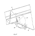
- Door 22 is supported for pivotal movement along a path between a closed position in covering relation to at least a lower region of discharge opening 18 as seen in Figures 2 and 3 through a range of partially open positions depicted by arrow 24 in Figure 4 and a fully open position as seen in Figures 5 and 6 .
- a biasing element 26, shown here as a spring, is disposed and configured in connection with door 22, urging door 22 toward the closed position.
- Biasing element 26 is further configured so as to be yieldable to a force exerted thereagainst by door 22 as a result of the rotation of the auger forcing the discharging grain against door 22 so as to allow door 22 to be movable, by the force, from the closed position through the range of partially open positions to the fully open position.
- the biasing force urging door 22 to the closed position can interfere with the flow of grain when smaller or irregular amounts of grain are present making the flow susceptible to redirection by wind drift as discussed above. As the discharging grain flow tapers off, the biasing force can prematurely close door 22 so as to trap an undesirable amount of grain near discharge opening 18 of unloading tube 12 creating a risk of loss due to spillage or dribble.
- An unloading system 20 of the present invention improves the cohesiveness and consistency of the flow of grain by providing a detent device 28 disposed and cooperatively configured with biasing element 26 for detaining door 22 when moved to the fully open position and subsequently when the force exerted by door 22 ceases.
- the flow of grain is not affected by a varying door position so even when only small amounts of grain are being discharged, such as when the grain tank is nearly empty.
- the smaller or irregular amounts of grain are discharged without the need to exert force against door 22 just to maintain door 22 in the open position.
- the grain is allowed to flow unopposed, as if no door was present, such that it is discharged in a more cohesive, predictable flow of grain.
- Detent device 28 is further cooperatively configured with biasing element 26 such that when detent device 28 releases door 22 from the fully open position in a predetermined manner and the force exerted as a result of the discharging grain against door 22 is absent, biasing element 26 will urge door 22 toward the closed position with sufficient force to propel any grain along the path of door 22 or in discharge opening 18 into unloading tube 12.
- biasing element 26 will urge door 22 toward the closed position with sufficient force to propel any grain along the path of door 22 or in discharge opening 18 into unloading tube 12.
- the amount of grain remaining at discharge opening 18 is reduced as illustrated in Figure 7 . Even if door 22 were to open inadvertently, such as when machine 10 moves over rugged or hilly terrain, less grain is present at opening 18 to dribble or spill.
- Door 22 is preferably attached to unloading tube 12 at a location below the flow path such that door 22, in the fully open position, will be located beneath the flow path to allow the discharging of the grain thereover unopposed by door 22 to further ensure a cohesive flow of discharging grain as if not door were present.
- Detent device 28 can be configured to be manually operable so an operator of machine 10 or wagon 14 can release door 22 from the fully open position. Alternately, detent device 28 can be configured to be automatically operable to release door 22 from the fully open position a predetermined length of time after cessation of rotation of the auger, such as when the unloading process is paused or completed.
- Figure 11 includes a flow diagram of the automatic process. At block 50, the unloading process begins and the rotation of the auger moves grain toward discharge opening 18 through unloading tube 12. The discharging grain urges door 20 from its closed position to the fully open position as seen at block 52. Unloading system 20 operates to detain door 20 in the fully open position as shown in block 54.
- unloading system 20 waits a predetermined time before releasing door 22 from the fully open position as seen in blocks 56, 58, 60. During this delay, additional grain in the path of door 22 or in discharge opening 18 is allowed to fall from unloading tube 12 before door 22 is released propelling remaining grain in the door area into unloading tube 22.
- detent device 28 includes an element 30 disposed in the path of door 22 proximate the fully open position.
- Element 30 is biased for yielding to door 22 when moving along the path toward the fully open position and operable to return to the path for detaining door 22 in the fully open position thereafter.
- a schematic of a representative detent device is shown in Figure 8 in which element 30 is biased, such as by a spring 32, for yielding to door 22 when moving along the path toward the fully open position.
- element 30 When opening, door 22 exerts a force represented by arrow 36 on a surface 34 of element 30.
- Spring 32 yields to force 36 and element 30 pivots in the direction of arrow 38 allowing door 22 to reach the fully open position.
- Detent device 28 further includes a controllably operable device 40 operable for removing element 30 from the path of door 22 for releasing door 22 from the fully open position.
- Electromagnet 46 detains door 22 in the fully open position. Electromagnet 46 can be manually or automatically operable to release door 22 from the fully open position to the closed position.
- detent device 28 Yet another embodiment of detent device 28 is shown in Figure 10 . Once door 22 has moved to the fully open position, element 44 of detent device 28 extends from the side into the path of door 22 detaining it in the fully open position, until solenoid 42 is activated (either manually or automatically) to release door 22 from the fully open position.
Landscapes
- Engineering & Computer Science (AREA)
- Mechanical Engineering (AREA)
- Life Sciences & Earth Sciences (AREA)
- Environmental Sciences (AREA)
- Threshing Machine Elements (AREA)
Abstract
Description
- The present invention relates to an unloading system for an agricultural harvesting machine, and more particularly, to a grain saving unloading system for reducing grain loss, by detaining a grain saver door after movement to a fully open position, allowing unopposed flow of grain during the unloading process, and by rapidly returning the door to a closed position with sufficient force for urging grain in the door area back into the tube a predetermined time after the unloading process pauses or ceases.
- Unloading of grain from harvesters such as combines, is typically accomplished using an elongate unloading tube including a helical auger contained therein. The unloading tube has a discharge opening through which grain is propelled by rotation of the auger. During an unloading process of the combine, grain is moved from a grain tank of the harvester to another tank or receptacle, such as on a truck or wagon.
- A well-known problem associated with unloading systems of combine harvesters is that grain remaining in the unloading tube at the end of the unloading process can continue to dribble out of the discharge opening as the unloading tube is swung to its transport position. In addition, grain has been observed to dribble out of the discharge opening with the unloading tube in the transport position, particularly as the harvester is moved over rough terrain, up hills, and the like.
- A variety of doors referred to as dribble doors, spill saver doors, or grain saver doors have been utilized in attempts to reduce the dribble problem. Usually these doors are biased, typically by a spring, to a closed position in covering relation to at least a portion of the discharge opening. As the auger rotates, grain is moved through the unloading tube to the discharge opening exerting a force against the door. As the force of the discharging grain increases, the spring yields allowing the door to open and the grain to discharge.
- An observed shortcoming of these doors is that the biasing forces urging the door to the closed position tend to interfere with the flow of grain, especially when smaller or irregular amounts of grain are present. The force exerted against the door by the smaller or irregular amounts of grain may only be sufficient to partially open the door or to open the door by varying amounts as the amount of grain varies. The resulting flow of grain discharged may be irregular and/or varied, as influenced by the quantity of grain present, making it susceptible to redirection by wind drift. Even a small amount of wind drift can be significant because the grain is often unloaded while the combine is moving and the receiving vehicle is being driven or towed in parallel with the combine over rough terrain or furrows making steering difficult. Often the operator of the receiving vehicle may attempt to position one side or the other of the receiving vehicle more beneath the spout such that, with wind drift, the stream of grain will be directed more to the center of the receiving vehicle. This is facilitated by a tighter, more cohesive flow of discharging grain.
- A variety of doors have been utilized in attempts to address these shortcomings. Reference in this regard
US-B-6691861 , which discloses a dribble door pivotally mounted to a bottom periphery of an unloading tube, for preventing dribble when in a raised position, and which has a spout like shape to allow unobstructed grain flow when in a lowered position. However, a spring biases the door toward the raised position requiring the force exerted by the grain to maintain the door in the lowered position. As the discharging grain flow tapers off, the spring force can prematurely lift the door so as to trap an undesirable amount of grain at the discharge opening of the unloading tube. And, if a large quantity of grain remains, and the spring force is low or weak, the door can be opened by jarring and the like, so as to dribble grain. -
US-A-2008/0149463 proposes to remove the spring and to connect an actuator to the door for positively controlling the position of the door. The good operation of the actuator is critical to the overall harvesting operations, as a failure or a late actuation to open the door will inhibit the unloading operation and leave the operator stranded with a full grain tank. - Thus, what is sought is a grain unloading system which provides one or more of the capabilities, and overcomes one or more of the shortcomings and limitations, set forth above.
- According to the present invention, what is provided is a grain unloading system which provides one or more of the capabilities, and overcomes one or more of the shortcomings and limitations, set forth above.
- According to one preferred aspect of the invention, the grain unloading system includes an unloading tube defining an internal passage in connection with a discharge opening at an end of the tube. The tube contains an auger rotatable for conveying grain through the internal passage of the tube and discharging the grain through the discharge opening along a flow path. The invention includes a grain saver door pivotally mounted in connection with the unloading tube adjacent to the discharge opening. The door is supported for pivotal movement along a path between a closed position in covering relation to at least a lower region of the discharge opening through a range of partially open positions and a fully open position. A biasing element is disposed and configured in connection with the door, urging the door toward the closed position. The biasing element is further configured to be yieldable to a force exerted thereagainst by the door as a result of the rotation of the auger forcing the discharging grain against the door so as to allow the door to be movable, by the force, from the closed position through the range of partially open positions to the fully open position. A detent device is disposed and cooperatively configured with the biasing element for detaining the door when moved to the fully open position and subsequently when the force exerted by the door ceases.
- According to another aspect of the invention, the detent device is further cooperatively configured with the biasing element such that when the detent device releases the door from the fully open position in a predetermined manner and the force exerted as a result of the discharging grain against the door is absent, the biasing element will urge the door toward the closed position with sufficient force to propel any grain along the path of the door or in the discharge opening into the unloading tube. This feature further prevents grain spillage because grain that would normally remain near the discharge opening is propelled further back into the tube. If the door were to open inadvertently, little or no grain is present at the opening to spill.
- According to a feature of the invention, the door is attached to the unloading tube at a location below the flow path such that the door, in the fully open position, will be located beneath the flow path to allow the discharging of the grain thereover unopposed by the door.
- According to additional features of the invention, the detent device can be configured to be manually operable so an operator of the machine or wagon can release the door from the fully open position. Alternately, the detent device can be configured to be automatically operable to release the door from the fully open position a predetermined length of time after cessation of rotation of the auger, such as when the unloading process is paused or completed. This results in the door remaining open to allow additional grain in the path of the door or in the discharge opening to fall away from the unloading tube. After this delay, the door is released from the fully open position propelling grain in the door area into the unloading tube.
- According to another feature of the invention, the detent device includes an element disposed in the path of the door proximate the fully open position. The element is biased for yielding to the door when moving along the path toward the fully open position, and then being operable to return to the path for detaining the door in the fully open position thereafter. The detent device further includes a controllably operable device operable for removing the element from the path of the door for releasing the door from the fully open position.
- Preferred apparatus of the system include, but are not limited to, a latching device controlled by a solenoid, fluid controlled actuators and electrically powered actuators.
- The invention is described in further detail, by way of example only, with reference to the accompanying drawings, in which:
-
Figure 1 is a simplified front view of a combine unloading grain into a receptacle; -
Figure 2 is a partial view illustrating a discharge end of an unloading tube of the combine ofFigure 1 including a grain unloading system according to the present invention depicting a grain saver door in a closed position; -
Figure 3 is an enlarged partial cross sectional view of the unloading system ofFigure 2 depicting the grain saver door in the closed position; -
Figure 4 is an enlarged partial cross sectional view illustrating the discharge end of the unloading tube of the combine ofFigure 1 including the grain unloading system of the present invention depicting a path of partially open positions of the grain saver door; -
Figure 5 is a partial view illustrating a discharge end of the unloading tube of the combine ofFigure 1 including a grain unloading system according to present invention depicting the grain saver door in a fully open position; -
Figure 6 is an enlarged partial cross sectional view of the unloading system ofFigure 5 depicting the grain saver door in the fully open position; -
Figure 7 is a cross sectional view of the unloading system illustrating operation of the unloading system during a pause in the unloading process illustrating grain remaining in the unloading tube; -
Figure 8 is a schematic representation of a preferred embodiment of a detent device according to the present invention; -
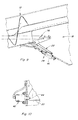
Figure 9 is an enlarged partial cross sectional view of the unloading system illustrating an alternate embodiment of a detent device according to the present invention; -
Figure 10 is an enlarged partial cross sectional view of an another embodiment of a detent device according to the present invention; and -
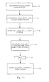
Figure 11 is a flow diagram illustration an automatic operation of the grains unloading system of the present invention. - Referring now to
Figure 1 , a representativeagricultural harvesting machine 10, which is a combine harvester of well-known construction and operation, is shown, including anunloading system 20 constructed and operable according to the teachings of the present invention. InFigure 1 , a cylindricalshaped unloading tube 12 is shown in a sidewardly and upwardly extending deployed or unloading position, for unloading grain into an accompanying container, which here is illustrated by a conventionalagricultural grain wagon 14, in the well known manner. This is intended to be representative of a wide variety of unloading operations, wherein the flow ofgrain 16 frommachine 10 is to be directed into a receiving container, such aswagon 14, periodically during operation ofmachine 10. When not in use, unloadingtube 12 is stored in a position extending rearwardly (not shown) frommachine 10, also in the well known manner. - Unloading
tube 12 defines an internal passage containing a helical auger rotatable for conveying grain through the internal passage oftube 12 and discharging the grain through adischarge opening 18 and adischarge spout 16 along a flow path as shown inFigure 1 . Grain unloading systems may include agrain saver door 22 pivotally mounted in connection with unloadingtube 12 adjacent to discharge opening 18 as can be seen inFigures 2-6 .Door 22 is supported for pivotal movement along a path between a closed position in covering relation to at least a lower region of discharge opening 18 as seen inFigures 2 and3 through a range of partially open positions depicted byarrow 24 inFigure 4 and a fully open position as seen inFigures 5 and6 . A biasingelement 26, shown here as a spring, is disposed and configured in connection withdoor 22, urgingdoor 22 toward the closed position. Biasingelement 26 is further configured so as to be yieldable to a force exerted thereagainst bydoor 22 as a result of the rotation of the auger forcing the discharging grain againstdoor 22 so as to allowdoor 22 to be movable, by the force, from the closed position through the range of partially open positions to the fully open position. - As is well known, the biasing
force urging door 22 to the closed position can interfere with the flow of grain when smaller or irregular amounts of grain are present making the flow susceptible to redirection by wind drift as discussed above. As the discharging grain flow tapers off, the biasing force can prematurely closedoor 22 so as to trap an undesirable amount of grain near discharge opening 18 of unloadingtube 12 creating a risk of loss due to spillage or dribble. - An
unloading system 20 of the present invention improves the cohesiveness and consistency of the flow of grain by providing adetent device 28 disposed and cooperatively configured with biasingelement 26 for detainingdoor 22 when moved to the fully open position and subsequently when the force exerted bydoor 22 ceases. As an advantage, the flow of grain is not affected by a varying door position so even when only small amounts of grain are being discharged, such as when the grain tank is nearly empty. The smaller or irregular amounts of grain are discharged without the need to exert force againstdoor 22 just to maintaindoor 22 in the open position. As a result, the grain is allowed to flow unopposed, as if no door was present, such that it is discharged in a more cohesive, predictable flow of grain. -
Detent device 28 is further cooperatively configured with biasingelement 26 such that whendetent device 28releases door 22 from the fully open position in a predetermined manner and the force exerted as a result of the discharging grain againstdoor 22 is absent, biasingelement 26 will urgedoor 22 toward the closed position with sufficient force to propel any grain along the path ofdoor 22 or indischarge opening 18 into unloadingtube 12. Advantageously, as the grain is propelled intotube 12, the amount of grain remaining atdischarge opening 18 is reduced as illustrated inFigure 7 . Even ifdoor 22 were to open inadvertently, such as whenmachine 10 moves over rugged or hilly terrain, less grain is present at opening 18 to dribble or spill. -
Door 22 is preferably attached to unloadingtube 12 at a location below the flow path such thatdoor 22, in the fully open position, will be located beneath the flow path to allow the discharging of the grain thereover unopposed bydoor 22 to further ensure a cohesive flow of discharging grain as if not door were present. -
Detent device 28 can be configured to be manually operable so an operator ofmachine 10 orwagon 14 can releasedoor 22 from the fully open position. Alternately,detent device 28 can be configured to be automatically operable to releasedoor 22 from the fully open position a predetermined length of time after cessation of rotation of the auger, such as when the unloading process is paused or completed.Figure 11 includes a flow diagram of the automatic process. Atblock 50, the unloading process begins and the rotation of the auger moves grain toward discharge opening 18 through unloadingtube 12. The discharging grain urgesdoor 20 from its closed position to the fully open position as seen atblock 52. Unloadingsystem 20 operates to detaindoor 20 in the fully open position as shown inblock 54. When the auger stops rotating, indicating a pause or completion of the unloading process, unloadingsystem 20 waits a predetermined time before releasingdoor 22 from the fully open position as seen inblocks door 22 or indischarge opening 18 is allowed to fall from unloadingtube 12 beforedoor 22 is released propelling remaining grain in the door area into unloadingtube 22. - As illustrated in
Figures 2-7 ,detent device 28 includes anelement 30 disposed in the path ofdoor 22 proximate the fully open position.Element 30 is biased for yielding to door 22 when moving along the path toward the fully open position and operable to return to the path for detainingdoor 22 in the fully open position thereafter. A schematic of a representative detent device is shown inFigure 8 in whichelement 30 is biased, such as by aspring 32, for yielding to door 22 when moving along the path toward the fully open position. When opening,door 22 exerts a force represented byarrow 36 on asurface 34 ofelement 30.Spring 32 yields to force 36 andelement 30 pivots in the direction ofarrow 38 allowingdoor 22 to reach the fully open position. Oncedoor 22 is in the fully open position,spring 32 urgeselement 30 to its position in the path ofdoor 22 for detainingdoor 22 in the fully open position thereafter.Detent device 28 further includes a controllablyoperable device 40 operable for removingelement 30 from the path ofdoor 22 for releasingdoor 22 from the fully open position. - Turning now to
Figure 9 wherein an alternate embodiment ofdetent device 28 is depicted. Oncedoor 22 reaches the fully open position, anelectromagnet 46 detainsdoor 22 in the fully open position.Electromagnet 46 can be manually or automatically operable to releasedoor 22 from the fully open position to the closed position. - Yet another embodiment of
detent device 28 is shown inFigure 10 . Oncedoor 22 has moved to the fully open position,element 44 ofdetent device 28 extends from the side into the path ofdoor 22 detaining it in the fully open position, untilsolenoid 42 is activated (either manually or automatically) to releasedoor 22 from the fully open position. - It will be understood that changes in the details, materials, steps, and arrangements of parts which have been described and illustrated to explain the invention will occur to and may be made by those skilled in the art upon a reading of this disclosure within the principles and scope of the invention as defined by the following claims. The foregoing description illustrates the preferred embodiment of the invention; however, concepts, as based upon the description, may be employed in other embodiments without departing from this scope of the invention.
Claims (8)
- A grain unloading system (20) for an agricultural combine (10), comprising:an unloading tube (12) defining an internal passage in connection with a discharge opening (18) at an end of the tube, the tube containing an auger rotatable for conveying grain through the internal passage of the tube (12) and discharging the grain through the discharge opening (18) along a flow path;a grain saver door (22) pivotally mounted in connection with the unloading tube (12) adjacent to the discharge opening (18), the door being supported for pivotal movement along a path (24) between a closed position in covering relation to at least a lower region of the discharge opening (18) through a range (24) of partially open positions and a fully open position for allowing discharging of grain from the opening (18); anda biasing element (26) disposed and configured in connection with the door (22), urging the door toward the closed position, the biasing element being further configured so as to be yieldable to a force (36) exerted thereagainst by the door as a result of the rotation of the auger forcing the discharging grain against the door so as to allow the door (22) to be movable by the force from the closed position through the range (24) of partially open positions to the fully open position,characterised in that it further comprises:a detent device (28) disposed and cooperatively configured with the biasing element (26) for detaining the door (22) when moved to the fully open position and subsequently when the force exerted by the door ceases.
- A grain unloading system according to claim 1, wherein the detent device (28) is further cooperatively configured with the biasing element (26) such that when the detent device releases the door (22) from the fully open position in a predetermined manner and the force exerted as a result of the discharging grain against the door is absent, the biasing element (26) will urge the door (22) toward the closed position with a sufficient force to propel any grain along the path of the door or in the discharge opening (18) into the unloading tube (12).
- A grain unloading system according to claim 1 or 2, wherein the door (22) is attached to the unloading tube (12) at a location below the flow path such that the door (22) in the fully open position will be located beneath the flow path to allow the discharging of the grain thereover essentially unopposed by the door.
- A grain unloading system according to any of the preceding claims, wherein the detent device (28) is configured to be operable by an operator to release the door (22) from the fully open position.
- A grain unloading system according to any of the preceding claims, wherein the detent device (28) is configured to be automatically operable to release the door (22) from the fully open position a predetermined length of time after cessation of rotation of the auger.
- A grain unloading system according to any of the preceding claims, wherein the detent device (28) includes an element (30) disposed in the path of the door (22) proximate the fully open position, the element being biased for yielding to the door when moving along the path toward the fully open position, and the element (30) being operable to return to the path for detaining the door (22) in the fully open position thereafter, the detent device (28) further including a controllably operable device (40) operable for removing the element (30) from the path of the door (22) for releasing the door from the fully open position.
- A grain unloading system according to claim 6, wherein the controllably operable device (40) comprises a solenoid (42).
- A grain unloading system according to claim 6, wherein the controllably operable device (40) comprises an electromagnet (46).
Applications Claiming Priority (1)
| Application Number | Priority Date | Filing Date | Title |
|---|---|---|---|
| US12/533,387 US8265837B2 (en) | 2009-07-31 | 2009-07-31 | Positive open grain saving unloading system |
Publications (2)
| Publication Number | Publication Date |
|---|---|
| EP2279655A1 true EP2279655A1 (en) | 2011-02-02 |
| EP2279655B1 EP2279655B1 (en) | 2012-12-26 |
Family
ID=43086260
Family Applications (1)
| Application Number | Title | Priority Date | Filing Date |
|---|---|---|---|
| EP10171487A Active EP2279655B1 (en) | 2009-07-31 | 2010-07-30 | Positive open grain saving unloading system |
Country Status (2)
| Country | Link |
|---|---|
| US (1) | US8265837B2 (en) |
| EP (1) | EP2279655B1 (en) |
Cited By (4)
| Publication number | Priority date | Publication date | Assignee | Title |
|---|---|---|---|---|
| EP2497354A1 (en) * | 2011-03-10 | 2012-09-12 | CLAAS Selbstfahrende Erntemaschinen GmbH | Unloading device of a self-propelled harvester |
| US9011222B2 (en) | 2011-10-21 | 2015-04-21 | Pioneer Hi Bred International, Inc. | Combine harvester and associated method for gathering grain |
| CN107640531A (en) * | 2017-10-19 | 2018-01-30 | 曹美兰 | A kind of conveying hoisting feeding device of grain feed processing and storage |
| WO2018069758A1 (en) * | 2016-10-11 | 2018-04-19 | Agco Corporation | Spill saver control system for combine harvester unloading system |
Families Citing this family (8)
| Publication number | Priority date | Publication date | Assignee | Title |
|---|---|---|---|---|
| US20120024670A1 (en) * | 2010-07-29 | 2012-02-02 | Robert Koerselman | Adjustable Rotational Discharge Assembly for a Conveyor |
| US9468145B2 (en) * | 2012-10-19 | 2016-10-18 | Cnh Industrial America Llc | Seal for unloading conveyor arrangement |
| US9038814B2 (en) | 2012-11-08 | 2015-05-26 | Cnh Industrial America Llc | Grain saver catch for an agricultural combine |
| US8747195B2 (en) * | 2012-11-12 | 2014-06-10 | Cnh Industrial America Llc | Unloader system for an agricultural combine |
| US20160057927A1 (en) * | 2014-08-29 | 2016-03-03 | Agco International Gmbh | Grain unloading auger with dribble control door |
| US10407254B2 (en) | 2016-04-18 | 2019-09-10 | Harper Industries, Inc. | Pelletized feed distributor |
| US10544614B2 (en) * | 2016-12-15 | 2020-01-28 | Karl W Nolin | Grain gate swing arm |
| GB201806796D0 (en) * | 2018-04-26 | 2018-06-13 | Agco Int Gmbh | Auger cover |
Citations (4)
| Publication number | Priority date | Publication date | Assignee | Title |
|---|---|---|---|---|
| US4540086A (en) * | 1984-04-16 | 1985-09-10 | David Gary L | Grain auger closing spout |
| US20030079956A1 (en) * | 2001-10-25 | 2003-05-01 | Reimer Mark J. | Auger discharge chute with dribble door |
| US20080149463A1 (en) | 2006-12-20 | 2008-06-26 | Mccully William | Positive operating combine unloader discharge door arrangement |
| US20080305843A1 (en) * | 2007-06-07 | 2008-12-11 | Grotelueschen Nathan C | Grain unloader conveyor tube with dribble control door |
Family Cites Families (10)
| Publication number | Priority date | Publication date | Assignee | Title |
|---|---|---|---|---|
| US1721257A (en) * | 1925-09-30 | 1929-07-16 | Austral Window Company | Door holder |
| US1885656A (en) * | 1931-04-16 | 1932-11-01 | Gullett Gin Co | Double conveyer distributor |
| US2625001A (en) * | 1950-02-01 | 1953-01-13 | Heun Rudolph George | Grain unloading attachment |
| US3815781A (en) * | 1972-11-16 | 1974-06-11 | C Armstrong | Vending machine with improved auger conveyor |
| US4164327A (en) * | 1978-04-07 | 1979-08-14 | Clark Donald Y | Grain spreader |
| US4881855A (en) * | 1988-08-09 | 1989-11-21 | Rem Manufacturing Ltd. | Vacuum particulate transfer apparatus |
| JP3690036B2 (en) | 1997-02-12 | 2005-08-31 | 井関農機株式会社 | Harvesting organs such as combine |
| JPH11187753A (en) | 1997-12-26 | 1999-07-13 | Mitsubishi Agricult Mach Co Ltd | Combine |
| CA2304412C (en) * | 2000-04-04 | 2004-10-12 | Darcy Tofin | Auger flow control spout with pressure relief |
| US7585213B2 (en) * | 2008-01-18 | 2009-09-08 | Cnh America Llc | Auger trough clean-out door |
-
2009
- 2009-07-31 US US12/533,387 patent/US8265837B2/en not_active Expired - Fee Related
-
2010
- 2010-07-30 EP EP10171487A patent/EP2279655B1/en active Active
Patent Citations (5)
| Publication number | Priority date | Publication date | Assignee | Title |
|---|---|---|---|---|
| US4540086A (en) * | 1984-04-16 | 1985-09-10 | David Gary L | Grain auger closing spout |
| US20030079956A1 (en) * | 2001-10-25 | 2003-05-01 | Reimer Mark J. | Auger discharge chute with dribble door |
| US6691861B2 (en) | 2001-10-25 | 2004-02-17 | Deere & Company | Auger discharge chute with dribble door |
| US20080149463A1 (en) | 2006-12-20 | 2008-06-26 | Mccully William | Positive operating combine unloader discharge door arrangement |
| US20080305843A1 (en) * | 2007-06-07 | 2008-12-11 | Grotelueschen Nathan C | Grain unloader conveyor tube with dribble control door |
Cited By (7)
| Publication number | Priority date | Publication date | Assignee | Title |
|---|---|---|---|---|
| EP2497354A1 (en) * | 2011-03-10 | 2012-09-12 | CLAAS Selbstfahrende Erntemaschinen GmbH | Unloading device of a self-propelled harvester |
| US9011222B2 (en) | 2011-10-21 | 2015-04-21 | Pioneer Hi Bred International, Inc. | Combine harvester and associated method for gathering grain |
| US9615511B2 (en) | 2011-10-21 | 2017-04-11 | Pioneer Hi-Bred International, Inc. | Combine harvester and associated method for gathering grain |
| US10058034B2 (en) | 2011-10-21 | 2018-08-28 | Pioneer Hi-Bred International, Inc. | Combine harvester and associated method for gathering grain |
| WO2018069758A1 (en) * | 2016-10-11 | 2018-04-19 | Agco Corporation | Spill saver control system for combine harvester unloading system |
| US10932410B2 (en) | 2016-10-11 | 2021-03-02 | Agco Corporation | Spill saver control system for combine harvester unloading system |
| CN107640531A (en) * | 2017-10-19 | 2018-01-30 | 曹美兰 | A kind of conveying hoisting feeding device of grain feed processing and storage |
Also Published As
| Publication number | Publication date |
|---|---|
| EP2279655B1 (en) | 2012-12-26 |
| US20110029205A1 (en) | 2011-02-03 |
| US8265837B2 (en) | 2012-09-11 |
Similar Documents
| Publication | Publication Date | Title |
|---|---|---|
| EP2279655B1 (en) | Positive open grain saving unloading system | |
| EP2241175B1 (en) | Grain unloading conveyor with directable spout and closure apparatus and system | |
| CN107846845B (en) | Agricultural Baler | |
| US7802956B2 (en) | Apparatus for automatically unloading agricultural material from a storage bag | |
| US7584836B2 (en) | Positive operating combine unloader discharge door arrangement | |
| CN107920470B (en) | Agricultural baler | |
| US9038814B2 (en) | Grain saver catch for an agricultural combine | |
| US9468145B2 (en) | Seal for unloading conveyor arrangement | |
| US20230189706A1 (en) | System for Detecting Crop Levels Within an Elevator of an Agricultural Harvester | |
| US7527555B2 (en) | Grain unloader conveyor tube with dribble control door | |
| EP0312320A2 (en) | Overfill valve construction | |
| US20100071333A1 (en) | Loading auger deflector | |
| EP3417696B1 (en) | Self-cleaning rock sump for an agricultural harvester and related systems and methods | |
| RU2718623C2 (en) | Unloading device of combine harvester | |
| US20050111946A1 (en) | Vehicle with safety interlock system | |
| EP0666025A1 (en) | Loading and distributing bucket for bulk material | |
| EP1983822B1 (en) | Loader for dispensing loose product | |
| EP1782934B1 (en) | Device for preparing a product such as concrete or mortar | |
| JP2003180146A (en) | Combine | |
| JPH0965755A (en) | Grain unloading device | |
| AT13990U1 (en) | Dung removal device | |
| JPH03168028A (en) | Device of delivering grain in combine | |
| JP2003180147A (en) | Combine | |
| DE2618705A1 (en) | Manure slurry tanker loader - has access door on side of receiver space with screw conveyor delivering slurry into holding section | |
| CA2281143A1 (en) | Flow control apparatus for a grain auger |
Legal Events
| Date | Code | Title | Description |
|---|---|---|---|
| PUAI | Public reference made under article 153(3) epc to a published international application that has entered the european phase |
Free format text: ORIGINAL CODE: 0009012 |
|
| AK | Designated contracting states |
Kind code of ref document: A1 Designated state(s): AL AT BE BG CH CY CZ DE DK EE ES FI FR GB GR HR HU IE IS IT LI LT LU LV MC MK MT NL NO PL PT RO SE SI SK SM TR |
|
| AX | Request for extension of the european patent |
Extension state: BA ME RS |
|
| 17P | Request for examination filed |
Effective date: 20110802 |
|
| RIC1 | Information provided on ipc code assigned before grant |
Ipc: A01F 12/46 20060101ALI20120531BHEP Ipc: A01D 41/12 20060101AFI20120531BHEP Ipc: B65G 33/22 20060101ALI20120531BHEP |
|
| GRAP | Despatch of communication of intention to grant a patent |
Free format text: ORIGINAL CODE: EPIDOSNIGR1 |
|
| RIN1 | Information on inventor provided before grant (corrected) |
Inventor name: RICKETTS, JONATHAN E. Inventor name: SHONK, JASON L. Inventor name: KNAPP, KEVIN F. |
|
| GRAS | Grant fee paid |
Free format text: ORIGINAL CODE: EPIDOSNIGR3 |
|
| GRAA | (expected) grant |
Free format text: ORIGINAL CODE: 0009210 |
|
| AK | Designated contracting states |
Kind code of ref document: B1 Designated state(s): AL AT BE BG CH CY CZ DE DK EE ES FI FR GB GR HR HU IE IS IT LI LT LU LV MC MK MT NL NO PL PT RO SE SI SK SM TR |
|
| REG | Reference to a national code |
Ref country code: GB Ref legal event code: FG4D |
|
| REG | Reference to a national code |
Ref country code: CH Ref legal event code: EP |
|
| REG | Reference to a national code |
Ref country code: AT Ref legal event code: REF Ref document number: 589964 Country of ref document: AT Kind code of ref document: T Effective date: 20130115 |
|
| REG | Reference to a national code |
Ref country code: DE Ref legal event code: R096 Ref document number: 602010004283 Country of ref document: DE Effective date: 20130307 |
|
| PG25 | Lapsed in a contracting state [announced via postgrant information from national office to epo] |
Ref country code: FI Free format text: LAPSE BECAUSE OF FAILURE TO SUBMIT A TRANSLATION OF THE DESCRIPTION OR TO PAY THE FEE WITHIN THE PRESCRIBED TIME-LIMIT Effective date: 20121226 Ref country code: LT Free format text: LAPSE BECAUSE OF FAILURE TO SUBMIT A TRANSLATION OF THE DESCRIPTION OR TO PAY THE FEE WITHIN THE PRESCRIBED TIME-LIMIT Effective date: 20121226 Ref country code: HR Free format text: LAPSE BECAUSE OF FAILURE TO SUBMIT A TRANSLATION OF THE DESCRIPTION OR TO PAY THE FEE WITHIN THE PRESCRIBED TIME-LIMIT Effective date: 20121226 Ref country code: SE Free format text: LAPSE BECAUSE OF FAILURE TO SUBMIT A TRANSLATION OF THE DESCRIPTION OR TO PAY THE FEE WITHIN THE PRESCRIBED TIME-LIMIT Effective date: 20121226 Ref country code: NO Free format text: LAPSE BECAUSE OF FAILURE TO SUBMIT A TRANSLATION OF THE DESCRIPTION OR TO PAY THE FEE WITHIN THE PRESCRIBED TIME-LIMIT Effective date: 20130326 |
|
| REG | Reference to a national code |
Ref country code: AT Ref legal event code: MK05 Ref document number: 589964 Country of ref document: AT Kind code of ref document: T Effective date: 20121226 |
|
| REG | Reference to a national code |
Ref country code: LT Ref legal event code: MG4D |
|
| REG | Reference to a national code |
Ref country code: NL Ref legal event code: VDEP Effective date: 20121226 |
|
| PG25 | Lapsed in a contracting state [announced via postgrant information from national office to epo] |
Ref country code: SI Free format text: LAPSE BECAUSE OF FAILURE TO SUBMIT A TRANSLATION OF THE DESCRIPTION OR TO PAY THE FEE WITHIN THE PRESCRIBED TIME-LIMIT Effective date: 20121226 Ref country code: GR Free format text: LAPSE BECAUSE OF FAILURE TO SUBMIT A TRANSLATION OF THE DESCRIPTION OR TO PAY THE FEE WITHIN THE PRESCRIBED TIME-LIMIT Effective date: 20130327 Ref country code: LV Free format text: LAPSE BECAUSE OF FAILURE TO SUBMIT A TRANSLATION OF THE DESCRIPTION OR TO PAY THE FEE WITHIN THE PRESCRIBED TIME-LIMIT Effective date: 20121226 |
|
| PG25 | Lapsed in a contracting state [announced via postgrant information from national office to epo] |
Ref country code: IS Free format text: LAPSE BECAUSE OF FAILURE TO SUBMIT A TRANSLATION OF THE DESCRIPTION OR TO PAY THE FEE WITHIN THE PRESCRIBED TIME-LIMIT Effective date: 20130426 Ref country code: AT Free format text: LAPSE BECAUSE OF FAILURE TO SUBMIT A TRANSLATION OF THE DESCRIPTION OR TO PAY THE FEE WITHIN THE PRESCRIBED TIME-LIMIT Effective date: 20121226 Ref country code: SK Free format text: LAPSE BECAUSE OF FAILURE TO SUBMIT A TRANSLATION OF THE DESCRIPTION OR TO PAY THE FEE WITHIN THE PRESCRIBED TIME-LIMIT Effective date: 20121226 Ref country code: EE Free format text: LAPSE BECAUSE OF FAILURE TO SUBMIT A TRANSLATION OF THE DESCRIPTION OR TO PAY THE FEE WITHIN THE PRESCRIBED TIME-LIMIT Effective date: 20121226 Ref country code: ES Free format text: LAPSE BECAUSE OF FAILURE TO SUBMIT A TRANSLATION OF THE DESCRIPTION OR TO PAY THE FEE WITHIN THE PRESCRIBED TIME-LIMIT Effective date: 20130406 Ref country code: CZ Free format text: LAPSE BECAUSE OF FAILURE TO SUBMIT A TRANSLATION OF THE DESCRIPTION OR TO PAY THE FEE WITHIN THE PRESCRIBED TIME-LIMIT Effective date: 20121226 Ref country code: BG Free format text: LAPSE BECAUSE OF FAILURE TO SUBMIT A TRANSLATION OF THE DESCRIPTION OR TO PAY THE FEE WITHIN THE PRESCRIBED TIME-LIMIT Effective date: 20130326 |
|
| PG25 | Lapsed in a contracting state [announced via postgrant information from national office to epo] |
Ref country code: PL Free format text: LAPSE BECAUSE OF FAILURE TO SUBMIT A TRANSLATION OF THE DESCRIPTION OR TO PAY THE FEE WITHIN THE PRESCRIBED TIME-LIMIT Effective date: 20121226 Ref country code: RO Free format text: LAPSE BECAUSE OF FAILURE TO SUBMIT A TRANSLATION OF THE DESCRIPTION OR TO PAY THE FEE WITHIN THE PRESCRIBED TIME-LIMIT Effective date: 20121226 Ref country code: PT Free format text: LAPSE BECAUSE OF FAILURE TO SUBMIT A TRANSLATION OF THE DESCRIPTION OR TO PAY THE FEE WITHIN THE PRESCRIBED TIME-LIMIT Effective date: 20130426 Ref country code: NL Free format text: LAPSE BECAUSE OF FAILURE TO SUBMIT A TRANSLATION OF THE DESCRIPTION OR TO PAY THE FEE WITHIN THE PRESCRIBED TIME-LIMIT Effective date: 20121226 |
|
| PG25 | Lapsed in a contracting state [announced via postgrant information from national office to epo] |
Ref country code: DK Free format text: LAPSE BECAUSE OF FAILURE TO SUBMIT A TRANSLATION OF THE DESCRIPTION OR TO PAY THE FEE WITHIN THE PRESCRIBED TIME-LIMIT Effective date: 20121226 |
|
| PLBE | No opposition filed within time limit |
Free format text: ORIGINAL CODE: 0009261 |
|
| STAA | Information on the status of an ep patent application or granted ep patent |
Free format text: STATUS: NO OPPOSITION FILED WITHIN TIME LIMIT |
|
| PG25 | Lapsed in a contracting state [announced via postgrant information from national office to epo] |
Ref country code: CY Free format text: LAPSE BECAUSE OF FAILURE TO SUBMIT A TRANSLATION OF THE DESCRIPTION OR TO PAY THE FEE WITHIN THE PRESCRIBED TIME-LIMIT Effective date: 20121226 |
|
| 26N | No opposition filed |
Effective date: 20130927 |
|
| REG | Reference to a national code |
Ref country code: DE Ref legal event code: R097 Ref document number: 602010004283 Country of ref document: DE Effective date: 20130927 |
|
| PG25 | Lapsed in a contracting state [announced via postgrant information from national office to epo] |
Ref country code: MC Free format text: LAPSE BECAUSE OF FAILURE TO SUBMIT A TRANSLATION OF THE DESCRIPTION OR TO PAY THE FEE WITHIN THE PRESCRIBED TIME-LIMIT Effective date: 20121226 |
|
| REG | Reference to a national code |
Ref country code: IE Ref legal event code: MM4A |
|
| REG | Reference to a national code |
Ref country code: DE Ref legal event code: R082 Ref document number: 602010004283 Country of ref document: DE Representative=s name: PATENTANWAELTE WALLACH, KOCH & PARTNER, DE |
|
| REG | Reference to a national code |
Ref country code: DE Ref legal event code: R082 Ref document number: 602010004283 Country of ref document: DE Representative=s name: PATENTANWAELTE WALLACH, KOCH, DR. HAIBACH, FEL, DE Effective date: 20140428 Ref country code: DE Ref legal event code: R081 Ref document number: 602010004283 Country of ref document: DE Owner name: CNH INDUSTRIAL BELGIUM NV, BE Free format text: FORMER OWNER: CNH BELGIUM N.V., ZEDELGEM, BE Effective date: 20140428 Ref country code: DE Ref legal event code: R082 Ref document number: 602010004283 Country of ref document: DE Representative=s name: PATENTANWAELTE WALLACH, KOCH & PARTNER, DE Effective date: 20140428 |
|
| PG25 | Lapsed in a contracting state [announced via postgrant information from national office to epo] |
Ref country code: IE Free format text: LAPSE BECAUSE OF NON-PAYMENT OF DUE FEES Effective date: 20130730 |
|
| REG | Reference to a national code |
Ref country code: FR Ref legal event code: CD Owner name: CNH INDUSTRIAL BELGIUM NV Effective date: 20140725 |
|
| REG | Reference to a national code |
Ref country code: CH Ref legal event code: PL |
|
| PG25 | Lapsed in a contracting state [announced via postgrant information from national office to epo] |
Ref country code: CH Free format text: LAPSE BECAUSE OF NON-PAYMENT OF DUE FEES Effective date: 20140731 Ref country code: LI Free format text: LAPSE BECAUSE OF NON-PAYMENT OF DUE FEES Effective date: 20140731 |
|
| PG25 | Lapsed in a contracting state [announced via postgrant information from national office to epo] |
Ref country code: SM Free format text: LAPSE BECAUSE OF FAILURE TO SUBMIT A TRANSLATION OF THE DESCRIPTION OR TO PAY THE FEE WITHIN THE PRESCRIBED TIME-LIMIT Effective date: 20121226 |
|
| PG25 | Lapsed in a contracting state [announced via postgrant information from national office to epo] |
Ref country code: MT Free format text: LAPSE BECAUSE OF FAILURE TO SUBMIT A TRANSLATION OF THE DESCRIPTION OR TO PAY THE FEE WITHIN THE PRESCRIBED TIME-LIMIT Effective date: 20121226 Ref country code: TR Free format text: LAPSE BECAUSE OF FAILURE TO SUBMIT A TRANSLATION OF THE DESCRIPTION OR TO PAY THE FEE WITHIN THE PRESCRIBED TIME-LIMIT Effective date: 20121226 |
|
| PG25 | Lapsed in a contracting state [announced via postgrant information from national office to epo] |
Ref country code: HU Free format text: LAPSE BECAUSE OF FAILURE TO SUBMIT A TRANSLATION OF THE DESCRIPTION OR TO PAY THE FEE WITHIN THE PRESCRIBED TIME-LIMIT; INVALID AB INITIO Effective date: 20100730 Ref country code: LU Free format text: LAPSE BECAUSE OF NON-PAYMENT OF DUE FEES Effective date: 20130730 Ref country code: MK Free format text: LAPSE BECAUSE OF FAILURE TO SUBMIT A TRANSLATION OF THE DESCRIPTION OR TO PAY THE FEE WITHIN THE PRESCRIBED TIME-LIMIT Effective date: 20121226 |
|
| REG | Reference to a national code |
Ref country code: FR Ref legal event code: PLFP Year of fee payment: 7 |
|
| REG | Reference to a national code |
Ref country code: FR Ref legal event code: PLFP Year of fee payment: 8 |
|
| REG | Reference to a national code |
Ref country code: FR Ref legal event code: PLFP Year of fee payment: 9 |
|
| PG25 | Lapsed in a contracting state [announced via postgrant information from national office to epo] |
Ref country code: AL Free format text: LAPSE BECAUSE OF FAILURE TO SUBMIT A TRANSLATION OF THE DESCRIPTION OR TO PAY THE FEE WITHIN THE PRESCRIBED TIME-LIMIT Effective date: 20121226 |
|
| PGFP | Annual fee paid to national office [announced via postgrant information from national office to epo] |
Ref country code: BE Payment date: 20190722 Year of fee payment: 10 |
|
| REG | Reference to a national code |
Ref country code: DE Ref legal event code: R082 Ref document number: 602010004283 Country of ref document: DE Representative=s name: MEISSNER BOLTE PATENTANWAELTE RECHTSANWAELTE P, DE |
|
| REG | Reference to a national code |
Ref country code: BE Ref legal event code: MM Effective date: 20200731 |
|
| PG25 | Lapsed in a contracting state [announced via postgrant information from national office to epo] |
Ref country code: BE Free format text: LAPSE BECAUSE OF NON-PAYMENT OF DUE FEES Effective date: 20200731 |
|
| PGFP | Annual fee paid to national office [announced via postgrant information from national office to epo] |
Ref country code: IT Payment date: 20230711 Year of fee payment: 14 Ref country code: GB Payment date: 20230720 Year of fee payment: 14 |
|
| GBPC | Gb: european patent ceased through non-payment of renewal fee |
Effective date: 20240730 |
|
| PG25 | Lapsed in a contracting state [announced via postgrant information from national office to epo] |
Ref country code: GB Free format text: LAPSE BECAUSE OF NON-PAYMENT OF DUE FEES Effective date: 20240730 |
|
| PG25 | Lapsed in a contracting state [announced via postgrant information from national office to epo] |
Ref country code: IT Free format text: LAPSE BECAUSE OF NON-PAYMENT OF DUE FEES Effective date: 20240730 |
|
| PGFP | Annual fee paid to national office [announced via postgrant information from national office to epo] |
Ref country code: DE Payment date: 20250728 Year of fee payment: 16 |
|
| PGFP | Annual fee paid to national office [announced via postgrant information from national office to epo] |
Ref country code: FR Payment date: 20250725 Year of fee payment: 16 |