EP2279399B1 - Anlage und verfahren zur ausfallserkennung eines drucksensors - Google Patents
Anlage und verfahren zur ausfallserkennung eines drucksensors Download PDFInfo
- Publication number
- EP2279399B1 EP2279399B1 EP09737518A EP09737518A EP2279399B1 EP 2279399 B1 EP2279399 B1 EP 2279399B1 EP 09737518 A EP09737518 A EP 09737518A EP 09737518 A EP09737518 A EP 09737518A EP 2279399 B1 EP2279399 B1 EP 2279399B1
- Authority
- EP
- European Patent Office
- Prior art keywords
- pressure
- pressure sensor
- measurement signal
- evaluation device
- failure
- Prior art date
- Legal status (The legal status is an assumption and is not a legal conclusion. Google has not performed a legal analysis and makes no representation as to the accuracy of the status listed.)
- Active
Links
Images

Classifications
-
- G—PHYSICS
- G01—MEASURING; TESTING
- G01L—MEASURING FORCE, STRESS, TORQUE, WORK, MECHANICAL POWER, MECHANICAL EFFICIENCY, OR FLUID PRESSURE
- G01L27/00—Testing or calibrating of apparatus for measuring fluid pressure
- G01L27/007—Malfunction diagnosis, i.e. diagnosing a sensor defect
Definitions
- the present invention relates to a system for failure detection of a pressure sensor, which serves to monitor the pressure of a closed space and indicating a departure from a predetermined pressure range, with an evaluation device for the pressure measurement of the pressure sensor.
- the invention further relates to a method for such a failure detection.
- Closed space pressure sensors are often used as safety devices, for example for pressure monitoring of the double wall space of double-walled tanks, for pressure monitoring of liquid-cooled equipment housings, etc.
- the pressure sensor is for a long time, i. as long as no over or under pressure alarm is to be delivered, usually at rest and it is not clear whether the pressure sensor is still functional or has already failed in an emergency.
- a regular check of the operational readiness of the pressure sensor is therefore critical to safety, which has to be carried out so far consuming by on-site inspections or periodic tests. Moreover, this entails the risk of not immediately recognizing a failure occurring between the inspection intervals
- the invention has for its object to provide a system and a method for detecting the failure of a pressure sensor, which overcome the disadvantages described and allow continuous failure monitoring of standing in safety pressure sensors.
- This object is achieved in a first aspect of the invention with a system of the aforementioned type, which is characterized in that the evaluation device indicates a failure of the pressure sensor when the Druckmeßsignal within the said pressure range has no diurnal pressure fluctuation.
- the invention is based on the finding that the pressure in a closed room always subject to a small, daily periodic pressure fluctuation, which is due to the influence of the natural ambient climate, u.zw. more precisely, the different day-night-warming due to the changing solar radiation. These minor temperature fluctuations lead to corresponding slight pressure fluctuations within the room during the course of the day, which are used according to the principles of the present invention as a criterion for the functioning of the pressure sensor:
- the absence of a daily periodic fluctuation in the pressure measurement of the pressure sensor immediately indicates a failure of the pressure sensor, so immediately Countermeasures can be taken.
- this allows a continuous failure detection of pressure sensors, even if they stand for a long time in mere tripping readiness ("rest position"). Failure detection is also possible from a faraway location, as it only requires the pressure measurement signal, which can be remotely monitored by signaling.
- the evaluation device also indicates a failure of the pressure sensor when the pressure measurement signal has a daily periodic pressure fluctuation which is below a predetermined threshold value.
- a further preferred embodiment of the invention is characterized in that the system has a barometer which measures changes in the atmospheric pressure outside the room and is connected to the evaluation device, and the evaluation device adjusts the pressure measurement signal before the said evaluation by atmospheric pressure pressure changes. This allows the influence of climatic variations in air pressure be compensated, so that the measured pressure fluctuations are essentially due only to the daily periodic temperature fluctuations in the interior, which are caused by the changing solar radiation during the day.
- the system further comprises a hygrometer, which measures changes in moisture content in space and is connected to the evaluation, and the evaluation adjusts the Druckmeßsignal before said evaluation by moisture content-related pressure changes, so that these influences can be compensated ,
- the system according to another preferred feature has a level sensor for the tank, which is connected to the evaluation, and the evaluation the Pressure measurement before the aforementioned evaluation adjusted for level-related pressure changes.
- a level sensor for the tank which is connected to the evaluation, and the evaluation the Pressure measurement before the aforementioned evaluation adjusted for level-related pressure changes.
- the invention provides a method for failure detection of the type mentioned, which is characterized in that it is continuously checked whether the pressure measurement of the pressure sensor within said pressure range has a daily periodic pressure fluctuation, and a failure of the pressure sensor is detected, if none diurnal pressure fluctuation is more detectable.
- a failure of the pressure sensor is already detected when the daily periodic pressure fluctuation falls below a predetermined threshold; and most preferably, the threshold value is a fraction of the average of several preceding ones fixed periodic pressure fluctuations.
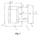
- Fig. 1 shows a system 1 for detecting a failure of a pressure sensor 2, which serves to monitor the pressure of a closed space 3.
- the closed space 3 is in the example shown, the double-wall space of a double-walled tank 4, as it is used, for example, at gas stations as an underground fuel tank and has a withdrawal line 5.
- the space 3 is for example subjected to overpressure, in order to prevent leakage of fuel in the event of a leak in the inner wall of the tank 4.
- the space 3 is alternatively evacuated to a predetermined negative pressure to prevent entry of air into the tank 4 in the event of leakage of the inner wall.
- the compliance with a predetermined pressure range is monitored with the aid of the pressure sensor 2, ie the pressure sensor 2 triggers when leaving this pressure range, eg falling below a minimum pressure of a pressurized space or exceeding a maximum pressure of an evacuated space, as in a leak in the inner or outer wall of the tank can occur, a corresponding alarm.
- an evaluation device 6 which receives the pressure measuring signal of the pressure sensor 2 via a data connection 7 and can output an alarm on an output line 8.
- the system 1 is further equipped with a barometer 9 outside the tank 4, a hygrometer 10 in the room 3 and a level sensor 11 inside the tank, which components are also connected to the evaluation device 6 and whose function will be explained in more detail later.
- a corresponding diurnal pressure fluctuation .DELTA.P in Fig. 2 is shown schematically and varies severely for different seasons: curve 12 shows the daily periodic pressure fluctuation in room 3 on a typical summer day, curve 13 on a typical spring or fall day and curve 14 on a typical winter day. It can be seen that the largest diurnal pressure fluctuations ⁇ P occur in spring and autumn respectively. In any case, the daily periodic pressure fluctuation ⁇ P is usually very small (in Fig. 2 exaggerated) and is always within the pressure range to be monitored by the pressure sensor 2 for alarm purposes.
- Fig. 3 shows an exemplary pressure measurement, which was received by the evaluation device 6 via the data link 7 from the pressure sensor 2 in the period of 09 h 49 min 34 s to 09 h 09 min 34 s of the following day and about the curve 14 of Fig. 2 corresponding course shows.
- the evaluation device 6 determines in its continuous check that the pressure measurement signal had no daily fluctuation in pressure within the last 24 hours, it indicates a failure of the pressure sensor 2, for example by issuing a corresponding failure alarm on the output line 8.
- threshold value S is zero, a failure is detected if there is no daily periodic pressure fluctuation ⁇ P; if S is greater than zero, a failure is detected if the daily periodic pressure fluctuation ⁇ P falls below the threshold value.
- the pressure measurement of the pressure sensor 2 can be optionally adjusted by the evaluation device 6 prior to the above evaluation to fluctuations in the atmospheric pressure, which can be measured by means of the barometer 9.
- the fill level in the tank 4 can also falsify the pressure readings of the pressure sensor 2 if, for example, the inner wall of the tank 4 expands depending on the fill level of the tank.
- the level sensor 11 can therefore optionally the level of the tank 4 is measured and the pressure measurement of the pressure sensor 2 are adjusted by the evaluation device 6 to level-related pressure changes.
- the system and method of the invention are suitable for detecting the failure of all types of pressure sensors which monitor the pressure of a closed space that is at least indirectly subject to the influence of the ambient climate and thus temperature changes during the day, e.g. also of safety pressure sensors for liquid-cooled outdoor transformer stations.
Landscapes
- Health & Medical Sciences (AREA)
- Chemical & Material Sciences (AREA)
- Engineering & Computer Science (AREA)
- Analytical Chemistry (AREA)
- Biomedical Technology (AREA)
- Physics & Mathematics (AREA)
- General Physics & Mathematics (AREA)
- Measuring Fluid Pressure (AREA)
Description
- Die vorliegende Erfindung betrifft eine Anlage zur Ausfallserkennung eines Drucksensors, der zur Drucküberwachung eines geschlossenen Raums dient und ein Verlassen eines vorgegebenen Druckbereichs anzeigt, mit einer Auswerteeinrichtung für das Druckmeßsignal des Drucksensors. Die Erfindung betrifft ferner ein Verfahren für eine solche Ausfallserkennung.
- Drucksensoren für geschlossene Räume dienen häufig als Sicherheitseinrichtungen, beispielsweise zur Drucküberwachung des Doppelwand-Zwischenraums von doppelwandigen Tanks, zur Drucküberwachung von flüssigkeitsgekühlten Gerätegehäusen usw. Bei solchen Sicherheitsanwendungen befindet sich der Drucksensor für lange Zeit, d.h. solange kein Über- oder Unterdruckalarm abzugeben ist, üblicherweise in Ruhestellung und es ist nicht erkennbar, ob der Drucksensor für den Ernstfall noch funktionsfähig oder bereits ausgefallen ist. Eine regelmäßige Überprüfung der Funktionsbereitschaft des Drucksensors ist daher sicherheitsentscheidend, was bislang aufwendig durch Begehungen vor Ort oder periodische Tests durchgeführt werden muß. Darüberhinaus birgt dies die Gefahr in sich, einen zwischen den Oberprüfungsintervallen auftretenden Ausfall nicht sofort zu erkenne Eine Funktionsprüfung einer Sicherheitseinrichtung wird in
-
DE 42 16 937 offenbart. - Die Erfindung setzt sich zum Ziel, eine Anlage und ein Verfahren zur Ausfallserkennung eines Drucksensors zu schaffen, welche die geschilderten Nachteile überwinden und eine ständige Ausfallsüberwachung von in Sicherheitsbereitschaft stehenden Drucksensoren ermöglichen.
- Dieses Ziel wird in einem ersten Aspekt der Erfindung mit einer Anlage der einleitend genannten Art erreicht, die sich dadurch auszeichnet, daß die Auswerteeinrichtung einen Ausfall des Drucksensors anzeigt, wenn das Druckmeßsignal innerhalb des genannten Druckbereichs keine tagesperiodische Druckschwankung aufweist.
- Die Erfindung beruht auf der Erkenntnis, daß der Druck in einem geschlossenen Raum stets einer kleinen, tagesperiodischen Druckschwankung unterliegt, welche auf den Einfluß des natürlichen Umgebungsklimas zurückzuführen ist, u.zw. genauer die unterschiedliche Tag-Nacht-Erwärmung durch die wechselnde Sonneneinstrahlung. Diese geringfügigen Temperaturschwankungen führen zu korrespondierenden geringfügigen Druckschwankungen innerhalb des Raumes im Tagesverlauf, welche nach den Prinzipien der vorliegenden Erfindung als Kriterium für die Funktionsfähigkeit des Drucksensors herangezogen werden: Das Ausbleiben einer tagesperiodischen Schwankung im Druckmeßsignal des Drucksensors zeigt unmittelbar einen Ausfall des Drucksensors an, sodaß sofort Gegenmaßnahmen getroffen werden können. Im Ergebnis ermöglicht dies eine kontinuierliche Ausfallserkennung von Drucksensoren, selbst wenn diese über lange Zeit in bloßer Auslösebereitschaft ("Ruhestellung") stehen. Die Ausfallerkennung ist auch von einem weit entfernten Ort aus möglich, denn es ist dazu lediglich das Druckmeßsignal erforderlich, welches signaltechnische fernüberwacht werden kann.
- Gemäß einer bevorzugten Ausführungsform der Erfindung zeigt die Auswerteeinrichtung auch dann einen Ausfall des Drucksensors an, wenn das Druckmeßsignal eine tagesperiodische Druckschwankung aufweist, die unter einem vorgegebenen Schwellwert liegt. Dadurch kann der Einfluß von Meßwandlertoleranzen im Drucksensor reduziert werden; darüber hinaus kann damit ein nahender Ausfall des Drucksensors erkannt werden, wenn sich dieser durch eine sukzessive Verringerung seiner Meßempfindlichkeit ankündigt.
- Eine weitere bevorzugte Ausführungsform der Erfindung zeichnet sich dadurch aus, daß die Anlage ein Barometer aufweist, welches Änderungen des Atmosphärendrucks außerhalb des Raumes mißt und an die Auswerteeinrichtung angeschlossen ist, und die Auswerteeinrichtung das Druckmeßsignal vor der genannten Auswertung um atmosphärendruckbedingte Druckänderungen bereinigt. Dadurch kann der Einfluß von klimatischen Luftdruckschwankungen kompensiert werden, sodaß die gemessenen Druckschwankungen im wesentlichen nur mehr auf die tagesperiodischen Temperaturschwankungen im Rauminneren zurückzuführen sind, welche durch die wechselnde Sonneneinstrahlung im Tagesverlauf bedingt sind.
- Gemäß einem weiteren bevorzugten Merkmal der Erfindung weist die Anlage ferner ein Hygrometer auf, welches Änderungen des Feuchtigkeitsgehalts im Raum mißt und an die Auswerteeinrichtung angeschlossen ist, und die Auswerteeinrichtung bereinigt das Druckmeßsignal vor der genannten Auswertung um feuchtigkeitsgehaltbedingte Druckänderungen, sodaß auch diese Einflüsse kompensiert werden können.
- Für den bevorzugten Anwendungsfall von Drucksensoren, die als Raum den Doppelwand-Zwischenraum eines doppelwandigen Tanks überwachen, ist es besonders günstig, wenn die Anlage gemäß einem weiteren bevorzugten Merkmal einen Füllstandsensor für den Tank aufweist, welcher an die Auswerteeinrichtung angeschlossen ist, und die Auswerteeinrichtung das Druckmeßsignal vor der genannten Auswertung um füllstandsbedingte Druckänderungen bereinigt. Dadurch können auch Störeinflüsse, die auf Dehnungen der inneren Tankwand der Doppelwand wegen wechselnden Füllstandes auftreten, kompensiert werden.
- In einem zweiten Aspekt schafft die Erfindung ein Verfahren zur Ausfallserkennung der eingangs genannten Art, welches sich dadurch auszeichnet, daß fortlaufend überprüft wird, ob das Druckmeßsignal des Drucksensors innerhalb des genannten Druckbereichs eine tagesperiodische Druckschwankung aufweist, und ein Ausfall des Drucksensors erkannt wird, wenn keine tagesperiodische Druckschwankung mehr feststellbar ist. Hinsichtlich der Vorteile des erfindungsgemäßen Verfahrens wird auf die obigen Ausführungen zur Anlage verwiesen.
- Bevorzugt wird ein Ausfall des Drucksensors bereits dann erkannt, wenn die tagesperiodische Druckschwankung unter einen vorgegebenen Schwellwert fällt; und besonders bevorzugt wird als Schwellwert ein Bruchteil des Mittelwerts mehrerer vorangegangener tagesperiodischer Druckschwankungen festgesetzt. Dadurch kann ein weitgehend automatisiertes Verfahren geschaffen werden, dessen Auslösekriterium für die Ausfallserkennung keiner manuellen Einstellung bedarf, sondern sich anlagenspezifisch selbsttätig einstellt.
- Weitere Merkmale und Vorteile der Erfindung ergeben sich aus der nachstehenden Beschreibung eines bevorzugten Ausführungsbeispieles anhand der beigeschlossenen Zeichnungen, in denen zeigt:
-
Fig. 1 die Anlage der Erfindung in schematischer Blockschaltbildform; -
Fig. 2 drei jahreszeitentypische Druckschwankungsverläufe in einem geschlossenen Raum, welcher dem natürlichen Umgebungsklima ausgesetzt ist; und -
Fig. 3 ein beispielhaftes tagesperiodisches Druckmeßsignal des Drucksensors vonFig. 1 . -
Fig. 1 zeigt eine Anlage 1 zur Erkennung eines Ausfalles eines Drucksensors 2, welcher zur Drucküberwachung eines geschlossenen Raumes 3 dient. Der geschlossene Raum 3 ist im gezeigten Beispiel der Doppelwand-Zwischenraum eines doppelwandigen Tanks 4, wie er beispielsweise bei Tankstellen als unterirdischer Kraftstofftank Anwendung findet und über eine Entnahmeleitung 5 verfügt. Der Raum 3 wird beispielsweise mit Überdruck beaufschlagt, um im Falle eines Lecks der Innenwand des Tanks 4 ein Austreten von Kraftstoff zu verhindern. Bei anderen Anwendungsfällen wird der Raum 3 alternativ auf einen vorgegebenen Unterdruck evakuiert, um im Falle eines Lecks der Innenwand ein Eintreten von Luft in den Tank 4 zu verhindern. In jedem Fall wird mit Hilfe des Drucksensors 2 die Einhaltung eines vorgegebenen Druckbereichs überwacht, d.h. der Drucksensor 2 löst bei einem Verlassen dieses Druckbereichs, z.B. einem Unterschreiten eines Mindestdrucks eines druckbeaufschlagten Raumes oder einem Überschreiten eines Höchstdrucks eines evakuierten Raumes, wie es bei einem Leck in der Innen- oder Außenwand des Tanks auftreten kann, einen entsprechenden Alarm aus. Dazu dient im gezeigten Beispiel eine Auswerteeinrichtung 6, welche über eine Datenverbindung 7 das Druckmeßsignal des Drucksensors 2 empfängt und auf einer Ausgangsleitung 8 einen Alarm ausgeben kann. - Die Anlage 1 ist ferner mit einem Barometer 9 außerhalb des Tanks 4, einem Hygrometer 10 im Raum 3 sowie einem Füllstandsensor 11 im Tankinneren ausgestattet, welche Komponenten ebenfalls an die Auswerteeinrichtung 6 angeschlossen sind und deren Funktion später ausführlicher erläutert wird.
- Zur ständigen Überprüfung der Funktionsbereitschaft und damit Erkennung eines Ausfalls des Drucksensors 2 dient das folgende Verfahren, welches von der Auswerteeinrichtung 6 abgearbeitet wird.
- Aufgrund der im Tagesverlauf wechselnden Sonneneinstrahlung auf den Tank 4, welche zu einer entsprechenden tagesperiodischen Temperaturschwankung der Gase im Raum 3 führt, tritt im Raum 3 eine dementsprechende tagesperiodische Druckschwankung ΔP auf, die in
Fig. 2 schematisch gezeigt ist und für unterschiedliche Jahreszeiten unterschiedlich stark ausfällt: Kurve 12 zeigt die tagesperiodische Druckschwankung im Raum 3 an einem typischen Sommertag, Kurve 13 an einem typischen Frühlings- oder Herbsttag und Kurve 14 an einem typischen Wintertag. Es ist ersichtlich, daß die größte tagesperiodische Druckschwankungen ΔP im Frühling bzw. Herbst auftritt. In jedem Fall ist die tagesperiodische Druckschwankung ΔP in der Regel sehr klein (inFig. 2 übertrieben dargestellt) und liegt stets innerhalb des vom Drucksensor 2 zu Alarmzwecken zu überwachenden Druckbereichs. - Das Auftreten der tagesperiodischen Druckschwankung ΔP im Druckmeßsignal des Drucksensors 2 wird von der Auswerteeinrichtung 6 kontinuierlich, beispielsweise einmal pro Tag für die vorangegangenen 24h, festgestellt.
Fig. 3 zeigt ein beispielhaftes Druckmeßsignal, das von der Auswerteeinrichtung 6 über die Datenverbindung 7 vom Drucksensor 2 im Zeitraum von 09 h 49 min 34 s bis 09 h 09 min 34 s des Folgetages empfangen wurde und einen etwa der Kurve 14 vonFig. 2 entsprechenden Verlauf zeigt. - Sobald die Auswerteeinrichtung 6 bei ihrer fortlaufenden Überprüfung feststellt, daß das Druckmeßsignal innerhalb der letzten 24h keine tagesperiodische Druckschwankung aufwies, zeigt sie einen Ausfall des Drucksensors 2 an, beispielsweise durch Abgabe eines entsprechenden Ausfallalarmes auf der Ausgangsleitung 8.
- Das Erkennen des Vorliegens einer tagesperiodischen Druckschwankung im Druckmeßsignal kann mit Hilfe jedes beliebigen in der Technik bekannten Signalauswertungsverfahrens vorgenommen werden, beispielsweise durch Frequenzanalyse, Mustererkennung od.dgl. Im einfachsten Fall genügt es, die Differenz zwischen maximalem und minimalem Druckmeßwert eines Tages zu ermitteln, d.h. die Amplitude ΔP der tagesperiodischen Druckschwankung, und festzustellen, ob diese Null ist oder zumindest einen vorgegebenen Schwellwert unterschreitet, d.h. das Kriterium ist:

mitPmax24h ............ maximaler Druckmeßwert der letzten 24 Stunden Pmin24h ............ minimaler Druckmeßwert der letzten 24 Stunden S ........................ vorgegebener Schwellwert - Wenn der Schwellwert S Null ist, wird auf einen Ausfall erkannt, wenn keine tagesperiodische Druckschwankung ΔP vorliegt; wenn S größer als Null ist, wird auf einen Ausfall erkannt, wenn die tagesperiodische Druckschwankung ΔP den Schwellwert unterschreitet.
- Bevorzugt wird der Schwellwert S auf einen vorgegebenen Bruchteil, z.B. 1/10, des Mittelwertes ΔPmittel mehrerer vorangegangener tagesperiodischer Druckschwankungen ΔP festgesetzt, d.h.

- Der Druckmeßwert des Drucksensors 2 kann von der Auswerteeinrichtung 6 vor der obengenannten Auswertung optional um Schwankungen des atmosphärischen Umgebungsdrucks bereinigt werden, welche mittels des Barometers 9 gemessen werden können.
- Auch Änderungen des Feuchtigkeitsgehalts der Gase im Raum 3, die einen störenden Einfluß auf den Druckmeßwert haben können, können optional mittels des Hygrometers 10 gemessen und von der Auswerteeinrichtung 6 unter Heranziehung der in der Technik bekannten Gasgleichungen kompensiert werden.
- Schließlich kann auch der Füllstand im Tank 4 die Druckmeßwerte des Drucksensors 2 verfälschen, wenn sich beispielsweise die Innenwand des Tanks 4 je nach Füllstands des Tanks ausdehnt. Mittels des Füllstandsensors 11 kann daher optional der Füllstand des Tanks 4 gemessen und das Druckmeßsignal des Drucksensors 2 von der Auswerteeinrichtung 6 um füllstandsbedingten Druckänderungen bereinigt werden.
- Die Anlage und das Verfahren der Erfindung eignen sich zur Ausfallserkennung aller Arten von Drucksensoren, welche den Druck eines geschlossenen Raumes überwachen, der zumindest indirekt dem Einfluß des Umgebungsklimas und damit Temperaturänderungen im Tagesverlauf unterliegt, z.B. auch von Sicherheits-Drucksensoren für flüssigkeitsgekühlte Freiland-Transformatorstationen.
- Die Erfindung ist demgemäß nicht auf die dargestellten Ausführungsbeispiele beschränkt, sondern umfaßt alle Varianten und Modifikationen, die in den Rahmen der angeschlossenen Ansprüche fallen.
Claims (10)
- Anlage (1) zur Ausfallserkennung eines Drucksensors (2), der zur Drucküberwachung eines geschlossenen Raums (3) dient und ein Verlassen eines vorgegebenen Druckbereichs anzeigt, mit einer Auswerteeinrichtung für das Druckmeßsignal des Drucksensors, dadurch gekennzeichnet, daß die Auswerteeinrichtung (6) einen Ausfall des Drucksensors (2) anzeigt, wenn das Druckmeßsignal innerhalb des genannten Druckbereichs keine tagesperiodische Druckschwankung (ΔP) aufweist.
- Anlage nach Anspruch 1, dadurch gekennzeichnet, daß die Auswerteeinrichtung (6) auch dann einen Ausfall des Drucksensors (2) anzeigt, wenn das Druckmeßsignal eine tagesperiodische Druckschwankung (ΔP) aufweist, die unter einem vorgegebenen Schwellwert (S) liegt.
- Anlage nach Anspruch 1 oder 2, dadurch gekennzeichnet, daß sie ein Barometer (9) aufweist, welches Änderungen des Atmosphärendrucks außerhalb des Raumes (3) mißt und an die Auswerteeinrichtung (6) angeschlossen ist, und daß die Auswerteeinrichtung (6) das Druckmeßsignal vor der genannten Auswertung um atmosphärendruckbedingte Druckänderungen bereinigt.
- Anlage nach einem der Ansprüche 1 bis 3, dadurch gekennzeichnet, daß sie ein Hygrometer (10) aufweist, welches Änderungen des Feuchtigkeitsgehalts im Raum (3) mißt und an die Auswerteeinrichtung (6) angeschlossen ist, und daß die Auswerteeinrichtung (6) das Druckmeßsignal vor der genannten Auswertung um feuchtigkeitsgehaltbedingte Druckänderungen bereinigt.
- Anlage nach einem der Ansprüche 1 bis 4 für einen Drucksensor (2), der als Raum (3) den Doppelwand-Zwischenraum eines doppelwandigen Tanks (4) überwacht, dadurch gekennzeichnet, daß sie einen Füllstandsensor (11) für den Tank (4) aufweist, welcher an die Auswerteeinrichtung (6) angeschlossen ist, und daß die Auswerteeinrichtung (6) das Druckmeßsignal vor der genannten Auswertung um füllstandsbedingte Druckänderungen bereinigt.
- Verfahren zur Ausfallserkennung eines Drucksensors, der zur Drucküberwachung eines geschlossenen Raums dient und ein Verlassen eines vorgegebenen Druckbereichs anzeigt, dadurch gekennzeichnet, daß fortlaufend überprüft wird, ob das Druckmeßsignal des Drucksensors (2) innerhalb des genannten Druckbereichs eine tagesperiodische Druckschwankung (ΔP) aufweist, und ein Ausfall des Drucksensors (2) erkannt wird, wenn keine tagesperiodische Druckschwankung (ΔP) mehr feststellbar ist.
- Verfahren nach Anspruch 6, dadurch gekennzeichnet, daß ein Ausfall des Drucksensors (2) bereits dann erkannt wird, wenn die tagesperiodische Druckschwankung (ΔP) unter einen vorgegebenen Schwellwert (S) fällt.
- Verfahren nach Anspruch 7, dadurch gekennzeichnet, daß als Schwellwert (S) ein Bruchteil des Mittelwerts mehrerer vorangegangener tagesperiodischer Druckschwankungen festgesetzt wird.
- Verfahren nach einem der Ansprüche 6 bis 8, dadurch gekennzeichnet, daß das Druckmeßsignal vor der genannten Überprüfung um atmosphärendruckbedingte Druckänderungen bereinigt wird, die mittels eines Barometers (9) außerhalb des Raums (3) gemessen werden.
- Verfahren nach einem der Ansprüche 6 bis 9, dadurch gekennzeichnet, daß das Druckmeßsignal vor der genannten Überprüfung um feuchtigkeitsgehaltbedingte Druckänderungen im Raum bereinigt wird, die mittels eines Hygrometers (10) im Raum (3) gemessen werden.
Applications Claiming Priority (2)
| Application Number | Priority Date | Filing Date | Title |
|---|---|---|---|
| AT6782008A AT506597B1 (de) | 2008-04-30 | 2008-04-30 | Anlage und verfahren zur ausfallserkennung eines drucksensors |
| PCT/AT2009/000171 WO2009132366A1 (de) | 2008-04-30 | 2009-04-28 | Anlage und verfahren zur ausfallserkennung eines drucksensors |
Publications (2)
| Publication Number | Publication Date |
|---|---|
| EP2279399A1 EP2279399A1 (de) | 2011-02-02 |
| EP2279399B1 true EP2279399B1 (de) | 2013-01-02 |
Family
ID=40810717
Family Applications (1)
| Application Number | Title | Priority Date | Filing Date |
|---|---|---|---|
| EP09737518A Active EP2279399B1 (de) | 2008-04-30 | 2009-04-28 | Anlage und verfahren zur ausfallserkennung eines drucksensors |
Country Status (3)
| Country | Link |
|---|---|
| EP (1) | EP2279399B1 (de) |
| AT (1) | AT506597B1 (de) |
| WO (1) | WO2009132366A1 (de) |
Cited By (1)
| Publication number | Priority date | Publication date | Assignee | Title |
|---|---|---|---|---|
| US20150233880A1 (en) * | 2014-02-14 | 2015-08-20 | Rosemount Analytical Inc. | Solid state gas detection sensor diagnostic |
Families Citing this family (1)
| Publication number | Priority date | Publication date | Assignee | Title |
|---|---|---|---|---|
| DE102023205811A1 (de) * | 2023-06-21 | 2024-12-24 | Robert Bosch Gesellschaft mit beschränkter Haftung | Drucksensormodul und Verfahren zum Messen eines Drucks |
Family Cites Families (4)
| Publication number | Priority date | Publication date | Assignee | Title |
|---|---|---|---|---|
| US2510402A (en) * | 1948-03-15 | 1950-06-06 | Robert M Johnston | Barometer |
| DE4216937A1 (de) * | 1992-05-22 | 1993-11-25 | Rietbergwerke Gmbh & Co Kg | Doppelwandiger Flüssigkeitsbehälter mit Leckanzeigevorrichtung |
| US7712352B2 (en) * | 2004-07-07 | 2010-05-11 | Mass Technology Corporation | Method and apparatus for storage tank leak detection |
| KR100598853B1 (ko) * | 2004-12-23 | 2006-07-11 | 현대자동차주식회사 | 압력센서의 고장 판단방법 |
-
2008
- 2008-04-30 AT AT6782008A patent/AT506597B1/de not_active IP Right Cessation
-
2009
- 2009-04-28 WO PCT/AT2009/000171 patent/WO2009132366A1/de not_active Ceased
- 2009-04-28 EP EP09737518A patent/EP2279399B1/de active Active
Cited By (2)
| Publication number | Priority date | Publication date | Assignee | Title |
|---|---|---|---|---|
| US20150233880A1 (en) * | 2014-02-14 | 2015-08-20 | Rosemount Analytical Inc. | Solid state gas detection sensor diagnostic |
| US9709544B2 (en) * | 2014-02-14 | 2017-07-18 | Rosemount Analytical Inc. | Solid state gas detection sensor diagnostic |
Also Published As
| Publication number | Publication date |
|---|---|
| AT506597B1 (de) | 2009-10-15 |
| AT506597A4 (de) | 2009-10-15 |
| WO2009132366A1 (de) | 2009-11-05 |
| EP2279399A1 (de) | 2011-02-02 |
Similar Documents
| Publication | Publication Date | Title |
|---|---|---|
| DE102011086486B4 (de) | Vorrichtung und Verfahren zur schnellen Lecksuche an formsteifen/schlaffen Verpackungen ohne Zusatz von Prüfgas | |
| DE102012216036B4 (de) | Verfahren und system zum überwachen des zustands einer flüssigkeitstransportleitung | |
| DE102009026744B4 (de) | Verfahren zur Dichtheitsprüfung von Bauteilen | |
| EP3394588B1 (de) | Grobleckmessung eines inkompressiblen prüflings in einer folienkammer | |
| DE69619415T2 (de) | Verfahren zur Leckprüfung von Rohren und Gerät zur Leckprüfung | |
| DE102018215655B4 (de) | Hochvoltbatterie für ein Kraftfahrzeug mit einer Überwachungsvorrichtung zum Überwachen einer Dichtigkeit eines Batteriegehäuses sowie Kraftfahrzeug | |
| WO2016041893A1 (de) | Folienkammer mit messvolumen zur grobleckerkennung | |
| DE10210925A1 (de) | Verfahren zur Überprüfung der Funktionsfähigkeit eines Drucksensors | |
| EP1928675B1 (de) | Verfahren und vorrichtung zur erkennung von leckagen in einer kraftfahrzeug-luftfederanordnung | |
| DE102013203187A1 (de) | Verfahren und Vorrichtung zur Ermittlung der Füllmasse eines kryogen gespeicherten Gases in einem Behälter | |
| EP2914944B1 (de) | Verfahren zur prüfung einer dichtheitsprüfanlage | |
| DE19503311B4 (de) | Vorrichtung zum Prüfen von Filterelementen durch einen Wasserintrusionstest | |
| AT506597B1 (de) | Anlage und verfahren zur ausfallserkennung eines drucksensors | |
| EP0894250A1 (de) | Verfahren und einrichtung zum prüfen der festigkeit von stehend verankerten masten | |
| DE102018114256A1 (de) | Verfahren und system zum erkennen eines fehlerzustands in der messung des füllstands eines mediums in einem tank | |
| EP1273902A2 (de) | Gerät und Verfahren zur Messung der Gasdurchlässigkeit eines porösen Baustoffs | |
| DE102004030766B4 (de) | Prüfsystem und Verfahren zur Messung der Dichtheit von Handschuhen, insbesondere in pharmazeutischen Anlagen | |
| EP3676579A1 (de) | Differenzdruckmessanordnung | |
| EP3812645A1 (de) | Vorrichtung zum ermitteln eines verbrauchs eines gases aus einer zumindest teilweise mit gas gefüllten gasflasche | |
| WO2018054686A1 (de) | Tragbare vorrichtung zum diagnostizieren eines prozessfluidführenden stellgeräts und verfahren zur diagnose des zustands eines prozessfluidführenden stellgeräts | |
| DE102008005672B4 (de) | Vorrichtung und Verfahren zum Erfassen von Strukturveränderungen eines Bauteils | |
| DE102015122594A1 (de) | Bauteilvorrichtung und Verfahren zum Detektieren eines Schadens einer Verklebung bei einer Bauteilvorrichtung | |
| DE102004012534A1 (de) | Verfahren und Vorrichtung zum Feststellen der Dichtigkeit von geschlossenen Behältnissen oder Prüflingen | |
| EP1473557B1 (de) | Verfahren und Vorrichtung zur Biegeprüfung von Masten und ähnlich stehend verankerten Systemen | |
| EP0889305A2 (de) | Verfahren und Vorrichtung zur Prüfung von Druckgasflaschen |
Legal Events
| Date | Code | Title | Description |
|---|---|---|---|
| PUAI | Public reference made under article 153(3) epc to a published international application that has entered the european phase |
Free format text: ORIGINAL CODE: 0009012 |
|
| 17P | Request for examination filed |
Effective date: 20100927 |
|
| AK | Designated contracting states |
Kind code of ref document: A1 Designated state(s): AT BE BG CH CY CZ DE DK EE ES FI FR GB GR HR HU IE IS IT LI LT LU LV MC MK MT NL NO PL PT RO SE SI SK TR |
|
| AX | Request for extension of the european patent |
Extension state: AL BA RS |
|
| RAP1 | Party data changed (applicant data changed or rights of an application transferred) |
Owner name: ONO OIL GMBH |
|
| DAX | Request for extension of the european patent (deleted) | ||
| GRAP | Despatch of communication of intention to grant a patent |
Free format text: ORIGINAL CODE: EPIDOSNIGR1 |
|
| GRAS | Grant fee paid |
Free format text: ORIGINAL CODE: EPIDOSNIGR3 |
|
| GRAA | (expected) grant |
Free format text: ORIGINAL CODE: 0009210 |
|
| RAP1 | Party data changed (applicant data changed or rights of an application transferred) |
Owner name: ONO OIL GMBH |
|
| AK | Designated contracting states |
Kind code of ref document: B1 Designated state(s): AT BE BG CH CY CZ DE DK EE ES FI FR GB GR HR HU IE IS IT LI LT LU LV MC MK MT NL NO PL PT RO SE SI SK TR |
|
| REG | Reference to a national code |
Ref country code: GB Ref legal event code: FG4D Free format text: NOT ENGLISH |
|
| REG | Reference to a national code |
Ref country code: CH Ref legal event code: EP Ref country code: AT Ref legal event code: REF Ref document number: 591860 Country of ref document: AT Kind code of ref document: T Effective date: 20130115 |
|
| REG | Reference to a national code |
Ref country code: IE Ref legal event code: FG4D Free format text: LANGUAGE OF EP DOCUMENT: GERMAN |
|
| REG | Reference to a national code |
Ref country code: DE Ref legal event code: R096 Ref document number: 502009005877 Country of ref document: DE Effective date: 20130307 |
|
| REG | Reference to a national code |
Ref country code: CH Ref legal event code: NV Representative=s name: PATWIL AG, CH |
|
| REG | Reference to a national code |
Ref country code: NL Ref legal event code: VDEP Effective date: 20130102 |
|
| PG25 | Lapsed in a contracting state [announced via postgrant information from national office to epo] |
Ref country code: SI Free format text: LAPSE BECAUSE OF FAILURE TO SUBMIT A TRANSLATION OF THE DESCRIPTION OR TO PAY THE FEE WITHIN THE PRESCRIBED TIME-LIMIT Effective date: 20130102 |
|
| REG | Reference to a national code |
Ref country code: LT Ref legal event code: MG4D |
|
| PG25 | Lapsed in a contracting state [announced via postgrant information from national office to epo] |
Ref country code: NO Free format text: LAPSE BECAUSE OF FAILURE TO SUBMIT A TRANSLATION OF THE DESCRIPTION OR TO PAY THE FEE WITHIN THE PRESCRIBED TIME-LIMIT Effective date: 20130402 Ref country code: ES Free format text: LAPSE BECAUSE OF FAILURE TO SUBMIT A TRANSLATION OF THE DESCRIPTION OR TO PAY THE FEE WITHIN THE PRESCRIBED TIME-LIMIT Effective date: 20130413 Ref country code: LT Free format text: LAPSE BECAUSE OF FAILURE TO SUBMIT A TRANSLATION OF THE DESCRIPTION OR TO PAY THE FEE WITHIN THE PRESCRIBED TIME-LIMIT Effective date: 20130102 Ref country code: SE Free format text: LAPSE BECAUSE OF FAILURE TO SUBMIT A TRANSLATION OF THE DESCRIPTION OR TO PAY THE FEE WITHIN THE PRESCRIBED TIME-LIMIT Effective date: 20130102 Ref country code: IS Free format text: LAPSE BECAUSE OF FAILURE TO SUBMIT A TRANSLATION OF THE DESCRIPTION OR TO PAY THE FEE WITHIN THE PRESCRIBED TIME-LIMIT Effective date: 20130502 Ref country code: BG Free format text: LAPSE BECAUSE OF FAILURE TO SUBMIT A TRANSLATION OF THE DESCRIPTION OR TO PAY THE FEE WITHIN THE PRESCRIBED TIME-LIMIT Effective date: 20130402 Ref country code: CZ Free format text: LAPSE BECAUSE OF FAILURE TO SUBMIT A TRANSLATION OF THE DESCRIPTION OR TO PAY THE FEE WITHIN THE PRESCRIBED TIME-LIMIT Effective date: 20130102 |
|
| PG25 | Lapsed in a contracting state [announced via postgrant information from national office to epo] |
Ref country code: PL Free format text: LAPSE BECAUSE OF FAILURE TO SUBMIT A TRANSLATION OF THE DESCRIPTION OR TO PAY THE FEE WITHIN THE PRESCRIBED TIME-LIMIT Effective date: 20130102 Ref country code: FI Free format text: LAPSE BECAUSE OF FAILURE TO SUBMIT A TRANSLATION OF THE DESCRIPTION OR TO PAY THE FEE WITHIN THE PRESCRIBED TIME-LIMIT Effective date: 20130102 Ref country code: NL Free format text: LAPSE BECAUSE OF FAILURE TO SUBMIT A TRANSLATION OF THE DESCRIPTION OR TO PAY THE FEE WITHIN THE PRESCRIBED TIME-LIMIT Effective date: 20130102 Ref country code: GR Free format text: LAPSE BECAUSE OF FAILURE TO SUBMIT A TRANSLATION OF THE DESCRIPTION OR TO PAY THE FEE WITHIN THE PRESCRIBED TIME-LIMIT Effective date: 20130403 Ref country code: LV Free format text: LAPSE BECAUSE OF FAILURE TO SUBMIT A TRANSLATION OF THE DESCRIPTION OR TO PAY THE FEE WITHIN THE PRESCRIBED TIME-LIMIT Effective date: 20130102 Ref country code: PT Free format text: LAPSE BECAUSE OF FAILURE TO SUBMIT A TRANSLATION OF THE DESCRIPTION OR TO PAY THE FEE WITHIN THE PRESCRIBED TIME-LIMIT Effective date: 20130502 |
|
| PG25 | Lapsed in a contracting state [announced via postgrant information from national office to epo] |
Ref country code: HR Free format text: LAPSE BECAUSE OF FAILURE TO SUBMIT A TRANSLATION OF THE DESCRIPTION OR TO PAY THE FEE WITHIN THE PRESCRIBED TIME-LIMIT Effective date: 20130102 |
|
| BERE | Be: lapsed |
Owner name: ONO OIL GMBH Effective date: 20130430 |
|
| PG25 | Lapsed in a contracting state [announced via postgrant information from national office to epo] |
Ref country code: RO Free format text: LAPSE BECAUSE OF FAILURE TO SUBMIT A TRANSLATION OF THE DESCRIPTION OR TO PAY THE FEE WITHIN THE PRESCRIBED TIME-LIMIT Effective date: 20130102 Ref country code: EE Free format text: LAPSE BECAUSE OF FAILURE TO SUBMIT A TRANSLATION OF THE DESCRIPTION OR TO PAY THE FEE WITHIN THE PRESCRIBED TIME-LIMIT Effective date: 20130102 Ref country code: SK Free format text: LAPSE BECAUSE OF FAILURE TO SUBMIT A TRANSLATION OF THE DESCRIPTION OR TO PAY THE FEE WITHIN THE PRESCRIBED TIME-LIMIT Effective date: 20130102 Ref country code: DK Free format text: LAPSE BECAUSE OF FAILURE TO SUBMIT A TRANSLATION OF THE DESCRIPTION OR TO PAY THE FEE WITHIN THE PRESCRIBED TIME-LIMIT Effective date: 20130102 |
|
| PLBE | No opposition filed within time limit |
Free format text: ORIGINAL CODE: 0009261 |
|
| STAA | Information on the status of an ep patent application or granted ep patent |
Free format text: STATUS: NO OPPOSITION FILED WITHIN TIME LIMIT |
|
| PG25 | Lapsed in a contracting state [announced via postgrant information from national office to epo] |
Ref country code: MC Free format text: LAPSE BECAUSE OF FAILURE TO SUBMIT A TRANSLATION OF THE DESCRIPTION OR TO PAY THE FEE WITHIN THE PRESCRIBED TIME-LIMIT Effective date: 20130102 Ref country code: CY Free format text: LAPSE BECAUSE OF FAILURE TO SUBMIT A TRANSLATION OF THE DESCRIPTION OR TO PAY THE FEE WITHIN THE PRESCRIBED TIME-LIMIT Effective date: 20130102 |
|
| 26N | No opposition filed |
Effective date: 20131003 |
|
| REG | Reference to a national code |
Ref country code: DE Ref legal event code: R097 Ref document number: 502009005877 Country of ref document: DE Effective date: 20131003 |
|
| REG | Reference to a national code |
Ref country code: IE Ref legal event code: MM4A |
|
| PG25 | Lapsed in a contracting state [announced via postgrant information from national office to epo] |
Ref country code: BE Free format text: LAPSE BECAUSE OF NON-PAYMENT OF DUE FEES Effective date: 20130430 |
|
| REG | Reference to a national code |
Ref country code: DE Ref legal event code: R082 Ref document number: 502009005877 Country of ref document: DE Representative=s name: RIECHELMANN & CARLSOHN, DE |
|
| REG | Reference to a national code |
Ref country code: CH Ref legal event code: PK Free format text: BERICHTIGUNG INHABER Ref country code: CH Ref legal event code: PFA Owner name: WOLFTANK ADISA GMBH, AU Free format text: FORMER OWNER: ONO OIL GMBH, AT |
|
| REG | Reference to a national code |
Ref country code: DE Ref legal event code: R082 Ref document number: 502009005877 Country of ref document: DE Representative=s name: RIECHELMANN & CARLSOHN, DE Effective date: 20140307 Ref country code: DE Ref legal event code: R081 Ref document number: 502009005877 Country of ref document: DE Owner name: WOLFTANK ADISA GMBH, AT Free format text: FORMER OWNER: ONO OIL GMBH, INNSBRUCK, AT Effective date: 20140307 Ref country code: DE Ref legal event code: R082 Ref document number: 502009005877 Country of ref document: DE Representative=s name: RIECHELMANN & CARLSOHN GBR, DE Effective date: 20140307 Ref country code: DE Ref legal event code: R082 Ref document number: 502009005877 Country of ref document: DE Representative=s name: RIECHELMANN & CARLSOHN PATENTANWAELTE PARTG MB, DE Effective date: 20140307 |
|
| PG25 | Lapsed in a contracting state [announced via postgrant information from national office to epo] |
Ref country code: IE Free format text: LAPSE BECAUSE OF NON-PAYMENT OF DUE FEES Effective date: 20130428 |
|
| REG | Reference to a national code |
Ref country code: FR Ref legal event code: CD Owner name: WOLFTANK ADISA GMBH, AT Effective date: 20140328 Ref country code: FR Ref legal event code: CA Effective date: 20140328 |
|
| REG | Reference to a national code |
Ref country code: AT Ref legal event code: HC Ref document number: 591860 Country of ref document: AT Kind code of ref document: T Owner name: WOLFTANK ADISA GMBH, AT Effective date: 20140516 |
|
| PGFP | Annual fee paid to national office [announced via postgrant information from national office to epo] |
Ref country code: GB Payment date: 20140423 Year of fee payment: 6 |
|
| PG25 | Lapsed in a contracting state [announced via postgrant information from national office to epo] |
Ref country code: MT Free format text: LAPSE BECAUSE OF FAILURE TO SUBMIT A TRANSLATION OF THE DESCRIPTION OR TO PAY THE FEE WITHIN THE PRESCRIBED TIME-LIMIT Effective date: 20130102 |
|
| REG | Reference to a national code |
Ref country code: FR Ref legal event code: PLFP Year of fee payment: 7 |
|
| PG25 | Lapsed in a contracting state [announced via postgrant information from national office to epo] |
Ref country code: TR Free format text: LAPSE BECAUSE OF FAILURE TO SUBMIT A TRANSLATION OF THE DESCRIPTION OR TO PAY THE FEE WITHIN THE PRESCRIBED TIME-LIMIT Effective date: 20130102 |
|
| PG25 | Lapsed in a contracting state [announced via postgrant information from national office to epo] |
Ref country code: MK Free format text: LAPSE BECAUSE OF FAILURE TO SUBMIT A TRANSLATION OF THE DESCRIPTION OR TO PAY THE FEE WITHIN THE PRESCRIBED TIME-LIMIT Effective date: 20130102 Ref country code: HU Free format text: LAPSE BECAUSE OF FAILURE TO SUBMIT A TRANSLATION OF THE DESCRIPTION OR TO PAY THE FEE WITHIN THE PRESCRIBED TIME-LIMIT; INVALID AB INITIO Effective date: 20090428 Ref country code: LU Free format text: LAPSE BECAUSE OF NON-PAYMENT OF DUE FEES Effective date: 20130428 |
|
| PGFP | Annual fee paid to national office [announced via postgrant information from national office to epo] |
Ref country code: CH Payment date: 20150422 Year of fee payment: 7 |
|
| GBPC | Gb: european patent ceased through non-payment of renewal fee |
Effective date: 20150428 |
|
| PG25 | Lapsed in a contracting state [announced via postgrant information from national office to epo] |
Ref country code: GB Free format text: LAPSE BECAUSE OF NON-PAYMENT OF DUE FEES Effective date: 20150428 |
|
| REG | Reference to a national code |
Ref country code: FR Ref legal event code: PLFP Year of fee payment: 8 |
|
| REG | Reference to a national code |
Ref country code: CH Ref legal event code: PL |
|
| PG25 | Lapsed in a contracting state [announced via postgrant information from national office to epo] |
Ref country code: LI Free format text: LAPSE BECAUSE OF NON-PAYMENT OF DUE FEES Effective date: 20160430 Ref country code: CH Free format text: LAPSE BECAUSE OF NON-PAYMENT OF DUE FEES Effective date: 20160430 |
|
| REG | Reference to a national code |
Ref country code: FR Ref legal event code: PLFP Year of fee payment: 9 |
|
| PGFP | Annual fee paid to national office [announced via postgrant information from national office to epo] |
Ref country code: FR Payment date: 20170424 Year of fee payment: 9 |
|
| PG25 | Lapsed in a contracting state [announced via postgrant information from national office to epo] |
Ref country code: FR Free format text: LAPSE BECAUSE OF NON-PAYMENT OF DUE FEES Effective date: 20180430 |
|
| PGFP | Annual fee paid to national office [announced via postgrant information from national office to epo] |
Ref country code: DE Payment date: 20200423 Year of fee payment: 12 |
|
| PGFP | Annual fee paid to national office [announced via postgrant information from national office to epo] |
Ref country code: AT Payment date: 20200317 Year of fee payment: 12 |
|
| REG | Reference to a national code |
Ref country code: DE Ref legal event code: R119 Ref document number: 502009005877 Country of ref document: DE |
|
| REG | Reference to a national code |
Ref country code: AT Ref legal event code: MM01 Ref document number: 591860 Country of ref document: AT Kind code of ref document: T Effective date: 20210428 |
|
| PG25 | Lapsed in a contracting state [announced via postgrant information from national office to epo] |
Ref country code: AT Free format text: LAPSE BECAUSE OF NON-PAYMENT OF DUE FEES Effective date: 20210428 Ref country code: DE Free format text: LAPSE BECAUSE OF NON-PAYMENT OF DUE FEES Effective date: 20211103 |
|
| P01 | Opt-out of the competence of the unified patent court (upc) registered |
Effective date: 20230427 |
|
| PGFP | Annual fee paid to national office [announced via postgrant information from national office to epo] |
Ref country code: IT Payment date: 20250422 Year of fee payment: 17 |