EP2279150B1 - A slosh controlled personal hydration system - Google Patents
A slosh controlled personal hydration system Download PDFInfo
- Publication number
- EP2279150B1 EP2279150B1 EP09712275A EP09712275A EP2279150B1 EP 2279150 B1 EP2279150 B1 EP 2279150B1 EP 09712275 A EP09712275 A EP 09712275A EP 09712275 A EP09712275 A EP 09712275A EP 2279150 B1 EP2279150 B1 EP 2279150B1
- Authority
- EP
- European Patent Office
- Prior art keywords
- hydration
- reservoir
- baffle
- backpack
- baffles
- Prior art date
- Legal status (The legal status is an assumption and is not a legal conclusion. Google has not performed a legal analysis and makes no representation as to the accuracy of the status listed.)
- Not-in-force
Links
- 230000036571 hydration Effects 0.000 title claims description 144
- 238000006703 hydration reaction Methods 0.000 title claims description 144
- 239000007788 liquid Substances 0.000 claims description 42
- 230000006835 compression Effects 0.000 claims description 12
- 238000007906 compression Methods 0.000 claims description 12
- 239000012530 fluid Substances 0.000 claims description 7
- 229910000831 Steel Inorganic materials 0.000 claims description 2
- 230000000887 hydrating effect Effects 0.000 claims description 2
- 239000010959 steel Substances 0.000 claims description 2
- 230000035622 drinking Effects 0.000 description 14
- 239000000463 material Substances 0.000 description 9
- 238000000034 method Methods 0.000 description 5
- 210000004243 sweat Anatomy 0.000 description 4
- 230000007423 decrease Effects 0.000 description 2
- 230000000694 effects Effects 0.000 description 2
- 238000007710 freezing Methods 0.000 description 2
- 230000008014 freezing Effects 0.000 description 2
- 239000011148 porous material Substances 0.000 description 2
- 241000270272 Coluber Species 0.000 description 1
- 241001272996 Polyphylla fullo Species 0.000 description 1
- 241000792914 Valeriana Species 0.000 description 1
- 238000004140 cleaning Methods 0.000 description 1
- 238000010276 construction Methods 0.000 description 1
- 239000002826 coolant Substances 0.000 description 1
- 239000006260 foam Substances 0.000 description 1
- 230000005484 gravity Effects 0.000 description 1
- 239000002184 metal Substances 0.000 description 1
- 230000003278 mimic effect Effects 0.000 description 1
- 230000037081 physical activity Effects 0.000 description 1
- 238000003825 pressing Methods 0.000 description 1
- 235000017468 valeriana Nutrition 0.000 description 1
- XLYOFNOQVPJJNP-UHFFFAOYSA-N water Substances O XLYOFNOQVPJJNP-UHFFFAOYSA-N 0.000 description 1
Images





Classifications
-
- A—HUMAN NECESSITIES
- A45—HAND OR TRAVELLING ARTICLES
- A45F—TRAVELLING OR CAMP EQUIPMENT: SACKS OR PACKS CARRIED ON THE BODY
- A45F3/00—Travelling or camp articles; Sacks or packs carried on the body
- A45F3/16—Water-bottles; Mess-tins; Cups
- A45F3/20—Water-bottles; Mess-tins; Cups of flexible material; Collapsible or stackable cups
-
- A—HUMAN NECESSITIES
- A45—HAND OR TRAVELLING ARTICLES
- A45F—TRAVELLING OR CAMP EQUIPMENT: SACKS OR PACKS CARRIED ON THE BODY
- A45F3/00—Travelling or camp articles; Sacks or packs carried on the body
- A45F3/04—Sacks or packs carried on the body by means of two straps passing over the two shoulders
-
- A—HUMAN NECESSITIES
- A45—HAND OR TRAVELLING ARTICLES
- A45F—TRAVELLING OR CAMP EQUIPMENT: SACKS OR PACKS CARRIED ON THE BODY
- A45F3/00—Travelling or camp articles; Sacks or packs carried on the body
- A45F2003/002—Sacks or packs carried on the body by means of a single strap passing around the neck
-
- A—HUMAN NECESSITIES
- A45—HAND OR TRAVELLING ARTICLES
- A45F—TRAVELLING OR CAMP EQUIPMENT: SACKS OR PACKS CARRIED ON THE BODY
- A45F3/00—Travelling or camp articles; Sacks or packs carried on the body
- A45F2003/003—Travelling or camp articles; Sacks or packs carried on the body combined with other objects; specially adapted for carrying specific objects
-
- A—HUMAN NECESSITIES
- A45—HAND OR TRAVELLING ARTICLES
- A45F—TRAVELLING OR CAMP EQUIPMENT: SACKS OR PACKS CARRIED ON THE BODY
- A45F3/00—Travelling or camp articles; Sacks or packs carried on the body
- A45F2003/006—Sacks or packs carried on the body by means of straps passing around an arm or a leg
-
- A—HUMAN NECESSITIES
- A45—HAND OR TRAVELLING ARTICLES
- A45F—TRAVELLING OR CAMP EQUIPMENT: SACKS OR PACKS CARRIED ON THE BODY
- A45F3/00—Travelling or camp articles; Sacks or packs carried on the body
- A45F3/12—Shoulder-pads
-
- A—HUMAN NECESSITIES
- A45—HAND OR TRAVELLING ARTICLES
- A45F—TRAVELLING OR CAMP EQUIPMENT: SACKS OR PACKS CARRIED ON THE BODY
- A45F3/00—Travelling or camp articles; Sacks or packs carried on the body
- A45F3/16—Water-bottles; Mess-tins; Cups
- A45F3/166—Hydration systems incorporated in a backpack
Definitions
- the present invention generally relates to personal hydration systems. More specifically, the present invention relates to apparatus and methods that control the slosh of hydration liquid in a personal hydration system as a user of the personal hydration system participates in various physical activities.
- personal hydration systems People doing exercises, such as, bicyclists, hikers, rowers, racers, walkers, and other athletes, frequently utilize what are known as "personal hydration systems" to maintain adequate hydration while engaging in their respective activities. Other individuals may also benefit from such a hydration system, such as construction workers, etc.
- These personal hydration systems typically have a bag-like fluid reservoir (e.g., a bladder) that is carried in a back or waist-mounted pack.
- a long, flexible hose is connected to the reservoir at one end and terminates at a mouthpiece at the other end. The hose is long enough to allow the mouthpiece to be carried in the user's mouth to enable the user to draw or suck water from the reservoir at will.
- Valeriana, US Patent Application number US 2006/0243765 discloses such a personal hydration system.
- a personal hydration system may be subject to substantial jostling due to body movement of a user while the user is engaging in an activity (e.g., running, biking, hiking, etc.).
- an activity e.g., running, biking, hiking, etc.
- hydration liquid contained within a fluid reservoir of the personal hydration system is subject to forces to move about actively (e.g., slosh). Slosh of hydration liquid may exert forces on the fluid reservoir and may cause the fluid reservoir to move about actively on the user's body. Further, slosh of hydration liquid in the fluid reservoir may create unpleasant noises when the user is exercising.
- baffles to create smaller areas of volume within a larger space in order to reduce liquid movement has been used in oil tankers and other large cargo ships.
- the present invention defined in claim 1 is directed to methods and apparatus for controlling slosh (e.g., reducing slosh) in a personal hydration system.
- the reduction of slosh may be accomplished by forming a hydration reservoir (e.g., a bladder) comprising multiple smaller compartments.
- the multiple smaller compartments may be created by placing one or more baffles in the hydration reservoir.
- the baffles may be placed in different orientations (e.g., horizontal, vertical).
- the baffles may be made of porous material to enhance its ability for dampening the movement of hydration liquid.
- baffle material may be flexible and pliable, which may enable easier removal and replacement of the baffles.
- baffles may be easily cleaned and the interior of bladder may also be easily cleaned.
- baffle material may be light and non-absorbing to maximize the amount of liquid available to a user.
- baffle material may have a low freezing point, thus a baffle may be pre-refrigerated before placing into a bladder. This way, the baffle may help to keep hydration liquid cool.
- one or more baffles may be angled to promote liquid to flow to the bottom of the bladder and pool there, thus a user can draw liquid from bladder more easily.
- one or more baffles may be incorporated into the design and shape of the bladder.
- baffles may be made integral to the bladder.
- the bladder may be made with more than one branch and each branch may form a small compartment.
- a bladder may have a low profile.
- the bladder may have an oval shaped profile that keeps the center of weight low.
- FIG. 1 shows a baffled bladder for a personal hydration system that may be employed in accordance with certain embodiments of the present invention
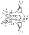
- FIG. 2A shows a rear-view of a backpack with a personal hydration system in accordance with certain embodiments of the present invention
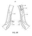
- FIG. 2B shows a front-view of the backpack of FIG. 2A in accordance with certain embodiments of the present invention
- FIG. 3A shows a side-view of a personal hydration system
- FIG. 3B shows a perspective view of a user wearing the personal hydration system of FIG.3A .
- FIG. 4 shows a perspective view of a personal hydration system worn by a user
- FIG. 5A shows a front-view of a personal hydration system
- FIG. 5B shows a front-view of a personal hydration system
- FIG. 6A shows a rear-view of a personal hydration system
- FIG. 6B shows a front-view of the personal hydration system of FIG. 6A ;
- FIG. 7A shows a rear-view of a personal hydration system
- FIG. 7B shows a front-view of the personal hydration system of FIG. 7A ;
- FIG. 7C shows a front-view of another embodiment of the personal hydration system of FIG. 7A ;
- FIG. 8A shows a rear-view of a personal hydration system
- FIG. 8B shows a front-view of the personal hydration system of FIG. 8A ;
- FIG. 9A shows an external baffle system
- FIG. 9B shows another structure of an external baffle system of FIG. 9A ;
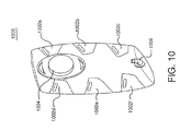
- FIG. 10 shows a hydration reservoir
- FIG. 11 shows a personal hydration system
- FIG. 12A shows a disassembled personal hydration and external baffle system
- FIG. 12B shows a partly assembled personal hydration and external baffle system of FIG. 12A .
- FIG.1 shows a personal hydration system 100 that may be employed in accord with the present invention.
- the personal hydration system 100 may comprise a baffled hydration reservoir 102, which may be referred to as the baffled bladder 102.
- the baffled bladder 102 may have a cap 108 near the top and an opening 112 near an elliptically shaped bottom 116.
- the opening 112 may be connected to a mouth piece 106 (e.g., a nozzle) through a liquid conduit 104 (e.g., a hose).
- a user may draw hydrating liquid from the baffled bladder 102 through the mouthpiece 106 during physical exercise.
- the baffled bladder 102 may contain a baffle frame 110.
- the baffle frame 110 may comprise a plurality of baffles 114a and 114b. Although in the example, two baffles are shown, any number of baffles may be used.
- the elliptically shaped bottom 116 may provide the baffled bladder with a greater capacity and a low center of gravity, thus making it suitable for holding and/or transporting a large volume of liquid.
- the baffles 114a and 114b may provide dampening structures to reduce hydration liquid movement.
- baffles 114a and 114b may be fixed to the baffle frame 110.
- the baffle frame 110 may not be needed, and the baffles 114a and 114b may be placed in different orientations (e.g., one horizontal and one vertical, both horizontal, both vertical).
- the baffles 1 14a and 1146 may be placed with angles to facilitate hydration liquid to flow to the bottom of the baffled bladder 102.
- baffles 114a and 114b may be made of porous material.
- Porosity may be a factor under consideration for slosh reduction.
- baffle porosity may be low to impede liquid movement.
- baffle porosity may be high to facilitate hydration liquid movement (e.g., to converge at the bottom of a bladder).
- the porosity of the baffle material, and the number and orientation of baffles may be combined to achieve slosh reduction.
- the baffles 114a and 114b may be made of flexible and/or pliable material, thus they may be easily removed from the baffled bladder 102 for cleaning of the baffled bladder 102 and/or baffles 114a and 114b.
- the baffle material may be also light and non-absorbing thus making more hydration liquid available to a user.
- the baffle material may also have a low freezing point. Accordingly, the baffle may be pre-refrigerated in a freezer before being put in a bladder, thus keeping hydration liquid in the bladder cool.
- the baffle may be made of metal, foam, or inflatable material.
- the baffled bladder 102 may be made of plastic or other flexible material.
- FIG. 2A and FIG. 2B show a rear-view and a front-view of a backpack 200 with a personal hydration system in accordance with certain embodiments of the present invention.
- the backpack 200 comprises a hydration reservoir compartment 202.
- the hydration reservoir compartment 202 contains a hydration reservoir (e.g., a baffled bladder as described previously in FIG. 1 ).
- the backpack 200 also comprises a pressure system which comprises a cable 220, two cable sheaths 204a and 204b, a cable housing 206, a lacing system 208 and a plurality of lacing guides 210a, 210b, 210c and 210d.
- the backpack 200 may further comprise a pair of compression wing panels 212a and 212b.
- the backpack 200 may be secured on a user's body by detachable straps 214a and 214b, which are also shown in FIG. 2B .
- the cable housing 206 is shown to terminate proximate to a cable reel 216 and the backpack 200 may also comprise two compression wing panels 218a and 218b in the front.
- the pressure system of the backpack 200 provides compression to the hydration reservoir compartment 202.
- the pressure system uses the cable 220 (e.g., a cord).
- the cable 220 may engage a steel wire lacing such as, but not limited to, the lacing system 208.
- An exemplary embodiment of a backpack 200 uses a lacing system 208 in conjunction with the backpack panels to act as a hydration compression system.
- the lacing system 208 is engaged through the cable sheaths 204a and 204b and the plurality of lacing guides 210a, 210b, 210c and 210d, the compression forces generated are applied directly upon hydration reservoir compartment 202 of the backpack 200 and through which applied upon the hydration reservoir contained therein.
- the hydration reservoir compartment 202 applies continuous pressure upon the hydration reservoir reducing liquid movement (slosh) and creating a better flow rate through the hydration reservoir and associated drinking hose and nozzle (not shown).
- the hydration reservoir compression system is disengaged, compression of the hydration reservoir compartment 202 may be relieved, allowing for removal and refilling of the hydration reservoir.
- the hydration reservoir may be a baffled bladder as described previously in reference to FIG. 1 .
- FIG. 3A and 3B show a side-view and a perspective-view of a personal hydration system 300.
- the personal hydration system 300 may comprise a hydration reservoir 302, a hose 304, a head section 306, a valve 308, a drinking hose 310 and a nozzle 312 .
- the hose 304 at one end may connect to an opening near the bottom of the hydration reservoir 302.
- the hose 304 then may run through the head section 306 before connecting to the valve 308.
- the drinking hose 310 may connect the nozzle 312 to the valve 308.
- the nozzle 312 may be a mouthpiece that a user may draw hydration liquid through.
- the head section 306 may be a hat that accommodates the hose 304 to run through an inside rim of the hat where the rim touches the head of a user.
- the hydration reservoir 302 may be a baffled bladder as described previously in reference to FIG 1 .
- the personal hydration system 300 is worn by a user.
- the hose 304 and drinking hose 310 may also be attached to minimize their movement when a user moves.
- the personal hydration system 300 may be put into a hydration reservoir compartment of a backpack (e.g., a backpack as shown in FIG 2A and 2B ).
- a backpack e.g., a backpack as shown in FIG 2A and 2B .
- hydration liquid may run through the hose 304 and the head section 306 before flowing to the drinking hose 310 and the nozzle 312. Hydration liquid may thus act as a cooling agent to cool the user's head.
- FIG. 4 shows a perspective view of a personal hydration system 400 worn by a user .
- the personal hydration system 400 may comprise a low profile reservoir 402, a mouth piece 404, a watch 406 and a sweat band 408.
- a user may use the mouth piece 404 to draw hydration liquid from the low profile reservoir 402.
- the user may use watch 406 as a sport watch.
- the sweat band 408 may also facilitate physical exercise of the user.
- the watch 406 and/or sweat band 408 may be optional.
- the personal hydration system 400 may optionally comprise a map and/or a dry erase board.
- the watch 406, sweat band 408, map and dry erase board may be part of a multifunction panel.
- FIG. 5A and 5B show a front-view and a rear-view of a personal hydration system 500 .
- the personal hydration system 500 may comprise a low profile reservoir 502 and a plurality of perforated baffles.
- the low profile reservoir 502 may wrap around a user's body.
- the combination of low profile and baffles may reduce the slosh caused by movement of hydration liquid within the low profile reservoir 502.
- the perforated baffles reduce volume in an already low profile bladder, i.e. minimized volume. Slosh is minimized since liquid has less room to move around in the small volume and square area.
- the perforated baffles reduce the overall weight of the bladder.
- FIG. 6A and 6B show a front-view and a rear-view of a personal hydration system 600 .
- the personal hydration system 600 may comprise a low profile reservoir 602.
- the low profile reservoir 602 may comprise a plurality of branches 610.
- the low profile reservoir 602 and the plurality of branches 610 may wrap around a user's body.
- the personal hydration system 600 may further comprise an opening 604 near the bottom of the low profile reservoir 602.
- the opening 604 may be connected to a drinking hose 606.
- the drinking hose 606 may be connected to a mouthpiece 608 as shown in FIG. 6B .
- the combination of low profile and plurality of branches may reduce the slosh caused by movement of hydration liquid within the low profile reservoir 602.
- the low profile reservoir 602 may be removably attached to a shirt in the fashion of a harness.
- the low profile reservoir 602 may be integrated into a shirt (e.g., built into a shirt). Further, the low profile reservoir 602 may wrap around the body to mimic the spine and/or ribs to offer a front and back system. Alternatively, the low profile reservoir 602 may wrap around the body in any pattern and with just a front or a back.
- FIG. 7A, 7B and 7C show a rear-view, two alternative front-views of a personal hydration system 700
- the personal hydration system 700 may comprise a low profile contoured lumbar reservoir 702, a drinking hose 704 and two shoulder straps 708a and 708b.
- the two shoulder straps 708a and 708b may be fluidly connected in a v-shaped joint 712.
- the v-shaped joint 712 may be further fluidly connected to the low profile contoured lumbar reservoir 702.
- the drinking hose 704 may be removably attached to the shoulder strap 708a.
- the drinking hose 704 may be removably attached to the shoulder strap 708b.
- a nozzle 706 may be connected to the drinking hose 704 as shown in FIG. 7C .
- the two shoulder straps 708a and 708b may be fixed together by two straps 710a and 710 b as shown in FIG. 7B .
- Another strap 708 may be used to fit the personal hydration system 700 to a user's body.
- the two shoulder straps 708a and 708b may be joined together (e.g., fluidly connected) in the front of the personal hydration system 700.
- the low profile v-shaped reservoir may wrap around a user's body for an improved fit for the personal hydration system 700.
- the lumbar reservoir may increase liquid capacity.
- the lumbar reservoir may contain baffles as described previously in reference to FIG. 1 . The combination of low profile and baffles may reduce the slosh caused by movement of hydration liquid.
- FIG. 8A and 8B show a rear-view and a front-view of a personal hydration system 800 .
- the personal hydration system 800 may comprise a hydration reservoir 802, a hose 806 and a clip 804.
- the hydration reservoir 802 may be in a contoured lumbar shape. The contoured lumbar shape may help the hydration reservoir to reduce slosh and forms to the body of a user.
- the hose 806 may be connected to a mouthpiece 808 as shown in FIG. 8B .
- the hose 806 may be secured to the hydration reservoir 802 by the clip 804.
- a user of the personal hydration system 800 may draw hydration liquid from the hydration reservoir 802 through the mouthpiece 808.
- the mouthpiece 808 may be attached to a shirt of the user when not in use.
- the mouthpiece 808 may be a magnetic bite valve.
- the magnetic bite valve may be mounted to a valve mount integrated into the user's shirt.
- FIG. 9A and 9B show two exemplary embodiments of a hydration reservoir compartment with external baffles 900.
- the hydration reservoir compartment 900 may comprise a back panel 902 and a front panel 908.
- a plurality of baffles 904 may be attached to the back panel 902 and the front panel 908.
- the baffles 904 may compress portions of the bladder in hydration reservoir compartment with external baffles 900.
- the combination of compression (e.g., sandwiches the bladder) and baffles may reduce the slosh caused by movement of hydration liquid.
- FIG. 9B there is shown another hydration reservoir compartment 900.
- a plurality of baffles 906 may be in different shape and arrangement in comparison to the baffles 904. Other shapes and arrangement of baffles may be used .
- FIG. 10 shows a hydration reservoir 1000.
- the hydration reservoir 1000 may comprise a cap 1004 near the top, a hose connector 1006 near the bottom and a plurality of gel pods 1002.
- the gel pods 1002a-f may serve as baffles to dampen movement of hydration liquid.
- the plurality of geld pods 1002 may be refrigerated before putting in the hydration reservoir 1000, thus they may help to keep the hydration liquid cool.
- FIG. 11 shows a personal hydration system 1100.
- the personal hydration system 1100 may comprise a hydration reservoir 1102, a cap 1104, a drinking hose 1106, and an air pump 1108.
- the cap 1104 may be located near the top of the hydration reservoir 1102.
- the drinking hose 1106 may be connected to the bottom of the hydration reservoir 1102.
- the air pump 1108 may be fluidly connected to the hydration reservoir 1102.
- a user of the personal hydration system 1100 exercises the user may draw hydration liquid through the drinking hose 1106.
- movement of the user may cause the air pump 1108 to pump air into the hydration reservoir 1102.
- the air pump is low pressure thus replacing drained liquid with air until volume of bladder is filled without over-inflation. Therefore, as hydration liquid level in the hydration reservoir 1102 may decrease, the overall volume may be kept constant, thus slosh may be reduced.
- FIGS. 12A and 12B show a personal hydration system 1200.
- the personal hydration system 1200 may comprise a frame 1202 and a hydration reservoir 1204.
- the hydration reservoir 1204 may comprise a removable cap 1206. Hydration liquid may be put in the hydration reservoir 1204 when the removable cap 1206 is removed.
- the frame 1202 may be an X-shaped frame. As shown in FIG. 12B , when assembled, the pressure created by the snaps pulling on the frame 1202 may compress the hydration reservoir 1204 externally. Further, the frame 1202 may serve as a baffle structure by pressing the hydration reservoir 1204 and protruding into the inner space of the hydration reservoir 1204, thus reducing hydration liquid movement.
Landscapes
- Professional, Industrial, Or Sporting Protective Garments (AREA)
- Portable Outdoor Equipment (AREA)
- Devices For Dispensing Beverages (AREA)
- Apparatus For Making Beverages (AREA)
- External Artificial Organs (AREA)
- Respiratory Apparatuses And Protective Means (AREA)
Description
- The present invention generally relates to personal hydration systems. More specifically, the present invention relates to apparatus and methods that control the slosh of hydration liquid in a personal hydration system as a user of the personal hydration system participates in various physical activities.
- People doing exercises, such as, bicyclists, hikers, rowers, racers, walkers, and other athletes, frequently utilize what are known as "personal hydration systems" to maintain adequate hydration while engaging in their respective activities. Other individuals may also benefit from such a hydration system, such as construction workers, etc. These personal hydration systems typically have a bag-like fluid reservoir (e.g., a bladder) that is carried in a back or waist-mounted pack. A long, flexible hose is connected to the reservoir at one end and terminates at a mouthpiece at the other end. The hose is long enough to allow the mouthpiece to be carried in the user's mouth to enable the user to draw or suck water from the reservoir at will. Valeriana, US Patent Application number
US 2006/0243765 discloses such a personal hydration system. - A personal hydration system may be subject to substantial jostling due to body movement of a user while the user is engaging in an activity (e.g., running, biking, hiking, etc.). As a result of this jostling, hydration liquid contained within a fluid reservoir of the personal hydration system is subject to forces to move about actively (e.g., slosh). Slosh of hydration liquid may exert forces on the fluid reservoir and may cause the fluid reservoir to move about actively on the user's body. Further, slosh of hydration liquid in the fluid reservoir may create unpleasant noises when the user is exercising.
- The use of baffles to create smaller areas of volume within a larger space in order to reduce liquid movement has been used in oil tankers and other large cargo ships. The lower volume and square area available for liquid movement decreases the disturbance impact from the moving liquid.
- The present invention defined in claim 1 is directed to methods and apparatus for controlling slosh (e.g., reducing slosh) in a personal hydration system. The reduction of slosh may be accomplished by forming a hydration reservoir (e.g., a bladder) comprising multiple smaller compartments. In one of many embodiments, for example, the multiple smaller compartments may be created by placing one or more baffles in the hydration reservoir. The baffles may be placed in different orientations (e.g., horizontal, vertical). Further, the baffles may be made of porous material to enhance its ability for dampening the movement of hydration liquid. Moreover, baffle material may be flexible and pliable, which may enable easier removal and replacement of the baffles. Once removed, the baffles may be easily cleaned and the interior of bladder may also be easily cleaned. In addition, baffle material may be light and non-absorbing to maximize the amount of liquid available to a user. In one particular embodiment, baffle material may have a low freezing point, thus a baffle may be pre-refrigerated before placing into a bladder. This way, the baffle may help to keep hydration liquid cool. In another exemplary embodiment, one or more baffles may be angled to promote liquid to flow to the bottom of the bladder and pool there, thus a user can draw liquid from bladder more easily.
- In some exemplary embodiments, one or more baffles may be incorporated into the design and shape of the bladder. For example, baffles may be made integral to the bladder. In another example, the bladder may be made with more than one branch and each branch may form a small compartment.
- Other methods and apparatuses may be utilized to reduce slosh as well. For example, a bladder may have a low profile. In one exemplary embodiment, the bladder may have an oval shaped profile that keeps the center of weight low.
- The invention may be embodied in numerous other systems and through numerous other methods. The following detailed description, which, when taken in conjunction with the annexed drawings, discloses examples of the invention. Other embodiments, which incorporate some or all of the features, are also possible.
- Referring to the drawings, which form a part of this disclosure:
-
FIG. 1 shows a baffled bladder for a personal hydration system that may be employed in accordance with certain embodiments of the present invention; -
FIG. 2A shows a rear-view of a backpack with a personal hydration system in accordance with certain embodiments of the present invention; -
FIG. 2B shows a front-view of the backpack ofFIG. 2A in accordance with certain embodiments of the present invention; -
FIG. 3A shows a side-view of a personal hydration system -
FIG. 3B shows a perspective view of a user wearing the personal hydration system ofFIG.3A . -
FIG. 4 shows a perspective view of a personal hydration system worn by a user ; -
FIG. 5A shows a front-view of a personal hydration system; -
FIG. 5B shows a front-view of a personal hydration system ; -
FIG. 6A shows a rear-view of a personal hydration system; -
FIG. 6B shows a front-view of the personal hydration system ofFIG. 6A ; -
FIG. 7A shows a rear-view of a personal hydration system; -
FIG. 7B shows a front-view of the personal hydration system ofFIG. 7A ; -
FIG. 7C shows a front-view of another embodiment of the personal hydration system ofFIG. 7A ; -
FIG. 8A shows a rear-view of a personal hydration system; -
FIG. 8B shows a front-view of the personal hydration system ofFIG. 8A ; -
FIG. 9A shows an external baffle system, -
FIG. 9B shows another structure of an external baffle system ofFIG. 9A ; -
FIG. 10 shows a hydration reservoir; -
FIG. 11 shows a personal hydration system; -
FIG. 12A shows a disassembled personal hydration and external baffle system ; and -
FIG. 12B shows a partly assembled personal hydration and external baffle system ofFIG. 12A . -
FIG.1 shows apersonal hydration system 100 that may be employed in accord with the present invention. Thepersonal hydration system 100 may comprise a baffledhydration reservoir 102, which may be referred to as thebaffled bladder 102. Thebaffled bladder 102 may have acap 108 near the top and anopening 112 near an elliptically shapedbottom 116. Theopening 112 may be connected to a mouth piece 106 (e.g., a nozzle) through a liquid conduit 104 (e.g., a hose). A user may draw hydrating liquid from the baffledbladder 102 through themouthpiece 106 during physical exercise. Thebaffled bladder 102 may contain abaffle frame 110. Thebaffle frame 110 may comprise a plurality ofbaffles - The elliptically shaped
bottom 116 may provide the baffled bladder with a greater capacity and a low center of gravity, thus making it suitable for holding and/or transporting a large volume of liquid. Thebaffles - In
FIG. 1 , baffles 114a and 114b may be fixed to thebaffle frame 110. In one exemplary embodiment, thebaffle frame 110 may not be needed, and thebaffles baffled bladder 102. Moreover, there may be less baffles (e.g., just one baffle), or more baffles (e.g., three baffles, four baffles), used in thebaffled bladder 102. In one exemplary embodiment, baffles 114a and 114b may be made of porous material. Porosity may be a factor under consideration for slosh reduction. For example, baffle porosity may be low to impede liquid movement. Likewise, in another example, baffle porosity may be high to facilitate hydration liquid movement (e.g., to converge at the bottom of a bladder). In one or more exemplary embodiments, the porosity of the baffle material, and the number and orientation of baffles, may be combined to achieve slosh reduction. - In some instances, the
baffles bladder 102 for cleaning of thebaffled bladder 102 and/orbaffles baffled bladder 102 may be made of plastic or other flexible material. -
FIG. 2A andFIG. 2B show a rear-view and a front-view of abackpack 200 with a personal hydration system in accordance with certain embodiments of the present invention. As shown inFIG. 2A , thebackpack 200 comprises ahydration reservoir compartment 202. Thehydration reservoir compartment 202 contains a hydration reservoir (e.g., a baffled bladder as described previously inFIG. 1 ). Thebackpack 200 also comprises a pressure system which comprises acable 220, twocable sheaths cable housing 206, alacing system 208 and a plurality of lacing guides 210a, 210b, 210c and 210d. Thebackpack 200 may further comprise a pair ofcompression wing panels backpack 200 may be secured on a user's body bydetachable straps FIG. 2B . InFIG. 2B , thecable housing 206 is shown to terminate proximate to acable reel 216 and thebackpack 200 may also comprise twocompression wing panels - The pressure system of the
backpack 200 provides compression to thehydration reservoir compartment 202. The pressure system uses the cable 220 (e.g., a cord). Thecable 220 may engage a steel wire lacing such as, but not limited to, thelacing system 208. An exemplary embodiment of abackpack 200 uses alacing system 208 in conjunction with the backpack panels to act as a hydration compression system. When thelacing system 208 is engaged through thecable sheaths hydration reservoir compartment 202 of thebackpack 200 and through which applied upon the hydration reservoir contained therein. As the hydration reservoir compression system is further engaged (e.g., by tightening the cord), thehydration reservoir compartment 202 applies continuous pressure upon the hydration reservoir reducing liquid movement (slosh) and creating a better flow rate through the hydration reservoir and associated drinking hose and nozzle (not shown). When the hydration reservoir compression system is disengaged, compression of thehydration reservoir compartment 202 may be relieved, allowing for removal and refilling of the hydration reservoir. In one exemplary embodiment in accordance with the present disclosure, the hydration reservoir may be a baffled bladder as described previously in reference toFIG. 1 . -
FIG. 3A and 3B show a side-view and a perspective-view of apersonal hydration system 300. As shown inFIG 3A , thepersonal hydration system 300 may comprise ahydration reservoir 302, ahose 304, ahead section 306, avalve 308, adrinking hose 310 and anozzle 312. Thehose 304 at one end may connect to an opening near the bottom of thehydration reservoir 302. Thehose 304 then may run through thehead section 306 before connecting to thevalve 308. Thedrinking hose 310 may connect thenozzle 312 to thevalve 308. In one or more exemplary embodiments, thenozzle 312 may be a mouthpiece that a user may draw hydration liquid through. Thehead section 306 may be a hat that accommodates thehose 304 to run through an inside rim of the hat where the rim touches the head of a user. Thehydration reservoir 302 may be a baffled bladder as described previously in reference toFIG 1 . - As shown in
FIG. 3B , thepersonal hydration system 300 is worn by a user. Thehose 304 anddrinking hose 310 may also be attached to minimize their movement when a user moves. Thepersonal hydration system 300 may be put into a hydration reservoir compartment of a backpack (e.g., a backpack as shown inFIG 2A and2B ). When a user drinks hydration liquid through thenozzle 312 as shown inFIG 3B , hydration liquid may run through thehose 304 and thehead section 306 before flowing to thedrinking hose 310 and thenozzle 312. Hydration liquid may thus act as a cooling agent to cool the user's head. -
FIG. 4 shows a perspective view of apersonal hydration system 400 worn by a user . As shown inFIG. 4 , thepersonal hydration system 400 may comprise alow profile reservoir 402, amouth piece 404, awatch 406 and asweat band 408. During a physical exercise, a user may use themouth piece 404 to draw hydration liquid from thelow profile reservoir 402. Further, the user may use watch 406 as a sport watch. Thesweat band 408 may also facilitate physical exercise of the user. Thewatch 406 and/orsweat band 408 may be optional. Moreover, thepersonal hydration system 400 may optionally comprise a map and/or a dry erase board. Thewatch 406,sweat band 408, map and dry erase board may be part of a multifunction panel. -
FIG. 5A and 5B show a front-view and a rear-view of apersonal hydration system 500 . As shown inFIG. 5A , thepersonal hydration system 500 may comprise alow profile reservoir 502 and a plurality of perforated baffles. Thelow profile reservoir 502 may wrap around a user's body. The combination of low profile and baffles may reduce the slosh caused by movement of hydration liquid within thelow profile reservoir 502. The perforated baffles reduce volume in an already low profile bladder, i.e. minimized volume. Slosh is minimized since liquid has less room to move around in the small volume and square area. Furthermore, the perforated baffles reduce the overall weight of the bladder. -
FIG. 6A and 6B show a front-view and a rear-view of apersonal hydration system 600 . As shown inFIG. 6A , thepersonal hydration system 600 may comprise alow profile reservoir 602. Thelow profile reservoir 602 may comprise a plurality ofbranches 610. Thelow profile reservoir 602 and the plurality ofbranches 610 may wrap around a user's body. Thepersonal hydration system 600 may further comprise anopening 604 near the bottom of thelow profile reservoir 602. Theopening 604 may be connected to adrinking hose 606. Thedrinking hose 606 may be connected to amouthpiece 608 as shown inFIG. 6B . The combination of low profile and plurality of branches may reduce the slosh caused by movement of hydration liquid within thelow profile reservoir 602. Thelow profile reservoir 602 may be removably attached to a shirt in the fashion of a harness. Thelow profile reservoir 602 may be integrated into a shirt (e.g., built into a shirt). Further, thelow profile reservoir 602 may wrap around the body to mimic the spine and/or ribs to offer a front and back system. Alternatively, thelow profile reservoir 602 may wrap around the body in any pattern and with just a front or a back. -
FIG. 7A, 7B and 7C show a rear-view, two alternative front-views of apersonal hydration system 700 As shown inFIG. 7A , thepersonal hydration system 700 may comprise a low profile contouredlumbar reservoir 702, adrinking hose 704 and twoshoulder straps shoulder straps joint 712. The v-shaped joint 712 may be further fluidly connected to the low profile contouredlumbar reservoir 702. Thedrinking hose 704 may be removably attached to theshoulder strap 708a. Altemalively, thedrinking hose 704 may be removably attached to theshoulder strap 708b. Anozzle 706 may be connected to thedrinking hose 704 as shown inFIG. 7C . The twoshoulder straps straps 710a and 710 b as shown inFIG. 7B . Anotherstrap 708 may be used to fit thepersonal hydration system 700 to a user's body. Alternatively, as shown inFIG. 7C , the twoshoulder straps personal hydration system 700. The low profile v-shaped reservoir may wrap around a user's body for an improved fit for thepersonal hydration system 700. Further, the lumbar reservoir may increase liquid capacity. The lumbar reservoir may contain baffles as described previously in reference toFIG. 1 . The combination of low profile and baffles may reduce the slosh caused by movement of hydration liquid. -
FIG. 8A and 8B show a rear-view and a front-view of apersonal hydration system 800 . As shown inFIG. 8A , thepersonal hydration system 800 may comprise ahydration reservoir 802, ahose 806 and aclip 804. Thehydration reservoir 802 may be in a contoured lumbar shape. The contoured lumbar shape may help the hydration reservoir to reduce slosh and forms to the body of a user. Thehose 806 may be connected to amouthpiece 808 as shown inFIG. 8B . Thehose 806 may be secured to thehydration reservoir 802 by theclip 804. A user of thepersonal hydration system 800 may draw hydration liquid from thehydration reservoir 802 through themouthpiece 808. Themouthpiece 808 may be attached to a shirt of the user when not in use. Themouthpiece 808 may be a magnetic bite valve. The magnetic bite valve may be mounted to a valve mount integrated into the user's shirt. -
FIG. 9A and 9B show two exemplary embodiments of a hydration reservoir compartment withexternal baffles 900.. As shown inFIG. 9A , thehydration reservoir compartment 900 may comprise aback panel 902 and afront panel 908. A plurality ofbaffles 904 may be attached to theback panel 902 and thefront panel 908. When theback panel 902 andfront panel 908 are sealed together with a bladder in between to form a closed system, thebaffles 904 may compress portions of the bladder in hydration reservoir compartment withexternal baffles 900. The combination of compression (e.g., sandwiches the bladder) and baffles may reduce the slosh caused by movement of hydration liquid. InFIG. 9B , there is shown anotherhydration reservoir compartment 900. A plurality ofbaffles 906 may be in different shape and arrangement in comparison to thebaffles 904. Other shapes and arrangement of baffles may be used . -
FIG. 10 shows ahydration reservoir 1000. Thehydration reservoir 1000 may comprise acap 1004 near the top, ahose connector 1006 near the bottom and a plurality of gel pods 1002. Thegel pods 1002a-f may serve as baffles to dampen movement of hydration liquid. The plurality of geld pods 1002 may be refrigerated before putting in thehydration reservoir 1000, thus they may help to keep the hydration liquid cool. -
FIG. 11 shows apersonal hydration system 1100. As shown inFIG. 11 , thepersonal hydration system 1100 may comprise ahydration reservoir 1102, acap 1104, adrinking hose 1106, and anair pump 1108. Thecap 1104 may be located near the top of thehydration reservoir 1102. Thedrinking hose 1106 may be connected to the bottom of thehydration reservoir 1102. Theair pump 1108 may be fluidly connected to thehydration reservoir 1102. When a user of thepersonal hydration system 1100 exercises, the user may draw hydration liquid through thedrinking hose 1106. At the same time, movement of the user may cause theair pump 1108 to pump air into thehydration reservoir 1102. The air pump is low pressure thus replacing drained liquid with air until volume of bladder is filled without over-inflation. Therefore, as hydration liquid level in thehydration reservoir 1102 may decrease, the overall volume may be kept constant, thus slosh may be reduced. -
FIGS. 12A and 12B show apersonal hydration system 1200. As shown inFIG. 12A , thepersonal hydration system 1200 may comprise aframe 1202 and ahydration reservoir 1204. Thehydration reservoir 1204 may comprise aremovable cap 1206. Hydration liquid may be put in thehydration reservoir 1204 when theremovable cap 1206 is removed. Theframe 1202 may be an X-shaped frame. As shown inFIG. 12B , when assembled, the pressure created by the snaps pulling on theframe 1202 may compress thehydration reservoir 1204 externally. Further, theframe 1202 may serve as a baffle structure by pressing thehydration reservoir 1204 and protruding into the inner space of thehydration reservoir 1204, thus reducing hydration liquid movement. - The examples described herein are merely illustrative, as numerous other embodiments may be implemented without departing from the scope of the present invention as defined in further attached claims. Moreover, while certain features of the invention may be shown on only certain embodiments or configurations, these features may be exchanged, added, and removed from and between the various embodiments or configurations while remaining within the scope of the invention as defined in further attached claims. Likewise, methods described and disclosed may also be performed in various sequences, with some or all of the disclosed steps being performed in a different order than described while still remaining within the scope of the present invention as defined in further attached claims.
Claims (7)
- A backpack (200) including a personal hydration system comprising:a hydration reservoir compartment (202) containing a flexible hydration reservoir 102 for containing a supply of hydrating fluid, the hydration reservoir (102) comprising a plurality of compartments, anda compression system that compresses an external surface of the flexible hydration reservoir compartment 202), the compression system further comprising:a cable (220);a cable reel (216) to tighten and loosen the cable (220); anda lacing system (208) engaged with ends of the cable (220),wherein the compression system operates to apply continuous pressure to the hydration reservoir compartment (202) by tightening the cable (220) so that the lacing system (208) is compressed, andwherein the plurality of compartments are formed by at least one baffle (114a, 114b) placed in the hydration reservoir (102) to reduce hydration fluid movement therein.
- (Currently Amended) The backpack of claim 1, wherein the at least one baffle (114a, 114b) is a gel pad, the gel pad being capable of pre-refrigerated.
- (Currently Amended) The backpack of claim 1, wherein the at least one baffle (114a, 114b) is placed horizontally in the hydration reservoir (102).
- (Currently Amended) The backpack of claim 1, wherein the at least one baffle (114a, 114b) is placed vertically in the hydration reservoir (102).
- (Currently Amended) The backpack of claim 1, wherein the at least one baffle (114a, 114b) is placed in an angle in the hydration reservoir (102), wherein the angle facilitates the hydration liquid to flow to the bottom of the hydration reservoir (102).
- (Currently Amended) The backpack of claim 1, wherein the at least one baffle (114a, 114b) is porous.
- (Currently Amended) The backpack of claim 1, wherein the lacing system (208) comprises a steel wire having a proximal and a distal end engaged with the ends of the cable (220).
Applications Claiming Priority (2)
| Application Number | Priority Date | Filing Date | Title |
|---|---|---|---|
| US12/034,726 US8020730B2 (en) | 2008-02-21 | 2008-02-21 | Slosh controlled personal hydration system |
| PCT/US2009/034717 WO2009105674A2 (en) | 2008-02-21 | 2009-02-20 | Slosh controlled personal hydration system |
Publications (3)
| Publication Number | Publication Date |
|---|---|
| EP2279150A2 EP2279150A2 (en) | 2011-02-02 |
| EP2279150A4 EP2279150A4 (en) | 2011-06-22 |
| EP2279150B1 true EP2279150B1 (en) | 2012-12-05 |
Family
ID=40986219
Family Applications (1)
| Application Number | Title | Priority Date | Filing Date |
|---|---|---|---|
| EP09712275A Not-in-force EP2279150B1 (en) | 2008-02-21 | 2009-02-20 | A slosh controlled personal hydration system |
Country Status (4)
| Country | Link |
|---|---|
| US (1) | US8020730B2 (en) |
| EP (1) | EP2279150B1 (en) |
| CN (1) | CN102015521B (en) |
| WO (1) | WO2009105674A2 (en) |
Families Citing this family (39)
| Publication number | Priority date | Publication date | Assignee | Title |
|---|---|---|---|---|
| WO2011002784A1 (en) | 2009-06-30 | 2011-01-06 | Lineweight Llc | Personal load distribution device |
| US8177097B2 (en) * | 2009-12-08 | 2012-05-15 | Camelbak Products, Llc | Personal hydration systems, dryer mechanisms for use with personal hydration systems, and methods of drying personal hydration system reservoirs |
| US20110131713A1 (en) * | 2009-12-09 | 2011-06-09 | Darosa Olavo | Hydrating baseball chest protectors |
| GB201013008D0 (en) * | 2010-08-03 | 2010-09-15 | Clark Alan | The channel flask |
| US20130214001A1 (en) * | 2010-08-11 | 2013-08-22 | Jeffrey Katz | Hydration device |
| US9624089B1 (en) | 2010-11-11 | 2017-04-18 | Arctic Innovations, Llc | Cold weather hydration systems, devices, components and methods |
| US20130119096A1 (en) * | 2011-11-14 | 2013-05-16 | Mark Edward Morgan | Personal Waistband Storage Device |
| US8887962B2 (en) * | 2011-12-09 | 2014-11-18 | Gregory Ellis Herivel | Disposable hydration pouch |
| US9149109B2 (en) | 2012-01-09 | 2015-10-06 | Rocket44 LLC | Two reservoir fluid delivery system |
| US9320406B2 (en) * | 2012-04-05 | 2016-04-26 | Impact Products, Llc | Bucketless handle |
| US20150282536A1 (en) * | 2012-11-06 | 2015-10-08 | Gk Professional | Protective body armor having a front opening |
| ES2661415T3 (en) * | 2013-06-17 | 2018-03-28 | Victor Manuel PINTO CHULVI | Portable water container |
| US10617195B2 (en) * | 2013-07-19 | 2020-04-14 | Jeremy Nathan Coleman | Articulating backpack frame |
| FR3008593B1 (en) | 2013-07-19 | 2018-09-21 | Virbac | PORTABLE FLUID DISTRIBUTION SYSTEM FOR ANIMALS. |
| USD740020S1 (en) * | 2014-05-05 | 2015-10-06 | Kahuna Kohen | Vest with integrated fluid chambers and straw |
| GB2541901B (en) * | 2015-09-02 | 2021-10-06 | Asady Baback | Portable shower |
| US10315816B2 (en) | 2015-09-29 | 2019-06-11 | Samsonite Ip Holdings S.A R.L. | Hydration reservoir |
| US10058163B2 (en) * | 2015-10-09 | 2018-08-28 | Thule, Inc. | Adjustable backpack |
| EP3402727A4 (en) | 2016-01-14 | 2019-12-04 | DGM Creations LLC | HYDRATION SLEEVE AND BLADDER AND ASSOCIATED SYSTEMS AND METHODS |
| US10010161B2 (en) | 2016-04-26 | 2018-07-03 | TLG Technologies, LLC | Personal hydration device |
| USD796903S1 (en) | 2016-06-03 | 2017-09-12 | Shock Doctor, Inc. | Hydration bladder |
| USD806476S1 (en) | 2016-06-03 | 2018-01-02 | Shock Doctor, Inc. | Hydration bladder |
| CA3031743C (en) * | 2016-06-03 | 2023-10-03 | Shock Doctor, Inc. | Hydration bladder including liquid movement-reducing features |
| US20180035788A1 (en) | 2016-07-18 | 2018-02-08 | Rainmaker Solutions, Inc. | Headset for hydration system |
| USD822952S1 (en) * | 2016-08-29 | 2018-07-17 | Dgm Creations Llc | Garment with integrated hydration system |
| PL3634355T3 (en) * | 2017-05-08 | 2024-12-02 | Cascade Designs, Inc. | Water channel for flexible container |
| CN108143080A (en) * | 2018-03-14 | 2018-06-12 | 南京际华三五二特种装备有限公司 | A kind of water bag portable knapsack |
| US11427119B2 (en) * | 2018-03-23 | 2022-08-30 | O'dochartaigh, Llc | Fuel tank-mounted beverage container for a motorcycle |
| US11712106B2 (en) * | 2018-12-07 | 2023-08-01 | Barh Life, Inc. | Ergonomic water bladder |
| US10772410B2 (en) * | 2019-01-04 | 2020-09-15 | The North Face Apparel Corp. | Cinch pack |
| US11432640B2 (en) | 2019-05-07 | 2022-09-06 | Samsonite Ip Holdings S.A R.L. | Hydration reservoir with handle |
| USD903298S1 (en) * | 2019-05-07 | 2020-12-01 | Samsonite IP Holding S.a r.l. | Hydration reservoir with a handle |
| WO2021166235A1 (en) * | 2020-02-21 | 2021-08-26 | 株式会社アシックス | Backpack |
| US12357786B2 (en) | 2020-07-08 | 2025-07-15 | Ian Mackenzie SHARP | Portable apparatus for oxygen delivery |
| USD1035823S1 (en) | 2020-10-01 | 2024-07-16 | Samsonite Ip Holdings S.A R.L. | Hydration reservoir |
| USD975432S1 (en) * | 2020-11-24 | 2023-01-17 | Frog Physics, LLC | Backpack frame |
| US20220386763A1 (en) * | 2021-06-03 | 2022-12-08 | Daniel Edward Eastland | Modular expandable carrying system |
| USD1084785S1 (en) * | 2022-09-07 | 2025-07-22 | Camelbak Products, Llc | Fluid reservoir |
| US11712096B1 (en) | 2022-11-10 | 2023-08-01 | William Christopher Rayner | Illuminated backpack assembly |
Family Cites Families (21)
| Publication number | Priority date | Publication date | Assignee | Title |
|---|---|---|---|---|
| US4248366A (en) * | 1979-05-10 | 1981-02-03 | Christiansen James S | Adjustable beverage container holder |
| US4272768A (en) * | 1980-01-21 | 1981-06-09 | Rookard Jr Johnnie P | Multi-purpose survival canteen |
| US4550848A (en) * | 1984-05-11 | 1985-11-05 | Edward Sucato | Baffle for canteens to prevent liquid splashing sounds |
| US4768674A (en) * | 1987-07-07 | 1988-09-06 | Sip Development Corporation | Baffle for fluid containers |
| US5085349A (en) * | 1990-02-08 | 1992-02-04 | Fawcett Roger R | Resilient valve and dispensing system for bicyclists |
| US5427290A (en) * | 1994-01-10 | 1995-06-27 | Ultimate Direction, Inc. | Water pouch backpack |
| JPH08214941A (en) | 1995-02-16 | 1996-08-27 | Mie Sangyo Kk | Rucksack for carrying liquid |
| US5934599A (en) * | 1997-08-22 | 1999-08-10 | Hammerslag; Gary R. | Footwear lacing system |
| US6220490B1 (en) * | 1999-02-18 | 2001-04-24 | O'hara Robert J. | Drinking vest |
| US6267390B1 (en) * | 1999-06-15 | 2001-07-31 | The Burton Corporation | Strap for a snowboard boot, binding or interface |
| US6454132B2 (en) * | 2000-02-25 | 2002-09-24 | Christopher R. Campion | Pressure-assisted liquid delivery system |
| CA2420018A1 (en) * | 2000-09-01 | 2002-03-07 | Jeff Skillern | Hydration pouch with integral thermal medium |
| US6409048B1 (en) * | 2001-05-15 | 2002-06-25 | Gregory L. Belzeski | Pressurizing device for a personal hydration system |
| US6722533B2 (en) * | 2002-02-26 | 2004-04-20 | Jeff Skillern | Hydration pouch with detachable hose |
| US7311231B2 (en) * | 2002-02-26 | 2007-12-25 | Blackhawk Industries Product Group Unlimited Llc | Disposable pouch hydration system |
| US6848472B2 (en) * | 2003-01-10 | 2005-02-01 | John A. Bambacigno | Liquid stabilizing deflector baffle |
| US20050029313A1 (en) * | 2003-05-08 | 2005-02-10 | Fiskars Brands, Inc. | Personal hydration system |
| US7014077B2 (en) * | 2003-08-13 | 2006-03-21 | Nalge Nunc International | Portable container |
| US20080029561A1 (en) * | 2006-08-01 | 2008-02-07 | Pressure Products, L.L.C. | Pressurized fluid delivery system and method |
| US7600656B2 (en) * | 2005-01-27 | 2009-10-13 | Fiskars Brands, Inc. | Personal hydration system |
| US20060243765A1 (en) * | 2005-04-27 | 2006-11-02 | Valeriana Peter V | Pressurized personal hydration system and kit |
-
2008
- 2008-02-21 US US12/034,726 patent/US8020730B2/en not_active Expired - Fee Related
-
2009
- 2009-02-20 EP EP09712275A patent/EP2279150B1/en not_active Not-in-force
- 2009-02-20 WO PCT/US2009/034717 patent/WO2009105674A2/en not_active Ceased
- 2009-02-20 CN CN2009801141413A patent/CN102015521B/en not_active Expired - Fee Related
Also Published As
| Publication number | Publication date |
|---|---|
| US20090212081A1 (en) | 2009-08-27 |
| EP2279150A4 (en) | 2011-06-22 |
| WO2009105674A2 (en) | 2009-08-27 |
| EP2279150A2 (en) | 2011-02-02 |
| CN102015521B (en) | 2013-09-25 |
| US8020730B2 (en) | 2011-09-20 |
| CN102015521A (en) | 2011-04-13 |
| WO2009105674A3 (en) | 2009-11-26 |
Similar Documents
| Publication | Publication Date | Title |
|---|---|---|
| US8020730B2 (en) | Slosh controlled personal hydration system | |
| US5975387A (en) | Bladder frame backpack | |
| US8833619B2 (en) | Backpack, such as a hydration backpack | |
| US7509692B2 (en) | Wearable personal cooling and hydration system | |
| ES2720045T3 (en) | A bathing suit | |
| US5940880A (en) | Apparatus and method for providing coolant water to the head during exercise | |
| US8540122B2 (en) | Pressurized hydration system | |
| US6325262B1 (en) | Backpack with ram air channel | |
| US20080217367A1 (en) | Fluid pack | |
| US20200309152A1 (en) | Special Personal Cooling Device Called the Breezy Belt | |
| US20060000856A1 (en) | Hydration pack | |
| US20040134955A1 (en) | Pack supporting ventilation system | |
| EP1920678A1 (en) | Hydration system | |
| US11399612B2 (en) | Apparatus for hair cooling and dehumidification | |
| US20160135573A1 (en) | Garment with integrated hydration system | |
| US20060243765A1 (en) | Pressurized personal hydration system and kit | |
| KR100949371B1 (en) | Winter jumper | |
| US20060097019A1 (en) | Water belt | |
| AU6651600A (en) | Advanced backpack system | |
| JP2018135610A (en) | Garment with cooling function | |
| US8544115B1 (en) | Materials and methods for maintaining proper body temperature | |
| JP5666185B2 (en) | rucksack | |
| JP7365739B1 (en) | cooling garment | |
| JP7330509B2 (en) | Water storage device for cooling clothes and cooling clothes using the same | |
| CN206909985U (en) | A ventilative cushion for shoulders bag |
Legal Events
| Date | Code | Title | Description |
|---|---|---|---|
| PUAI | Public reference made under article 153(3) epc to a published international application that has entered the european phase |
Free format text: ORIGINAL CODE: 0009012 |
|
| 17P | Request for examination filed |
Effective date: 20100921 |
|
| AK | Designated contracting states |
Kind code of ref document: A2 Designated state(s): AT BE BG CH CY CZ DE DK EE ES FI FR GB GR HR HU IE IS IT LI LT LU LV MC MK MT NL NO PL PT RO SE SI SK TR |
|
| AX | Request for extension of the european patent |
Extension state: AL BA RS |
|
| DAX | Request for extension of the european patent (deleted) | ||
| A4 | Supplementary search report drawn up and despatched |
Effective date: 20110520 |
|
| REG | Reference to a national code |
Ref country code: DE Ref legal event code: R079 Ref document number: 602009011707 Country of ref document: DE Free format text: PREVIOUS MAIN CLASS: B67D0005640000 Ipc: A45F0003040000 |
|
| RIC1 | Information provided on ipc code assigned before grant |
Ipc: A45F 3/04 20060101AFI20120427BHEP Ipc: A45F 3/20 20060101ALI20120427BHEP |
|
| GRAP | Despatch of communication of intention to grant a patent |
Free format text: ORIGINAL CODE: EPIDOSNIGR1 |
|
| GRAS | Grant fee paid |
Free format text: ORIGINAL CODE: EPIDOSNIGR3 |
|
| GRAA | (expected) grant |
Free format text: ORIGINAL CODE: 0009210 |
|
| RIN1 | Information on inventor provided before grant (corrected) |
Inventor name: KIM, TAE Inventor name: HADDEN, PAGE Inventor name: LIANG, EZRA Inventor name: SHIH, WINSTON |
|
| AK | Designated contracting states |
Kind code of ref document: B1 Designated state(s): AT BE BG CH CY CZ DE DK EE ES FI FR GB GR HR HU IE IS IT LI LT LU LV MC MK MT NL NO PL PT RO SE SI SK TR |
|
| REG | Reference to a national code |
Ref country code: GB Ref legal event code: FG4D |
|
| REG | Reference to a national code |
Ref country code: CH Ref legal event code: EP |
|
| REG | Reference to a national code |
Ref country code: AT Ref legal event code: REF Ref document number: 586792 Country of ref document: AT Kind code of ref document: T Effective date: 20121215 |
|
| REG | Reference to a national code |
Ref country code: IE Ref legal event code: FG4D |
|
| REG | Reference to a national code |
Ref country code: DE Ref legal event code: R096 Ref document number: 602009011707 Country of ref document: DE Effective date: 20130131 |
|
| REG | Reference to a national code |
Ref country code: AT Ref legal event code: MK05 Ref document number: 586792 Country of ref document: AT Kind code of ref document: T Effective date: 20121205 |
|
| PG25 | Lapsed in a contracting state [announced via postgrant information from national office to epo] |
Ref country code: SE Free format text: LAPSE BECAUSE OF FAILURE TO SUBMIT A TRANSLATION OF THE DESCRIPTION OR TO PAY THE FEE WITHIN THE PRESCRIBED TIME-LIMIT Effective date: 20121205 Ref country code: ES Free format text: LAPSE BECAUSE OF FAILURE TO SUBMIT A TRANSLATION OF THE DESCRIPTION OR TO PAY THE FEE WITHIN THE PRESCRIBED TIME-LIMIT Effective date: 20130316 Ref country code: FI Free format text: LAPSE BECAUSE OF FAILURE TO SUBMIT A TRANSLATION OF THE DESCRIPTION OR TO PAY THE FEE WITHIN THE PRESCRIBED TIME-LIMIT Effective date: 20121205 Ref country code: LT Free format text: LAPSE BECAUSE OF FAILURE TO SUBMIT A TRANSLATION OF THE DESCRIPTION OR TO PAY THE FEE WITHIN THE PRESCRIBED TIME-LIMIT Effective date: 20121205 Ref country code: NO Free format text: LAPSE BECAUSE OF FAILURE TO SUBMIT A TRANSLATION OF THE DESCRIPTION OR TO PAY THE FEE WITHIN THE PRESCRIBED TIME-LIMIT Effective date: 20130305 |
|
| REG | Reference to a national code |
Ref country code: NL Ref legal event code: VDEP Effective date: 20121205 |
|
| REG | Reference to a national code |
Ref country code: LT Ref legal event code: MG4D |
|
| PG25 | Lapsed in a contracting state [announced via postgrant information from national office to epo] |
Ref country code: SI Free format text: LAPSE BECAUSE OF FAILURE TO SUBMIT A TRANSLATION OF THE DESCRIPTION OR TO PAY THE FEE WITHIN THE PRESCRIBED TIME-LIMIT Effective date: 20121205 Ref country code: PL Free format text: LAPSE BECAUSE OF FAILURE TO SUBMIT A TRANSLATION OF THE DESCRIPTION OR TO PAY THE FEE WITHIN THE PRESCRIBED TIME-LIMIT Effective date: 20121205 Ref country code: LV Free format text: LAPSE BECAUSE OF FAILURE TO SUBMIT A TRANSLATION OF THE DESCRIPTION OR TO PAY THE FEE WITHIN THE PRESCRIBED TIME-LIMIT Effective date: 20121205 Ref country code: GR Free format text: LAPSE BECAUSE OF FAILURE TO SUBMIT A TRANSLATION OF THE DESCRIPTION OR TO PAY THE FEE WITHIN THE PRESCRIBED TIME-LIMIT Effective date: 20130306 |
|
| PG25 | Lapsed in a contracting state [announced via postgrant information from national office to epo] |
Ref country code: AT Free format text: LAPSE BECAUSE OF FAILURE TO SUBMIT A TRANSLATION OF THE DESCRIPTION OR TO PAY THE FEE WITHIN THE PRESCRIBED TIME-LIMIT Effective date: 20121205 |
|
| PG25 | Lapsed in a contracting state [announced via postgrant information from national office to epo] |
Ref country code: IS Free format text: LAPSE BECAUSE OF FAILURE TO SUBMIT A TRANSLATION OF THE DESCRIPTION OR TO PAY THE FEE WITHIN THE PRESCRIBED TIME-LIMIT Effective date: 20130405 Ref country code: BE Free format text: LAPSE BECAUSE OF FAILURE TO SUBMIT A TRANSLATION OF THE DESCRIPTION OR TO PAY THE FEE WITHIN THE PRESCRIBED TIME-LIMIT Effective date: 20121205 Ref country code: CZ Free format text: LAPSE BECAUSE OF FAILURE TO SUBMIT A TRANSLATION OF THE DESCRIPTION OR TO PAY THE FEE WITHIN THE PRESCRIBED TIME-LIMIT Effective date: 20121205 Ref country code: EE Free format text: LAPSE BECAUSE OF FAILURE TO SUBMIT A TRANSLATION OF THE DESCRIPTION OR TO PAY THE FEE WITHIN THE PRESCRIBED TIME-LIMIT Effective date: 20121205 Ref country code: BG Free format text: LAPSE BECAUSE OF FAILURE TO SUBMIT A TRANSLATION OF THE DESCRIPTION OR TO PAY THE FEE WITHIN THE PRESCRIBED TIME-LIMIT Effective date: 20130305 Ref country code: SK Free format text: LAPSE BECAUSE OF FAILURE TO SUBMIT A TRANSLATION OF THE DESCRIPTION OR TO PAY THE FEE WITHIN THE PRESCRIBED TIME-LIMIT Effective date: 20121205 |
|
| PG25 | Lapsed in a contracting state [announced via postgrant information from national office to epo] |
Ref country code: NL Free format text: LAPSE BECAUSE OF FAILURE TO SUBMIT A TRANSLATION OF THE DESCRIPTION OR TO PAY THE FEE WITHIN THE PRESCRIBED TIME-LIMIT Effective date: 20121205 Ref country code: RO Free format text: LAPSE BECAUSE OF FAILURE TO SUBMIT A TRANSLATION OF THE DESCRIPTION OR TO PAY THE FEE WITHIN THE PRESCRIBED TIME-LIMIT Effective date: 20121205 Ref country code: PT Free format text: LAPSE BECAUSE OF FAILURE TO SUBMIT A TRANSLATION OF THE DESCRIPTION OR TO PAY THE FEE WITHIN THE PRESCRIBED TIME-LIMIT Effective date: 20130405 |
|
| PG25 | Lapsed in a contracting state [announced via postgrant information from national office to epo] |
Ref country code: MC Free format text: LAPSE BECAUSE OF NON-PAYMENT OF DUE FEES Effective date: 20130228 |
|
| REG | Reference to a national code |
Ref country code: CH Ref legal event code: PL |
|
| PLBE | No opposition filed within time limit |
Free format text: ORIGINAL CODE: 0009261 |
|
| STAA | Information on the status of an ep patent application or granted ep patent |
Free format text: STATUS: NO OPPOSITION FILED WITHIN TIME LIMIT |
|
| PG25 | Lapsed in a contracting state [announced via postgrant information from national office to epo] |
Ref country code: LI Free format text: LAPSE BECAUSE OF NON-PAYMENT OF DUE FEES Effective date: 20130228 Ref country code: DK Free format text: LAPSE BECAUSE OF FAILURE TO SUBMIT A TRANSLATION OF THE DESCRIPTION OR TO PAY THE FEE WITHIN THE PRESCRIBED TIME-LIMIT Effective date: 20121205 Ref country code: CH Free format text: LAPSE BECAUSE OF NON-PAYMENT OF DUE FEES Effective date: 20130228 |
|
| 26N | No opposition filed |
Effective date: 20130906 |
|
| REG | Reference to a national code |
Ref country code: FR Ref legal event code: ST Effective date: 20131031 |
|
| GBPC | Gb: european patent ceased through non-payment of renewal fee |
Effective date: 20130305 |
|
| PG25 | Lapsed in a contracting state [announced via postgrant information from national office to epo] |
Ref country code: CY Free format text: LAPSE BECAUSE OF FAILURE TO SUBMIT A TRANSLATION OF THE DESCRIPTION OR TO PAY THE FEE WITHIN THE PRESCRIBED TIME-LIMIT Effective date: 20121205 |
|
| REG | Reference to a national code |
Ref country code: IE Ref legal event code: MM4A |
|
| PG25 | Lapsed in a contracting state [announced via postgrant information from national office to epo] |
Ref country code: IT Free format text: LAPSE BECAUSE OF FAILURE TO SUBMIT A TRANSLATION OF THE DESCRIPTION OR TO PAY THE FEE WITHIN THE PRESCRIBED TIME-LIMIT Effective date: 20121205 |
|
| REG | Reference to a national code |
Ref country code: DE Ref legal event code: R097 Ref document number: 602009011707 Country of ref document: DE Effective date: 20130906 |
|
| PG25 | Lapsed in a contracting state [announced via postgrant information from national office to epo] |
Ref country code: IE Free format text: LAPSE BECAUSE OF NON-PAYMENT OF DUE FEES Effective date: 20130220 Ref country code: HR Free format text: LAPSE BECAUSE OF FAILURE TO SUBMIT A TRANSLATION OF THE DESCRIPTION OR TO PAY THE FEE WITHIN THE PRESCRIBED TIME-LIMIT Effective date: 20130731 Ref country code: GB Free format text: LAPSE BECAUSE OF NON-PAYMENT OF DUE FEES Effective date: 20130305 Ref country code: FR Free format text: LAPSE BECAUSE OF NON-PAYMENT OF DUE FEES Effective date: 20130228 |
|
| PG25 | Lapsed in a contracting state [announced via postgrant information from national office to epo] |
Ref country code: MT Free format text: LAPSE BECAUSE OF FAILURE TO SUBMIT A TRANSLATION OF THE DESCRIPTION OR TO PAY THE FEE WITHIN THE PRESCRIBED TIME-LIMIT Effective date: 20121205 |
|
| PG25 | Lapsed in a contracting state [announced via postgrant information from national office to epo] |
Ref country code: TR Free format text: LAPSE BECAUSE OF FAILURE TO SUBMIT A TRANSLATION OF THE DESCRIPTION OR TO PAY THE FEE WITHIN THE PRESCRIBED TIME-LIMIT Effective date: 20121205 |
|
| PG25 | Lapsed in a contracting state [announced via postgrant information from national office to epo] |
Ref country code: MK Free format text: LAPSE BECAUSE OF FAILURE TO SUBMIT A TRANSLATION OF THE DESCRIPTION OR TO PAY THE FEE WITHIN THE PRESCRIBED TIME-LIMIT Effective date: 20121205 Ref country code: HU Free format text: LAPSE BECAUSE OF FAILURE TO SUBMIT A TRANSLATION OF THE DESCRIPTION OR TO PAY THE FEE WITHIN THE PRESCRIBED TIME-LIMIT; INVALID AB INITIO Effective date: 20090220 Ref country code: LU Free format text: LAPSE BECAUSE OF NON-PAYMENT OF DUE FEES Effective date: 20130220 |
|
| PGFP | Annual fee paid to national office [announced via postgrant information from national office to epo] |
Ref country code: DE Payment date: 20200204 Year of fee payment: 12 |
|
| REG | Reference to a national code |
Ref country code: DE Ref legal event code: R119 Ref document number: 602009011707 Country of ref document: DE |
|
| PG25 | Lapsed in a contracting state [announced via postgrant information from national office to epo] |
Ref country code: DE Free format text: LAPSE BECAUSE OF NON-PAYMENT OF DUE FEES Effective date: 20210901 |