EP2279077B1 - Tablet compressing machine and process for cleaning the sealed housing thereof - Google Patents
Tablet compressing machine and process for cleaning the sealed housing thereof Download PDFInfo
- Publication number
- EP2279077B1 EP2279077B1 EP09732977.5A EP09732977A EP2279077B1 EP 2279077 B1 EP2279077 B1 EP 2279077B1 EP 09732977 A EP09732977 A EP 09732977A EP 2279077 B1 EP2279077 B1 EP 2279077B1
- Authority
- EP
- European Patent Office
- Prior art keywords
- tablet compressing
- compressing machine
- actuator
- tablet
- rack
- Prior art date
- Legal status (The legal status is an assumption and is not a legal conclusion. Google has not performed a legal analysis and makes no representation as to the accuracy of the status listed.)
- Not-in-force
Links
- 238000004140 cleaning Methods 0.000 title claims description 26
- 238000000034 method Methods 0.000 title claims description 7
- 230000008569 process Effects 0.000 title claims description 5
- 239000007788 liquid Substances 0.000 claims description 26
- 238000005507 spraying Methods 0.000 claims description 18
- 238000009475 tablet pressing Methods 0.000 claims description 8
- 238000012544 monitoring process Methods 0.000 claims description 4
- 238000007599 discharging Methods 0.000 claims 1
- 239000000843 powder Substances 0.000 description 9
- 239000000725 suspension Substances 0.000 description 6
- 238000013461 design Methods 0.000 description 5
- 238000004519 manufacturing process Methods 0.000 description 5
- 230000005484 gravity Effects 0.000 description 4
- 230000014759 maintenance of location Effects 0.000 description 2
- 239000000463 material Substances 0.000 description 2
- 239000002184 metal Substances 0.000 description 2
- 230000000284 resting effect Effects 0.000 description 2
- 230000006978 adaptation Effects 0.000 description 1
- 230000004075 alteration Effects 0.000 description 1
- 230000005540 biological transmission Effects 0.000 description 1
- 238000010276 construction Methods 0.000 description 1
- 230000008878 coupling Effects 0.000 description 1
- 238000010168 coupling process Methods 0.000 description 1
- 238000005859 coupling reaction Methods 0.000 description 1
- 230000007547 defect Effects 0.000 description 1
- 230000001419 dependent effect Effects 0.000 description 1
- 238000001514 detection method Methods 0.000 description 1
- 238000011010 flushing procedure Methods 0.000 description 1
- 230000007246 mechanism Effects 0.000 description 1
- 239000003595 mist Substances 0.000 description 1
- 238000012986 modification Methods 0.000 description 1
- 230000004048 modification Effects 0.000 description 1
- 238000012806 monitoring device Methods 0.000 description 1
- 239000002245 particle Substances 0.000 description 1
- 239000004033 plastic Substances 0.000 description 1
- 238000009420 retrofitting Methods 0.000 description 1
- 239000007921 spray Substances 0.000 description 1
- 239000000126 substance Substances 0.000 description 1
- 230000000576 supplementary effect Effects 0.000 description 1
- 238000012546 transfer Methods 0.000 description 1
- 238000005406 washing Methods 0.000 description 1
- XLYOFNOQVPJJNP-UHFFFAOYSA-N water Substances O XLYOFNOQVPJJNP-UHFFFAOYSA-N 0.000 description 1
Images


Classifications
-
- B—PERFORMING OPERATIONS; TRANSPORTING
- B30—PRESSES
- B30B—PRESSES IN GENERAL
- B30B11/00—Presses specially adapted for forming shaped articles from material in particulate or plastic state, e.g. briquetting presses, tabletting presses
- B30B11/02—Presses specially adapted for forming shaped articles from material in particulate or plastic state, e.g. briquetting presses, tabletting presses using a ram exerting pressure on the material in a moulding space
- B30B11/08—Presses specially adapted for forming shaped articles from material in particulate or plastic state, e.g. briquetting presses, tabletting presses using a ram exerting pressure on the material in a moulding space co-operating with moulds carried by a turntable
-
- B—PERFORMING OPERATIONS; TRANSPORTING
- B08—CLEANING
- B08B—CLEANING IN GENERAL; PREVENTION OF FOULING IN GENERAL
- B08B9/00—Cleaning hollow articles by methods or apparatus specially adapted thereto
-
- B—PERFORMING OPERATIONS; TRANSPORTING
- B08—CLEANING
- B08B—CLEANING IN GENERAL; PREVENTION OF FOULING IN GENERAL
- B08B9/00—Cleaning hollow articles by methods or apparatus specially adapted thereto
- B08B9/08—Cleaning containers, e.g. tanks
- B08B9/0821—Handling or manipulating containers, e.g. moving or rotating containers in cleaning devices, conveying to or from cleaning devices
- B08B9/0826—Handling or manipulating containers, e.g. moving or rotating containers in cleaning devices, conveying to or from cleaning devices the containers being brought to the cleaning device
-
- B—PERFORMING OPERATIONS; TRANSPORTING
- B08—CLEANING
- B08B—CLEANING IN GENERAL; PREVENTION OF FOULING IN GENERAL
- B08B9/00—Cleaning hollow articles by methods or apparatus specially adapted thereto
- B08B9/08—Cleaning containers, e.g. tanks
- B08B9/093—Cleaning containers, e.g. tanks by the force of jets or sprays
-
- B—PERFORMING OPERATIONS; TRANSPORTING
- B30—PRESSES
- B30B—PRESSES IN GENERAL
- B30B15/00—Details of, or accessories for, presses; Auxiliary measures in connection with pressing
- B30B15/0082—Dust eliminating means; Mould or press ram cleaning means
Definitions
- the invention relates to a tablet compressing machine with a sealed housing in which a rotor unit and a spraying apparatus are disposed, whereby the spraying apparatus is provided for spraying a cleaning liquid into the sealed housing.
- Such a tablet compressing machine is known from the document DE 20 2007 003 176 U1 .
- the document DE 20 2007 003 176 U1 describes a tablet compressing machine, in which a cleaning liquid can be distributed, submerging the rotor and wherein ultra-sonic waves can be applied in the sealed housing to cleanse particles off from surfaces.
- Another tablet compressing machine is known from the document EP 0 637 507 A1 .
- the document EP 0 637 507 A1 describes a method of washing a tablet compressing machine, wherein in a first step a cleaning liquid is distributed. In a second step, a flushing liquid is distributed and the liquid sucked out of the housing.
- JP-A-62 097799 discloses a tablet compressing machine according to the preamble of claim 1 with a sealed housing, in which a rotor unit and a spraying apparatus are disposed. It also discloses a method in accordance with the preamble of claim 14. The spraying apparatus is provided for distributing a cleaning liquid in the sealed housing.
- Generic tablet compressing machines normally have a rotor unit comprising a die plate, an upper stamp holder and a lower stamp holder.
- the die plate is provided with a plurality of bores for inserting the upper or lower stamp during rotation.
- the upper and the lower stamps compress powdery material into shaped tablets.
- the upper and lower stamps are movably arranged in axial direction in associated upper and lower stamp holders. After the tablet has been compressed within a bore in the die plate, it is normally pushed out of the corresponding bore of the die plate by the lower stamps.
- the combination of upper stamps and holders, die plate and lower stamps and holders is called a rotor unit.
- Generic tablet compressing machines have a capacity of 500 to 25 000 tablets per minute depending upon the number of upper and lower stamps and the speed with which the rotor rotates.
- the cleaning liquid together with the bound powder residues forms puddles on horizontal surfaces which do not drain away. These surfaces may, for instance, be formed on the rotor unit, on ancillary units and parts of the housing. Usually the rotor unit and the spraying facility are at least partially disposed within the sealed housing so that no powder components can pass into the surrounding area during tablet production.
- the invention is aimed at reducing the work and effort involved in constructing and manufacturing a tablet compressing machine.
- an actuator for a tablet compressing machine with a sealed housing in which a rotor unit and a spraying apparatus are disposed.
- the actuator is arranged to at least tilt the sealed housing by a tilting angle ⁇ cleanse .
- the actuator provides for tilting at least the sealed housing by a tilting angle ⁇ cleanse , so that the cleaning liquid can drain off.
- the actuator may be arranged so as to tilt the entire tablet compressing machine or only part of it, namely the sealed housing.
- Existing tablet compressing machines may be fitted with an actuator so that they can be tilted.
- a sealed housing does not necessarily have to be a hermetically sealed area, all that is is required is that powder cannot penetrate into the surrounding area of the tablet compressing machine.
- a draining channel is provided through which the cleaning liquid may be discharged.
- at least one draining channel is provided which is located on that side within the sealed housing, towards which the sealed housing is tilted.
- the draining channel may be a narrow elongated channel or a simple bore, an active suction device or similar. In the operating position of the tablet compressing machine, namely in the state, in which tablets are produced, the sealed housing is not tilted by the acuator.
- the area surrounding the sealed housing is the area, in which the powder is processed into tablets. This is the area which is required to be cleaned.
- the cleaning liquid cannot form any puddles on horizontal surfaces and can thus drain off.
- the rack may, for example, be a tubular grid frame and/or a plate frame. It should preferably be constructed in such a way as to support the heavy rotor unit.
- the rack may incorporate a spindle, a bearing or a drive for the rotor unit.
- the rack may comprise the entire tablet compressing machine or may be part of a further rack.
- the actuator used to tilt the tablet compressing machine is a translationally extending actuator, i.e. a linear drive.
- the rack enclosing the sealed housing is tilted by means of the actuator.
- the rack may be a part of the tablet compressing machine or comprise the entire tablet compressing machine.
- the actuator thus preferably moves in a translational direction and thereby lifts the rack, preferably the entire tablet compressing machine partially, whereby this machine is tilted.
- the actuator may be a mass-produced product. It may be an electric motor with a mechanical or hydraulic transmission attached to it, an hydraulic or pneumatic cylinder or a pneumatic lifting pad. This type of actuator is particularly well suited for equipping existing tablet compressing machines with the tilting mechanism of the present invention.
- the sealed housing and the rotor unit In the tablet compressing machine according to the invention it is possible for the sealed housing and the rotor unit to have horizontal surfaces when in operating position. In the prior art, these horizontal surfaces machines did not allow the cleaning liquid to drain away. With the tablet compressing machine according to the invention which is equipped with an actuator it is not necessary to take into consideration how a liquid can drain away, thereby the work and effort involved in constructing and manufacturing the machine is reduced. Commonly used production processes are simplified by providing right-angled relations between two surfaces, this particularly applies to cylindrical components and housings, leading to cost savings. It goes without saying that not all floors of the tablet compressing machine must be horizontal when in operation position. It is also feasible that at least one of the floors in the sealed housing is inclined to one side. In this case the tilting of the tablet compressing machine has a supplementary effect in draining away the cleaning liquid.
- the rack in which the rotor unit and the sealed housing are disposed, rests on dampening and suspension elements such as rubber bearings.
- dampening and suspension elements such as rubber bearings.
- rubber bearings dampen and suspend the transfer of solid-borne sound between the tablet compressing machine and the floor on which the tablet compressing machine stands.
- the actuator in the operating position, that is in the position in which the tablets are produced, shall preferably be retracted in such a way that there is mechanical decoupling between the rack and the floor and the tablet compressing machine or between the tablet pressing machine and the floor so that the rack or the tablet pressing machine is only resting on the rubber bearings.
- the actuator itself has dampening and suspension properties and is not lifted off the floor plate in operating position of the tablet compressing machine, but continues to support the weight of the tablet compressing machine.
- Hydraulic and pneumatic cylinders for example, have dampening and suspension properties which are dependent upon their piston diameter and their stroke. Their dampening and suspension characteristics may therefore be adjusted via these parameters in a way known to those skilled in the art, in order to meet the dampening and suspension requirements of a heavy tablet compressing machine. If an electro-mechanical actuator is utilised, additional dampening and suspension means may be provided if necessary.
- the rubber bearings are shaped in such a way as to enable the tilting of the tablet compressing machine. It is not mandatory to provide several rubber bearings, there could also be one single-piece rubber bearing or an elongated rail arranged on the floor surface.
- the rubber bearings on the side to be lifted or the area of the rubber bearings which are lifted are preferably equipped with means which enable the tablet compressing machine to be returned safely to its original position. For instance, positive guiding into the operating position may be realised by one or several locking pins.
- the actuator is adapted to at least tilt the sealed housing by a tilting angle ⁇ cleanse , which typically varies between 1.5 and 4°.
- the tilting angle ⁇ cleanse is selected in such a way that the tablet compressing machine is safely prevented from falling over, in general it will be smaller than 20°.
- the deciding factor is that the actuator is configured in such a way that it tilts the horizontal surfaces enclosed in the sealed housing when the tablet compressing machine is at a standstill, for example during and/or immediately after cleaning.
- the actuator must not be allowed to extend to the extent where the centre of gravity of the tablet compressing machine, in tilting direction, reaches a point behind an axis about which the tablet compressing machine rotates during tilting.
- the centre of gravity of the tablet compressing machine is found at a comparatively high level since the rotor unit usually comprises many heavy components and is situated in the upper half of the machine.
- the person skilled in the art may roughly calculate the tilting angle ⁇ max , at which the tablet compressing machine is in danger of falling over, by assuming that the centre of gravity is at the very top in the middle, for example.
- the limiting means may be a positively locking end stop beyond which tilting is not possibe.
- the stroke of the actuator may be limited mechanically or electronically. Combinations of the mentioned limiting means are also possible.
- tablet compressing machines are usually relatively heavy, powerful actuators are required for lifting the tablet compressing machine, and these would be able to tilt the tablet compressing machine beyond the maximum tilting angle ⁇ max , which must be prevented to stop the tablet pressing machine from falling over.
- a mechanical limitation on the tablet compressing machine for example a clamp, which interacts between a floor plate and the rack, the tilting angle is limited to a maximum tilting angle ⁇ max1 and the risk of it falling over is eliminated.
- the actuator is provided with a mechanical end stop inherent in the design; on a cylinder these could be, for example, the cylinder faces beyond which the piston cannot be extended. But since the actuator does not have to be a custom made actuator but a mass-produced one, the end stop may be subsequently fitted to the actuator.
- a clamp for example, may be attached to a first actuator portion which extends relative to a second actuator portion, whereby the clamp limits the relative extension path, resulting in a further maximum tilting angle ⁇ max2 .
- the tablet compressing machine is provided with a limit stop which switches the actuator off when a maximum defined angle ⁇ max3 is reached. This is advantageous for actuators having a relatively long extension path.
- the limit stop prevents the tablet compressing machine from falling over in case of it being wrongly operated.
- the limit stop may be adjustable, for example by a switch which is acted upon by a corresponding piece until operation of the switch stops or vice versa.
- the corresponding piece is adjustable, allowing ⁇ max3 to be adapted according to the circumstances.
- the tablet compressing machine is equipped with a device for monitoring the tilting angle ⁇ tilt .
- This monitoring device may be used to control the actuator. It is also feasible that the actuator is slowed down prior to reaching the tilting angle ⁇ cleanse set by the operator so that when the desired tilting angle ⁇ cleanse is reached the machine stops without jerking. If a device for monitoring the tilting angle ⁇ tilt is used, a maximum tilting angle ⁇ max4 , at which falling over of the tablet compressing machine is safely avoided, can be implemented in a simple manner even without mechanical alterations to the tablet compressing machine.
- angles ⁇ max1 , ⁇ max2 , ⁇ max3 and ⁇ max4 may be calculated according to the angle ⁇ max in the manner described above, they may also be equal.
- the rubber bearings below the tablet compressing machine dampen and cushion the vibrations occurring in the tablet compressing machine when it is in operating position. If the actuator acts to tilt the entire tablet compressing machine, it can lift the tablet compressing machine in such a way that at least one but possibly also two or more rubber bearings loose contact with the floor. The rubber bearings which remain in contact now bear the weight of the machine together with the actuator.
- mechanical means are provided on the tablet compressing machine by means of which the supporting rubber bearings are prevented from becoming detached when the tablet compressing machine is tilted.
- a projection on the rack which projection is provided on a first locking element, may engage in a recess of a second locking portion arranged on the floor plate so that the detaching movement of the rack relative to the floor plate is limited.
- the mechanical means may serve to define the rotating axis of the tilting movement of the sealed housing.
- the locking elements ensure that when the tablet compressing machine is lifted from above for positioning it, the floor plate is also lifted.
- the retrofit should comprise only a minimum of modifications. It is up to the person skilled in the art to decide, whether it is necessary to install the above described locking elements on a tablet compressing machine to be retrofitted as per the invention, so that tilting can be implemented, or whether the design of the tablet compressing machine is sufficient to allow safe tilting without the above described locking elements. If the person skilled in the art decides to install the locking elements, the first locking elements may be attached, for example, on the rack of the tablet compressing machine and the second locking elements may be attached on the floor or on a floor plate. In principle, when retrofitting an existing tablet compressing machine to produce a tablet compressing machine according to the invention, an actuator is installed which acts between the floor of a floor plate and the tablet compressing machine or its rack.
- the rack of the tablet compressing machine may be decoupled from the floor plate in such a way that the tablet compressing machine only rests on the rubber bearings.
- the actuator may retract in such a way that when the tablet compressing machine is in operating position, it does not lead to any mechanical coupling between the floor plate and the rack.
- FIG 1 a side view of a tablet compressing machine with a sealed housing 11 comprising a spraying apparatus 21 and a rotor unit 20 is shown.
- the rotor unit 20 is mounted in a bearing 27 and connected with a drive 25 via a rotor spindle 23.
- the arrangement of the sealed housing 11, the rotor unit 20, the spraying apparatus 21, the rotor spindle 23, the drive 25 and the bearing 27 is arranged on a rack 10 which provides stability.
- the rack 10 is suitable for supporting the above mentioned elements and/or for mounting them and may be a tubular grid frame or an arrangement of metal sheets.
- the spraying apparaturs 21 is designed to distribute a cleaning liquid within the sealed housing 11. After the spraying apparatus 21 has distributed a cleaning liquid within the sealed housing 11, the cleaning liquid drains into a draining channel 22. According to the invention draining of the cleaning liquid into the draining channel 22 is supported by the actuator 3 tilting the rack with the sealed housing 11 including the rotor unit 20 arranged thereon at least partially and the spraying apparatus 21 towards the draining channel 22.
- the rack 10 in which the sealed housing is arranged, rests on at least one rubber bearing 9.
- the rubber bearing 9 is designed to dampen the vibrations occurring during operation of the tablet compressing machine 1.
- the tablet compressing machine is illustrated in figure 1 as a side view, resting on four bearings.
- the tablet compressing machine 1 has a floor plate 8. This is pivotably linked with the rack 10 via at least one rubber bearing 9, illustrated on the right. While the tablet pressing machine 1 is in use and it is not tilted, the rack 10 also rests on at least one further rubber bearing 9, as illustrated on the left.
- the rack 10 also has a base plate 4 on which a first locking element 12 is arranged which is designed to engage in a recess on a second locking element 13.
- the second locking element 13 is arranged on the floor plate 8.
- the locking elements 12, 13 serve to prevent the rubber elements 9 from becoming detached when the tablet compressing machine 1 is tilted.
- locking elements 12, 13 define the rotating axis of the tilting movement of rack 10 in relation to the floor plate 8 and ensure that the tablet compressing machine 1 can be lifted in one piece from above without the floor plate 8 falling off or being connected by actuator 3 to the rack 10 only.
- the actuator 3 is adapted to act upon a base 7 which is preferably pivotably linked with the actuator.
- the base 7 is enclosed within a holding-down element 5.
- the holding-down element 5 is mechanically connected with the floor plate 8, for instance by means of a screw.
- the end of the actuator 3 is further connected to the rack 10.
- the holding-down element 5 may be arranged on the rack 10 and the actuator 3 may be connected with the floor plate 8.
- the base 7 is meant to be an element, by means of which actuator 3 may exert a force upon the floor plate 8. Therefore, the base 7 is mechanically linked to the actor and has a substantially flat contact surface.
- the base 7 is pivotably linked with one end of a first actuator portion 17, in order to compensate the changeable angle relationships between floor plate 8 and actuator longitudinal axis during tilting.
- a floor plate 8 is understood to be an element on which the tablet compressing machine 1 stands. It need not have the shape of a plate but may be a grid frame or similar. If the room in which the tablet compressing machine 1 is installed, is provided with a machine bed, the floor plate 8 may be this machine bed. The deciding factor is that the actuator 3 can be supported between the tablet compressing machine 1, for example its rack 10, and the floor plate 8.
- a retention clamp 37 is, for example, arranged on the floor plate 8 - which grips the base plate 4 of rack 10 with a certain amount of clearance.
- the retention clamp acts as a mechanical stop.
- Limiting the tilting angle to ⁇ manx2 and ⁇ max3 is the subject of the description with reference to figures 3 and 5 , respectively.
- ⁇ max2 is limited by a mechanical limitation of the extension path of actuator 3 and that ⁇ max3 is limited by an electronic limit stop of actuator 3.
- a tilting angle detection unit 31 is schematically shown for measuring the tilting angle ⁇ tilt .
- the actuator 3 may have its own control so that the tablet compressing machine 1 is automatically tilted at a preprogrammed tilting angle ⁇ cleanse .
- the actuator 3 could move as a result of the operation of a push button, whereby a corresponding push button is not necessarily arranged on the tablet compressing machine.
- the tilting angle ⁇ tilt reaches a tilting angle ⁇ maxa4 , at which angle there is a risk of the tablet compressing machine falling over, the actuator 3 is stopped, even although the operator continues to hold the push button down.
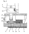
- Figure 2 shows the area designated 50 in figure 1 in greater detail.
- the actuator 3 acts with a first actuator portion 17 upon the floor plate 8 via the base 7.
- a force is created within the actuator 3 in the known manner, that is hydraulically, pneumatically or electro-hydraulically, between the first actuator portion 17 and a second actuator portion 18 which is suitable to lift one side of the tablet compressing machine 1 in order to tilt it.
- an electro-mechanical drive may be a spindle drive.
- the tablet compressing machine 1 is in operating position in which the base 7 does not contact of the floor plate 8. This is necessary for NVH reasons, since otherwise the actuator 3 could transmit vibrations from the tablet compressing machine 1 to the floor plate 8.
- contact elements 15 are arranged below the floor plate 8, which are preferably manufactured from plastic or rubber. These may comprise compressed air connections (not shown) on their underside so that when the tablet compressing machine 1 is acted upon by compressed air, it hovers on an air cushion and may be moved easily.
- the holding down element 5 is connected to the floor plate 8 so that movement of the base 7 in the holding-down element 5 is limited in vertical direction.
- a switch 35 and a corresponding piece 34 are schematically shown. These two elements can be used to make up a limit stop.
- a switch 35 ist connected to the floor plate 8, whilst the corresponding piece 34 is connected to the base plate 4.
- the switch is operated when the maximum tilting angle ⁇ max3 is reached, thereby closing or opening an electrical contact, creating a signal which stops the actuator.
- at least one of the switch 35 and the corresponding piece 34 are formed in such a way that adaptation of the tilting angle ⁇ max3 , at which the limit stop is operated, can be performed easily.
- the limit stop is operated, the actuator 3 is stopped thereby preventing the tablet compressing machine 1 from falling over.
- Figur 3 shows the area 50 of figure 1 , in which the actuator 3 is shown as being partially operated , i.e. the actuator portion 17 is shown in an extended position.
- the tablet compressing machine 1- is tilted by the angle ⁇ tilt , the base 7 touches the floor plate 8.
- a locking pin 6 which is preferably attached to the rubber element 9. This ensures in combination with a recess in floor plate 5 (not shown), that the rubber element 9 always comes to rest in the same place, when the tablet compressing machine 1 is tilted back into the operating position, that is when the tablet compressing machine 1 is returned safely into its original position.
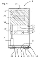
- a rack 10' is arranged in a frame 36 in the embodiment shown in figure 4 .
- the frame 36 may be a tubular grid frame.
- the rack 10' is defined in the same way as the above described rack 10, as an element which is suitable for supporting the rotor unit 20 mounted in a bearing 27 and connected via a rotor spindle 27 to a drive 25.
- the combination of the sealed housing 11, the rotor unit 20, the spraying apparatus 21, the rotor spindle 23, the drive 25 and the bearing 27 is arranged on or in the rack 10', which ensures mechanical stability.
- the rack 10' may be a tubular grid frame or a combination of metal sheets.
- the rack 10' is housed inside frame 36 in such a way that it can be tilted in direction of frame 36 when the actuator 3 is operated.
- the frame 36 is designed in such a way as to be able to support the rack 10'.
- the frame 36 is stationary and is not tilted. Instead of tilting the entire tablet compressing machine 1, only rack 10' is tilted towards frame 36, i.e. only a part of the tablet compressing machine 1 is tilted.
- the actuator 3 is effective between base plate 4 and rack 10'.
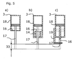
- FIG 5 three examples representing a possible end stop 16 of actuator 3 are shown.
- An end stop 16 is provided to prevent the tablet compressing machine 1 from falling over in case of misoperation or defect.
- the tilting angle ⁇ tilt is limited to a maximum tilting angle ⁇ max2 .
- the actuator 3 is depicted as a hydraulic cylinder because it simplifies the illustration of an end stop 16.
- the variants in the embodiments can also be equipped without problems with an electro-mechanical drive with a spindle or a toothed rack.
- the broken lines are representative of the positions of the first actuator portion 17 when it reaches the end stop 16.
- the actuator 3 is advantageously limited in its extension path 33.
- An extension path 33 of this length is not mandatory, so that limiting the extension path to 10 cm should be sufficient as a rule.
- FIG 5 b an alternative design of an end stop 16 is shown.
- the extension path 33 may be limited by a sleeve 14 which prevents the first actuator portion 17 from extending any further when the extension path 33 is reached.
- Figure 5 c) shows a similar design, here the extension path 33 of the actuator 3 is limited by means of a clamp 19.
Landscapes
- Engineering & Computer Science (AREA)
- Mechanical Engineering (AREA)
- Medical Preparation Storing Or Oral Administration Devices (AREA)
- Presses And Accessory Devices Thereof (AREA)
- Cleaning By Liquid Or Steam (AREA)
Description
- This application claims priority to German Application no.
DE 10 2008 019 272, filed April 16, 2008 and German Application No.DE 10 2008 046 670, filed September 10, 2008 , the contents of which are expressly incorporated by reference in their entirety as part of the present disclosure. - The invention relates to a tablet compressing machine with a sealed housing in which a rotor unit and a spraying apparatus are disposed, whereby the spraying apparatus is provided for spraying a cleaning liquid into the sealed housing.
- Such a tablet compressing machine is known from the
document DE 20 2007 003 176 U1 . Thedocument DE 20 2007 003 176 U1 describes a tablet compressing machine, in which a cleaning liquid can be distributed, submerging the rotor and wherein ultra-sonic waves can be applied in the sealed housing to cleanse particles off from surfaces. Another tablet compressing machine is known from the documentEP 0 637 507 A1 . The documentEP 0 637 507 A1 describes a method of washing a tablet compressing machine, wherein in a first step a cleaning liquid is distributed. In a second step, a flushing liquid is distributed and the liquid sucked out of the housing. In a third step, all openings of the housing are closed and a vacuum is applied to dry the sealed housing quickly. Finally documentJP-A-62 097799 claim 1 with a sealed housing, in which a rotor unit and a spraying apparatus are disposed. It also discloses a method in accordance with the preamble ofclaim 14. The spraying apparatus is provided for distributing a cleaning liquid in the sealed housing. - Generic tablet compressing machines normally have a rotor unit comprising a die plate, an upper stamp holder and a lower stamp holder. The die plate is provided with a plurality of bores for inserting the upper or lower stamp during rotation. Thereby the upper and the lower stamps compress powdery material into shaped tablets. The upper and lower stamps are movably arranged in axial direction in associated upper and lower stamp holders. After the tablet has been compressed within a bore in the die plate, it is normally pushed out of the corresponding bore of the die plate by the lower stamps. The combination of upper stamps and holders, die plate and lower stamps and holders is called a rotor unit. Generic tablet compressing machines have a capacity of 500 to 25 000 tablets per minute depending upon the number of upper and lower stamps and the speed with which the rotor rotates.
- When changing to another batch, that is when the powdery material is changed, for introducing a new powder which is to be compressed, the previous powder must first be completely removed from the machine. No residues of the previous powder should get into the surrounding air, which is why the rotor units in tablet compressing machines are normally encapsulated in a sealed housing. Generic tablet compressing machines are usually equipped with a spraying apparatus by means of which a cleaning liquid such as water may be distributed for removing the residual medical substance. Powder components suspended in air are captured by the spray mist and bound by the liquid, whereupon they sink down and settle on horizontal surfaces of the rotor unit and its vicinity. Powder residues already laying on surfaces are bound in the same way. The cleaning liquid together with the bound powder residues forms puddles on horizontal surfaces which do not drain away. These surfaces may, for instance, be formed on the rotor unit, on ancillary units and parts of the housing. Usually the rotor unit and the spraying facility are at least partially disposed within the sealed housing so that no powder components can pass into the surrounding area during tablet production.
- In order to drain the cleaning liquid off the tablet compressing machine it is known in the prior art to provide only inclined, that is non-horizontal surfaces within the tablet compressing machine, thus avoiding the forming of puddles. However, a lot of effort is required to provide only non-horizontal surfaces in such a complicated machine as a tablet compressing machine, in particular when a plurality of components are involved.
- This is the state of the prior art on which the invention is based. The invention is aimed at reducing the work and effort involved in constructing and manufacturing a tablet compressing machine.
- The requirement is met by a tablet compressing machine according to
patent claim 1, by a process for cleaning a sealed housing of a tablet compressing machine according topatent claim 14. - It is proposed to provide an actuator for a tablet compressing machine with a sealed housing in which a rotor unit and a spraying apparatus are disposed. The actuator is arranged to at least tilt the sealed housing by a tilting angle αcleanse.
- The actuator provides for tilting at least the sealed housing by a tilting angle αcleanse, so that the cleaning liquid can drain off. The actuator may be arranged so as to tilt the entire tablet compressing machine or only part of it, namely the sealed housing. Existing tablet compressing machines may be fitted with an actuator so that they can be tilted.
- A sealed housing does not necessarily have to be a hermetically sealed area, all that is is required is that powder cannot penetrate into the surrounding area of the tablet compressing machine.
- According to an advantageous further embodiment of the invention a draining channel is provided through which the cleaning liquid may be discharged. Preferably at least one draining channel is provided which is located on that side within the sealed housing, towards which the sealed housing is tilted. The draining channel may be a narrow elongated channel or a simple bore, an active suction device or similar. In the operating position of the tablet compressing machine, namely in the state, in which tablets are produced, the sealed housing is not tilted by the acuator.
- The area surrounding the sealed housing is the area, in which the powder is processed into tablets. This is the area which is required to be cleaned. By tilting the sealed housing possibly including the rotor unit to that side on which a draining channel is located, the cleaning liquid cannot form any puddles on horizontal surfaces and can thus drain off. At least the rotor unit, the spraying apparatus and the sealed housing are at least partially arranged on a rack of the tablet compressing machine. The rack may, for example, be a tubular grid frame and/or a plate frame. It should preferably be constructed in such a way as to support the heavy rotor unit. Furthermore the rack may incorporate a spindle, a bearing or a drive for the rotor unit. The rack may comprise the entire tablet compressing machine or may be part of a further rack.
- Preferably the actuator used to tilt the tablet compressing machine is a translationally extending actuator, i.e. a linear drive. In order to allow the cleaning liquid to drain off, the rack enclosing the sealed housing is tilted by means of the actuator. The rack may be a part of the tablet compressing machine or comprise the entire tablet compressing machine. The actuator thus preferably moves in a translational direction and thereby lifts the rack, preferably the entire tablet compressing machine partially, whereby this machine is tilted.
- The actuator may be a mass-produced product. It may be an electric motor with a mechanical or hydraulic transmission attached to it, an hydraulic or pneumatic cylinder or a pneumatic lifting pad. This type of actuator is particularly well suited for equipping existing tablet compressing machines with the tilting mechanism of the present invention.
- In the tablet compressing machine according to the invention it is possible for the sealed housing and the rotor unit to have horizontal surfaces when in operating position. In the prior art, these horizontal surfaces machines did not allow the cleaning liquid to drain away. With the tablet compressing machine according to the invention which is equipped with an actuator it is not necessary to take into consideration how a liquid can drain away, thereby the work and effort involved in constructing and manufacturing the machine is reduced. Commonly used production processes are simplified by providing right-angled relations between two surfaces, this particularly applies to cylindrical components and housings, leading to cost savings. It goes without saying that not all floors of the tablet compressing machine must be horizontal when in operation position. It is also feasible that at least one of the floors in the sealed housing is inclined to one side. In this case the tilting of the tablet compressing machine has a supplementary effect in draining away the cleaning liquid.
- According to an advantageous further embodiment of the invention the rack, in which the rotor unit and the sealed housing are disposed, rests on dampening and suspension elements such as rubber bearings. During the tablet compressing process, rubber bearings dampen and suspend the transfer of solid-borne sound between the tablet compressing machine and the floor on which the tablet compressing machine stands. In this embodiment, in the operating position, that is in the position in which the tablets are produced, the actuator shall preferably be retracted in such a way that there is mechanical decoupling between the rack and the floor and the tablet compressing machine or between the tablet pressing machine and the floor so that the rack or the tablet pressing machine is only resting on the rubber bearings.
- Alternatively, according to an advantageous further embodiment of the invention, the actuator itself has dampening and suspension properties and is not lifted off the floor plate in operating position of the tablet compressing machine, but continues to support the weight of the tablet compressing machine. Hydraulic and pneumatic cylinders, for example, have dampening and suspension properties which are dependent upon their piston diameter and their stroke. Their dampening and suspension characteristics may therefore be adjusted via these parameters in a way known to those skilled in the art, in order to meet the dampening and suspension requirements of a heavy tablet compressing machine. If an electro-mechanical actuator is utilised, additional dampening and suspension means may be provided if necessary.
- When tilting the tablet compressing machine, preferably one corner or side of the tablet compressing machine is lifted. According to another preferred embodyment of the invention, the rubber bearings are shaped in such a way as to enable the tilting of the tablet compressing machine. It is not mandatory to provide several rubber bearings, there could also be one single-piece rubber bearing or an elongated rail arranged on the floor surface. The rubber bearings on the side to be lifted or the area of the rubber bearings which are lifted are preferably equipped with means which enable the tablet compressing machine to be returned safely to its original position. For instance, positive guiding into the operating position may be realised by one or several locking pins.
- According to an advantageous further embodiment of the invention the actuator is adapted to at least tilt the sealed housing by a tilting angle αcleanse, which typically varies between 1.5 and 4°. The tilting angle αcleanse is selected in such a way that the tablet compressing machine is safely prevented from falling over, in general it will be smaller than 20°. According to the invention it is immaterial whether the entire rack including the rotor unit, the spraying apparatus and the sealed housing is tilted or whether only the seated housing together with the rotor unit is tilted. The deciding factor is that the actuator is configured in such a way that it tilts the horizontal surfaces enclosed in the sealed housing when the tablet compressing machine is at a standstill, for example during and/or immediately after cleaning.
- For safety reasons it is advisable to provide safeguards to prevent the tablet compressing machine from falling over by means of a limiting means. The actuator must not be allowed to extend to the extent where the centre of gravity of the tablet compressing machine, in tilting direction, reaches a point behind an axis about which the tablet compressing machine rotates during tilting. The centre of gravity of the tablet compressing machine is found at a comparatively high level since the rotor unit usually comprises many heavy components and is situated in the upper half of the machine. The person skilled in the art may roughly calculate the tilting angle αmax, at which the tablet compressing machine is in danger of falling over, by assuming that the centre of gravity is at the very top in the middle, for example. In the tilting direction, this point must not protrude beyond the axis about which tilting occurs. The limiting means may be a positively locking end stop beyond which tilting is not possibe. Alternatively the stroke of the actuator may be limited mechanically or electronically. Combinations of the mentioned limiting means are also possible.
- Since tablet compressing machines are usually relatively heavy, powerful actuators are required for lifting the tablet compressing machine, and these would be able to tilt the tablet compressing machine beyond the maximum tilting angle αmax, which must be prevented to stop the tablet pressing machine from falling over. By providing a mechanical limitation on the tablet compressing machine, for example a clamp, which interacts between a floor plate and the rack, the tilting angle is limited to a maximum tilting angle αmax1 and the risk of it falling over is eliminated.
- According to an advantageous embodiment of the invention, the actuator is provided with a mechanical end stop inherent in the design; on a cylinder these could be, for example, the cylinder faces beyond which the piston cannot be extended. But since the actuator does not have to be a custom made actuator but a mass-produced one, the end stop may be subsequently fitted to the actuator. A clamp, for example, may be attached to a first actuator portion which extends relative to a second actuator portion, whereby the clamp limits the relative extension path, resulting in a further maximum tilting angle αmax2.
- According to an advantageous embodiment of the invention the tablet compressing machine is provided with a limit stop which switches the actuator off when a maximum defined angle αmax3 is reached. This is advantageous for actuators having a relatively long extension path. The limit stop prevents the tablet compressing machine from falling over in case of it being wrongly operated.
- In addition the limit stop may be adjustable, for example by a switch which is acted upon by a corresponding piece until operation of the switch stops or vice versa. Preferably, the corresponding piece is adjustable, allowing αmax3 to be adapted according to the circumstances.
- According to a further advantageous embodiment of the invention the tablet compressing machine is equipped with a device for monitoring the tilting angle αtilt. This monitoring device may be used to control the actuator. It is also feasible that the actuator is slowed down prior to reaching the tilting angle αcleanse set by the operator so that when the desired tilting angle αcleanse is reached the machine stops without jerking. If a device for monitoring the tilting angle αtilt is used, a maximum tilting angle αmax4, at which falling over of the tablet compressing machine is safely avoided, can be implemented in a simple manner even without mechanical alterations to the tablet compressing machine.
- The angles αmax1, αmax2, αmax3 and αmax4 may be calculated according to the angle αmax in the manner described above, they may also be equal.
- It is also feasible to combine the electronic device for monitoring the tilting angle with a mechanical end stop and a mechanical limit stop of the actuator in the tablet compressing machine. The safety is increased by this measure, but it is left to the person skilled in the art, which means he uses to prevent falling over of the tablet compressing machine.
- The rubber bearings below the tablet compressing machine dampen and cushion the vibrations occurring in the tablet compressing machine when it is in operating position. If the actuator acts to tilt the entire tablet compressing machine, it can lift the tablet compressing machine in such a way that at least one but possibly also two or more rubber bearings loose contact with the floor. The rubber bearings which remain in contact now bear the weight of the machine together with the actuator.
- According to an advantageous further embodiment of the invention mechanical means are provided on the tablet compressing machine by means of which the supporting rubber bearings are prevented from becoming detached when the tablet compressing machine is tilted. For example, a projection on the rack, which projection is provided on a first locking element, may engage in a recess of a second locking portion arranged on the floor plate so that the detaching movement of the rack relative to the floor plate is limited. This is advantageous because the main load of the tablet compressing machine during tilting continues to act, at least partially, on a rubber block arranged next to the locking arrangement, which deforms during a tilting movement and may become detached. In addition the mechanical means may serve to define the rotating axis of the tilting movement of the sealed housing. Furthermore the locking elements ensure that when the tablet compressing machine is lifted from above for positioning it, the floor plate is also lifted.
- In order to be able to equip existing tablet compressing machines with the tilting apparatus according to the invention, the retrofit should comprise only a minimum of modifications. It is up to the person skilled in the art to decide, whether it is necessary to install the above described locking elements on a tablet compressing machine to be retrofitted as per the invention, so that tilting can be implemented, or whether the design of the tablet compressing machine is sufficient to allow safe tilting without the above described locking elements. If the person skilled in the art decides to install the locking elements, the first locking elements may be attached, for example, on the rack of the tablet compressing machine and the second locking elements may be attached on the floor or on a floor plate. In principle, when retrofitting an existing tablet compressing machine to produce a tablet compressing machine according to the invention, an actuator is installed which acts between the floor of a floor plate and the tablet compressing machine or its rack.
- It is advantageous for the rack of the tablet compressing machine to be decoupled from the floor plate in such a way that the tablet compressing machine only rests on the rubber bearings. To this end the actuator may retract in such a way that when the tablet compressing machine is in operating position, it does not lead to any mechanical coupling between the floor plate and the rack.
- Further advantages of the invention are revealed in the described embodiments with reference to the figures, in which
- Fig. 1:
- shows a side view of a tablet compressing machine according to the invention with an actuator,
- Fig. 2:
- shows an enlarged section of
figure 1 , - Fig. 3:
- shows the section of
figure 2 , the difference being that a part of the tablet pressing machine has been tilted, - Fig. 4:
- shows a further tablet compressing machine according to the invention in which only parts of the tablet pressing machine can be tilted, and
- Fig. 5
- shows three variants of an actuator with a mechanical end stop.
- In
figure 1 a side view of a tablet compressing machine with a sealedhousing 11 comprising aspraying apparatus 21 and arotor unit 20 is shown. Therotor unit 20 is mounted in abearing 27 and connected with adrive 25 via arotor spindle 23. The arrangement of the sealedhousing 11, therotor unit 20, the sprayingapparatus 21, therotor spindle 23, thedrive 25 and thebearing 27 is arranged on arack 10 which provides stability. Therack 10 is suitable for supporting the above mentioned elements and/or for mounting them and may be a tubular grid frame or an arrangement of metal sheets. - The spraying
apparaturs 21 is designed to distribute a cleaning liquid within the sealedhousing 11. After thespraying apparatus 21 has distributed a cleaning liquid within the sealedhousing 11, the cleaning liquid drains into a drainingchannel 22. According to the invention draining of the cleaning liquid into the drainingchannel 22 is supported by theactuator 3 tilting the rack with the sealedhousing 11 including therotor unit 20 arranged thereon at least partially and the sprayingapparatus 21 towards the drainingchannel 22. - During production of the tablets which is performed within the
rotor unit 20 and which is not described here in further detail, therack 10, in which the sealed housing is arranged, rests on at least onerubber bearing 9. Therubber bearing 9 is designed to dampen the vibrations occurring during operation of thetablet compressing machine 1. The tablet compressing machine is illustrated infigure 1 as a side view, resting on four bearings. - Also with reference to
figure 1 thetablet compressing machine 1 has afloor plate 8. This is pivotably linked with therack 10 via at least onerubber bearing 9, illustrated on the right. While thetablet pressing machine 1 is in use and it is not tilted, therack 10 also rests on at least onefurther rubber bearing 9, as illustrated on the left. Therack 10 also has abase plate 4 on which afirst locking element 12 is arranged which is designed to engage in a recess on asecond locking element 13. Thesecond locking element 13 is arranged on thefloor plate 8. The lockingelements rubber elements 9 from becoming detached when thetablet compressing machine 1 is tilted. In addition the lockingelements rack 10 in relation to thefloor plate 8 and ensure that thetablet compressing machine 1 can be lifted in one piece from above without thefloor plate 8 falling off or being connected byactuator 3 to therack 10 only. - The
actuator 3 is adapted to act upon abase 7 which is preferably pivotably linked with the actuator. Thebase 7 is enclosed within a holding-downelement 5. The holding-downelement 5 is mechanically connected with thefloor plate 8, for instance by means of a screw. According to the variant shown, the end of theactuator 3 is further connected to therack 10. If the person skilled in the art chooses another variant, in which theactuator 3 is connected to thefloor plate 8 without a clearance, the holding-downelement 5 may be arranged on therack 10 and theactuator 3 may be connected with thefloor plate 8. In this case, thebase 7 is meant to be an element, by means of which actuator 3 may exert a force upon thefloor plate 8. Therefore, thebase 7 is mechanically linked to the actor and has a substantially flat contact surface. Preferably, thebase 7 is pivotably linked with one end of afirst actuator portion 17, in order to compensate the changeable angle relationships betweenfloor plate 8 and actuator longitudinal axis during tilting. - In principle, a
floor plate 8 is understood to be an element on which thetablet compressing machine 1 stands. It need not have the shape of a plate but may be a grid frame or similar. If the room in which thetablet compressing machine 1 is installed, is provided with a machine bed, thefloor plate 8 may be this machine bed. The deciding factor is that theactuator 3 can be supported between thetablet compressing machine 1, for example itsrack 10, and thefloor plate 8. - In
figure 1 aretention clamp 37 is, for example, arranged on thefloor plate 8- which grips thebase plate 4 ofrack 10 with a certain amount of clearance. When the tilting angle αtilt reaches a maximum tilting angle αmax1, the retention clamp acts as a mechanical stop. Limiting the tilting angle to αmanx2 and αmax3 is the subject of the description with reference tofigures 3 and5 , respectively. At this point it should only be mentioned that αmax2 is limited by a mechanical limitation of the extension path ofactuator 3 and that αmax3 is limited by an electronic limit stop ofactuator 3. The angles αmxi, (i= 1; 2; 3; 4) do not have to be equal, rather the deciding factor is that thetablet compressing machine 1 is not tilted any further once one of the angles has been reached. - With further reference to
figure 1 a tiltingangle detection unit 31 is schematically shown for measuring the tilting angle αtilt. Theactuator 3 may have its own control so that thetablet compressing machine 1 is automatically tilted at a preprogrammed tilting angle αcleanse. Alternatively theactuator 3 could move as a result of the operation of a push button, whereby a corresponding push button is not necessarily arranged on the tablet compressing machine. When the tilting angle αtilt reaches a tilting angle αmaxa4, at which angle there is a risk of the tablet compressing machine falling over, theactuator 3 is stopped, even although the operator continues to hold the push button down. -
Figure 2 shows the area designated 50 infigure 1 in greater detail. Theactuator 3 acts with afirst actuator portion 17 upon thefloor plate 8 via thebase 7. To this end a force is created within theactuator 3 in the known manner, that is hydraulically, pneumatically or electro-hydraulically, between thefirst actuator portion 17 and asecond actuator portion 18 which is suitable to lift one side of thetablet compressing machine 1 in order to tilt it. The construction of an hydraulic or pneumatic cylinder is known and does not require explanation, an electro-mechanical drive may be a spindle drive. - In
figure 2 , thetablet compressing machine 1 is in operating position in which thebase 7 does not contact of thefloor plate 8. This is necessary for NVH reasons, since otherwise theactuator 3 could transmit vibrations from thetablet compressing machine 1 to thefloor plate 8. - Preferably contact
elements 15 are arranged below thefloor plate 8, which are preferably manufactured from plastic or rubber. These may comprise compressed air connections (not shown) on their underside so that when thetablet compressing machine 1 is acted upon by compressed air, it hovers on an air cushion and may be moved easily. - Preferably the holding down
element 5 is connected to thefloor plate 8 so that movement of thebase 7 in the holding-downelement 5 is limited in vertical direction. Furthermore aswitch 35 and acorresponding piece 34 are schematically shown. These two elements can be used to make up a limit stop. Aswitch 35 ist connected to thefloor plate 8, whilst the correspondingpiece 34 is connected to thebase plate 4. When theactuator 3 tilts therack 10 of thetablet compressing machine 1, the switch is operated when the maximum tilting angle αmax3 is reached, thereby closing or opening an electrical contact, creating a signal which stops the actuator. Preferably at least one of theswitch 35 and thecorresponding piece 34 are formed in such a way that adaptation of the tilting angle αmax3, at which the limit stop is operated, can be performed easily. When the limit stop is operated, theactuator 3 is stopped thereby preventing thetablet compressing machine 1 from falling over. -
Figur 3area 50 offigure 1 , in which theactuator 3 is shown as being partially operated , i.e. theactuator portion 17 is shown in an extended position. The tablet compressing machine 1- is tilted by the angle αtilt, thebase 7 touches thefloor plate 8. - In this view of a tilted
tablet compressing machine 1, the reader can see alocking pin 6 which is preferably attached to therubber element 9. This ensures in combination with a recess in floor plate 5 (not shown), that therubber element 9 always comes to rest in the same place, when thetablet compressing machine 1 is tilted back into the operating position, that is when thetablet compressing machine 1 is returned safely into its original position. - In contrast to
figure 1 , a rack 10' is arranged in aframe 36 in the embodiment shown infigure 4 . Theframe 36 may be a tubular grid frame. The rack 10' is defined in the same way as the above describedrack 10, as an element which is suitable for supporting therotor unit 20 mounted in abearing 27 and connected via arotor spindle 27 to adrive 25. The combination of the sealedhousing 11, therotor unit 20, the sprayingapparatus 21, therotor spindle 23, thedrive 25 and thebearing 27 is arranged on or in the rack 10', which ensures mechanical stability. The rack 10' may be a tubular grid frame or a combination of metal sheets. The rack 10' is housed insideframe 36 in such a way that it can be tilted in direction offrame 36 when theactuator 3 is operated. Theframe 36 is designed in such a way as to be able to support the rack 10'. Theframe 36 is stationary and is not tilted. Instead of tilting the entiretablet compressing machine 1, only rack 10' is tilted towardsframe 36, i.e. only a part of thetablet compressing machine 1 is tilted. In the embodiment shown infigure 4 , theactuator 3 is effective betweenbase plate 4 and rack 10'. - With reference to
figure 5 , three examples representing a possible end stop 16 ofactuator 3 are shown. Anend stop 16 is provided to prevent thetablet compressing machine 1 from falling over in case of misoperation or defect. The tilting angle αtilt is limited to a maximum tilting angle αmax2. It is advantageous to use a mass-produced linear drive to act as anactuator 3 which is not necessarily equipped with a stop inherent in the design. Here theactuator 3 is depicted as a hydraulic cylinder because it simplifies the illustration of anend stop 16. The variants in the embodiments, however, can also be equipped without problems with an electro-mechanical drive with a spindle or a toothed rack. - The broken lines are representative of the positions of the
first actuator portion 17 when it reaches theend stop 16. Theactuator 3 is advantageously limited in itsextension path 33. For example, for a 2 m high, 1 m deep and 1 m widetablet compressing machine 1 anextension path 33 of less than 5 cm is sufficient in order to realise a tilting angle of α = 3°. If the centre of gravity is unfavourable and therubber bearings 9 or lockingelements tablet compressing machine 1 could be in danger of falling over at only 12°, and therefore theextension path 33 ofactuator 3 should not be larger than 20 cm. Anextension path 33 of this length is not mandatory, so that limiting the extension path to 10 cm should be sufficient as a rule. - In
figure 5 a) an element of thefirst actuator portion 17 is stopped when it reaches theend stop 16 within thesecond actuator portion 18. Where a hydraulic orpneumatic actuator 3 is used, the piston in this case abuts against the cylinder wall. - In
figure 5 b) an alternative design of anend stop 16 is shown. Here theextension path 33 may be limited by asleeve 14 which prevents thefirst actuator portion 17 from extending any further when theextension path 33 is reached. -
Figure 5 c) shows a similar design, here theextension path 33 of theactuator 3 is limited by means of aclamp 19. - A person skilled in the art will, however, has many other prior art mechanical limiting means at his disposal.
Claims (15)
- Tablet compressing machine (1) with a sealed housing (11), in which a rotor unit (20) and a spraying apparatus (21) are disposed, whereby the spraying apparatus is provided for distributing a cleaning liquid in the sealed housing (11),
characterised in that- the tablet compressing machine (1) comprises an actuator (3) which is adapted to at least tilt the sealed housing (11) by a tilting angle αtilt. - Tablet compressing machine (1) according to claim 1, characterised in that at least one draining channel (22) for receiving the cleaning liquid is provided inside the sealed housing (11).
- Tablet compressing machine (1) according to claim 1, characterised in that the tablet compressing machine (1) further comprises a floor plate (8) and a rack (10), whereby the sealed housing (11) is mounted on the rack (10) or is part of the rack (10) and whereby the actuator (3) is adapted to operate between the floor plate (8) and the rack (10).
- Tablet compressing machine (1) according to claim 3, characterised in that the rack (10), in the operating position of the tablet compressing machine (1), rests on at least one rubber bearing (9) arranged at least partially between the rack (10) and the floor plate (8), whereby the rubber bearing (9) and/or its type of mounting are adapted to permit tilting.
- Tablet compressing machine (1) according to claim 3, characterised in that the frame (10), in operating position of the tablet compressing machine (1), rests on at least one rubber bearing (9) and the actuator (3), whereby the rubber bearing (9) is disposed at least partially between the rack (10) and the floor plate (8) and/or its type of mounting is adapted to permit tilting, and whereby the actuator (3) has dampening characteristics.
- Tablet compressing machine (1) according to claim 1, characterised in that the tilting angle αtilt is a maximum of 20°, preferably between 1.5 and 3°.
- Tablet compressing machine (1) according to claim 1, characterised in that the tilting angle αtilt is limited by mechanical limiting means to a maximum tilting angle αmax2.
- Tablet compressing machine (1) according to claim 7, characterised in that the limit stop becomes effective when it reaches an inherent end stop (16) of the actuator (3).
- Tablet compressing machine (1) according to claim 1, characterised in that the tablet compressing machine (1) further comprises a limit-switching stop, which is adapted to switch the actuator (3) off, when a maximum tilting angle of αmax3 is reached.
- Tablet compressing machine (1) according to claim 1, characterised in that the actuator (3) further comprises a facility for monitoring the extension path.
- Tablet compressing machine (1) according to claim 1, characterised in that the actuator (3) is configured to extend translationally for tilting the tablet pressing machine (1).
- Tablet compressing machine (1) according to claim 11, characterised in that the actuator (3) may be configured as an electro-mechanical, hydraulic or pneumatic linear drive.
- Tablet compressing machine (1) according to claim 1, characterised in that the actuator (3) is formed as a cushion, which is suitable to extend in at least one direction, when it is acted upon by pressure.
- Process for cleaning a sealed housing (11) of a tablet compressing machine (1) according to claim 1 comprising the following steps:a) distributing a cleaning liquid within the sealed housing (11),b) discharging the cleaning liquid
characterised in thatc) in order to discharge the cleaning liquid at least the sealed-housing (11), preferably the entire tablet compressing machine (1), is tilted by a tilting angle αtilt. - Process according to claim 14, characterised in the use of an actuator (3) for tilting the sealed housing (11) or the entire tablet pressing machine (1).
Priority Applications (1)
| Application Number | Priority Date | Filing Date | Title |
|---|---|---|---|
| PL09732977T PL2279077T3 (en) | 2008-04-16 | 2009-04-07 | Tablet compressing machine and process for cleaning the sealed housing thereof |
Applications Claiming Priority (3)
| Application Number | Priority Date | Filing Date | Title |
|---|---|---|---|
| DE102008019272 | 2008-04-16 | ||
| DE102008046670A DE102008046670B4 (en) | 2008-04-16 | 2008-09-10 | Tablet press machine |
| PCT/EP2009/054122 WO2009127557A2 (en) | 2008-04-16 | 2009-04-07 | Tablet compressing machine |
Publications (2)
| Publication Number | Publication Date |
|---|---|
| EP2279077A2 EP2279077A2 (en) | 2011-02-02 |
| EP2279077B1 true EP2279077B1 (en) | 2013-10-23 |
Family
ID=41078782
Family Applications (1)
| Application Number | Title | Priority Date | Filing Date |
|---|---|---|---|
| EP09732977.5A Not-in-force EP2279077B1 (en) | 2008-04-16 | 2009-04-07 | Tablet compressing machine and process for cleaning the sealed housing thereof |
Country Status (8)
| Country | Link |
|---|---|
| US (1) | US8435357B2 (en) |
| EP (1) | EP2279077B1 (en) |
| CN (1) | CN102046364B (en) |
| DE (1) | DE102008046670B4 (en) |
| DK (1) | DK2279077T3 (en) |
| ES (1) | ES2443549T3 (en) |
| PL (1) | PL2279077T3 (en) |
| WO (1) | WO2009127557A2 (en) |
Families Citing this family (4)
| Publication number | Priority date | Publication date | Assignee | Title |
|---|---|---|---|---|
| DE102008046670B4 (en) | 2008-04-16 | 2012-05-24 | Bwi Plc | Tablet press machine |
| CN107498727B (en) * | 2017-08-16 | 2019-06-21 | 扬州绿宝人造草坪有限公司 | A kind of the PBT composite environmental-friendly material processing unit (plant) and preparation method of light wear-resistant |
| DE102023116934B4 (en) | 2023-06-27 | 2025-12-24 | Fette Compacting Gmbh | Rotary press and method for pre-cleaning the press housing of a rotary press |
| CN121424737B (en) * | 2025-12-24 | 2026-08-07 | 天津梅花生物医药科技有限公司 | Medicine particle tabletting and forming press and tabletting manufacturing process thereof |
Family Cites Families (15)
| Publication number | Priority date | Publication date | Assignee | Title |
|---|---|---|---|---|
| US3345683A (en) * | 1964-10-23 | 1967-10-10 | Eirich Wilhelm | Inclined-dish granulator and separator |
| US3419147A (en) * | 1966-07-18 | 1968-12-31 | Crown By Products Co | Apparatus for removing grease from cans and drums |
| US3392688A (en) * | 1966-11-04 | 1968-07-16 | Korsch Spezialfab Emil | Tablet press |
| JPS59218300A (en) * | 1983-05-26 | 1984-12-08 | Hata Tekkosho:Kk | Washing method of rotary plate for rotary powder molding machine |
| US4518335A (en) * | 1984-03-14 | 1985-05-21 | Allied Corporation | Dilatant mold and dilatant molding apparatus |
| JPS6297799A (en) | 1985-10-24 | 1987-05-07 | Hata Tekkosho:Kk | Cleaning method for rotary type power compression molding machine |
| JPH03147804A (en) * | 1989-11-06 | 1991-06-24 | Toto Ltd | Method and device of pressure slip casting |
| US5032071A (en) * | 1990-03-01 | 1991-07-16 | Nabisco Brands, Inc. | Material sensing assembly in a rotary press |
| DE4326239C2 (en) * | 1993-07-31 | 1997-06-05 | Korsch Pressen Gmbh | Tableting, coating or granulating machine, in particular rotary tablet press |
| EP0823324A1 (en) * | 1996-08-09 | 1998-02-11 | Courtoy | Rotary tablet press |
| ITBO20010141A1 (en) * | 2001-03-16 | 2002-09-16 | Ima Spa | COMPRESSING MACHINE FOR THE PRODUCTION OF TABLETS |
| US7404707B2 (en) * | 2001-04-23 | 2008-07-29 | Leco Corporation | Sample mounting press |
| ES2280396T3 (en) * | 2001-09-05 | 2007-09-16 | Courtoy N.V. | PRESS OF ROTARY TABLETS AND PROCEDURE FOR CLEANING THE SUCH PRESS. |
| DE202007003176U1 (en) * | 2007-03-01 | 2007-10-18 | Ima Kilian Gmbh & Co.Kg | Rotary tablet press with washing device |
| DE102008046670B4 (en) | 2008-04-16 | 2012-05-24 | Bwi Plc | Tablet press machine |
-
2008
- 2008-09-10 DE DE102008046670A patent/DE102008046670B4/en not_active Expired - Fee Related
-
2009
- 2009-04-07 DK DK09732977.5T patent/DK2279077T3/en active
- 2009-04-07 EP EP09732977.5A patent/EP2279077B1/en not_active Not-in-force
- 2009-04-07 ES ES09732977.5T patent/ES2443549T3/en active Active
- 2009-04-07 PL PL09732977T patent/PL2279077T3/en unknown
- 2009-04-07 WO PCT/EP2009/054122 patent/WO2009127557A2/en not_active Ceased
- 2009-04-07 CN CN200980118464.XA patent/CN102046364B/en not_active Expired - Fee Related
-
2011
- 2011-06-09 US US13/156,743 patent/US8435357B2/en not_active Expired - Fee Related
Also Published As
| Publication number | Publication date |
|---|---|
| US20120141623A1 (en) | 2012-06-07 |
| DK2279077T3 (en) | 2014-02-03 |
| US8435357B2 (en) | 2013-05-07 |
| WO2009127557A2 (en) | 2009-10-22 |
| DE102008046670A1 (en) | 2009-10-22 |
| WO2009127557A3 (en) | 2010-10-21 |
| ES2443549T3 (en) | 2014-02-19 |
| CN102046364A (en) | 2011-05-04 |
| CN102046364B (en) | 2016-09-07 |
| PL2279077T3 (en) | 2014-04-30 |
| DE102008046670B4 (en) | 2012-05-24 |
| EP2279077A2 (en) | 2011-02-02 |
Similar Documents
| Publication | Publication Date | Title |
|---|---|---|
| US8435357B2 (en) | Tablet compressing machine | |
| CN108704996B (en) | Multi-station tablet feeding device and stamping production line | |
| US9585509B2 (en) | Cooking appliance | |
| CN106926321A (en) | An integrated equipment for wood sizing, high-precision cutting and waste recycling | |
| US20260043705A1 (en) | Weighing mechanism for vertical dynamic balancing machine | |
| KR101728982B1 (en) | Lift apparatus of bag for rice polishing machine | |
| KR101426883B1 (en) | Apparatus for holding material for multi axis position | |
| KR200441210Y1 (en) | apparatus for cutting plate shaped plastic foam | |
| HK1158576A (en) | Tablet compressing machine | |
| HK1158576B (en) | Tablet compressing machine | |
| CN210587390U (en) | Cutting device is used in metal product processing | |
| EP4194122A1 (en) | Blanking press and method of cleaning a half-mould | |
| CN220428272U (en) | Processing platform for mold processing | |
| JP7069323B2 (en) | Adjustable preload rail for rotary press with integrated preload measurement function | |
| JP2019042750A (en) | Powder molding press apparatus and powder molding press system | |
| CN114641390B (en) | Squeeze roller table for a rotary tablet press with external bearing support for a squeeze roller unit | |
| KR101910771B1 (en) | fixing chuck | |
| KR101456535B1 (en) | The locking equipment for slider of press system and braking method using the same | |
| JP2992529B1 (en) | Rotary powder compression molding machine | |
| CN113234919A (en) | Piston quenching device and lifting induction assembly thereof | |
| CN115533661B (en) | Notebook computer pivot processingequipment | |
| KR200180506Y1 (en) | Telescoping correcting apparatus for coil products | |
| KR101008044B1 (en) | Lubricant treatment device for preventing deterioration of roll bearing part | |
| CN223669760U (en) | Building block cleaning device | |
| CN218706388U (en) | Material conveying machine for degreasing agent |
Legal Events
| Date | Code | Title | Description |
|---|---|---|---|
| PUAI | Public reference made under article 153(3) epc to a published international application that has entered the european phase |
Free format text: ORIGINAL CODE: 0009012 |
|
| AK | Designated contracting states |
Kind code of ref document: A2 Designated state(s): AT BE BG CH CY CZ DE DK EE ES FI FR GB GR HR HU IE IS IT LI LT LU LV MC MK MT NL NO PL PT RO SE SI SK TR |
|
| AX | Request for extension of the european patent |
Extension state: AL BA RS |
|
| RBV | Designated contracting states (corrected) |
Designated state(s): AT BE BG CH CY CZ DE DK EE ES FI FR GB GR HR HU IE IS IT LI LT LU LV MC MK MT NL NO PL PT RO SE SI SK TR |
|
| 17P | Request for examination filed |
Effective date: 20110616 |
|
| DAX | Request for extension of the european patent (deleted) | ||
| RAP1 | Party data changed (applicant data changed or rights of an application transferred) |
Owner name: BWI PLC |
|
| REG | Reference to a national code |
Ref country code: DE Ref legal event code: R079 Ref document number: 602009019622 Country of ref document: DE Free format text: PREVIOUS MAIN CLASS: B30B0015000000 Ipc: B08B0009000000 |
|
| GRAP | Despatch of communication of intention to grant a patent |
Free format text: ORIGINAL CODE: EPIDOSNIGR1 |
|
| RIC1 | Information provided on ipc code assigned before grant |
Ipc: B08B 9/093 20060101ALI20130319BHEP Ipc: B08B 9/08 20060101ALI20130319BHEP Ipc: B08B 9/00 20060101AFI20130319BHEP Ipc: B30B 15/00 20060101ALI20130319BHEP Ipc: B30B 11/08 20060101ALI20130319BHEP |
|
| INTG | Intention to grant announced |
Effective date: 20130419 |
|
| RAP1 | Party data changed (applicant data changed or rights of an application transferred) |
Owner name: BOSCH PACKAGING TECHNOLOGY LIMITED |
|
| GRAS | Grant fee paid |
Free format text: ORIGINAL CODE: EPIDOSNIGR3 |
|
| GRAA | (expected) grant |
Free format text: ORIGINAL CODE: 0009210 |
|
| RAP1 | Party data changed (applicant data changed or rights of an application transferred) |
Owner name: BOSCH PACKAGING TECHNOLOGY LIMITED |
|
| AK | Designated contracting states |
Kind code of ref document: B1 Designated state(s): AT BE BG CH CY CZ DE DK EE ES FI FR GB GR HR HU IE IS IT LI LT LU LV MC MK MT NL NO PL PT RO SE SI SK TR |
|
| REG | Reference to a national code |
Ref country code: GB Ref legal event code: FG4D |
|
| REG | Reference to a national code |
Ref country code: CH Ref legal event code: EP |
|
| REG | Reference to a national code |
Ref country code: AT Ref legal event code: REF Ref document number: 637249 Country of ref document: AT Kind code of ref document: T Effective date: 20131115 |
|
| REG | Reference to a national code |
Ref country code: IE Ref legal event code: FG4D |
|
| REG | Reference to a national code |
Ref country code: DE Ref legal event code: R096 Ref document number: 602009019622 Country of ref document: DE Effective date: 20131219 |
|
| REG | Reference to a national code |
Ref country code: CH Ref legal event code: NV Representative=s name: MARKS AND CLERK (LUXEMBOURG) LLP, CH |
|
| REG | Reference to a national code |
Ref country code: DK Ref legal event code: T3 Effective date: 20140127 |
|
| REG | Reference to a national code |
Ref country code: ES Ref legal event code: FG2A Ref document number: 2443549 Country of ref document: ES Kind code of ref document: T3 Effective date: 20140219 |
|
| REG | Reference to a national code |
Ref country code: NL Ref legal event code: VDEP Effective date: 20131023 |
|
| REG | Reference to a national code |
Ref country code: AT Ref legal event code: MK05 Ref document number: 637249 Country of ref document: AT Kind code of ref document: T Effective date: 20131023 |
|
| REG | Reference to a national code |
Ref country code: LT Ref legal event code: MG4D |
|
| PG25 | Lapsed in a contracting state [announced via postgrant information from national office to epo] |
Ref country code: NO Free format text: LAPSE BECAUSE OF FAILURE TO SUBMIT A TRANSLATION OF THE DESCRIPTION OR TO PAY THE FEE WITHIN THE PRESCRIBED TIME-LIMIT Effective date: 20140123 Ref country code: LT Free format text: LAPSE BECAUSE OF FAILURE TO SUBMIT A TRANSLATION OF THE DESCRIPTION OR TO PAY THE FEE WITHIN THE PRESCRIBED TIME-LIMIT Effective date: 20131023 Ref country code: IS Free format text: LAPSE BECAUSE OF FAILURE TO SUBMIT A TRANSLATION OF THE DESCRIPTION OR TO PAY THE FEE WITHIN THE PRESCRIBED TIME-LIMIT Effective date: 20140223 Ref country code: FI Free format text: LAPSE BECAUSE OF FAILURE TO SUBMIT A TRANSLATION OF THE DESCRIPTION OR TO PAY THE FEE WITHIN THE PRESCRIBED TIME-LIMIT Effective date: 20131023 Ref country code: NL Free format text: LAPSE BECAUSE OF FAILURE TO SUBMIT A TRANSLATION OF THE DESCRIPTION OR TO PAY THE FEE WITHIN THE PRESCRIBED TIME-LIMIT Effective date: 20131023 Ref country code: SE Free format text: LAPSE BECAUSE OF FAILURE TO SUBMIT A TRANSLATION OF THE DESCRIPTION OR TO PAY THE FEE WITHIN THE PRESCRIBED TIME-LIMIT Effective date: 20131023 Ref country code: HR Free format text: LAPSE BECAUSE OF FAILURE TO SUBMIT A TRANSLATION OF THE DESCRIPTION OR TO PAY THE FEE WITHIN THE PRESCRIBED TIME-LIMIT Effective date: 20131023 |
|
| REG | Reference to a national code |
Ref country code: PL Ref legal event code: T3 |
|
| PG25 | Lapsed in a contracting state [announced via postgrant information from national office to epo] |
Ref country code: CY Free format text: LAPSE BECAUSE OF FAILURE TO SUBMIT A TRANSLATION OF THE DESCRIPTION OR TO PAY THE FEE WITHIN THE PRESCRIBED TIME-LIMIT Effective date: 20131023 Ref country code: LV Free format text: LAPSE BECAUSE OF FAILURE TO SUBMIT A TRANSLATION OF THE DESCRIPTION OR TO PAY THE FEE WITHIN THE PRESCRIBED TIME-LIMIT Effective date: 20131023 Ref country code: AT Free format text: LAPSE BECAUSE OF FAILURE TO SUBMIT A TRANSLATION OF THE DESCRIPTION OR TO PAY THE FEE WITHIN THE PRESCRIBED TIME-LIMIT Effective date: 20131023 |
|
| PG25 | Lapsed in a contracting state [announced via postgrant information from national office to epo] |
Ref country code: PT Free format text: LAPSE BECAUSE OF FAILURE TO SUBMIT A TRANSLATION OF THE DESCRIPTION OR TO PAY THE FEE WITHIN THE PRESCRIBED TIME-LIMIT Effective date: 20140224 |
|
| REG | Reference to a national code |
Ref country code: DE Ref legal event code: R097 Ref document number: 602009019622 Country of ref document: DE |
|
| PG25 | Lapsed in a contracting state [announced via postgrant information from national office to epo] |
Ref country code: EE Free format text: LAPSE BECAUSE OF FAILURE TO SUBMIT A TRANSLATION OF THE DESCRIPTION OR TO PAY THE FEE WITHIN THE PRESCRIBED TIME-LIMIT Effective date: 20131023 |
|
| PG25 | Lapsed in a contracting state [announced via postgrant information from national office to epo] |
Ref country code: CZ Free format text: LAPSE BECAUSE OF FAILURE TO SUBMIT A TRANSLATION OF THE DESCRIPTION OR TO PAY THE FEE WITHIN THE PRESCRIBED TIME-LIMIT Effective date: 20131023 Ref country code: SK Free format text: LAPSE BECAUSE OF FAILURE TO SUBMIT A TRANSLATION OF THE DESCRIPTION OR TO PAY THE FEE WITHIN THE PRESCRIBED TIME-LIMIT Effective date: 20131023 Ref country code: RO Free format text: LAPSE BECAUSE OF FAILURE TO SUBMIT A TRANSLATION OF THE DESCRIPTION OR TO PAY THE FEE WITHIN THE PRESCRIBED TIME-LIMIT Effective date: 20131023 |
|
| PLBE | No opposition filed within time limit |
Free format text: ORIGINAL CODE: 0009261 |
|
| STAA | Information on the status of an ep patent application or granted ep patent |
Free format text: STATUS: NO OPPOSITION FILED WITHIN TIME LIMIT |
|
| 26N | No opposition filed |
Effective date: 20140724 |
|
| REG | Reference to a national code |
Ref country code: DE Ref legal event code: R097 Ref document number: 602009019622 Country of ref document: DE Effective date: 20140724 |
|
| PG25 | Lapsed in a contracting state [announced via postgrant information from national office to epo] |
Ref country code: LU Free format text: LAPSE BECAUSE OF FAILURE TO SUBMIT A TRANSLATION OF THE DESCRIPTION OR TO PAY THE FEE WITHIN THE PRESCRIBED TIME-LIMIT Effective date: 20140407 Ref country code: MC Free format text: LAPSE BECAUSE OF FAILURE TO SUBMIT A TRANSLATION OF THE DESCRIPTION OR TO PAY THE FEE WITHIN THE PRESCRIBED TIME-LIMIT Effective date: 20131023 |
|
| PG25 | Lapsed in a contracting state [announced via postgrant information from national office to epo] |
Ref country code: SI Free format text: LAPSE BECAUSE OF FAILURE TO SUBMIT A TRANSLATION OF THE DESCRIPTION OR TO PAY THE FEE WITHIN THE PRESCRIBED TIME-LIMIT Effective date: 20131023 |
|
| PG25 | Lapsed in a contracting state [announced via postgrant information from national office to epo] |
Ref country code: MT Free format text: LAPSE BECAUSE OF FAILURE TO SUBMIT A TRANSLATION OF THE DESCRIPTION OR TO PAY THE FEE WITHIN THE PRESCRIBED TIME-LIMIT Effective date: 20131023 |
|
| REG | Reference to a national code |
Ref country code: FR Ref legal event code: PLFP Year of fee payment: 8 |
|
| PG25 | Lapsed in a contracting state [announced via postgrant information from national office to epo] |
Ref country code: GR Free format text: LAPSE BECAUSE OF FAILURE TO SUBMIT A TRANSLATION OF THE DESCRIPTION OR TO PAY THE FEE WITHIN THE PRESCRIBED TIME-LIMIT Effective date: 20140124 Ref country code: BG Free format text: LAPSE BECAUSE OF FAILURE TO SUBMIT A TRANSLATION OF THE DESCRIPTION OR TO PAY THE FEE WITHIN THE PRESCRIBED TIME-LIMIT Effective date: 20131023 |
|
| PG25 | Lapsed in a contracting state [announced via postgrant information from national office to epo] |
Ref country code: HU Free format text: LAPSE BECAUSE OF FAILURE TO SUBMIT A TRANSLATION OF THE DESCRIPTION OR TO PAY THE FEE WITHIN THE PRESCRIBED TIME-LIMIT; INVALID AB INITIO Effective date: 20090407 |
|
| REG | Reference to a national code |
Ref country code: FR Ref legal event code: PLFP Year of fee payment: 9 |
|
| PGFP | Annual fee paid to national office [announced via postgrant information from national office to epo] |
Ref country code: PL Payment date: 20170330 Year of fee payment: 9 |
|
| PGFP | Annual fee paid to national office [announced via postgrant information from national office to epo] |
Ref country code: GB Payment date: 20170425 Year of fee payment: 9 Ref country code: FR Payment date: 20170424 Year of fee payment: 9 Ref country code: DK Payment date: 20170424 Year of fee payment: 9 Ref country code: CH Payment date: 20170425 Year of fee payment: 9 Ref country code: IE Payment date: 20170424 Year of fee payment: 9 |
|
| PGFP | Annual fee paid to national office [announced via postgrant information from national office to epo] |
Ref country code: ES Payment date: 20170503 Year of fee payment: 9 Ref country code: IT Payment date: 20170420 Year of fee payment: 9 Ref country code: BE Payment date: 20170424 Year of fee payment: 9 |
|
| PGFP | Annual fee paid to national office [announced via postgrant information from national office to epo] |
Ref country code: TR Payment date: 20170403 Year of fee payment: 9 |
|
| PG25 | Lapsed in a contracting state [announced via postgrant information from national office to epo] |
Ref country code: MK Free format text: LAPSE BECAUSE OF FAILURE TO SUBMIT A TRANSLATION OF THE DESCRIPTION OR TO PAY THE FEE WITHIN THE PRESCRIBED TIME-LIMIT Effective date: 20131023 |
|
| REG | Reference to a national code |
Ref country code: DK Ref legal event code: EBP Effective date: 20180430 |
|
| REG | Reference to a national code |
Ref country code: CH Ref legal event code: PL |
|
| REG | Reference to a national code |
Ref country code: BE Ref legal event code: MM Effective date: 20180430 |
|
| GBPC | Gb: european patent ceased through non-payment of renewal fee |
Effective date: 20180407 |
|
| REG | Reference to a national code |
Ref country code: IE Ref legal event code: MM4A |
|
| PG25 | Lapsed in a contracting state [announced via postgrant information from national office to epo] |
Ref country code: CH Free format text: LAPSE BECAUSE OF NON-PAYMENT OF DUE FEES Effective date: 20180430 Ref country code: BE Free format text: LAPSE BECAUSE OF NON-PAYMENT OF DUE FEES Effective date: 20180430 Ref country code: GB Free format text: LAPSE BECAUSE OF NON-PAYMENT OF DUE FEES Effective date: 20180407 Ref country code: LI Free format text: LAPSE BECAUSE OF NON-PAYMENT OF DUE FEES Effective date: 20180430 |
|
| PG25 | Lapsed in a contracting state [announced via postgrant information from national office to epo] |
Ref country code: IT Free format text: LAPSE BECAUSE OF NON-PAYMENT OF DUE FEES Effective date: 20180407 Ref country code: FR Free format text: LAPSE BECAUSE OF NON-PAYMENT OF DUE FEES Effective date: 20180430 Ref country code: IE Free format text: LAPSE BECAUSE OF NON-PAYMENT OF DUE FEES Effective date: 20180407 |
|
| PG25 | Lapsed in a contracting state [announced via postgrant information from national office to epo] |
Ref country code: DK Free format text: LAPSE BECAUSE OF NON-PAYMENT OF DUE FEES Effective date: 20180430 |
|
| REG | Reference to a national code |
Ref country code: ES Ref legal event code: FD2A Effective date: 20190911 |
|
| PG25 | Lapsed in a contracting state [announced via postgrant information from national office to epo] |
Ref country code: ES Free format text: LAPSE BECAUSE OF NON-PAYMENT OF DUE FEES Effective date: 20180408 |
|
| REG | Reference to a national code |
Ref country code: DE Ref legal event code: R082 Ref document number: 602009019622 Country of ref document: DE Representative=s name: DREISS PATENTANWAELTE PARTG MBB, DE |
|
| PG25 | Lapsed in a contracting state [announced via postgrant information from national office to epo] |
Ref country code: PL Free format text: LAPSE BECAUSE OF NON-PAYMENT OF DUE FEES Effective date: 20180407 |
|
| PGFP | Annual fee paid to national office [announced via postgrant information from national office to epo] |
Ref country code: DE Payment date: 20200423 Year of fee payment: 12 |
|
| REG | Reference to a national code |
Ref country code: DE Ref legal event code: R119 Ref document number: 602009019622 Country of ref document: DE |
|
| PG25 | Lapsed in a contracting state [announced via postgrant information from national office to epo] |
Ref country code: DE Free format text: LAPSE BECAUSE OF NON-PAYMENT OF DUE FEES Effective date: 20211103 |
|
| PG25 | Lapsed in a contracting state [announced via postgrant information from national office to epo] |
Ref country code: TR Free format text: LAPSE BECAUSE OF NON-PAYMENT OF DUE FEES Effective date: 20180407 |