EP2278629A2 - Reflective photovoltaic concentrator - Google Patents
Reflective photovoltaic concentrator Download PDFInfo
- Publication number
- EP2278629A2 EP2278629A2 EP10251305A EP10251305A EP2278629A2 EP 2278629 A2 EP2278629 A2 EP 2278629A2 EP 10251305 A EP10251305 A EP 10251305A EP 10251305 A EP10251305 A EP 10251305A EP 2278629 A2 EP2278629 A2 EP 2278629A2
- Authority
- EP
- European Patent Office
- Prior art keywords
- cpv
- heat
- reflective
- panel
- array
- Prior art date
- Legal status (The legal status is an assumption and is not a legal conclusion. Google has not performed a legal analysis and makes no representation as to the accuracy of the status listed.)
- Withdrawn
Links
- 238000003491 array Methods 0.000 claims description 6
- 239000012141 concentrate Substances 0.000 claims description 3
- 238000000034 method Methods 0.000 claims description 3
- 239000002918 waste heat Substances 0.000 claims description 2
- 239000002470 thermal conductor Substances 0.000 claims 3
- 239000012530 fluid Substances 0.000 description 6
- 230000000712 assembly Effects 0.000 description 5
- 238000000429 assembly Methods 0.000 description 5
- 238000010248 power generation Methods 0.000 description 4
- 239000006227 byproduct Substances 0.000 description 3
- 239000002826 coolant Substances 0.000 description 3
- 239000007789 gas Substances 0.000 description 3
- 239000012071 phase Substances 0.000 description 3
- 230000005855 radiation Effects 0.000 description 3
- CSCPPACGZOOCGX-UHFFFAOYSA-N Acetone Chemical compound CC(C)=O CSCPPACGZOOCGX-UHFFFAOYSA-N 0.000 description 2
- LFQSCWFLJHTTHZ-UHFFFAOYSA-N Ethanol Chemical compound CCO LFQSCWFLJHTTHZ-UHFFFAOYSA-N 0.000 description 2
- 238000013021 overheating Methods 0.000 description 2
- RYGMFSIKBFXOCR-UHFFFAOYSA-N Copper Chemical compound [Cu] RYGMFSIKBFXOCR-UHFFFAOYSA-N 0.000 description 1
- DGAQECJNVWCQMB-PUAWFVPOSA-M Ilexoside XXIX Chemical compound C[C@@H]1CC[C@@]2(CC[C@@]3(C(=CC[C@H]4[C@]3(CC[C@@H]5[C@@]4(CC[C@@H](C5(C)C)OS(=O)(=O)[O-])C)C)[C@@H]2[C@]1(C)O)C)C(=O)O[C@H]6[C@@H]([C@H]([C@@H]([C@H](O6)CO)O)O)O.[Na+] DGAQECJNVWCQMB-PUAWFVPOSA-M 0.000 description 1
- XAGFODPZIPBFFR-UHFFFAOYSA-N aluminium Chemical compound [Al] XAGFODPZIPBFFR-UHFFFAOYSA-N 0.000 description 1
- 229910052782 aluminium Inorganic materials 0.000 description 1
- 238000006243 chemical reaction Methods 0.000 description 1
- 229910052802 copper Inorganic materials 0.000 description 1
- 239000010949 copper Substances 0.000 description 1
- 230000007613 environmental effect Effects 0.000 description 1
- 238000010438 heat treatment Methods 0.000 description 1
- 239000007788 liquid Substances 0.000 description 1
- 239000007791 liquid phase Substances 0.000 description 1
- 239000000463 material Substances 0.000 description 1
- QSHDDOUJBYECFT-UHFFFAOYSA-N mercury Chemical compound [Hg] QSHDDOUJBYECFT-UHFFFAOYSA-N 0.000 description 1
- 229910052753 mercury Inorganic materials 0.000 description 1
- 238000012986 modification Methods 0.000 description 1
- 230000004048 modification Effects 0.000 description 1
- 238000013082 photovoltaic technology Methods 0.000 description 1
- 229910052708 sodium Inorganic materials 0.000 description 1
- 239000011734 sodium Substances 0.000 description 1
- XLYOFNOQVPJJNP-UHFFFAOYSA-N water Substances O XLYOFNOQVPJJNP-UHFFFAOYSA-N 0.000 description 1
Images

Classifications
-
- H—ELECTRICITY
- H10—SEMICONDUCTOR DEVICES; ELECTRIC SOLID-STATE DEVICES NOT OTHERWISE PROVIDED FOR
- H10F—INORGANIC SEMICONDUCTOR DEVICES SENSITIVE TO INFRARED RADIATION, LIGHT, ELECTROMAGNETIC RADIATION OF SHORTER WAVELENGTH OR CORPUSCULAR RADIATION
- H10F77/00—Constructional details of devices covered by this subclass
- H10F77/60—Arrangements for cooling, heating, ventilating or compensating for temperature fluctuations
- H10F77/63—Arrangements for cooling directly associated or integrated with photovoltaic cells, e.g. heat sinks directly associated with the photovoltaic cells or integrated Peltier elements for active cooling
- H10F77/68—Arrangements for cooling directly associated or integrated with photovoltaic cells, e.g. heat sinks directly associated with the photovoltaic cells or integrated Peltier elements for active cooling using gaseous or liquid coolants, e.g. air flow ventilation or water circulation
-
- H—ELECTRICITY
- H10—SEMICONDUCTOR DEVICES; ELECTRIC SOLID-STATE DEVICES NOT OTHERWISE PROVIDED FOR
- H10F—INORGANIC SEMICONDUCTOR DEVICES SENSITIVE TO INFRARED RADIATION, LIGHT, ELECTROMAGNETIC RADIATION OF SHORTER WAVELENGTH OR CORPUSCULAR RADIATION
- H10F77/00—Constructional details of devices covered by this subclass
- H10F77/40—Optical elements or arrangements
- H10F77/42—Optical elements or arrangements directly associated or integrated with photovoltaic cells, e.g. light-reflecting means or light-concentrating means
- H10F77/488—Reflecting light-concentrating means, e.g. parabolic mirrors or concentrators using total internal reflection
-
- Y—GENERAL TAGGING OF NEW TECHNOLOGICAL DEVELOPMENTS; GENERAL TAGGING OF CROSS-SECTIONAL TECHNOLOGIES SPANNING OVER SEVERAL SECTIONS OF THE IPC; TECHNICAL SUBJECTS COVERED BY FORMER USPC CROSS-REFERENCE ART COLLECTIONS [XRACs] AND DIGESTS
- Y02—TECHNOLOGIES OR APPLICATIONS FOR MITIGATION OR ADAPTATION AGAINST CLIMATE CHANGE
- Y02E—REDUCTION OF GREENHOUSE GAS [GHG] EMISSIONS, RELATED TO ENERGY GENERATION, TRANSMISSION OR DISTRIBUTION
- Y02E10/00—Energy generation through renewable energy sources
- Y02E10/50—Photovoltaic [PV] energy
- Y02E10/52—PV systems with concentrators
Definitions
- the present disclosure is directed to a concentrated photovoltaic array, and more specifically to such an array providing power to a satellite.
- Photovoltaic arrays also known as Solar Power Generators
- Solar Power Generators are often used where typical stored energy solutions, such as batteries, are unacceptable, and where a device needing power will have access to a steady source of light.
- a terrestrial solar power farm utilizes photovoltaic arrays to generate power for supplying power to the power grid.
- the atmosphere surrounding the arrays typically provides adequate heat convection to remove excess heat and prevent overheating, such that thermal management is not an issue.
- An exemplary reflective concentrated photovoltaic array includes a support structure with multiple primary reflectors connected to it.
- the primary reflectors extend outward from the center structure, and reflect light onto a concentrated photo voltaic array.
- the concentrated photovoltaic array is connected to the center structure via a heat pipe radiator.
- An exemplary embodiment includes a satellite with at least one of the above described concentrated photovoltaic arrays connected to a main body.
- the concentrated photovoltaic array is used to generate power for the satellite's operations, and uses the described heat pipe radiator to remove heat from the solar panels.
- FIG 1 illustrates a satellite 100 having solar panel assemblies 102 to generate electric power to operate the satellite 100.
- the solar panel assemblies 102 begin in a folded position to conserve space on the launch vehicle.
- the solar panels 102 unfold and extend outward from the satellite 100, such that the panels 102 are oriented toward a light source, typically the sun, in order to receive the light required for photovoltaic power generation.
- Each of the solar panel assemblies 102 is independently capable of generating power, and is connected within the satellite 100 through a support structure 104, which may also be referred to as a center structure.
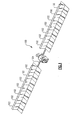
- FIG 2 illustrates an example solar panel assembly 200 which can be used as solar panel assembly 102 in Figure 1 .
- the solar panel assembly 200 includes two primary reflectors 202 connected to the support structure 204 via hinges 212. Also connected to the support structure 204 is a heat pipe radiator 206.
- the heat pipe radiator 206 is connected to a concentrated photovoltaic array 208 on an end opposite the support structure 204. Additionally connected to the heat pipe radiator 206 are hinges 210.
- the hinges 210 operate to connect the solar panel assembly 200 to other solar panel assemblies in a folded configuration during deployment, and allow the solar panel assemblies 102 to fully unfold during the satellite 100 deployment.
- the primary reflectors 202 While the satellite 100 is folded for transport, the primary reflectors 202 are substantially parallel to and adjacent to the heat pipe radiator 206. Once the satellite 100 is deployed, the primary reflectors 202 rotate away from the heat pipe radiator 206 to a desired angle.
- the desired angle can be any angle which allows the primary reflector 202 to direct reflected light onto the concentrated photovoltaic array 208.
- the primary reflectors 202 can be at a 90° angle relative to the heat pipe radiator 206.
- the light reflects off of the primary reflectors 202 and onto the concentrated photovoltaic array 208, the light is converted into electrical energy using known photovoltaic energy generation techniques. The energy can then be used to power the satellite 100.
- the photovoltaic technique produces excess heat as a byproduct of power generation.
- FIG 3 illustrates a modified concentrated photovoltaic assembly 300 which can be used as a solar assembly 102 in Figure 1 , with like numerals indicating like elements.
- the example concentrated photovoltaic assembly of Figure 3 additionally includes a top plane 314 at angles to the heat pipe radiator 206.
- the top plane 314 has a concentrated photovoltaic array 208 facing the primary reflector 202.
- the concentrated photovoltaic array collects more solar energy for power conversion than in the example of Figure 2 .
- This gain results from reduction of reflection loss on the concentrated photovoltaic array 208 compared to the example of Figure 2 .
- the concentrated photovoltaic array 208 generates large amounts of excess heat as a byproduct of the power generation.
- Figure 4 illustrates another modified concentrated photovoltaic assembly 400 which can be used as a solar assembly 102 in Figure 1 , with like numerals indicating like elements.
- the example concentrated photovoltaic assembly of Figure 4 additionally includes a secondary reflector 414, which is not utilized in the example of Figure 2 .
- the secondary reflector 414 collects light reflected from the primary reflectors 202, and redirects the light to the concentrated photovoltaic array 208. More light can be collected using the secondary reflectors than in the example of Figure 2 , as the primary reflectors 202 have a wider and more direct area onto which they can focus the light, thereby allowing more light to be captured.
- the concentrated photovoltaic array 208 generates large amounts of excess heat as a byproduct of the power generation.
- the surrounding atmosphere absorbs the heat via heat convection, thereby preventing or limiting any overheating.
- the rate at which the waste heat can be rejected from the concentrated photovoltaic array in any environment is related to the exposed surface area contacting a fluid, into which the excess heat is transferred.
- the fluid would typically be air.
- Environmental conditions can prevent the excess heat from being adequately rejected away from the CPV. By way of example, a lack of an atmosphere, such as in space, will reduce the rate at which the excess heat can be radiated off of the exposed surface area.
- the solar panel array 100, 200, 300 or 400 may include a heat pipe radiator 206.
- the heat pipe radiator 206 includes heat pipes 220 which connect the concentrated photovoltaic array 208 to the support structure 104.
- the heat pipe radiator also includes radiating fins 230 mounted on two sides of heat pipes 220, which provide structure continuation and heat radiation surface areas.
- the radiating fins illustrated in Figure 4 can be utilized in any of the described examples.
- the heat pipes 220 are connected to the concentrated photovoltaic array 208 and the support structure 104 to transmit heat away from the concentrated photovoltaic array 208.
- the radiating fins 230 provide a larger exposed surface area for the heat to be radiated from, thereby increasing the rate at which heat is radiated into the surrounding environment.
- the use of a heat pipe radiator provides further benefits in that the excess heat is drawn directly away from the CPV rather than relying on radiation across.
- a heat pipe 220 is a sealed pipe or tube made of a material with high thermal conductivity, such as copper or aluminum. All air is removed from the empty heat pipe and the pipe is partially filled with a working fluid, (or coolant), chosen to match the operating temperature. Some example fluids are water, ethanol, acetone, sodium, or mercury. The partial vacuum inside the tube is near or below the vapor pressure of the fluid, and consequently a portion of the fluid will be in the liquid phase and another portion will be in the gas phase.
- the heat pipe 220 transfers the heat from a hot end, connected to the concentrated photovoltaic array 208 through a thermally conductive connection, by heating up the liquid portion of the coolant resulting in phase change to gas phase. The heated gas then condenses at the cold end of the heat pipe, releasing the heat into radiator surface areas, which then release the heat into the surrounding environment. The condensed coolant can be transported back to the hot end through wicks inside the heat pipe via capillary force.
- the primary reflector 202 is a flat surface Fresnel reflector. It is made of a plurality of Fresnel grooves and each groove has a specific slope of inclination. When illuminated by solar rays it concentrates incoming solar rays to the concentrated photovoltaic array 208 or to the secondary reflector 414.
Landscapes
- Photovoltaic Devices (AREA)
- Optical Elements Other Than Lenses (AREA)
Abstract
Description
- The present disclosure is directed to a concentrated photovoltaic array, and more specifically to such an array providing power to a satellite.
- Photovoltaic arrays (also known as Solar Power Generators) are often used where typical stored energy solutions, such as batteries, are unacceptable, and where a device needing power will have access to a steady source of light. As an example, a terrestrial solar power farm utilizes photovoltaic arrays to generate power for supplying power to the power grid. The atmosphere surrounding the arrays typically provides adequate heat convection to remove excess heat and prevent overheating, such that thermal management is not an issue.
- An exemplary reflective concentrated photovoltaic array includes a support structure with multiple primary reflectors connected to it. The primary reflectors extend outward from the center structure, and reflect light onto a concentrated photo voltaic array. The concentrated photovoltaic array is connected to the center structure via a heat pipe radiator.
- An exemplary embodiment includes a satellite with at least one of the above described concentrated photovoltaic arrays connected to a main body. The concentrated photovoltaic array is used to generate power for the satellite's operations, and uses the described heat pipe radiator to remove heat from the solar panels.
- These and other features of the present invention can be best understood from the following specification and drawings, the following of which is a brief description.
-
-
Figure 1 illustrates a satellite capable of receiving power from a plurality of attached photovoltaic arrays. -
Figure 2 illustrates an example photovoltaic array. -
Figure 3 illustrates an example photovoltaic array. -
Figure 4 illustrates an example photovoltaic array with an additional secondary reflector. -
Figure 1 illustrates asatellite 100 havingsolar panel assemblies 102 to generate electric power to operate thesatellite 100. The solar panel assemblies 102 begin in a folded position to conserve space on the launch vehicle. When thesatellite 100 is deployed, thesolar panels 102 unfold and extend outward from thesatellite 100, such that thepanels 102 are oriented toward a light source, typically the sun, in order to receive the light required for photovoltaic power generation. Each of thesolar panel assemblies 102 is independently capable of generating power, and is connected within thesatellite 100 through asupport structure 104, which may also be referred to as a center structure. -
Figure 2 illustrates an examplesolar panel assembly 200 which can be used assolar panel assembly 102 inFigure 1 . Thesolar panel assembly 200 includes twoprimary reflectors 202 connected to thesupport structure 204 viahinges 212. Also connected to thesupport structure 204 is aheat pipe radiator 206. Theheat pipe radiator 206 is connected to a concentratedphotovoltaic array 208 on an end opposite thesupport structure 204. Additionally connected to theheat pipe radiator 206 arehinges 210. Thehinges 210 operate to connect thesolar panel assembly 200 to other solar panel assemblies in a folded configuration during deployment, and allow the solar panel assemblies 102 to fully unfold during thesatellite 100 deployment. - While the
satellite 100 is folded for transport, theprimary reflectors 202 are substantially parallel to and adjacent to theheat pipe radiator 206. Once thesatellite 100 is deployed, theprimary reflectors 202 rotate away from theheat pipe radiator 206 to a desired angle. The desired angle can be any angle which allows theprimary reflector 202 to direct reflected light onto the concentratedphotovoltaic array 208. By way of example, theprimary reflectors 202 can be at a 90° angle relative to theheat pipe radiator 206. When light reflects off of theprimary reflectors 202 and onto the concentratedphotovoltaic array 208, the light is converted into electrical energy using known photovoltaic energy generation techniques. The energy can then be used to power thesatellite 100. The photovoltaic technique produces excess heat as a byproduct of power generation. -
Figure 3 illustrates a modified concentratedphotovoltaic assembly 300 which can be used as asolar assembly 102 inFigure 1 , with like numerals indicating like elements. The example concentrated photovoltaic assembly ofFigure 3 additionally includes atop plane 314 at angles to theheat pipe radiator 206. Thetop plane 314 has a concentratedphotovoltaic array 208 facing theprimary reflector 202. On the opposite side oftop plane 314 there is heat sink thermally coupled withheat pipe radiator 206. In this configuration the concentrated photovoltaic array collects more solar energy for power conversion than in the example ofFigure 2 . This gain results from reduction of reflection loss on the concentratedphotovoltaic array 208 compared to the example ofFigure 2 . In this example, as in the first example, the concentratedphotovoltaic array 208 generates large amounts of excess heat as a byproduct of the power generation. -
Figure 4 illustrates another modified concentratedphotovoltaic assembly 400 which can be used as asolar assembly 102 inFigure 1 , with like numerals indicating like elements. The example concentrated photovoltaic assembly ofFigure 4 additionally includes asecondary reflector 414, which is not utilized in the example ofFigure 2 . Thesecondary reflector 414 collects light reflected from theprimary reflectors 202, and redirects the light to the concentratedphotovoltaic array 208. More light can be collected using the secondary reflectors than in the example ofFigure 2 , as theprimary reflectors 202 have a wider and more direct area onto which they can focus the light, thereby allowing more light to be captured. In this example, as in the first example, the concentratedphotovoltaic array 208 generates large amounts of excess heat as a byproduct of the power generation. - The excess heat rejects from the front and the back of the
photovoltaic array 208. In terrestrial applications, the surrounding atmosphere absorbs the heat via heat convection, thereby preventing or limiting any overheating. The rate at which the waste heat can be rejected from the concentrated photovoltaic array in any environment is related to the exposed surface area contacting a fluid, into which the excess heat is transferred. In a terrestrial embodiment the fluid would typically be air. Environmental conditions can prevent the excess heat from being adequately rejected away from the CPV. By way of example, a lack of an atmosphere, such as in space, will reduce the rate at which the excess heat can be radiated off of the exposed surface area. - To remove heat, the
solar panel array heat pipe radiator 206. Theheat pipe radiator 206 includesheat pipes 220 which connect the concentratedphotovoltaic array 208 to thesupport structure 104. The heat pipe radiator also includes radiatingfins 230 mounted on two sides ofheat pipes 220, which provide structure continuation and heat radiation surface areas. The radiating fins illustrated inFigure 4 can be utilized in any of the described examples. Theheat pipes 220 are connected to the concentratedphotovoltaic array 208 and thesupport structure 104 to transmit heat away from the concentratedphotovoltaic array 208. Theradiating fins 230 provide a larger exposed surface area for the heat to be radiated from, thereby increasing the rate at which heat is radiated into the surrounding environment. The use of a heat pipe radiator provides further benefits in that the excess heat is drawn directly away from the CPV rather than relying on radiation across. - A
heat pipe 220 is a sealed pipe or tube made of a material with high thermal conductivity, such as copper or aluminum. All air is removed from the empty heat pipe and the pipe is partially filled with a working fluid, (or coolant), chosen to match the operating temperature. Some example fluids are water, ethanol, acetone, sodium, or mercury. The partial vacuum inside the tube is near or below the vapor pressure of the fluid, and consequently a portion of the fluid will be in the liquid phase and another portion will be in the gas phase. Theheat pipe 220 transfers the heat from a hot end, connected to the concentratedphotovoltaic array 208 through a thermally conductive connection, by heating up the liquid portion of the coolant resulting in phase change to gas phase. The heated gas then condenses at the cold end of the heat pipe, releasing the heat into radiator surface areas, which then release the heat into the surrounding environment. The condensed coolant can be transported back to the hot end through wicks inside the heat pipe via capillary force. - The
primary reflector 202 is a flat surface Fresnel reflector. It is made of a plurality of Fresnel grooves and each groove has a specific slope of inclination. When illuminated by solar rays it concentrates incoming solar rays to the concentratedphotovoltaic array 208 or to thesecondary reflector 414. - While the above examples are directed toward applications in space, the disclosed concepts may provide significant benefits in any environment where more rapid heat radiation is desired.
- Although several examples of this invention have been disclosed, a worker of ordinary skill in this art would recognize that certain modifications would come within the scope of this invention. For that reason, the following claims should be studied to determine the true scope and content of this invention.
Claims (15)
- A reflective concentrated photovoltaic (CPV) array (200,300,400) comprising:a support structure (204);a CPV panel (208) having a light-collecting surface;a heat pipe radiator (206) at least thermally connecting said CPV panel to said support structure; anda plurality of primary reflectors (202) connected to, and extending outward from said support structure, said plurality of primary reflectors having a reflective surface oriented to reflect light onto said light-collecting surface.
- The reflective CPV array of claim 1, wherein said CPV panel (208) is further integrated with the heat pipe radiator (206) for structural support and waste heat transfer.
- The reflective CPV array of claim 1 or 2, further comprising a top plane (314) with the CPV panel mounted on the primary reflector facing side.
- The reflective CPV array of claim 1, 2, or 3, wherein the primary reflector (202) comprises a plurality of Fresnel grooves, each groove having a slope of inclination to concentrate incoming solar rays to the CPV panel.
- The reflective CPV array of claim 1 or 2, further comprising a secondary reflector (414) oriented to receive light reflected from said plurality of primary reflectors and reflect said light toward said CPV panel; preferably wherein the primary reflector (202) comprises a plurality of Fresnel grooves, each groove having a slope of inclination to concentrate incoming solar rays to the secondary reflector.
- The reflective CPV array of any preceding claim, further comprising at least one hinge (212) connecting each of said plurality of primary reflectors to said support structure.
- The reflective CPV array of any preceding claim, wherein said heat pipe radiator comprises at least one connector (210) for connecting to additional reflective CPV arrays; preferably wherein said connector is a hinge (210).
- The reflective CPV array of any preceding claim, wherein the heat pipe radiator comprises a plurality of heat pipes (220) and a radiating fin surface (230) connecting each of said heat pipes.
- The reflective CPV array of claim 8, wherein each of said heat pipes is a thermal conductor and is connected to said CPV panel via a thermal conductor.
- The reflective CPV array of claim 8 or 9, wherein each of said heat pipes is connected to said support structure.
- The reflective CPV array of claim 10, additionally comprising a heat sink thermally connected to said heat pipe radiator; preferably wherein said heat sink comprises a fin shaped heat sink for radiating heat.
- A satellite (100) comprising;
a main body;
a support structure (104) extending from said main body;
at least one solar panel assembly (102) connected to said support structure and electrically coupled to said main body, such that power generated in the solar panel is transmitted to the main body;
the at least one solar panel assembly having a concentrated photovoltaic array (CPV) panel (208), a heat pipe radiator (206), and a plurality of primary reflectors (202) connected to and extending outward from said support structure, each of said plurality of primary reflectors having a reflective surface oriented towards said CPV panel for reflecting light onto said CPV panel; and
said heat pipe radiator connecting said CPV panel to said support structure. - The satellite of claim 12, wherein said heat pipe radiator comprises a plurality of heat pipes (220) connected to said CPV panel on a first end via a thermal conductor, and connected to said support structure on a second end, opposite said first end.
- A method of removing heat from a reflective concentrated photovoltaic (CPV) array comprising the steps of:transferring heat from a CPV (208) panel to a heat pipe (230); anddirecting the heat from said CPV panel and toward a heat pipe radiator (206).
- The method of claim 14, further comprising radiating the heat into a surrounding environment.
Applications Claiming Priority (1)
| Application Number | Priority Date | Filing Date | Title |
|---|---|---|---|
| US12/507,988 US20110017875A1 (en) | 2009-07-23 | 2009-07-23 | Photovoltaic array |
Publications (2)
| Publication Number | Publication Date |
|---|---|
| EP2278629A2 true EP2278629A2 (en) | 2011-01-26 |
| EP2278629A3 EP2278629A3 (en) | 2014-06-04 |
Family
ID=42938210
Family Applications (1)
| Application Number | Title | Priority Date | Filing Date |
|---|---|---|---|
| EP10251305.8A Withdrawn EP2278629A3 (en) | 2009-07-23 | 2010-07-22 | Reflective photovoltaic concentrator |
Country Status (2)
| Country | Link |
|---|---|
| US (1) | US20110017875A1 (en) |
| EP (1) | EP2278629A3 (en) |
Cited By (1)
| Publication number | Priority date | Publication date | Assignee | Title |
|---|---|---|---|---|
| EP3557157A4 (en) * | 2016-12-30 | 2020-07-22 | Bolymedia Holdings Co. Ltd. | CONCENTRATING SOLAR DEVICE |
Families Citing this family (2)
| Publication number | Priority date | Publication date | Assignee | Title |
|---|---|---|---|---|
| CN120200550B (en) * | 2025-03-24 | 2026-02-10 | 北京星辰未来空间技术研究院 | A space-based parabolic cylindrical concentrating energy system |
| CN121158250A (en) * | 2025-11-19 | 2025-12-19 | 北京星辰未来空间技术研究院 | Space concentrating solar cell system based on concentrating-radiating collaborative design |
Family Cites Families (15)
| Publication number | Priority date | Publication date | Assignee | Title |
|---|---|---|---|---|
| US4784700A (en) * | 1987-05-26 | 1988-11-15 | General Dynamics Corp./Space Systems Div. | Point focus solar concentrator using reflector strips of various geometries to form primary and secondary reflectors |
| US5118361A (en) * | 1990-05-21 | 1992-06-02 | The Boeing Company | Terrestrial concentrator solar cell module |
| US5154777A (en) * | 1990-02-26 | 1992-10-13 | Mcdonnell Douglas Corporation | Advanced survivable space solar power system |
| US6080927A (en) * | 1994-09-15 | 2000-06-27 | Johnson; Colin Francis | Solar concentrator for heat and electricity |
| US5660644A (en) * | 1995-06-19 | 1997-08-26 | Rockwell International Corporation | Photovoltaic concentrator system |
| US5785280A (en) * | 1995-07-20 | 1998-07-28 | Space Systems/Loral, Inc. | Hybrid solar panel array |
| US5865905A (en) * | 1996-09-30 | 1999-02-02 | Boeing North American, Inc. | Rolled film solar concentrator |
| US5949212A (en) * | 1997-06-05 | 1999-09-07 | The Boeing Company | Integrated solar cell array and power regulator |
| US5924479A (en) * | 1998-11-03 | 1999-07-20 | Egbert; Mark A. | Heat exchanger with heat-pipe amplifier |
| US6981377B2 (en) * | 2002-02-25 | 2006-01-03 | Outfitter Energy Inc | System and method for generation of electricity and power from waste heat and solar sources |
| AU2003248539A1 (en) * | 2002-05-17 | 2003-12-02 | William M. Janvrin | Photovoltaic module with adjustable heat sink and method of fabrication |
| US7459064B2 (en) * | 2003-11-24 | 2008-12-02 | Hamilton Sundstrand Corporation | Solar electrolysis power source |
| US7193850B2 (en) * | 2004-08-31 | 2007-03-20 | Hamilton Sundstrand Corporation | Integrated heat removal and vibration damping for avionic equipment |
| KR20080109754A (en) * | 2006-03-13 | 2008-12-17 | 그린 볼츠, 인코포레이티드 | Tracking solar power system |
| US20080134497A1 (en) * | 2006-12-11 | 2008-06-12 | Sunmodular, Inc. | Modular solar panels with heat exchange & methods of making thereof |
-
2009
- 2009-07-23 US US12/507,988 patent/US20110017875A1/en not_active Abandoned
-
2010
- 2010-07-22 EP EP10251305.8A patent/EP2278629A3/en not_active Withdrawn
Non-Patent Citations (1)
| Title |
|---|
| None |
Cited By (1)
| Publication number | Priority date | Publication date | Assignee | Title |
|---|---|---|---|---|
| EP3557157A4 (en) * | 2016-12-30 | 2020-07-22 | Bolymedia Holdings Co. Ltd. | CONCENTRATING SOLAR DEVICE |
Also Published As
| Publication number | Publication date |
|---|---|
| EP2278629A3 (en) | 2014-06-04 |
| US20110017875A1 (en) | 2011-01-27 |
Similar Documents
| Publication | Publication Date | Title |
|---|---|---|
| US6118067A (en) | Method and apparatus for improved solar concentration arrays | |
| CN2913955Y (en) | Heat self-dissipating solar energy accumulation type photovoltaic electricity generating system | |
| US9029684B2 (en) | Hybrid solar receiver and concentrating solar system comprising the same | |
| US20070289622A1 (en) | Integrated solar energy conversion system, method, and apparatus | |
| CN106160658B (en) | A kind of photovoltaic and photothermal solar association system of the full spectrum of light-focusing type | |
| EP2857775A1 (en) | Solar photo-thermal receiving device | |
| US20130074906A1 (en) | Apparatus for converting thermal energy to electrical energy | |
| CN101098112A (en) | Self-radiating solar energy concentrating photovoltaic power generation device | |
| WO2009108896A1 (en) | Concentrators for solar power generating systems | |
| CN101983434B (en) | Solar cell device with high heat dissipation efficiency | |
| US4172740A (en) | Solar energy system | |
| KR20160136528A (en) | Solar thermal and photovoltaic composite energy water heater | |
| US20110017875A1 (en) | Photovoltaic array | |
| US20080137205A1 (en) | Shield for solar radiation collector | |
| US6857425B2 (en) | Solar energy collector system | |
| KR101237306B1 (en) | Concentrated photovoltaic cell module cooler for solar energy conversion apparatus | |
| WO2012076847A1 (en) | Solar energy apparatus with a combined photovoltaic and thermal power generation system | |
| US20090308433A1 (en) | Method and apparatus for cooling of solar power cells | |
| US20100116317A1 (en) | Inter-Facing Solar Panels | |
| JP2003137199A (en) | Solar battery panel and space machine having solar battery panel | |
| CN102270690A (en) | Solar energy utilization device | |
| EP2827383B1 (en) | A hybrid solar energy converter | |
| JP2023548401A (en) | Multi-temperature heat collection system | |
| KR20160082201A (en) | A Portable Power Generator Using Solar Energy | |
| CN202339930U (en) | Solar energy utilization device |
Legal Events
| Date | Code | Title | Description |
|---|---|---|---|
| PUAI | Public reference made under article 153(3) epc to a published international application that has entered the european phase |
Free format text: ORIGINAL CODE: 0009012 |
|
| AK | Designated contracting states |
Kind code of ref document: A2 Designated state(s): AL AT BE BG CH CY CZ DE DK EE ES FI FR GB GR HR HU IE IS IT LI LT LU LV MC MK MT NL NO PL PT RO SE SI SK SM TR |
|
| AX | Request for extension of the european patent |
Extension state: BA ME RS |
|
| RAP1 | Party data changed (applicant data changed or rights of an application transferred) |
Owner name: HAMILTON SUNDSTRAND SPACE SYSTEMS INTERNATIONAL, I |
|
| PUAL | Search report despatched |
Free format text: ORIGINAL CODE: 0009013 |
|
| AK | Designated contracting states |
Kind code of ref document: A3 Designated state(s): AL AT BE BG CH CY CZ DE DK EE ES FI FR GB GR HR HU IE IS IT LI LT LU LV MC MK MT NL NO PL PT RO SE SI SK SM TR |
|
| AX | Request for extension of the european patent |
Extension state: BA ME RS |
|
| RIC1 | Information provided on ipc code assigned before grant |
Ipc: H02S 40/22 20140101ALI20140430BHEP Ipc: H01L 31/052 20140101AFI20140430BHEP Ipc: H02S 40/42 20140101ALI20140430BHEP |
|
| RAP1 | Party data changed (applicant data changed or rights of an application transferred) |
Owner name: AEROJET ROCKETDYNE OF DE, INC. |
|
| 17P | Request for examination filed |
Effective date: 20141204 |
|
| RBV | Designated contracting states (corrected) |
Designated state(s): AL AT BE BG CH CY CZ DE DK EE ES FI FR GB GR HR HU IE IS IT LI LT LU LV MC MK MT NL NO PL PT RO SE SI SK SM TR |
|
| 17Q | First examination report despatched |
Effective date: 20150622 |
|
| STAA | Information on the status of an ep patent application or granted ep patent |
Free format text: STATUS: THE APPLICATION IS DEEMED TO BE WITHDRAWN |
|
| 18D | Application deemed to be withdrawn |
Effective date: 20170201 |