EP2278454B1 - Method for correct-by-construction development of real-time-systems - Google Patents
Method for correct-by-construction development of real-time-systems Download PDFInfo
- Publication number
- EP2278454B1 EP2278454B1 EP10166520.6A EP10166520A EP2278454B1 EP 2278454 B1 EP2278454 B1 EP 2278454B1 EP 10166520 A EP10166520 A EP 10166520A EP 2278454 B1 EP2278454 B1 EP 2278454B1
- Authority
- EP
- European Patent Office
- Prior art keywords
- task
- time
- mode
- execution
- real
- Prior art date
- Legal status (The legal status is an assumption and is not a legal conclusion. Google has not performed a legal analysis and makes no representation as to the accuracy of the status listed.)
- Active
Links
- 238000000034 method Methods 0.000 title claims description 25
- 238000011161 development Methods 0.000 title description 6
- 238000010276 construction Methods 0.000 title description 5
- 230000001360 synchronised effect Effects 0.000 claims description 20
- 238000013461 design Methods 0.000 claims description 7
- 238000004590 computer program Methods 0.000 claims 2
- 230000010365 information processing Effects 0.000 claims 2
- 238000004891 communication Methods 0.000 description 17
- 230000000694 effects Effects 0.000 description 17
- 238000010586 diagram Methods 0.000 description 14
- 230000006399 behavior Effects 0.000 description 11
- 230000006870 function Effects 0.000 description 11
- 230000001960 triggered effect Effects 0.000 description 10
- 238000004364 calculation method Methods 0.000 description 8
- 230000002123 temporal effect Effects 0.000 description 7
- 101100293589 Kluyveromyces lactis (strain ATCC 8585 / CBS 2359 / DSM 70799 / NBRC 1267 / NRRL Y-1140 / WM37) NAR1 gene Proteins 0.000 description 5
- 101100409519 Schizosaccharomyces pombe (strain 972 / ATCC 24843) let1 gene Proteins 0.000 description 5
- 101100006960 Caenorhabditis elegans let-2 gene Proteins 0.000 description 3
- 238000013459 approach Methods 0.000 description 3
- 230000008859 change Effects 0.000 description 3
- 230000007246 mechanism Effects 0.000 description 3
- 230000008569 process Effects 0.000 description 3
- 230000008901 benefit Effects 0.000 description 2
- 230000003111 delayed effect Effects 0.000 description 2
- 238000013178 mathematical model Methods 0.000 description 2
- 238000012544 monitoring process Methods 0.000 description 2
- 230000000737 periodic effect Effects 0.000 description 2
- 238000012545 processing Methods 0.000 description 2
- 230000035484 reaction time Effects 0.000 description 2
- 238000005070 sampling Methods 0.000 description 2
- 238000012163 sequencing technique Methods 0.000 description 2
- 101150039208 KCNK3 gene Proteins 0.000 description 1
- 238000004458 analytical method Methods 0.000 description 1
- 230000009286 beneficial effect Effects 0.000 description 1
- 238000012937 correction Methods 0.000 description 1
- 230000007812 deficiency Effects 0.000 description 1
- 230000001419 dependent effect Effects 0.000 description 1
- 238000005516 engineering process Methods 0.000 description 1
- 230000010354 integration Effects 0.000 description 1
- 230000003993 interaction Effects 0.000 description 1
- 238000004519 manufacturing process Methods 0.000 description 1
- 238000013507 mapping Methods 0.000 description 1
- 230000003252 repetitive effect Effects 0.000 description 1
- 230000010076 replication Effects 0.000 description 1
- 238000011160 research Methods 0.000 description 1
- 238000000926 separation method Methods 0.000 description 1
- 238000004088 simulation Methods 0.000 description 1
Images
Classifications
-
- G—PHYSICS
- G06—COMPUTING; CALCULATING OR COUNTING
- G06F—ELECTRIC DIGITAL DATA PROCESSING
- G06F8/00—Arrangements for software engineering
- G06F8/20—Software design
-
- G—PHYSICS
- G06—COMPUTING; CALCULATING OR COUNTING
- G06F—ELECTRIC DIGITAL DATA PROCESSING
- G06F9/00—Arrangements for program control, e.g. control units
- G06F9/06—Arrangements for program control, e.g. control units using stored programs, i.e. using an internal store of processing equipment to receive or retain programs
- G06F9/46—Multiprogramming arrangements
- G06F9/48—Program initiating; Program switching, e.g. by interrupt
- G06F9/4806—Task transfer initiation or dispatching
- G06F9/4843—Task transfer initiation or dispatching by program, e.g. task dispatcher, supervisor, operating system
- G06F9/4881—Scheduling strategies for dispatcher, e.g. round robin, multi-level priority queues
- G06F9/4887—Scheduling strategies for dispatcher, e.g. round robin, multi-level priority queues involving deadlines, e.g. rate based, periodic
Definitions
- the present invention relates to systems that have to meet strict real-time requirements (real-time systems), especially to a method for the correct-by-construction development of real-time control systems.
- Real-time systems are often employed in control systems to implement control laws for controlling technical processes.
- these real-time systems comprise distributed hardware, i.e. the software for the various tasks that are necessary for control purposes is executed on separated processors.
- Conventional systems for executing distributed software may comprise a plurality of nodes and a communication channel, wherein the system is configured such that the nodes are allowed to transmit data across the communication channel. Examples of such systems also include so called embedded systems in which the nodes can also be referred to as electronic control units (abbreviated ECUs).
- An ECU may perform the tasks defined by software and may be encapsulated in the device which it controls.
- Examples of embedded systems include automotive systems, automation systems and avionics systems.
- An automotive system may in particular include a plurality of devices for operating brakes, a plurality of devices for sensing wheel speeds, a device for sensing the velocity of a vehicle etc. which communicate across a communication channel and which are configured to perform an operation of an anti-blocking system (ABS). Since the operation of an anti-blocking system is safety-critical to the vehicle and its passengers, it is required that repetitive readings of sensors, calculations and updating of actuators are performed periodically, for example, every five milliseconds.
- ABS anti-blocking system
- Conventional software designed for real-time systems is typically configured such that the software is separated into a plurality of tasks which the system has to perform.
- the tasks can be executed by one ECU (i.e. one node) or by different nodes, whereby each single node may execute one or more tasks.
- Some tasks may use output signals of sensors as their input, other tasks may provide output signals to actuators.
- Different tasks may communicate with each other by exchanging data.
- a schedule and the execution of tasks may depend on external events which can be detected by the system by means of one or more sensors.
- a mode of operation of any system on any node may change over time, and also demands on the communication channel with respect to band width may change over time.
- it has to be ensured that a given band width provided by the communication channel is sufficient to guarantee fault free operation of the hard real-time system during each possible combination of operational modes of all of the involved nodes.
- Giotto provides a programming abstraction for hard real-time applications which exhibit time-periodic and multi-modal behavior, as in automotive, aerospace, and manufacturing control.
- T.A. Henzinger, C.M. Kirsch, R. Majumdar, S. Matic: “Time-Safety Checking for Embedded Programs", in Proc. 2nd Int. Conf. on Embedded Software (EMSOFT'2002), Grenoble, France, October 7-9 the authors present an approach to the compilation of Giotto, wherein the Giotto compiler generates code for a virtual machine, called the E-machine, which can be ported to different platforms.
- the Giotto compiler also checks if the generated E-code is time safe for a given platform, that is, if the platform offers sufficient performance to ensure that the E-code is executed in a timely fashion that conforms with the Giotto semantics.
- Typical activities of the software engineer include decomposing the necessary computational activities into periodic tasks, assigning tasks to CPUs and setting task priorities to meet the desired hard real-time constraints under the given scheduling mechanism and hardware performance, and achieving a degree of fault tolerance through replication and error correction.
- Giotto provides an intermediate level of abstraction, which permits the software engineer to communicate more effectively with the control engineer.
- a software architecture of the implementation is defined which specifies its functionality and timing. Functionality and timing are sufficient and necessary for ensuring that the implementation is consistent with the mathematical model of the control design.
- "Correct-by-construction development” means that the implementation of an embedded system, that corresponds exactly to its specification, is automatically generated. This allows for abstracting away from the realization of the software architecture on a specific platform, and frees the software engineer from worrying about issues such as hardware performance and scheduling mechanism while communicating with the control engineer. After coming up with a Giotto program, the second task of the software engineer is still to implement the program on the given platform.
- a computer-based method for automatically constructing a real-time system includes at least one module, each module having at least one mode.
- the method comprises: defining a mode period for each mode for a repeated execution of the respective mode by the corresponding module; for each mode, defining one or more synchronous tasks to be executed by the real-time system, whereby each synchronous task is associated with a logical execution time during which the task execution has to be completed; defining an integer number of time-slots for the mode period of each mode; assigning to each task at least one time slot during which the task is to be executed.
- the computer-based method for automatically constructing a real-time system comprises: defining one or more synchronous tasks to be executed by the real-time system, whereby each synchronous task is associated with a logical execution time during which the task execution has to be completed; splitting at least one task into a first part and a second part, the first part having a logical execution time shorter than the second part, whereby the first part is configured to calculate an output from at least one input and a precalculated data that is provided by the second part of a prior invocation of the task.
- the computer-based method for automatically constructing a real-time system comprises: defining one or more synchronous tasks to be executed by the real-time system, whereby each synchronous task is associated with a logical execution time during which the task execution has to be completed; receiving asynchronous events; assigning an asynchronous task to each received event; assigning a priority value to each asynchronous task; queuing the asynchronous tasks according to the priority value; scheduling the execution of the asynchronous tasks during periods when no synchronous task is executed.
- FIG. 1 shows a system 1 comprising three nodes 3 labeled as "node 1", “node 2" and “node 3", respectively, and which are connected to a communication channel 5 labeled as "bus".
- the bus is used for data communication between the nodes 3.
- the nodes are electronic devices which are in some fields of application, such as the automotive industry, referred to as electronic control units (ECU).
- ECU electronice control units
- Each node may include a dedicated piece of hardware which interfaces the node with the communication channel and which is then commonly referred to as a controller.
- the communication channel is embodied as a bus having broadcasting semantics which means that data transmitted to the communication channel from one of the nodes may be received by any of the other nodes.
- the present invention is, however, not limited to such a communication channel but encompasses also communication channels of other suitable topology and semantics.
- System 1 is configured to execute software which is composed of several modules M1, M2, M3 and M4.
- Modules are an example of a method of structuring complex software, and a module generally is a piece of software having an application programming interface (API).
- API application programming interface
- Software which is composed of plural modules allows transparent distribution of the software over plural nodes for executing the software.
- node 1 executes modules M1 and M2
- node 2 executes module M3
- node 3 executes module M4.
- FIG. 2 A more specific example of software composed of two modules is illustrated in FIG. 2 .
- the exemplary software shown in FIG. 2 comprises a first module 7 labeled as “Module Service” and a second module 8 labeled as “Module Client”.
- Each module may comprise a set of sensors 9, a set of actuators 10 and a set of modes 11.
- the sensors 9 of module 7 are labeled “S1", “S2", and the sensor 9 of module 8 is labeled "S”.
- the actuators 10 of module 7 are labeled as "A1", “A2” and “A3", and the actuators 10 of the module 8 are labeled as "A1" and "A2".
- Module 7 has two modes 11, labeled as "mode 1" and "mode 2".
- Module 8 has three modes 11, labeled as "mode 1", "mode 2" and "mode 3".
- Mode 1 of module 7 comprises two tasks labeled as "task 1" and "task 2", wherein task 1 is repetitively executed at a first period of ten milliseconds as indicated by “[10 ms]”, and task 2 is repetitively executed at a period of twenty milliseconds indicated by “[20 ms]”.
- Task invocations might adhere to the LET semantics as introduced by the Giotto programming model (see the article of T. A. Henzinger et al. mentioned in the introductory part).
- Task invocation according to LET is illustrated in the schematic diagram of FIG. 3 .
- the inputs of the task are read at the beginning of a LET period.
- the reading of the inputs is practically done in close to zero time, what is called “logical zero time” (LZT).
- LZT logic zero time
- the beginning of the LET period is indicated by the arrow labeled "release” in FIG. 3 .
- Newly calculated outputs of the task are available exactly at the end of the LET period which is indicated by an arrow labeled "terminate” in FIG. 3 .
- the physical execution of the task on the node is started at a time indicated by an arrow labeled "start” and terminated at a time indicated by an arrow labeled “stop”, wherein the physical execution of the task is suspended at a time indicated by an arrow labeled “suspend” and resumed at a time indicated by an arrow labeled “resume”.
- the time of physical execution within the LET period is not defined by LET. However, it is a requirement that the physical execution of the task has to finish before the end of the LET period. In other words, the start of the physical execution of the task can take place at or after the beginning of the LET period, and the end of the physical execution of the task has to occur at the latest, also for the worst case, before or at the end of the LET period.
- the results of the calculation of the task are only available to the outside of the task at and after the end of the LET period rather than at the end of the physical execution of the task. This means, that before the end of the LET period, only the "old" results of the previous invocation of the task are available.
- task 1 of mode 1 of module 7 is repetitively executed at a period of ten milliseconds wherein the sensor is red exactly at the beginning of the ten-millisecond-period (in LZT) and wherein the results of the calculation of task 1 are made available to actuator A1 exactly at the end of the ten-millisecond-period.
- FIG. 2 also illustrates communication between tasks.
- task 1 in mode 1 of module 8 delivers its output as inputs to task 2 and task 3.
- FIG. 2 illustrates communication of tasks across module boundaries.
- An output of task 2 of mode 1 of module 7 is labeled as "task2.o" and is provided as an input to task 1 of mode 1 of module 8.
- composition of the software of a set of modules and the definition of the tasks of the modules according to LET semantics allows transparent distribution of the software across one or plural nodes, wherein a temporal behavior of the software is guaranteed.
- adding a new module will never affect the observable temporal behavior of other modules as long as internal scheduling mechanisms of the respective nodes guarantee a conformance to LET, given that worst case execution times (WCET) and execution rates are known for all tasks.
- WET worst case execution times
- FIG. 4 is an illustration of the execution of modules M1 and M2 by node 1 shown in FIG. 1 .
- Module M1 has one task, "task 1", with LET1
- module M2 has one task, "task 2", with LET2.
- Task 2 uses the output of task 1 as input, and LET1 of task 1 is twice as large as LET2 of task 2.
- the rectangles in FIG. 4 schematically indicate the physical execution times of task 1 and task 2.
- the outputs of task 1 are made available to task 2 at the end of the logical execution time LET1 of task 1 as indicated by arrow 13. This can be achieved by copying values from a location of memory associated with task 1 to a location of memory associated with task 2. Such copying will take close to zero time (logical zero time, LZT) on a single node.
- LZT logical zero time
- Both the third and fourth invocations of task 2 shown in FIG. 4 will use the output of the first invocation of task 1. This means that the fourth invocation of task 2 will not use the output of the second invocation of task 1 even though physical execution of the second invocation of task 1 is already completed when the physical execution of the fourth invocation of task 2 begins.
- a mode period p is assigned to each mode (cf. modes 11 of FIG. 2 ) and a frequency number f is assigned to each task of the mode.
- the activity of a task is performed f times per mode period p.
- the LET of the task is implicitly specified as p/f and the mode period is filled with f such task invocations.
- the result of the above-mentioned description of the temporal behavior of the tasks according to the known Giotto language is illustrated in the timing diagrams of FIG. 5 .
- the exemplary system has only one module including a single mode. Two tasks "task 1" and “task 2" are repeatedly executed within that mode, whereby task 2 receives an output of task 1 as an input.
- the mode period p is, for example, 120 ms (milliseconds) and the frequency f is 6. According, the Giotto language the result will be as shown in FIG.
- the output of the first, the third and the fifth invocation of task 1 is discarded.
- task 1 is executed redundantly as its output is not used for every invocation.
- the computation time consumed for the redundant task invocations can not be used for other tasks.
- the processor executing the code has to be designed for a load higher than actually necessary for the respective control application.
- a method for defining the temporal behavior of a real-time system allows for assigning the single task invocations to predefined time slots within the mode period p.
- task 1 having a LET of 20 ms
- the duration of a time slot is defined as p/f (the mode period divided by frequency, i.e. the duration of a time slot corresponds to the LET of the respective task).
- the LET of a task and the frequency f are decoupled and the software engineer may specify the time slots during which a task is to be executed and during which the processor is free to process other tasks.
- the corresponding timing diagram is illustrated in FIG. 6 .
- the redundant execution of tasks may be beneficially avoided. In practice, it allows one to specify, for example, breaks between invocations or to define that a task should be invoked at the beginning or at the end of a mode period only. As another beneficial consequence, it may help the task scheduler to find a feasible schedule and it may reduce the latency in the data flow between invocations of communicating tasks.
- reaction time of a (digital) controller should be within approximately ten percent of the sample time of a task in order to achieve stable controller behavior. Since, when employing the Giotto model, the reaction time equals exactly the sample time, a high degree of oversampling is required in order to achieve an acceptable result.
- a method for defining the temporal behavior of real-time systems makes use of the concepts of "task splitting" and "task sequences" as explained below.
- a Giotto task is associated with a single external function that represents the body (i.e. its main routine) of the task.
- a task may be associated with two external functions, i.e. the body of the task is "split" into
- the LZT function (output function) is called first at the LET start and provides the new output values in a very short time, i.e. in LZT.
- the long running function is executed during the LET and might prepare the internal state of the task by some advance calculations such that the next call of the LZT function can be done fast, i.e. in LZT. This can be utilized e.g. for digital controllers which need to evaluate a polynomial as the core of their implementation.
- a task sequence comprises a task invocation followed by a set of actuator updates.
- the actuator updates of a task sequence are carried out right after the outputs of the respective task are available, that is at the beginning of the LET if the task is split so that a LZT function is available.
- the concepts of task splitting and task sequencing are schematically illustrated in the timing diagram of FIG. 7 .
- the diagram illustrates one invocation of a task labeled "task 1".
- Task 1 is split into a LZT task and a task called "advance calculation”.
- Task1 reads sensor information at the beginning of the task's LET and, in contrast to known methods, updates the actuators in close to zero time, i.e. in LZT, instead of at the end of the LET. After the actuator update, calculations necessary for the next task invocation might be performed during the LET.
- the method for defining the temporal behavior of real time systems also considers asynchronous task invocations and actuator updates.
- An asynchronous activity sequence i.e. the task invocation that might be followed by an actuator update
- events are: a hardware interrupt, an asynchronous timer, or a task output port update.
- a (non maskable) hardware interrupt may usually have the highest priority in the system and may be used, for example, for connecting the system with asynchronous input devices. It may even interrupt synchronous activities. However, the impact of hardware interrupts on the timing of synchronous activities should be minimized. In addition, it is assumed that a maskable interrupt may be switched off until the associated event is executed. This reduces the danger of denial of service due to a large number of interrupts.
- a periodic asynchronous timer may also be used as a trigger for asynchronous task invocations. Such a timer is independent from the timer that drives the synchronous activities because it uses its own time base. An asynchronous timer may for example be used as a watchdog for monitoring the execution of the time-triggered operations.
- Updating a task output port may trigger an asynchronous task invocation. It is assumed that both a synchronous and an asynchronous port update may be used as a trigger event. In case of a synchronous port update, i.e. a port update performed during a time triggered activity, the TDL semantics takes care that the impact on the timing of the synchronous activities is minimized. Port update events may e.g. be used for limit monitoring or for change notifications.
- the TDL run-time system is able to provide the synchronization of the data flow between synchronous and asynchronous activities. It has been shown that a lock-free synchronization approach with a negligible impact on the timing of the time-triggered activities is possible with the semantics described below.
- Events may be associated with a priority and are registered in a priority queue when they arrive. Processing the events is delayed and supposed to be performed sequentially by a single background thread that runs whenever there are no time-triggered activities to perform as illustrated in FIG. 8 . Reading input ports is done as part of the asynchronous execution, not at the time of registering an event. Output ports are updated right after an asynchronous task invocation has been finished. If an event reoccurs before it has started processing it will not be executed twice but remains registered once. In case of a distributed system, the communication of asynchronous output values to remote nodes is supposed to rely on asynchronous network operations, i.e. it may be delayed.
- the TDL:VisualDistributor tool allows a developer (1) to define the topology and the particular properties of a specific platform, (2) to assign the TDL module(s) to the nodes of that platform by simply dragging and dropping TDL modules, and (3) to automatically generate the platform-specific code, in particular communication schedule(s) in case of distributed platforms and code for the run-time system, but also makefiles and any platform-specific files such as OIL-files in case of using the OSEK operating system.
- the TDL:VisualDistributor tool is implemented as plug-in architecture. Platform specific node-and cluster- plug-ins provide individual code- and communication schedule generators. Depending on the designated platform different sets of properties influence the code generation process.
Description
- The present invention relates to systems that have to meet strict real-time requirements (real-time systems), especially to a method for the correct-by-construction development of real-time control systems.
- Real-time systems are often employed in control systems to implement control laws for controlling technical processes. In many applications these real-time systems comprise distributed hardware, i.e. the software for the various tasks that are necessary for control purposes is executed on separated processors. Conventional systems for executing distributed software may comprise a plurality of nodes and a communication channel, wherein the system is configured such that the nodes are allowed to transmit data across the communication channel. Examples of such systems also include so called embedded systems in which the nodes can also be referred to as electronic control units (abbreviated ECUs). An ECU may perform the tasks defined by software and may be encapsulated in the device which it controls.
- Examples of embedded systems include automotive systems, automation systems and avionics systems. An automotive system, for example, may in particular include a plurality of devices for operating brakes, a plurality of devices for sensing wheel speeds, a device for sensing the velocity of a vehicle etc. which communicate across a communication channel and which are configured to perform an operation of an anti-blocking system (ABS). Since the operation of an anti-blocking system is safety-critical to the vehicle and its passengers, it is required that repetitive readings of sensors, calculations and updating of actuators are performed periodically, for example, every five milliseconds. In practice, such a system has to fulfill strict real-time requirements, which means that a correctness of an operation depends not only upon a logical correctness of the operation but also upon a time at which it is performed. An operation performed later than a "deadline" defined within the system is, by definition, incorrect, and usually has no value. That is, the control system has to guarantee the compliance with predefined timing requirements.
- Conventional software designed for real-time systems is typically configured such that the software is separated into a plurality of tasks which the system has to perform. The tasks can be executed by one ECU (i.e. one node) or by different nodes, whereby each single node may execute one or more tasks. Some tasks may use output signals of sensors as their input, other tasks may provide output signals to actuators. Different tasks may communicate with each other by exchanging data. Thus, a schedule and the execution of tasks may depend on external events which can be detected by the system by means of one or more sensors. Thus, a mode of operation of any system on any node may change over time, and also demands on the communication channel with respect to band width may change over time. However, in the hard real-time system it has to be ensured that a given band width provided by the communication channel is sufficient to guarantee fault free operation of the hard real-time system during each possible combination of operational modes of all of the involved nodes.
- It is well-known in the art that the development of absolutely correct embedded systems with hard real-time requirements is difficult, error-prone and thus expensive. This is true for single-node systems as well as for distributed embedded systems.
- Various efforts have already been made for improving the design and development of potentially distributed embedded systems. For example, a project called "Giotto" at the University of California at Berkeley, USA resulted in a programming methodology for embedded control systems. This methodology includes a concept of defining a logical execution time of tasks under hard real-time conditions. This concept is referred to as "LET" (Logical Execution Time) and illustrated in more detail in the article of T. A. Henzinger et al., "Giotto: A time-triggered language for embedded programming", Proceedings of the First International Workshop on Embedded Software (EMSOFT), Lecture Notes in Computer Science 2211, Springer-Verlag, 2001, pages 166 to 184. Giotto provides a programming abstraction for hard real-time applications which exhibit time-periodic and multi-modal behavior, as in automotive, aerospace, and manufacturing control. In the publication T.A. Henzinger, C.M. Kirsch, R. Majumdar, S. Matic: "Time-Safety Checking for Embedded Programs", in Proc. 2nd Int. Conf. on Embedded Software (EMSOFT'2002), Grenoble, France, October 7-9, the authors present an approach to the compilation of Giotto, wherein the Giotto compiler generates code for a virtual machine, called the E-machine, which can be ported to different platforms. The Giotto compiler also checks if the generated E-code is time safe for a given platform, that is, if the platform offers sufficient performance to ensure that the E-code is executed in a timely fashion that conforms with the Giotto semantics.
- Traditional control design happens at a mathematical level of abstraction, with the control engineer manipulating differential equations and mode switching logic using computer-based systems as tools such as, for example, Matlab/Simulink, Lab-View or MatrixX. Typical activities of the control engineer include modeling of the plant behavior and disturbances, deriving and optimizing control laws, and validating functionality and performance of the model through analysis and simulation. If the validated design is to be implemented in software, it is then handed off to a software engineer who writes code for a particular platform (here the word "platform" is used to stand for a hardware configuration, either a single node or a distributed system, together with a real-time operating system).
- Typical activities of the software engineer include decomposing the necessary computational activities into periodic tasks, assigning tasks to CPUs and setting task priorities to meet the desired hard real-time constraints under the given scheduling mechanism and hardware performance, and achieving a degree of fault tolerance through replication and error correction.
- Giotto provides an intermediate level of abstraction, which permits the software engineer to communicate more effectively with the control engineer. Specifically, a software architecture of the implementation is defined which specifies its functionality and timing. Functionality and timing are sufficient and necessary for ensuring that the implementation is consistent with the mathematical model of the control design. "Correct-by-construction development" means that the implementation of an embedded system, that corresponds exactly to its specification, is automatically generated. This allows for abstracting away from the realization of the software architecture on a specific platform, and frees the software engineer from worrying about issues such as hardware performance and scheduling mechanism while communicating with the control engineer. After coming up with a Giotto program, the second task of the software engineer is still to implement the program on the given platform. However, in Giotto, this second task, which requires no interaction with the control engineer, is effectively decoupled from the first, and can be automated by increasingly powerful compilers. The separation of logical correctness concerns (functionality and timing) from physical realization concerns (mapping and scheduling) has the added benefit that the timing definition is entirely platform independent and can be compiled on different, even heterogeneous, platforms. The Giotto language, however, is a rather academic approach with limited functionality. It is basically an abstract mathematical model of a time-triggered language with a rather simple tool chain that primarily proofs that it can be implemented, but it is not satisfactory for practical use.
- It is an object of the present invention to improve the deficiencies of the Giotto language and to provide a method and a system for the computer-based and automatic correct-by-construction development of real-time-systems that complies with the requirements of real time system design.
- The above-mentioned object is solved by the methods of
claims claims 6, 12, and 14. Various exemplary embodiments of the invention are covered by the dependent claims. - As one example of the present invention a computer-based method for automatically constructing a real-time system is disclosed. The real-time system includes at least one module, each module having at least one mode. The method comprises: defining a mode period for each mode for a repeated execution of the respective mode by the corresponding module; for each mode, defining one or more synchronous tasks to be executed by the real-time system, whereby each synchronous task is associated with a logical execution time during which the task execution has to be completed; defining an integer number of time-slots for the mode period of each mode; assigning to each task at least one time slot during which the task is to be executed.
- According to a second example of the invention the computer-based method for automatically constructing a real-time system comprises: defining one or more synchronous tasks to be executed by the real-time system, whereby each synchronous task is associated with a logical execution time during which the task execution has to be completed; splitting at least one task into a first part and a second part, the first part having a logical execution time shorter than the second part, whereby the first part is configured to calculate an output from at least one input and a precalculated data that is provided by the second part of a prior invocation of the task.
- According to another example of the invention the computer-based method for automatically constructing a real-time system comprises: defining one or more synchronous tasks to be executed by the real-time system, whereby each synchronous task is associated with a logical execution time during which the task execution has to be completed; receiving asynchronous events; assigning an asynchronous task to each received event; assigning a priority value to each asynchronous task; queuing the asynchronous tasks according to the priority value; scheduling the execution of the asynchronous tasks during periods when no synchronous task is executed.
- Further examples of the invention relate to systems for the computer-based and automatic construction (i.e. design) of real-time systems including hardware and software means appropriately configured to provide the functions discussed above as well as to a software product.
- The foregoing as well as other advantageous features of the invention will be more apparent from the following detailed description of exemplary embodiments of the invention with reference to the accompanying drawings. It is noted that not all possible embodiments of the present invention necessarily exhibit each and every, or any, of the advantages identified herein.
- FIG. 1
- shows a schematic diagram illustrating a system for performing distributed software;
- FIG. 2
- is a schematic diagram representing exemplary modules analogous to the ones shown in
FIG. 1 ; - FIG. 3
- is a schematic diagram for illustrating the concept of the Logical Execution Time (LET);
- FIG. 4
- is a schematic diagram illustrating concurrent executions of different tasks on a same node;
- FIG. 5
- is a schematic diagram illustrating the semantics of a LET-based task execution as defined in Giotto;
- FIG. 6
- is a schematic diagram illustrating the new slot selection that allows a more efficient usage of computing resources;
- FIG. 7
- is a schematic diagram illustrating the new task splitting and advance calculation that allows a more efficient usage of computing resources;
- FIG. 8
- is a schematic diagram illustrating the new integration of events (asynchronous activities) into the time-triggered programming model.
- In the drawings like components are denoted with the same reference symbol.
- A language partly based on the concepts of the Giotto language for specifying a timing behavior of distributed software has been developed by Wolfgang Pree and his team in an ad personam research project at the Paris Lodron University of Salzburg, Austria. This language is referred to "TDL" (Timing Definition Language) and defined in the report of Josef Templ, TDL Specification Report, Technical Report T004 (revises T001), November 2004, . The entire contents of this document are incorporated herein by reference.
- Firstly, the concepts of LET ("logical execution time") and the basic technical terms "module", "mode" and "task" are explained on the basis of an exemplary system for executing (distributed) software that is schematically illustrated in
FIG. 1 . -
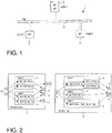
FIG. 1 shows asystem 1 comprising threenodes 3 labeled as "node 1", "node 2" and "node 3", respectively, and which are connected to acommunication channel 5 labeled as "bus". The bus is used for data communication between thenodes 3. The nodes are electronic devices which are in some fields of application, such as the automotive industry, referred to as electronic control units (ECU). Each node may include a dedicated piece of hardware which interfaces the node with the communication channel and which is then commonly referred to as a controller. In the example illustrated inFIG. 1 , the communication channel is embodied as a bus having broadcasting semantics which means that data transmitted to the communication channel from one of the nodes may be received by any of the other nodes. The present invention is, however, not limited to such a communication channel but encompasses also communication channels of other suitable topology and semantics. -
System 1 is configured to execute software which is composed of several modules M1, M2, M3 and M4. Modules are an example of a method of structuring complex software, and a module generally is a piece of software having an application programming interface (API). Software which is composed of plural modules allows transparent distribution of the software over plural nodes for executing the software. In the example illustrated inFIG. 1 ,node 1 executes modules M1 and M2,node 2 executes module M3 andnode 3 executes module M4. - A more specific example of software composed of two modules is illustrated in
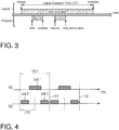
FIG. 2 . The exemplary software shown inFIG. 2 comprises a first module 7 labeled as "Module Service" and a second module 8 labeled as "Module Client". Each module may comprise a set of sensors 9, a set ofactuators 10 and a set ofmodes 11. The sensors 9 of module 7 are labeled "S1", "S2", and the sensor 9 of module 8 is labeled "S". Theactuators 10 of module 7 are labeled as "A1", "A2" and "A3", and theactuators 10 of the module 8 are labeled as "A1" and "A2". Module 7 has twomodes 11, labeled as "mode 1" and "mode 2". Module 8 has threemodes 11, labeled as "mode 1", "mode 2" and "mode 3". - Each module 7, 8 may be in only one mode at a given time.
Mode 1 of module 7 comprises two tasks labeled as "task 1" and "task 2", whereintask 1 is repetitively executed at a first period of ten milliseconds as indicated by "[10 ms]", andtask 2 is repetitively executed at a period of twenty milliseconds indicated by "[20 ms]". - In the present example, task invocations might adhere to the LET semantics as introduced by the Giotto programming model (see the article of T. A. Henzinger et al. mentioned in the introductory part). Task invocation according to LET is illustrated in the schematic diagram of
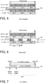
FIG. 3 . The inputs of the task are read at the beginning of a LET period. The reading of the inputs is practically done in close to zero time, what is called "logical zero time" (LZT). The beginning of the LET period is indicated by the arrow labeled "release" inFIG. 3 . Newly calculated outputs of the task are available exactly at the end of the LET period which is indicated by an arrow labeled "terminate" inFIG. 3 . The physical execution of the task on the node is started at a time indicated by an arrow labeled "start" and terminated at a time indicated by an arrow labeled "stop", wherein the physical execution of the task is suspended at a time indicated by an arrow labeled "suspend" and resumed at a time indicated by an arrow labeled "resume". - The time of physical execution within the LET period is not defined by LET. However, it is a requirement that the physical execution of the task has to finish before the end of the LET period. In other words, the start of the physical execution of the task can take place at or after the beginning of the LET period, and the end of the physical execution of the task has to occur at the latest, also for the worst case, before or at the end of the LET period. According to the LET semantics, the results of the calculation of the task are only available to the outside of the task at and after the end of the LET period rather than at the end of the physical execution of the task. This means, that before the end of the LET period, only the "old" results of the previous invocation of the task are available.
- Referring back to
FIG. 2 ,task 1 ofmode 1 of module 7 is repetitively executed at a period of ten milliseconds wherein the sensor is red exactly at the beginning of the ten-millisecond-period (in LZT) and wherein the results of the calculation oftask 1 are made available to actuator A1 exactly at the end of the ten-millisecond-period. -
FIG. 2 also illustrates communication between tasks. For example,task 1 inmode 1 of module 8 delivers its output as inputs totask 2 andtask 3. - Further,
FIG. 2 illustrates communication of tasks across module boundaries. An output oftask 2 ofmode 1 of module 7 is labeled as "task2.o" and is provided as an input totask 1 ofmode 1 of module 8. - The composition of the software of a set of modules and the definition of the tasks of the modules according to LET semantics allows transparent distribution of the software across one or plural nodes, wherein a temporal behavior of the software is guaranteed. In particular, adding a new module will never affect the observable temporal behavior of other modules as long as internal scheduling mechanisms of the respective nodes guarantee a conformance to LET, given that worst case execution times (WCET) and execution rates are known for all tasks.
-
FIG. 4 is an illustration of the execution of modules M1 and M2 bynode 1 shown inFIG. 1 . Module M1 has one task, "task 1", with LET1, and module M2 has one task, "task 2", with LET2.Task 2 uses the output oftask 1 as input, and LET1 oftask 1 is twice as large as LET2 oftask 2. The rectangles inFIG. 4 schematically indicate the physical execution times oftask 1 andtask 2. The outputs oftask 1 are made available totask 2 at the end of the logical execution time LET1 oftask 1 as indicated byarrow 13. This can be achieved by copying values from a location of memory associated withtask 1 to a location of memory associated withtask 2. Such copying will take close to zero time (logical zero time, LZT) on a single node. - Both the third and fourth invocations of
task 2 shown inFIG. 4 will use the output of the first invocation oftask 1. This means that the fourth invocation oftask 2 will not use the output of the second invocation oftask 1 even though physical execution of the second invocation oftask 1 is already completed when the physical execution of the fourth invocation oftask 2 begins. - It can be seen from the timing diagrams of
FIG. 4 that the concept of LET (logical execution time) makes task execution deterministic but also implies a task execution in every LET period. This might not be required for all tasks and thus would result in an inefficient usage of computing resources. This problem can be alleviated by the introduction of a novel feature called "slot selection" which will be explained in more detail below. - For the further explanation it is assumed that a mode period p is assigned to each mode (cf.
modes 11 ofFIG. 2 ) and a frequency number f is assigned to each task of the mode. The activity of a task is performed f times per mode period p. In case of a task invocation, the LET of the task is implicitly specified as p/f and the mode period is filled with f such task invocations. - The result of the above-mentioned description of the temporal behavior of the tasks according to the known Giotto language is illustrated in the timing diagrams of
FIG. 5 . For the following discussion a simple real-time system is considered as an example. The exemplary system has only one module including a single mode. Two tasks "task 1" and "task 2" are repeatedly executed within that mode, wherebytask 2 receives an output oftask 1 as an input. The mode period p is, for example, 120 ms (milliseconds) and the frequency f is 6. According, the Giotto language the result will be as shown inFIG. 5 , that istask 1 is executed six times per a mode period (LET1 = p/f = 120 ms/6 = 20 ms) andtask 2 is executed three times per mode period (LET2 = p/f = 120 ms/3 = 40 ms). The above definition of f and p implies that the duration of the mode period p is a common multiple of the LETs (LET1 and LED2 in the present example) of the tasks of the respective mode. Following the concept of LET, the first invocation oftask 2 uses, as an input, an initial value of the output oftask 1, the second invocation oftask 2 uses the output of the second invocation oftask 1, and the third invocation oftask 2 uses the output of the fourth invocation oftask 1. Thus, the output of the first, the third and the fifth invocation oftask 1 is discarded. One can see thattask 1 is executed redundantly as its output is not used for every invocation. The computation time consumed for the redundant task invocations can not be used for other tasks. As a consequence, the processor executing the code has to be designed for a load higher than actually necessary for the respective control application. - To alleviate this problem a method for defining the temporal behavior of a real-time system according to one example of the present invention allows for assigning the single task invocations to predefined time slots within the mode period p. In the above-discussed example it would be sufficient to execute task 1 (having a LET of 20 ms) only in the first, the third, and the fifth time slot of 20 ms, whereby the duration of a time slot is defined as p/f (the mode period divided by frequency, i.e. the duration of a time slot corresponds to the LET of the respective task). With the present example of the invention the LET of a task and the frequency f are decoupled and the software engineer may specify the time slots during which a task is to be executed and during which the processor is free to process other tasks. The corresponding timing diagram is illustrated in
FIG. 6 . Accordingly, the redundant execution of tasks may be beneficially avoided. In practice, it allows one to specify, for example, breaks between invocations or to define that a task should be invoked at the beginning or at the end of a mode period only. As another beneficial consequence, it may help the task scheduler to find a feasible schedule and it may reduce the latency in the data flow between invocations of communicating tasks. - In addition to the above-mentioned slot selection the novel features of "task splitting" and "task sequences" will be described below. They avoid the problem of over-sampling of tasks to meet control engineering requirements and thus they also alleviate the problem of inefficient usage of computing resources.
- One consequence resulting from the use of the Giotto language for defining the temporal behavior of real time systems is the dead time, that is the delay of a task until its results are available, which equals 100 percent of the sample time assigned to a specific task. This effect can be directly seen in
FIG. 3 ; irrespective of the time when the physical calculation has finished (position "stop" inFIG. 3 ), the output is not available before the LET of the respective task has elapsed. - It is well known in control theory that, as a rule of thumb, the reaction time of a (digital) controller should be within approximately ten percent of the sample time of a task in order to achieve stable controller behavior. Since, when employing the Giotto model, the reaction time equals exactly the sample time, a high degree of oversampling is required in order to achieve an acceptable result.
- Since this oversampling increases the processor load unnecessarily, an improved alternative to the Giotto model would be desirable. According to another example of the invention a method for defining the temporal behavior of real-time systems makes use of the concepts of "task splitting" and "task sequences" as explained below.
- A Giotto task is associated with a single external function that represents the body (i.e. its main routine) of the task. In contrast, according to one example of the present invention, a task may be associated with two external functions, i.e. the body of the task is "split" into
- (1) a long running function that requires a non-zero LET, and
- (2) a LZT function that executes in close to zero time.
- Thereby, the LZT function (output function) is called first at the LET start and provides the new output values in a very short time, i.e. in LZT. The long running function is executed during the LET and might prepare the internal state of the task by some advance calculations such that the next call of the LZT function can be done fast, i.e. in LZT. This can be utilized e.g. for digital controllers which need to evaluate a polynomial as the core of their implementation.
- The task splitting discussed above allows for performing an update of one or more actuators right after the call of the LZT function. This novel extension is referred to as a so-called "task sequence". A task sequence comprises a task invocation followed by a set of actuator updates. The actuator updates of a task sequence are carried out right after the outputs of the respective task are available, that is at the beginning of the LET if the task is split so that a LZT function is available.
- The concepts of task splitting and task sequencing are schematically illustrated in the timing diagram of
FIG. 7 . The diagram illustrates one invocation of a task labeled "task 1".Task 1 is split into a LZT task and a task called "advance calculation". Task1 reads sensor information at the beginning of the task's LET and, in contrast to known methods, updates the actuators in close to zero time, i.e. in LZT, instead of at the end of the LET. After the actuator update, calculations necessary for the next task invocation might be performed during the LET. For example, if the task has to evaluate a (discrete time) differential equation

- might be calculated in advance during a previous invocation of
task 1 and only one multiplication and one addition has to be calculated in the LZT task, that is
- By means of the above-discussed task splitting and task sequencing, digital controllers can be implemented without the unit delay which would be present when using the original LET as proposed by the Giotto language.
- Besides time-triggered (i.e. synchronous) tasks, there is often a need for executing event-triggered (i.e. asynchronous) activities as well. According to one example of the invention, the method for defining the temporal behavior of real time systems also considers asynchronous task invocations and actuator updates. An asynchronous activity sequence (i.e. the task invocation that might be followed by an actuator update) may be triggered by the occurrence of an event. Examples of events are: a hardware interrupt, an asynchronous timer, or a task output port update.
- A (non maskable) hardware interrupt may usually have the highest priority in the system and may be used, for example, for connecting the system with asynchronous input devices. It may even interrupt synchronous activities. However, the impact of hardware interrupts on the timing of synchronous activities should be minimized. In addition, it is assumed that a maskable interrupt may be switched off until the associated event is executed. This reduces the danger of denial of service due to a large number of interrupts.
- Further, a periodic asynchronous timer may also be used as a trigger for asynchronous task invocations. Such a timer is independent from the timer that drives the synchronous activities because it uses its own time base. An asynchronous timer may for example be used as a watchdog for monitoring the execution of the time-triggered operations.
- Updating a task output port may trigger an asynchronous task invocation. It is assumed that both a synchronous and an asynchronous port update may be used as a trigger event. In case of a synchronous port update, i.e. a port update performed during a time triggered activity, the TDL semantics takes care that the impact on the timing of the synchronous activities is minimized. Port update events may e.g. be used for limit monitoring or for change notifications.
- By integrating asynchronous activities into TDL, the TDL run-time system is able to provide the synchronization of the data flow between synchronous and asynchronous activities. It has been shown that a lock-free synchronization approach with a negligible impact on the timing of the time-triggered activities is possible with the semantics described below.
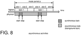
- Events may be associated with a priority and are registered in a priority queue when they arrive. Processing the events is delayed and supposed to be performed sequentially by a single background thread that runs whenever there are no time-triggered activities to perform as illustrated in
FIG. 8 . Reading input ports is done as part of the asynchronous execution, not at the time of registering an event. Output ports are updated right after an asynchronous task invocation has been finished. If an event reoccurs before it has started processing it will not be executed twice but remains registered once. In case of a distributed system, the communication of asynchronous output values to remote nodes is supposed to rely on asynchronous network operations, i.e. it may be delayed. - The technology and tools for generating platform-specific code are described, for example, in: "The TDL:VisualDistributor tool", preeTEC.com, available online: http://www.preetec.com/fileadmin/docs/Technology_Further_Docs/ TDL_VisualDistributor_March_2009.pdf.
- The TDL:VisualDistributor tool allows a developer (1) to define the topology and the particular properties of a specific platform, (2) to assign the TDL module(s) to the nodes of that platform by simply dragging and dropping TDL modules, and (3) to automatically generate the platform-specific code, in particular communication schedule(s) in case of distributed platforms and code for the run-time system, but also makefiles and any platform-specific files such as OIL-files in case of using the OSEK operating system. The TDL:VisualDistributor tool is implemented as plug-in architecture. Platform specific node-and cluster- plug-ins provide individual code- and communication schedule generators. Depending on the designated platform different sets of properties influence the code generation process.
Claims (7)
- A computer-based method for automatically constructing a real-time system with at least one module, each module having at least one mode, the method comprising:defining a mode period for each mode for a repeated execution of the respective mode by the corresponding module;for each mode, defining one or more synchronous tasks to be executed by the real-time system, whereby each synchronous task is associated with a logical execution time during which the task execution has to be completed;defining an integer number of time-slots for the mode period of each mode;assigning to each task at least one predefined and specifiable time slot during which the task is to be executed.
- The method of claim 1, whereby the length of each time slots equals the logic execution time of the task.
- The method of claim 1 or 2, further comprisingsplitting at least one task into a first part and a second part, the first part having a logical execution time shorter than the second part, whereby the first part is configured to calculate an output from at least one input and a pre-calculated data that is provided by the second part of a prior invocation of the task.
- The method of claim 3, whereby the first part of the task includes an output function, that is invocated on termination of the first part of the respective task.
- The method of one of the claims 1 to 4, further comprisingreceiving asynchronous events;assigning an asynchronous task to each received event;assigning a priority value to each asynchronous task;queuing the asynchronous tasks according to the priority value;scheduling the execution of the asynchronous tasks during periods when no synchronous task is executed.
- A computer-based system for the automatic design of real-time systems that include at least one module, each module having at least one mode, the system comprises:means configured to define a mode period for each mode for a repeated execution of the respective mode by the corresponding module;means configured to define, for each mode, one or more synchronous tasks to be executed by the real-time system, whereby each synchronous task is associated with a logical execution time during which the task execution has to be completed;means configured to define an integer number of time-slots for the mode period of each mode;means configured to assign to each task at least one predefined and specifiable time slot during which the task is to be executed.
- A computer program stored on an information processing device, the computer program including instructions which, upon execution by the information processing device, carry out one of the methods of claims 1 to 5.
Applications Claiming Priority (1)
| Application Number | Priority Date | Filing Date | Title |
|---|---|---|---|
| DE102009025572A DE102009025572A1 (en) | 2009-06-19 | 2009-06-19 | A method for developing guaranteed real-time systems |
Publications (2)
| Publication Number | Publication Date |
|---|---|
| EP2278454A1 EP2278454A1 (en) | 2011-01-26 |
| EP2278454B1 true EP2278454B1 (en) | 2017-01-11 |
Family
ID=42989247
Family Applications (1)
| Application Number | Title | Priority Date | Filing Date |
|---|---|---|---|
| EP10166520.6A Active EP2278454B1 (en) | 2009-06-19 | 2010-06-18 | Method for correct-by-construction development of real-time-systems |
Country Status (3)
| Country | Link |
|---|---|
| US (1) | US20100325635A1 (en) |
| EP (1) | EP2278454B1 (en) |
| DE (1) | DE102009025572A1 (en) |
Families Citing this family (5)
| Publication number | Priority date | Publication date | Assignee | Title |
|---|---|---|---|---|
| EP2375326A1 (en) * | 2010-04-08 | 2011-10-12 | Siemens Aktiengesellschaft | Executing operations via asynchronous programming model |
| EP2591416A4 (en) * | 2010-07-05 | 2014-08-13 | Saab Ab | Method for configuring a distributed avionics control system |
| US9699124B2 (en) * | 2014-05-08 | 2017-07-04 | Avaya Inc. | On-demand robot acquisition of communication features |
| CN109614239A (en) * | 2018-12-12 | 2019-04-12 | 浪潮(北京)电子信息产业有限公司 | System cluster load-balancing method, device and relevant device |
| CN111258754A (en) * | 2020-01-09 | 2020-06-09 | 上海依图信息技术有限公司 | Resource processing method, device, medium and system based on time window |
Family Cites Families (16)
| Publication number | Priority date | Publication date | Assignee | Title |
|---|---|---|---|---|
| EP0257655B1 (en) * | 1986-08-28 | 1994-07-06 | Nec Corporation | Multitask processing apparatus |
| ATE180586T1 (en) * | 1990-11-13 | 1999-06-15 | Ibm | PARALLEL ASSOCIATIVE PROCESSOR SYSTEM |
| US5978571A (en) * | 1993-03-19 | 1999-11-02 | Digital Equipment Corporation | Method and apparatus for synchronous circuit simulation design by eliminating unneeded timing behaviors prior to simulation run-time |
| US5612866A (en) * | 1994-06-24 | 1997-03-18 | Integrated Systems, Inc. | Code generation system to construct an asynchronous real-time controller for a real-time system |
| JP3645346B2 (en) * | 1996-01-22 | 2005-05-11 | 富士通株式会社 | Logic simulation device |
| US6438573B1 (en) * | 1996-10-09 | 2002-08-20 | Iowa State University Research Foundation, Inc. | Real-time programming method |
| US6360243B1 (en) * | 1998-03-10 | 2002-03-19 | Motorola, Inc. | Method, device and article of manufacture for implementing a real-time task scheduling accelerator |
| US6430593B1 (en) * | 1998-03-10 | 2002-08-06 | Motorola Inc. | Method, device and article of manufacture for efficient task scheduling in a multi-tasking preemptive priority-based real-time operating system |
| US6292841B1 (en) * | 1998-04-29 | 2001-09-18 | Xerox Corporation | Machine control using a ReferenceClock construct |
| US6964048B1 (en) * | 1999-04-14 | 2005-11-08 | Koninklijke Philips Electronics N.V. | Method for dynamic loaning in rate monotonic real-time systems |
| US6401005B1 (en) * | 1999-09-27 | 2002-06-04 | Rockwell Automation Technologies, Inc. | Programmable synchronous and asynchronous block execution for a computer numerical control |
| US6510361B1 (en) * | 2000-01-28 | 2003-01-21 | Rockwell Automation Technologies, Inc. | Computer numerical control utilizing synchronized logic execution in an open computer platform |
| US7234126B2 (en) * | 2000-08-23 | 2007-06-19 | Interuniversitair Microelektronica Centrum | Task concurrency management design method |
| JP4580845B2 (en) * | 2005-08-24 | 2010-11-17 | パナソニック株式会社 | Task execution device |
| US7428465B2 (en) * | 2006-01-26 | 2008-09-23 | Honeywell International Inc. | Testing control methods for use in current management systems for digital logic devices |
| GB2443277B (en) * | 2006-10-24 | 2011-05-18 | Advanced Risc Mach Ltd | Performing diagnostics operations upon an asymmetric multiprocessor apparatus |
-
2009
- 2009-06-19 DE DE102009025572A patent/DE102009025572A1/en not_active Ceased
-
2010
- 2010-06-16 US US12/802,897 patent/US20100325635A1/en not_active Abandoned
- 2010-06-18 EP EP10166520.6A patent/EP2278454B1/en active Active
Non-Patent Citations (1)
| Title |
|---|
| None * |
Also Published As
| Publication number | Publication date |
|---|---|
| US20100325635A1 (en) | 2010-12-23 |
| EP2278454A1 (en) | 2011-01-26 |
| DE102009025572A1 (en) | 2010-12-23 |
Similar Documents
| Publication | Publication Date | Title |
|---|---|---|
| Davare et al. | Period optimization for hard real-time distributed automotive systems | |
| Sifakis et al. | Building models of real-time systems from application software | |
| GB2425628A (en) | Programming distributed system using data flow diagrams | |
| Pop et al. | Analysis and optimization of distributed real-time embedded systems | |
| EP3364296B1 (en) | Simulating execution-time variations and scheduling in a block-oriented simulation system | |
| EP2278454B1 (en) | Method for correct-by-construction development of real-time-systems | |
| Cordovilla et al. | Developing critical embedded systems on multicore architectures: the Prelude-SchedMCore toolset | |
| Cervin et al. | Jitterbug and TrueTime: Analysis tools for real-time control systems | |
| US8543366B2 (en) | Simulating real-time software components based on logical execution time | |
| Henzinger et al. | Schedule-carrying code | |
| Dietrich et al. | Syswcet: Whole-system response-time analysis for fixed-priority real-time systems (outstanding paper) | |
| Henzinger et al. | Time-safety checking for embedded programs | |
| US20120310620A1 (en) | Method and system for simulation of real-time systems using access points | |
| Lemerre et al. | An introduction to time-constrained automata | |
| Glonina et al. | On the correctness of real-time modular computer systems modeling with stopwatch automata networks | |
| Zou et al. | PtidyOS: A lightweight microkernel for Ptides real-time systems | |
| Caspi et al. | From control loops to real-time programs | |
| Nahas et al. | Ways for implementing highly-predictable embedded systems using time-triggered co-operative (TTC) architectures | |
| Wan et al. | A time-aware programming framework for constructing predictable real-time systems | |
| Årzén et al. | Implementation-aware embedded control systems | |
| Bletsas | Worst-case and best-case timing analysis for real-time embedded systems with limited parallelism | |
| Fersman | A generic approach to schedulability analysis of real-time systems | |
| Lee et al. | Motivating time as a first class entity | |
| Fidge | Real-time scheduling theory | |
| Pree et al. | TDL-Steps Beyond Giotto: A Case for Automated Software Construction. |
Legal Events
| Date | Code | Title | Description |
|---|---|---|---|
| PUAI | Public reference made under article 153(3) epc to a published international application that has entered the european phase |
Free format text: ORIGINAL CODE: 0009012 |
|
| AK | Designated contracting states |
Kind code of ref document: A1 Designated state(s): AL AT BE BG CH CY CZ DE DK EE ES FI FR GB GR HR HU IE IS IT LI LT LU LV MC MK MT NL NO PL PT RO SE SI SK SM TR |
|
| AX | Request for extension of the european patent |
Extension state: BA ME RS |
|
| 17P | Request for examination filed |
Effective date: 20110720 |
|
| 17Q | First examination report despatched |
Effective date: 20150720 |
|
| GRAP | Despatch of communication of intention to grant a patent |
Free format text: ORIGINAL CODE: EPIDOSNIGR1 |
|
| INTG | Intention to grant announced |
Effective date: 20160725 |
|
| GRAS | Grant fee paid |
Free format text: ORIGINAL CODE: EPIDOSNIGR3 |
|
| GRAA | (expected) grant |
Free format text: ORIGINAL CODE: 0009210 |
|
| AK | Designated contracting states |
Kind code of ref document: B1 Designated state(s): AL AT BE BG CH CY CZ DE DK EE ES FI FR GB GR HR HU IE IS IT LI LT LU LV MC MK MT NL NO PL PT RO SE SI SK SM TR |
|
| REG | Reference to a national code |
Ref country code: GB Ref legal event code: FG4D |
|
| REG | Reference to a national code |
Ref country code: CH Ref legal event code: EP |
|
| REG | Reference to a national code |
Ref country code: AT Ref legal event code: REF Ref document number: 861850 Country of ref document: AT Kind code of ref document: T Effective date: 20170115 |
|
| REG | Reference to a national code |
Ref country code: IE Ref legal event code: FG4D |
|
| REG | Reference to a national code |
Ref country code: DE Ref legal event code: R096 Ref document number: 602010039463 Country of ref document: DE |
|
| REG | Reference to a national code |
Ref country code: LT Ref legal event code: MG4D |
|
| REG | Reference to a national code |
Ref country code: NL Ref legal event code: MP Effective date: 20170111 |
|
| REG | Reference to a national code |
Ref country code: AT Ref legal event code: MK05 Ref document number: 861850 Country of ref document: AT Kind code of ref document: T Effective date: 20170111 |
|
| REG | Reference to a national code |
Ref country code: FR Ref legal event code: PLFP Year of fee payment: 8 |
|
| PG25 | Lapsed in a contracting state [announced via postgrant information from national office to epo] |
Ref country code: NL Free format text: LAPSE BECAUSE OF FAILURE TO SUBMIT A TRANSLATION OF THE DESCRIPTION OR TO PAY THE FEE WITHIN THE PRESCRIBED TIME-LIMIT Effective date: 20170111 |
|
| PG25 | Lapsed in a contracting state [announced via postgrant information from national office to epo] |
Ref country code: HR Free format text: LAPSE BECAUSE OF FAILURE TO SUBMIT A TRANSLATION OF THE DESCRIPTION OR TO PAY THE FEE WITHIN THE PRESCRIBED TIME-LIMIT Effective date: 20170111 Ref country code: IS Free format text: LAPSE BECAUSE OF FAILURE TO SUBMIT A TRANSLATION OF THE DESCRIPTION OR TO PAY THE FEE WITHIN THE PRESCRIBED TIME-LIMIT Effective date: 20170511 Ref country code: NO Free format text: LAPSE BECAUSE OF FAILURE TO SUBMIT A TRANSLATION OF THE DESCRIPTION OR TO PAY THE FEE WITHIN THE PRESCRIBED TIME-LIMIT Effective date: 20170411 Ref country code: FI Free format text: LAPSE BECAUSE OF FAILURE TO SUBMIT A TRANSLATION OF THE DESCRIPTION OR TO PAY THE FEE WITHIN THE PRESCRIBED TIME-LIMIT Effective date: 20170111 Ref country code: GR Free format text: LAPSE BECAUSE OF FAILURE TO SUBMIT A TRANSLATION OF THE DESCRIPTION OR TO PAY THE FEE WITHIN THE PRESCRIBED TIME-LIMIT Effective date: 20170412 Ref country code: LT Free format text: LAPSE BECAUSE OF FAILURE TO SUBMIT A TRANSLATION OF THE DESCRIPTION OR TO PAY THE FEE WITHIN THE PRESCRIBED TIME-LIMIT Effective date: 20170111 |
|
| PG25 | Lapsed in a contracting state [announced via postgrant information from national office to epo] |
Ref country code: SE Free format text: LAPSE BECAUSE OF FAILURE TO SUBMIT A TRANSLATION OF THE DESCRIPTION OR TO PAY THE FEE WITHIN THE PRESCRIBED TIME-LIMIT Effective date: 20170111 Ref country code: PL Free format text: LAPSE BECAUSE OF FAILURE TO SUBMIT A TRANSLATION OF THE DESCRIPTION OR TO PAY THE FEE WITHIN THE PRESCRIBED TIME-LIMIT Effective date: 20170111 Ref country code: ES Free format text: LAPSE BECAUSE OF FAILURE TO SUBMIT A TRANSLATION OF THE DESCRIPTION OR TO PAY THE FEE WITHIN THE PRESCRIBED TIME-LIMIT Effective date: 20170111 Ref country code: BG Free format text: LAPSE BECAUSE OF FAILURE TO SUBMIT A TRANSLATION OF THE DESCRIPTION OR TO PAY THE FEE WITHIN THE PRESCRIBED TIME-LIMIT Effective date: 20170411 Ref country code: AT Free format text: LAPSE BECAUSE OF FAILURE TO SUBMIT A TRANSLATION OF THE DESCRIPTION OR TO PAY THE FEE WITHIN THE PRESCRIBED TIME-LIMIT Effective date: 20170111 Ref country code: LV Free format text: LAPSE BECAUSE OF FAILURE TO SUBMIT A TRANSLATION OF THE DESCRIPTION OR TO PAY THE FEE WITHIN THE PRESCRIBED TIME-LIMIT Effective date: 20170111 Ref country code: PT Free format text: LAPSE BECAUSE OF FAILURE TO SUBMIT A TRANSLATION OF THE DESCRIPTION OR TO PAY THE FEE WITHIN THE PRESCRIBED TIME-LIMIT Effective date: 20170511 |
|
| REG | Reference to a national code |
Ref country code: DE Ref legal event code: R097 Ref document number: 602010039463 Country of ref document: DE |
|
| PG25 | Lapsed in a contracting state [announced via postgrant information from national office to epo] |
Ref country code: SK Free format text: LAPSE BECAUSE OF FAILURE TO SUBMIT A TRANSLATION OF THE DESCRIPTION OR TO PAY THE FEE WITHIN THE PRESCRIBED TIME-LIMIT Effective date: 20170111 Ref country code: EE Free format text: LAPSE BECAUSE OF FAILURE TO SUBMIT A TRANSLATION OF THE DESCRIPTION OR TO PAY THE FEE WITHIN THE PRESCRIBED TIME-LIMIT Effective date: 20170111 Ref country code: CZ Free format text: LAPSE BECAUSE OF FAILURE TO SUBMIT A TRANSLATION OF THE DESCRIPTION OR TO PAY THE FEE WITHIN THE PRESCRIBED TIME-LIMIT Effective date: 20170111 Ref country code: RO Free format text: LAPSE BECAUSE OF FAILURE TO SUBMIT A TRANSLATION OF THE DESCRIPTION OR TO PAY THE FEE WITHIN THE PRESCRIBED TIME-LIMIT Effective date: 20170111 |
|
| PLBE | No opposition filed within time limit |
Free format text: ORIGINAL CODE: 0009261 |
|
| STAA | Information on the status of an ep patent application or granted ep patent |
Free format text: STATUS: NO OPPOSITION FILED WITHIN TIME LIMIT |
|
| PG25 | Lapsed in a contracting state [announced via postgrant information from national office to epo] |
Ref country code: DK Free format text: LAPSE BECAUSE OF FAILURE TO SUBMIT A TRANSLATION OF THE DESCRIPTION OR TO PAY THE FEE WITHIN THE PRESCRIBED TIME-LIMIT Effective date: 20170111 Ref country code: SM Free format text: LAPSE BECAUSE OF FAILURE TO SUBMIT A TRANSLATION OF THE DESCRIPTION OR TO PAY THE FEE WITHIN THE PRESCRIBED TIME-LIMIT Effective date: 20170111 |
|
| 26N | No opposition filed |
Effective date: 20171012 |
|
| PG25 | Lapsed in a contracting state [announced via postgrant information from national office to epo] |
Ref country code: MC Free format text: LAPSE BECAUSE OF FAILURE TO SUBMIT A TRANSLATION OF THE DESCRIPTION OR TO PAY THE FEE WITHIN THE PRESCRIBED TIME-LIMIT Effective date: 20170111 |
|
| REG | Reference to a national code |
Ref country code: CH Ref legal event code: PL |
|
| GBPC | Gb: european patent ceased through non-payment of renewal fee |
Effective date: 20170618 |
|
| PG25 | Lapsed in a contracting state [announced via postgrant information from national office to epo] |
Ref country code: SI Free format text: LAPSE BECAUSE OF FAILURE TO SUBMIT A TRANSLATION OF THE DESCRIPTION OR TO PAY THE FEE WITHIN THE PRESCRIBED TIME-LIMIT Effective date: 20170111 |
|
| REG | Reference to a national code |
Ref country code: IE Ref legal event code: MM4A |
|
| PG25 | Lapsed in a contracting state [announced via postgrant information from national office to epo] |
Ref country code: CH Free format text: LAPSE BECAUSE OF NON-PAYMENT OF DUE FEES Effective date: 20170630 Ref country code: LI Free format text: LAPSE BECAUSE OF NON-PAYMENT OF DUE FEES Effective date: 20170630 Ref country code: LU Free format text: LAPSE BECAUSE OF NON-PAYMENT OF DUE FEES Effective date: 20170618 Ref country code: GB Free format text: LAPSE BECAUSE OF NON-PAYMENT OF DUE FEES Effective date: 20170618 Ref country code: IE Free format text: LAPSE BECAUSE OF NON-PAYMENT OF DUE FEES Effective date: 20170618 |
|
| REG | Reference to a national code |
Ref country code: BE Ref legal event code: MM Effective date: 20170630 |
|
| REG | Reference to a national code |
Ref country code: FR Ref legal event code: PLFP Year of fee payment: 9 |
|
| PG25 | Lapsed in a contracting state [announced via postgrant information from national office to epo] |
Ref country code: BE Free format text: LAPSE BECAUSE OF NON-PAYMENT OF DUE FEES Effective date: 20170630 |
|
| PG25 | Lapsed in a contracting state [announced via postgrant information from national office to epo] |
Ref country code: MT Free format text: LAPSE BECAUSE OF NON-PAYMENT OF DUE FEES Effective date: 20170618 |
|
| PG25 | Lapsed in a contracting state [announced via postgrant information from national office to epo] |
Ref country code: HU Free format text: LAPSE BECAUSE OF FAILURE TO SUBMIT A TRANSLATION OF THE DESCRIPTION OR TO PAY THE FEE WITHIN THE PRESCRIBED TIME-LIMIT; INVALID AB INITIO Effective date: 20100618 |
|
| PG25 | Lapsed in a contracting state [announced via postgrant information from national office to epo] |
Ref country code: CY Free format text: LAPSE BECAUSE OF NON-PAYMENT OF DUE FEES Effective date: 20170111 |
|
| PG25 | Lapsed in a contracting state [announced via postgrant information from national office to epo] |
Ref country code: MK Free format text: LAPSE BECAUSE OF FAILURE TO SUBMIT A TRANSLATION OF THE DESCRIPTION OR TO PAY THE FEE WITHIN THE PRESCRIBED TIME-LIMIT Effective date: 20170111 |
|
| PG25 | Lapsed in a contracting state [announced via postgrant information from national office to epo] |
Ref country code: TR Free format text: LAPSE BECAUSE OF FAILURE TO SUBMIT A TRANSLATION OF THE DESCRIPTION OR TO PAY THE FEE WITHIN THE PRESCRIBED TIME-LIMIT Effective date: 20170111 |
|
| PG25 | Lapsed in a contracting state [announced via postgrant information from national office to epo] |
Ref country code: AL Free format text: LAPSE BECAUSE OF FAILURE TO SUBMIT A TRANSLATION OF THE DESCRIPTION OR TO PAY THE FEE WITHIN THE PRESCRIBED TIME-LIMIT Effective date: 20170111 |
|
| PGFP | Annual fee paid to national office [announced via postgrant information from national office to epo] |
Ref country code: FR Payment date: 20230622 Year of fee payment: 14 |
|
| PGFP | Annual fee paid to national office [announced via postgrant information from national office to epo] |
Ref country code: IT Payment date: 20230630 Year of fee payment: 14 |
|
| PGFP | Annual fee paid to national office [announced via postgrant information from national office to epo] |
Ref country code: DE Payment date: 20230724 Year of fee payment: 14 |