EP2278434A2 - Power supply device, and remote control device thereof - Google Patents
Power supply device, and remote control device thereof Download PDFInfo
- Publication number
- EP2278434A2 EP2278434A2 EP10170542A EP10170542A EP2278434A2 EP 2278434 A2 EP2278434 A2 EP 2278434A2 EP 10170542 A EP10170542 A EP 10170542A EP 10170542 A EP10170542 A EP 10170542A EP 2278434 A2 EP2278434 A2 EP 2278434A2
- Authority
- EP
- European Patent Office
- Prior art keywords
- power supply
- unit
- remote controller
- units
- power
- Prior art date
- Legal status (The legal status is an assumption and is not a legal conclusion. Google has not performed a legal analysis and makes no representation as to the accuracy of the status listed.)
- Withdrawn
Links
Images


Classifications
-
- G—PHYSICS
- G06—COMPUTING; CALCULATING OR COUNTING
- G06F—ELECTRIC DIGITAL DATA PROCESSING
- G06F1/00—Details not covered by groups G06F3/00 - G06F13/00 and G06F21/00
- G06F1/26—Power supply means, e.g. regulation thereof
-
- G—PHYSICS
- G06—COMPUTING; CALCULATING OR COUNTING
- G06F—ELECTRIC DIGITAL DATA PROCESSING
- G06F1/00—Details not covered by groups G06F3/00 - G06F13/00 and G06F21/00
- G06F1/26—Power supply means, e.g. regulation thereof
- G06F1/266—Arrangements to supply power to external peripherals either directly from the computer or under computer control, e.g. supply of power through the communication port, computer controlled power-strips
-
- G—PHYSICS
- G06—COMPUTING; CALCULATING OR COUNTING
- G06F—ELECTRIC DIGITAL DATA PROCESSING
- G06F1/00—Details not covered by groups G06F3/00 - G06F13/00 and G06F21/00
- G06F1/26—Power supply means, e.g. regulation thereof
- G06F1/32—Means for saving power
-
- G—PHYSICS
- G06—COMPUTING; CALCULATING OR COUNTING
- G06F—ELECTRIC DIGITAL DATA PROCESSING
- G06F13/00—Interconnection of, or transfer of information or other signals between, memories, input/output devices or central processing units
- G06F13/14—Handling requests for interconnection or transfer
Definitions
- the embodiments discussed herein are related to a power supply device for supplying power to electronic apparatuses, and a remote controller used for the power supply device.
- a certain aspect of the embodiments discussed herein is related to a power supply device for supplying electric power supplied from an external power supply to electronic apparatuses such as a personal computer (PC), a server, and a monitor.
- PC personal computer
- server server
- monitor monitor
- the power supply device may include power supply units 2 1 to 2 n (n is an arbitrary integer) which are supplied with power by an external power supply 1, and a personal computer (PC) 6 for remote control which is connected to the external power supply 1 via a hub 3, a communication line 4 such as the Internet, and a hub 5.
- PC personal computer
- LAN cables connect the power supply units 2 1 to 2 n and the hub 5 and the PC 6.
- the power supply units 2 1 to 2 n include plural ports 7 which distribute power supplied from the external power supply 1.
- the electronic apparatuses such as a PC, a server and a monitor are connected to the ports 7.
- the power supply units 2 1 to 2 n include built-in relays such as an electric relay which can connect and disconnect the ports 7 and the external power supply 1.
- the above-mentioned power supply device has the following problem related to the power supply from the ports 7 being controlled via the PC 6 by the operator.
- the PC 6 is ordinarily started up after an ordinary start-up time elapses.
- the power is not supplied from the power supply device, and the operator is obliged to wait until the PC 6 completely boots up.
- the power may not be immediately shut off when over-current is generated during the start-up time.
- the start-up time is on the order of minutes.
- the PC 6 is being constantly operated to enable the PC 6 to always control the power supply, the PC 6 itself consumes power even when the PC 6 does not control the power supply. Therefore, increases in the power consumption have been unavoidable. Even when the power supply has not been controlled by the PC 6, the PC 6 carries out virus scanning or the like. Therefore, power is consumed when the PC 6 is constantly turned on.
- the power supplied by the power supply device may momentarily exceed the maximal power which can be supplied by the power supply device.
- timings of turning on the electric relays of the ports 7 in the power supply units 2 1 to 2 n are not controlled.
- the object of the present embodiments is to provide a power supply device which can immediately supply power when necessary and a remote controller used for the power supply device.
- Another object of the present embodiments is to provide a power supply device which can control a timing of starting to supply power and a remote controller used for the power supply device.
- a power supply device including a power supply unit configured to switch supply or non-supply of power from an external power supply to an electronic apparatus, and a receiving unit configured to receive a control command for controlling the switching of the power supply unit using a remote controller.
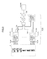
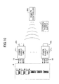
- FIG. 2 schematically illustrates an example configuration of a power supply device 10 of Embodiment 1.
- the power supply device 10 of Embodiment 1 includes power supply units 11 1 to 11 n and communication units 12 1 to 12 n functioning to receive power supply commands.
- the communication units 12 1 to 12 n are installed in the corresponding power supply units 11 1 to 11 n .
- n is an arbitrary integer and represents the unit numbers of the power supply units 11.
- the power supply units 11 1 to 11 n when the power supply units 11 1 to 11 n are not discriminated, the power supply units are representatively or collectively referred to as a power supply unit 11 or power supply units 11.
- the communication units 12 1 to 12 n when the communication units 12 1 to 12 n are not discriminated, the communication units are representatively or collectively referred to as a communication unit 12 or communication units 12.
- plural power supply units 11 and communication units 12 are illustrated in FIG. 2 , the numbers of the power supply units 11 and the communication units 12 may be at least one.
- the communication units 12 1 to 12 n may be installed inside or outside the power supply units 11 1 to 11 n .
- the power supply units 11 1 to 11 n include plural ports 14 which distribute power supplied from an external power supply 1.
- Electronic apparatuses 8 such as a PC, a server and a monitor are connected to the ports 14.
- the power supply units 11 1 to 11 n switch supply or non-supply of power supplied from the external power supply 1 to the electronic apparatuses 8.
- the number of the ports 14 is not limited to four and may be at least one.
- the communication units 12 1 to 12 n are connected to a remote controller 100 via LAN cables 13A, hubs 3 and 5, a communication line 4 such as the Internet, and a LAN cable 13B.
- the communication units 12 1 to 12 n function as interfaces which receive control commands for controlling switching of the power supply units 11 1 to 11 n from the remote controller 100.
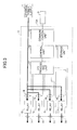
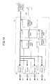
- An example internal configuration of the power supply unit 11 of Embodiment 1 is described below in reference to FIG. 3 .
- the remote controller 100 transmits the control command to the power supply device 10 of Embodiment 1. Detailed explanation of the remote controller 100 is given in reference to FIG. 5 later.
- the respective power supply units 11 include four relays 15 connected to the external power source 1.
- the ports 14 are connected on the output sides of the relays 15.
- the power supply unit 11 includes current sensors 16, an Input/Output (I/O) processing unit 17, a control unit 18, and a storage unit 19 in addition to the communication unit 12, the ports 14, and the relays 15.
- I/O Input/Output
- the current sensor 16 is an electric current detector which detects a current value supplied to the corresponding relay 15 from the external power supply 1. Signals indicative of the electric current values detected by the current sensors 16 are input to the control unit 18 via the I/O processing unit 17.
- the I/O processing unit 17 switches turning-on or turning-off of the relays 15 based on the control command input from the control unit 18, and inputs the current values detected by the respective current sensors 16 to the control unit 18.
- the control unit 18 mainly carries out a control process for driving the power supply unit 11.
- a central processing unit (CPU) may constitute the control unit 18.
- the control unit 18 carries out at least a process of generating the control command for controlling switching of the power supply unit 11 based on the control signal input from the remote controller 100 via the communication unit 12, and a process of comparing the current value input from the current sensors 16 via the I/O processing unit 17 with a predetermined value and detecting overcurrent.
- a CPU may constitute the control unit 18, the communication unit 12 and the I/O processing unit 17.
- the storage unit 19 stores data for driving the power supply unit 11.
- a nonvolatile memory may constitute the storage unit 19.
- IP Internet Protocol
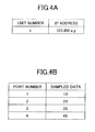
- FIG. 4A is a table schematically illustrating the IP address stored in the storage unit 19 of the power supply unit 11 of Embodiment 1.
- FIG. 4B is a table schematically illustrating the sampled data stored in the storage unit 19 of the power supply unit 11 of Embodiment 1.
- the IP address as the identification information of the power supply unit 11 and the sampled data may be partly or totally acquired from the power supply unit 11 via the communication unit 12.
- the IP address of the power supply units 11 1 to 11 n are allocated to the corresponding power supply units 11 1 to 11 n .
- the IP address inherent in the power supply unit 11 is stored in the storage unit 19 of the power supply unit 11 in association with the unit number as illustrated in FIG. 4A.
- FIG. 4A illustrates the IP address "123.456.x.y" (x and y are arbitrary numbers) of the power supply unit 11 k having the unit number k being an integer satisfying 1 ⁇ k ⁇ n.
- the sampled data are used for turning-on or turning-off of the four ports 14 of the power supply unit 11 identified by the IP address.
- the sampled data are included in the control command received from the remote controller 100.
- the sampled data include two digit numbers 1X, 2X, 3X and 4X respectively allocated to the first port, the second port, the third port and the fourth port 14.
- the tens places of the two digit numbers 1X, 2X, 3X and 4X designate the port number of the ports 14, and the ones places X of the two digit numbers 1X, 2X, 3X and 4X designate the port status. 0 or 1 is input as X. When the port 14 is turned off, 0 is input to X, and when the port 14 is turned on, 1 is input to X.
- the storage unit 19 of the power supply unit 11 stores the sampled data included in the control command received from the remote controller 100.
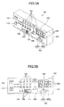
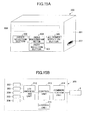
- FIG. 5A is a perspective view illustrating the remote controller 100 used in the power supply device 10 of Embodiment 1.
- FIG. 5B is a front view illustrating the remote controller 100 used in the power supply device 10 of Embodiment 1.
- FIG. 5C is a block diagram illustrating an inner configuration of the remote controller 100 used in the power supply device 10 of Embodiment 1.
- the remote controller 100 includes a casing 101, unit selection buttons 102 (102A, 102B) a display unit 103, port on/off buttons 104, a status indicating lamp 105, a display selection button 106, port indication lamps 107, unit indication lamps 108, a power lamp 109, an overcurrent warning lamp 110, and a hold switch 111.
- the casing 101 may have a plastic rectangular solid like body having a cavity in it.
- the unit selection buttons 102 (102A, 102B), the display unit 103, the port on/off buttons 104, the status indicating lamp 105, the display selection button 106, the port indication lamps 107, the unit indication lamps 108, the power lamp 109, the overcurrent warning lamp 110, and the hold switch 111 are exposed on the outside of the casing.
- the unit selection buttons 102 include a selection button 102A and a confirmation button 102B for selecting the power supply units 11 1 to 11 n .
- the selection button 102A is a pair of buttons shaped like triangles for selecting the unit number n of the power supply units 11 1 to 11 n .
- the unit number n selected with the selection button 102A is displayed on the display unit 103.
- the confirmation button 102B is provided to confirm the unit number n selected in the selection button 102A.
- a liquid crystal panel for displaying the unit number of the power supply unit 11 to be selected, and a voltage value, a current value, an output value and the like of the port 14 selected by the display selection button 106 constitutes the display unit 103.
- the port on/off buttons 104 are provided to turn on or off the four ports 14 of the power supply unit 11 selected by the unit selection button 102.
- the status indicating lamps 105 include four light emitting diodes (LED) corresponding to the four ports 14 of the power supply unit 11. The LED corresponding to the port which is turned on by the port on/off button 104 is lit.
- LED light emitting diodes
- the display selection button 106 is a button switch provided to select the port 14 for displaying the current value and the like on the display unit 103. It is possible to select the first port, the second port, the third port and the fourth port 14 in this order for every pressing of this button switch. When the display selection button 106 is pushed again while selecting the fourth port, it is possible to select a mode of displaying the sum of the current values of the first to fourth ports. When the display selection button 106 is pushed again after all of the first to fourth ports are selected, the first port can be selected.
- the port indication lamps 107 include four LEDs corresponding to the four ports 14 and an additional LED indicated by "TOTAL" in FIG. 5B and used when all of the four ports 14 are selected.
- the number of the LEDs for the port indication lamps 107 is five in FIG. 5A and 5B .
- the corresponding LED of the port indication lamps 107 is lit.
- the additional LED "TOTAL" of the port indication lamps 107 is lit.
- the unit indication lamps 108 may be LEDs for indicating units (V), (A) or (W) of the numbers displayed on the display unit 103 in order to indicate properties, i.e. voltage, current and output, of the numbers displayed on the display unit 103.
- the display on the display unit 103 may be automatically switched in the order of voltage, current and output by the control unit inside the remote controller 100.
- the unit indication lamps 108 are automatically switched over.
- the power lamp 109 is a LED indicating that the remote controller 100 is being charged.
- the power lamp 109 is lit when the remote controller 100 is charged via a power cord (not illustrated).
- the overcurrent warning lamp 110 is a LED which is lit when there is generation of overcurrent.
- the overcurrent warning lamp 110 is lit by the control unit inside the remote controller 100 when the overcurrent is detected by the control unit 18 of the power supply unit 11 and the remote controller 100 receives a signal indicative of the overcurrent from the power supply unit 11.
- the hold switch 111 is provided to switch between holding and non-holding in order to prevent operation of the remote controller 100. When the hold switch 111 is switched to holding, operation of the remote controller is not accepted.
- the remote controller 100 includes an I/O processing unit 112, a control unit 113, a communication unit 114, a storage unit 115, lamps 103, 105, 107, 108, 109 and 110 and switches 102, 104, 106 and 111.
- the lamps include the display unit 103, the status indicating lamp 105, the port indication lamp 107, the unit indication lamp 108, the power lamp 109 and the overcurrent warning lamp 110.
- the switches include the unit selection button 102(102A, 102B), the port on/off button 104, the display selection button 106 and the hold switch 111.
- the I/O processing unit 112 carries out a process of lighting the lamps and inputting signals indicative of input operations applied to the switches to the control unit 113 based on the command input from the control unit 113.
- the control unit 113 generates and outputs control commands corresponding to the input operations applied to the switches and the lighting of the lamps in response to the input operations.
- a CPU may constitute the control unit 113.
- the communication unit 114 outputs the control commands generated by the control unit 113.
- the communication unit 114 functions as an interface for transferring the control commands to the power supply unit 11 via the hub 5, the communication line 4 and the hub 3.
- a storage unit 115 may be a memory for storing the data indicative of the IP addresses of the power supply units 11 1 to 11 n and the port numbers 14.
- the storage unit may be a nonvolatile memory.
- the CPU may constitute the I/O processing unit 112, the control unit 113 and the communication unit 114.
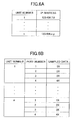
- FIG. 6A is a table schematically illustrating IP addresses stored in the storage unit 115 of the remote controller 100 of Embodiment 1.
- FIG. 6B is a table schematically illustrating sampled data stored in the storage unit 115 of the remote controller 100 of Embodiment 1.
- the IP addresses as the identification information of the power supply units 11 and the sampled data may be partly or totally acquired from the power supply units 11 via the communication units 12.
- the storage unit 115 of the remote controller 100 stores identification information such as the IP addresses of the power supply units 11 1 to 11 n in association with the unit numbers 1 to n.
- the sampled data are two digits numbers 1X, 2X, 3X and 4X allocated to the first to fourth ports 14 respectively for each of the power supply units 11.
- the sampled data illustrated in FIG. 6B include data about all of the ports of all of the power supply units 11 to be controlled by the remote controller 100.
- the signals indicative of the operations are input to the control unit 113.
- the control unit 113 sets 0 or 1 to X on the ones place of the sampled data corresponding to the designated unit number and the port number.
- the set sampled data are output from the communication unit 114 by the control unit 113 along with the data indicative of the unit number and the port number.
- FIG. 7 is a flowchart illustrating a transmission process of the control command with the remote controller 100 used for the power supply device 10 of Embodiment 1.
- the transmission process is carried out by the control unit 113 of the remote controller 100.
- the control unit 113 determines whether a unit number is input in step S1. Because a different IP address is allocated to a different unit number, a connection between the power supply unit 11 and the control unit 113 of the remote controller 100 is established after the IP address of the power supply unit 11 is identified. Step S1 is repeated until the unit number is input.
- control unit 113 When the unit number is input, the control unit 113 reads out an IP address associated with the input unit number from the database illustrated in FIG. 6A and stored in the storage unit 115, and the connection with the power supply unit 11 is established by the communication unit 114 in step S2.
- the control unit 113 determines whether the sampled data for selecting the port 14 are input in step S3. Step S3 is repeated until the sampled data are input.
- the control unit 113 generates a control command for turning on or off the relay corresponding to the port number indicated by the sampled number in step S4.
- the control unit 113 specifically generates a control command of turning off the relay 15 corresponding to the port number 1 when the sampled data is "10".
- the control unit 113 specifically generates a control command of turning on the relay 15 corresponding to the port number 1 when the sampled data is "11".
- the control unit 113 specifically generates a control command of turning off the relay 15 corresponding to the port number 2 when the sampled data is "20”.
- the control unit 113 specifically generates a control command of turning on the relay 15 corresponding to the port number 2 when the sampled data is "21".
- the control unit 113 specifically generates a control command of turning off the relay 15 corresponding to the port number 3 when the sampled data is "30".
- the control unit 113 specifically generates a control command of turning on the relay 15 corresponding to the port number 3 when the sampled data is "31”.
- the control unit 113 specifically generates a control command of turning off the relay 15 corresponding to the port number 4 when the sampled data is "40".
- the control unit 113 specifically generates a control command of turning on the relay 15 corresponding to the port number 4 when the sampled data is "41".
- the contents of the sampled data are included in the control commands.
- the control unit 113 orders the communication unit 114 to output the control commands generated in step S4, and stores the control commands in the storage unit 115 in step S5. Thus, the control commands are transmitted to the power supply units 11 identified by the unit numbers.
- step S5 After completing the step S5, the process goes back to step S1.
- control unit 113 The above-described process carried out by the control unit 113 is repeated while the power supply device 10 of Embodiment 1 is operated.
- FIG. 8 is a flowchart illustrating a process carried out by the control unit 18 inside the power supply unit 11 of the power supply device 10 of Embodiment 1. This process is carried out by the control unit 18 of the power supply unit 11, and repeated while the power supply unit 11 is operated.
- the control unit 18 determines whether the control command is received from the remote controller 100 in step S10. Step S10 is repeated until the control command is received.
- control unit 18 When the control command is received via the communication unit 12, the control unit 18 turns on or off the relay 15 corresponding to the port number identified by the control command in response to the sampled data contained in the control command in step S11.
- the control unit 18 specifically makes the I/O processing unit turn off the relay 15 corresponding to the port number 1 when the sampled data is "10".
- the control unit 18 specifically makes the I/O processing unit turn on the relay 15 corresponding to the port number 1 when the sampled data is "11".
- the control unit 18 specifically makes the I/O processing unit 17 turn off the relay 15 corresponding to the port number 2 when the sampled data is "20”.
- the control unit 18 specifically makes the I/O processing unit turn on the relay 15 corresponding to the port number 2 when the sampled data is "21”.
- the control unit 18 specifically makes the I/O processing unit turn off the relay 15 corresponding to the port number 3 when the sampled data is "30".
- the control unit 18 specifically makes the I/O processing unit turn on the relay 15 corresponding to the port number 3 when the sampled data is "31".
- the control unit 18 specifically makes the I/O processing unit turn off the relay 15 corresponding to the port number 4 when the sampled data is "40".
- the control unit 18 specifically makes the I/O processing unit turn on the relay 15 corresponding to the port number 4 when the sampled data is "41".
- the power supply device 10 of Embodiment 1 can turn on or off an arbitrary port 14 of an arbitrary power supply source 11 when an operator operates the remote controller 100.
- the remote controller 100 Since the remote controller 100 is connected to the power supply units 11 1 to 11 n via the hub 5, the communication line 4 and the hub 3 as illustrated in FIG. 2 , it is possible to rapidly operate the power supply units 11 1 to 11 n when necessary.
- the power supply units 11 1 to 11 n can be operated before the PC 6 can be started up.
- the remote controller 100 consumes power only when it is operated. Therefore, the power consumption is much lower than that of the PC 6 (illustrated in FIG. 1 ), and the total power consumption of the power supply device 10 can be drastically reduced.
- the PC 6 has been used to store data such as the IP addresses to identify the power supply unit, generate an operation command, and send the operation command in the power supply device illustrated in FIG. 1 .
- the remote controller 100 is used instead of the PC 6, the user does not have to wait during the start-up time to thereby greatly reduce the power consumption during the start-up time or the like.
- the communication line 4 is not limited to a cable and may be a telephone line, a power line, an optical fiber, a wireless LAN, satellite communications, or the like.
- connections between the power supply units 11 1 to 11 n and the hub 3 and the connection between the hub 5 and the remote controller 100 are not limited to the LAN cable 13A and 13B, and may be a wireless LAN.
- the remote controller 100 illustrated in FIG. 5A and FIG. 5B is used.
- the remote controller is not limited to this and may be a remote controller illustrated in FIG. 9A and FIG. 9B .
- FIG. 9A illustrates a simplified remote controller 110.
- the simplified remote controller 110 includes only a casing 101, a unit selection button 102 (102A, 102B), a display unit 103, a port on/off button 104, and a status indicating lamp 105.
- the simplified remote controller 110 can operate the power supply units 11 1 to 11 n in a manner similar to the remote controller 100.
- FIG. 9B illustrates a multifunctional remote controller 120.
- the multifunctional remote controller 120 includes a larger liquid crystal panel 103 with higher definition, a port selection button 121, and a ten key keypad 122.
- the multifunction remote controller 120 it is possible to operate the power supply units 11 1 to 11 in a manner similar to that in the remote controller 100, and further display the power consumption and the electricity charges on a display unit 103.
- FIG. 10 schematically illustrates an example configuration of a power supply device 20 of Embodiment 2.
- the power supply device 20 is different from the power supply device 10 of Embodiments 1 at a point that an infrared remote controller 200 is used.
- an infrared remote controller 200 is used.
- the same reference symbols are attached to elements the same as those of the power supply device 10, and explanations thereof are omitted. Differences from Embodiment 1 are mainly described next.
- the power supply device 20 of Embodiment 2 includes power supply units 21 1 to 21 n and receiving units 22 1 to 22 n .
- the receiving units 22 1 to 22 n are attached to the power supply units 21 1 to 21 n .
- n is an arbitrary integer and represents the unit numbers of the power supply units 21.
- the remote controller 200 used for the power supply device 20 of Embodiment 2 is configured to send a control command with infrared communication.
- FIG. 11 schematically illustrates an example configuration of a power supply unit 21 of Embodiment 2.
- the receiving unit 22 is connected to a control unit 18.
- the receiving unit 22 demodulates an infrared signal received from the remote controller 200, extracts the control command, and inputs the control command to the control unit 18.
- the control unit 18 turns on or off relays 15 with sampled data contained in the received control command in a manner similar to that in the control unit 18 of Embodiment 1.
- FIG. 12A is a perspective view of the remote controller 200 used for the power supply device of Embodiment 2.
- FIG. 12B is a block diagram illustrating an inner configuration of the remote controller 200 used in the power supply device 20 of Embodiment 2.
- the remote controller 200 includes a casing 201, a unit selection button 102 (102A,102B), a display unit 103, a port on/off button 104, a status indicating lamp 105, and an infrared transmitter 210.
- the remote controller 200 further includes an I/O processing unit 212, a control unit 213, a transmission processing unit 214, a storage unit 215, lamps 103 and 105, and switches 102 and 104.
- the I/O processing unit 212 carries out a process of lighting the lamps and inputting a signal indicative of input operations applied to the switches to the control unit 213.
- the lamps are the display unit 103 and the status indicating lamp 105.
- the switches are the unit selection button 102 (102A, 102B) and the port on/off button 104.
- the control unit 213 generates and outputs control commands in response to the input operations applied to the switches and lights the lamps in response to the input operations.
- a CPU may constitute the control unit 213.
- the transmission processing unit 214 superposes a signal indicative of the control command generated by the control unit 213 on a carrier wave, modulates the superposed signal and the carrier wave, and inputs the modulated signal to the infrared transmitter 210.
- a storage unit 215 may be a nonvolatile memory for storing data indicative of unit numbers of the power supply units 21 1 to 21 n and port numbers of the ports 14.
- the infrared transmitter 210 transmits an infrared signal input from the transmission processing unit 214 to an outside of the remote controller 200.
- the remote controller 200 superposes control signals indicative of the unit numbers and the port numbers which are input to the unit selection button 102 (102A, 102B) and the port on/off button 104 and turning-on or turning-off of the ports 14 (i.e. turning-on or turning-off of the relays 15 connected to the ports 14) on the carrier wave, and transmits the superposed signal and the carrier wave as the infrared signal from the infrared transmitter 210 to the power supply units 21.
- the power supply unit 21 which has received the infrared ray signal from the remote controller 200 turns on or off the relays 15 based on the sampled data acquired by demodulating the infrared ray.
- the power supply device 20 of Embodiment 2 can turn on or off an arbitrary port 14 of an arbitrary power supply source 21 when an operator operates the remote controller 200.
- the remote controller 200 can rapidly and always operate the power supply units 21 since the start-up time does not exist in the remote controller 200, unlike the PC 6 of the power supply device illustrated in FIG. 1 .
- the remote controller 200 consumes power only when it is operated. Therefore, the power consumption is much lower than that of the PC (illustrated in FIG. 1 ), and the total power consumption of the power supply device 20 can be drastically reduced.
- the infrared remote controller 200 of Embodiment 2 may be combined with the remote controller 100.
- the infrared remote controller 200 as the remote controller 100 is connected to the power supply units 21 via the LAN cables 13A and 13B.
- the remote controller 200 is detached from the LAN cables 13A and 13B and the power supply units 11 are directly controlled by infrared communication. Therefore, the operability is improved.
- FIG. 13 is a perspective view of the power supply unit 21 and the remote controller 200 of Embodiment 2 attached to the power supply unit 21 by a magnet.
- the casing of the power supply unit 21 is made of a material like iron which a magnet attracts, by attaching a sheet-like magnet 23 to a back side of the casing of the remote controller 200, the remote controller 200 attracts the power supply unit 21 with magnetic force.
- a wireless LAN may be used to transmit an IP address from the remote controller 200 to the power supply unit 21.
- Embodiment 3 having a configuration substantially the same as that of Embodiment 1 is described.
- the power supply device 30 of Embodiment 3 includes power supply units 31 1 to 31 n and communication units 32 1 to 32 n as a mode of a receiving unit.
- the communication units 32 1 to 32 n are installed inside the corresponding power supply units 31 1 to 31 n .
- n is an arbitrary integer and represents unit numbers of the power supply units 31.
- the power supply units 31 1 to 31 n are not discriminated, the power supply units are representatively or collectively referred to as a power supply unit 31 or power supply units 31.
- the communication units 32 1 to 32 n are not discriminated, the communication units are representatively or collectively referred to as a communication unit 32 or communication units 32.
- plural power supply units 31 and communication units 32 are illustrated in FIG. 2 , the numbers of the power supply units 31 and the communication units 32 may be at least one.
- the communication units 32 1 to 32 n may be installed inside or outside the power supply units 31 1 to 31 n .
- the power supply units 32 1 to 32 n include plural ports 34 which distribute power supplied from an external power supply 1.
- Electronic apparatuses 8 such as a PC, a server and a monitor are connected to the ports 34.
- the power supply units 31 1 to 31 n switch supply or non-supply of power supplied from the external power supply 1 to the electronic apparatuses 8.
- the number of the ports 34 is not limited to four and may be at least one.
- the communication units 32 1 to 32 n are connected to a remote controller 300 via LAN cables 13A, hubs 3 and 5, a communication line 4 such as the Internet, and a LAN cable 13B.
- the communication units 32 1 to 32 n function as interfaces which receive control commands for controlling switching of the power supply units 31 1 to 31 n from the remote controller 300.
- An example internal configuration of the power supply unit 31 of Embodiment 3 is described below in reference to FIG. 14 .
- the remote controller 300 transmits an order command to the power supply device 30 of Embodiment 3. Detailed explanation of the remote controller 300 is given in reference to FIG. 15 later.
- FIG. 14 schematically illustrates an example configuration of the power supply unit 31 of Embodiment 3.
- the respective power supply units 31 include four relays 35 connected to the external power source 1.
- the ports 34 are connected to the output sides of the relays 35.
- the power supply unit 31 includes a communication unit 32, the ports 34, the relays 35, an I/O processing unit 36, a serial port 37, a control unit 38, and a storage unit 39.
- the I/O processing unit 36 turns on or off the relays 35 based on an order command input from the control unit 38.
- the serial port 37 is provided to connect the remote controller 300 to the power supply unit 31 for transmitting an IP address and a MAC address to the remote controller 300 and registering the order of the power supply units 31 into the remote controller 300.
- the remote controller 300 is connected to the power supply unit 31 via a cable for serial communication such as RS232C.
- the control unit 38 mainly carries out a control process for driving the power supply unit 31.
- a central processing unit (CPU) may constitute the control unit 38.
- the control unit 38 transmits at least a power-on command in order to supply power to the power supply units 31 corresponding to the order command based on the order command input from the remote controller 300 via the communication unit 32.
- a CPU may constitute the control unit 38, the communication unit 32 and the I/O processing unit 36.
- the storage unit 39 stores data for driving the power supply unit 31.
- a nonvolatile memory may constitute the storage unit 39.
- the storage unit 39 stores at least Internet Protocol (IP) addresses for identifying the power supply units 32 1 to 32 n , Media Access Control (MAC) addresses, and an order command indicative of an order of connecting the four relays 35.
- IP Internet Protocol
- MAC Media Access Control
- FIG. 15A is a perspective view of the remote controller 300 used for the power supply device 30 of Embodiment 3.
- FIG. 15B is a block diagram illustrating an inner configuration of the remote controller 300 used in the power supply device 30 of Embodiment 3.
- the remote controller 300 includes a casing 301, an order registration button 304, an all power supply ON button 305, a liquid crystal display part 306 and a serial port 37.
- the casing 301 may have a plastic rectangular solid-like body having a cavity in it.
- the order selection button 302, the port selection button 303, the order registration button 304, the all power supply ON button 305, the liquid crystal display part 306, and the serial port 37 are exposed on the outside of the casing.
- the order selection button 302 is used to register an order of supplying power to the power supply units 31 while selecting the power supply units 31 in this order.
- the port selection button 303 is pushed by an operator for selecting the port numbers of the ports 34. Every pushing of the port selection button 303 sequentially switches the port numbers 1 to 4.
- the registration button 304 is pushed by the operator to register the order selected by the order selection button 302, or the port 34 selected by the port selection button 303.
- the order selected by the order selection button 302 is confirmed when the order registration button 304 is pushed.
- the all power supply ON button 305 is provided to be pushed by the operator when an order command is transmitted to the power supply unit 31 from the remote controller 300.
- the liquid crystal display part 306 is provided to display the order, the IP address, the MAC address, and the port number or the like of the power supply units 31.
- the serial port 37 is provided to connect the remote controller 300 to the power supply unit 31 for transmitting an IP address and a MAC address to the remote controller 300 and registering the order of the power supply units 31 into the remote controller 300.
- the remote controller 300 includes an I/O processing unit 312, a control unit 313, a communication unit 314, and a storage unit 315.
- the I/O processing unit 312 carries out inputting of a command indicative of pushing to the control unit 313, displaying on the liquid crystal display part 306 when the command indicative of a display content is transmitted from the control unit 313, and inputting to the control unit 313 when the IP address and the MAC address are input from the serial port 37.
- the control unit 313 carries out generation and output of commands corresponding to the input operations through the order registration button 304 and the all power supply ON button 305, generation of display content to be displayed on the liquid crystal display part 306, and storage of the IP addresses and the MAC addresses input from the serial port 37 into the storage unit 315.
- a CPU may constitute the control unit 313.
- the communication unit 314 functions as an interface for transferring the order commands generated by the control unit 313 to the power supply unit 31 via the hub 5, the communication line 4 and the hub 3.
- the storage unit 315 may be a memory for storing the data indicative of the IP addresses, the MAC addresses, and the port numbers of the power supply units 31 1 to 31 n .
- the storage unit 315 may be a nonvolatile memory.
- a CPU may constitute the I/O processing unit 312, the control unit 313 and the communication unit 314.
- FIG. 16 is a table schematically illustrating data stored in the storage unit 315 of the remote controller 300 of Embodiment 3.
- the IP addresses, the MAC addresses, and the port numbers of the power supply devices 31 1 , 31 k and 31 n are illustrated in FIG. 16 .
- k is an integer satisfying 1 ⁇ k ⁇ n.
- the IP addresses and the MAC addresses of the power supply units 31 1 to 31 n are allocated to the corresponding power supply units 31 1 to 31 n . Therefore, the storage unit 315 of the remote controller 300 stores the IP addresses, the MAC addresses and the port numbers that are mutually associated and arranged in the order of supplying the power as the database.
- the IP addresses and the MAC addresses are used for identifying one power supply unit out of the power supply units 31 1 to 31 n .
- the data indicative of the port numbers are used to control turning-on or turning-off of the four ports 34 of the power supply unit 31.
- the data indicative of the IP addresses, the MAC addresses, and the port numbers relate to and represent the order command.
- the data indicative of the port number relate to and represent a terminal order command.
- the terminal order command is contained in the order command.
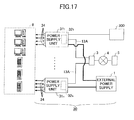
- FIG. 17 schematically illustrates an example configuration of the power supply unit 31 connected to the remote controller 300 of Embodiment 3.
- the remote controller 300 acquires the IP addresses and the MAC addresses of the power supply devices 31 1 while the remote controller 300 is connected to the power supply devices 31 1 .
- the serial port 307 (see FIG. 15B ) of the remote controller 300 and the serial port 37 (see FIG. 14 ) of the power supply devices 31 1 may be connected by a serial communication cable such as RS232C.
- the remote controller 300 acquires the IP addresses and the MAC addresses of the power supply devices 31 while the remote controller 300 is connected to the power supply unit 31, the order of supplying power of which is to be registered, among the power supply units 31 1 to 31 n .
- the IP addresses and the MAC addresses are arranged and registered in the order of supplying power in the remote controller 300.
- the order of the ports 34 is registered in addition to the order of the power supply units 31. By registering these ports and addresses, the data illustrated in FIG. 16 are obtainable.
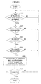
- FIG. 18 is a flowchart illustrating a process of registering the order of supplying power inside the remote controller 300 used for the power supply device 30 of Embodiment 3. The process is carried out by the control unit 313 of the remote controller 300.
- step S31 the control unit 313 determines whether the IP addresses and the MAC addresses are acquired from the power supply units 31. Step S31 is repeated until the IP addresses and the MAC addresses are acquired.
- step S32 the control unit 313 determines whether the port selection button is pushed and the port number is designated when the IP addresses and the MAC addresses are acquired from the power supply unit 31.
- the control unit 313 determines whether an order of selecting the ports 34 is selected in step S33.
- the selection of the order is carried out when the order selection button 303 illustrated in FIG. 15A is pushed.
- step S34 when the order is selected, the control unit 313 determines whether the order registration button 304 is pushed, and the order is confirmed.
- step S35 when the order is confirmed, the control unit 313 stores the IP addresses, the MAC addresses, and the port numbers in association with the order of selecting the ports in the storage unit 315.
- step S36 after the control unit 313 stores the IP addresses, the MAC addresses, and the port numbers in association with the order of selecting the ports in the storage unit 315, the control unit 313 determines whether another port 34 is to be registered.
- control unit 313 does not register the other ports 34 and determines the completion of the process, the process of steps S31 to S36 ends.
- control unit 313 selects NO in steps S31 to S34 and S36, the process returns to step S31.
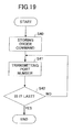
- FIG. 19 is a flowchart illustrating a process of the power-on based on the order command received by the power supply unit 31.
- the remote controller 300 is connected to the hub 5 as illustrated in FIG. 2 .
- the order command is transmitted to the power supply unit 31.
- a control unit 38 of the power supply unit 31 carries out the process illustrated in FIG. 19 .
- step S40 after the control unit 38 receives the order command, the control unit stores the order command in the storage unit 39.
- step S41 the control unit 38 sequentially reads out the order command stored in the storage unit 39, and transmits data indicative of the port number to one of the power supply units 31 1 to 31 n identified by the IP address and the MAC address.
- the control unit 38 turns on the relay 35 corresponding to the port number indicated by the transmitted data.
- step S42 the control unit 38 confirms whether there are the data of the next order. If there are the next data, the control unit repeats step S41. If there are not any next data, the control unit 38 completes the process. Thus, the process ends.
- steps S40 to S42 the data indicative of the port numbers are transmitted to one or more of the power supply unit 31 1 to 31 n in the order registered in the database illustrated in FIG. 16 generated in the remote controller 300.
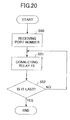
- FIG. 20 is a flowchart illustrating a process of supplying power carried out by the power supply unit 31 after the power supply unit 31 receives the port number. The process is carried out by the control unit 38 inside the power supply unit 31 which has received the port number.
- control unit 38 When the control unit 38 receives the port number in step S50, the control unit 38 connects the relay 35 corresponding to the port 34 indicated by the port number in step S51.
- step S52 the control unit 38 determines whether the last port number in the transmitted data is processed. If the final port number is processed, the process ends. If not, the process returns to step S51.
- the power is sequentially supplied from the four ports included in the power supply unit 31.
- the power supply device 30 of Embodiment 3 can easily register the order of supplying the power from the power supply unit 31 using the remote controller 300 in accordance with the process illustrated in FIG. 18 . Further, by registering the order of supplying the power in the power supply unit 31, it is possible to generate the database (see FIG. 16 ) for producing the order command.
- the power supply device 30 of Embodiment 3 can supply the power from the ports 34 of the power supply units 31 1 to 31 n to the electronic apparatuses (see FIG. 2 ) in the order registered in the database (see FIG. 16 ) by the process illustrated in FIG. 19 and FIG. 20 .
- the power supply units 31 1 to 31 n do not simultaneously start to supply power, and timings of starting to supply the power from the ports 34 inside the power supply units 31 1 to 31 n can be shifted. Therefore, it is possible to provide the power supply device which can stably supply power without generating a rush current.
- the order of supplying the power from the ports 34 may not be always registered.
- the power may be simultaneously started to be supplied from one or more of the ports 34, or the power may be supplied from the ports 34 in a predetermined order.
- the order command may be transmitted from the remote controller 300 to the power supply units 31 while the serial port 307 (see FIG. 15A and FIG. 15B ) of the remote controller 300 is connected to the serial port 37 (see FIG. 14 ) of the power supply unit 31 via a cable for serial communication.
- the power supply device 30 of Embodiment 3 can set the order of supplying the power without using the PC and can start to supply the power at any time without waiting through the start-up time as required in the power supply device using the PC 6 illustrated in FIG. 1 .
- the power supply device 10 of Embodiment 3 may include a PC in a similar manner to that in the power supply device using the PC 6 illustrated in FIG. 1 .
- the remote controller 300 may be connected to the PC, the database indicative of the order command may be stored in a memory of the PC, and the PC may carry out power supply sequentially in the above-described order.
- the power supply device 30 which transmits the order command from the remote controller 300 connected to the LAN cable 13B, it is also possible to transmit the order command between the power supply units 31 and the remote controller 300 via a wireless LAN instead of the LAN cable 13B.
- infrared communication may be used to transmit the order command between the remote controller 300 and the power supply units 31.
- Embodiments 1 to 3 it is possible to provide the power supply devices which can immediately control power supply when necessary and a remote controller used for the power supply device.
- the power supply device which can control a timing of starting to supply power and the remote controller used for the power supply device.
Abstract
A disclosed power supply device includes a power supply unit configured to switch supply or non-supply of power from an external power supply to an electronic apparatus, and a receiving unit configured to receive a control command for controlling the switching with the power supply unit from a remote controller.
Description
- This patent application is based upon and claims the benefit of priorities of the prior Japanese Patent Applications No.
2009-172518 filed on July 23, 2009 2009-172519 filed on July 23, 2009 - The embodiments discussed herein are related to a power supply device for supplying power to electronic apparatuses, and a remote controller used for the power supply device.
- A certain aspect of the embodiments discussed herein is related to a power supply device for supplying electric power supplied from an external power supply to electronic apparatuses such as a personal computer (PC), a server, and a monitor.
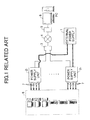
- For example, referring to
FIG. 1 , the power supply device may includepower supply units 21 to 2n (n is an arbitrary integer) which are supplied with power by anexternal power supply 1, and a personal computer (PC) 6 for remote control which is connected to theexternal power supply 1 via ahub 3, acommunication line 4 such as the Internet, and ahub 5. - Local area network (LAN) cables connect the
power supply units 21 to 2n and thehub 5 and the PC 6. - The
power supply units 21 to 2n includeplural ports 7 which distribute power supplied from theexternal power supply 1. The electronic apparatuses such as a PC, a server and a monitor are connected to theports 7. Thepower supply units 21 to 2n include built-in relays such as an electric relay which can connect and disconnect theports 7 and theexternal power supply 1. - When an operator inputs to the PC 6 to select one of the
power supply units 21 to 2n and one of itsports 7, a control command corresponding to the input is input to the selected power supply unit among thepower supply units 21 to 2n through the PC 6 and thecommunication line 4. Thus, the electric relay inside the power supply unit is connected to theport 7 identified by the control command. Then, power is supplied from theport 7 to theelectronic apparatus 8 such as the PC, the server and the monitor as described in Japanese Laid-open Patent Publication No.2-272954 2-183693 2-096444 - Meanwhile, the above-mentioned power supply device has the following problem related to the power supply from the
ports 7 being controlled via the PC 6 by the operator. - The PC 6 is ordinarily started up after an ordinary start-up time elapses. During the start-up time, the power is not supplied from the power supply device, and the operator is obliged to wait until the PC 6 completely boots up. For example, there is a case where the power may not be immediately shut off when over-current is generated during the start-up time.
For example, the start-up time is on the order of minutes. - Meanwhile, if the PC 6 is being constantly operated to enable the PC 6 to always control the power supply, the PC 6 itself consumes power even when the PC 6 does not control the power supply. Therefore, increases in the power consumption have been unavoidable. Even when the power supply has not been controlled by the PC 6, the PC 6 carries out virus scanning or the like. Therefore, power is consumed when the PC 6 is constantly turned on.
- In the above-mentioned power supply device, when all of the
power supply units 21 to 2n simultaneously start to supply power, the power supplied by the power supply device may momentarily exceed the maximal power which can be supplied by the power supply device. - Although it is possible to shift timings of turning on the electric relays of the
ports 7 in thepower supply units 21 to 2n, timings of starting to supply power with thepower supply units 21 to 2n are not controlled. - The object of the present embodiments is to provide a power supply device which can immediately supply power when necessary and a remote controller used for the power supply device.
- Another object of the present embodiments is to provide a power supply device which can control a timing of starting to supply power and a remote controller used for the power supply device.
- According to an aspect of the embodiment, there is provided a power supply device including a power supply unit configured to switch supply or non-supply of power from an external power supply to an electronic apparatus, and a receiving unit configured to receive a control command for controlling the switching of the power supply unit using a remote controller.
- The object and advantages of the embodiments will be realized and attained by means of the elements and combinations particularly pointed out in the appended claims. It is to be understood that both the foregoing general description and the following detailed description are exemplary and explanatory and are not restrictive of the invention as claimed.
-
-
FIG. 1 schematically illustrates an example configuration of a power supply device; -
FIG. 2 schematically illustrates an example configuration of a power supply device ofEmbodiments -
FIG. 3 schematically illustrates an example configuration of a power supply unit ofEmbodiment 1; -
FIG. 4A is a table schematically illustrating an IP address stored in a storage unit of the power supply unit ofEmbodiment 1; -
FIG. 4B is a table schematically illustrating sampled data stored in the storage unit of the power supply unit ofEmbodiment 1; -
FIG. 5A is a perspective view illustrating a remote controller used in the power supply device ofEmbodiment 1; -
FIG. 5B is a front view illustrating the remote controller used in the power supply device ofEmbodiment 1; -
FIG. 5C is a block diagram illustrating an inner configuration of the remote controller used in the power supply device ofEmbodiment 1; -
FIG. 6A is a table schematically illustrating IP addresses stored in a storage unit of the remote controller ofEmbodiment 1; -
FIG. 6B is a table schematically illustrating sampled data stored in a storage unit the remote controller ofEmbodiment 1; -
FIG. 7 is a flowchart illustrating a transmission process of a control command with the remote controller used for the power supply device ofEmbodiment 1; -
FIG. 8 is a flowchart illustrating a process carried out by thecontrol unit 18 inside the power supply unit of the power supply device ofEmbodiment 1; -
FIG. 9A is a front view of an example remote controller; -
FIG. 9B is a front view of another remote controller; -
FIG. 10 schematically illustrates an example configuration of a power supply device ofEmbodiment 2; -
FIG. 11 schematically illustrates an example configuration of a power supply unit ofEmbodiment 2; -
FIG. 12A is a perspective view of a remote controller used for the power supply device ofEmbodiment 2; -
FIG. 12B is a block diagram illustrating an inner configuration of the remote controller used in the power supply device ofEmbodiment 2; -
FIG. 13 is a perspective view of the power supply unit and the remote controller ofEmbodiment 2 attached to the power supply unit by a magnet; -
FIG. 14 schematically illustrates an example configuration of a power supply unit ofEmbodiment 3; -
FIG. 15A is a perspective view of a remote controller used for the power supply device ofEmbodiment 3; -
FIG. 15B is a block diagram illustrating an inner configuration of the remote controller used in the power supply device ofEmbodiment 3; -
FIG. 16 is a table schematically illustrating data stored in a storage unit of the remote controller ofEmbodiment 3; -
FIG. 17 schematically illustrates an example configuration of the power supply device ofEmbodiment 3; -
FIG. 18 is a flowchart illustrating a process of registering an order of supplying power inside the remote controller used for the power supply device ofEmbodiment 3; -
FIG. 19 is a flowchart illustrating a process of the power-on based on an order command received by the power supply unit; and -
FIG. 20 is a flowchart illustrating a process of the power-on after the power supply unit receives a port number. - Hereinafter, power supply devices and remote controllers used for the power supply devices of
Embodiments 1 to 3 are described with reference to accompanying drawings. -
FIG. 2 schematically illustrates an example configuration of apower supply device 10 ofEmbodiment 1. - The
power supply device 10 ofEmbodiment 1 includespower supply units 111 to 11n andcommunication units 121 to 12n functioning to receive power supply commands. Thecommunication units 121 to 12n are installed in the correspondingpower supply units 111 to 11n. In this, n is an arbitrary integer and represents the unit numbers of thepower supply units 11. - Hereinafter, when the
power supply units 111 to 11n are not discriminated, the power supply units are representatively or collectively referred to as apower supply unit 11 orpower supply units 11. In a similar manner, when thecommunication units 121 to 12n are not discriminated, the communication units are representatively or collectively referred to as acommunication unit 12 orcommunication units 12. Although pluralpower supply units 11 andcommunication units 12 are illustrated inFIG. 2 , the numbers of thepower supply units 11 and thecommunication units 12 may be at least one. Thecommunication units 121 to 12n may be installed inside or outside thepower supply units 111 to 11n. - The
power supply units 111 to 11n includeplural ports 14 which distribute power supplied from anexternal power supply 1.Electronic apparatuses 8 such as a PC, a server and a monitor are connected to theports 14. Thepower supply units 111 to 11n switch supply or non-supply of power supplied from theexternal power supply 1 to theelectronic apparatuses 8. The number of theports 14 is not limited to four and may be at least one. - The
communication units 121 to 12n are connected to aremote controller 100 viaLAN cables 13A,hubs communication line 4 such as the Internet, and aLAN cable 13B. Thecommunication units 121 to 12n function as interfaces which receive control commands for controlling switching of thepower supply units 111 to 11n from theremote controller 100. An example internal configuration of thepower supply unit 11 ofEmbodiment 1 is described below in reference toFIG. 3 . - The
remote controller 100 transmits the control command to thepower supply device 10 ofEmbodiment 1. Detailed explanation of theremote controller 100 is given in reference toFIG. 5 later. - Referring to
FIG. 3 , the respectivepower supply units 11 include fourrelays 15 connected to theexternal power source 1. Theports 14 are connected on the output sides of therelays 15. Thepower supply unit 11 includescurrent sensors 16, an Input/Output (I/O)processing unit 17, acontrol unit 18, and astorage unit 19 in addition to thecommunication unit 12, theports 14, and therelays 15. - The
current sensor 16 is an electric current detector which detects a current value supplied to the correspondingrelay 15 from theexternal power supply 1. Signals indicative of the electric current values detected by thecurrent sensors 16 are input to thecontrol unit 18 via the I/O processing unit 17. - The I/
O processing unit 17 switches turning-on or turning-off of therelays 15 based on the control command input from thecontrol unit 18, and inputs the current values detected by the respectivecurrent sensors 16 to thecontrol unit 18. - The
control unit 18 mainly carries out a control process for driving thepower supply unit 11. A central processing unit (CPU) may constitute thecontrol unit 18. Thecontrol unit 18 carries out at least a process of generating the control command for controlling switching of thepower supply unit 11 based on the control signal input from theremote controller 100 via thecommunication unit 12, and a process of comparing the current value input from thecurrent sensors 16 via the I/O processing unit 17 with a predetermined value and detecting overcurrent. - A CPU may constitute the
control unit 18, thecommunication unit 12 and the I/O processing unit 17. - The
storage unit 19 stores data for driving thepower supply unit 11. A nonvolatile memory may constitute thestorage unit 19. At least an Internet Protocol (IP) address for identifying one of thepower supply units 111 to 11n and sampled data for selecting the fourrelays 15 are stored in thestorage unit 19. -
FIG. 4A is a table schematically illustrating the IP address stored in thestorage unit 19 of thepower supply unit 11 ofEmbodiment 1.FIG. 4B is a table schematically illustrating the sampled data stored in thestorage unit 19 of thepower supply unit 11 ofEmbodiment 1. The IP address as the identification information of thepower supply unit 11 and the sampled data may be partly or totally acquired from thepower supply unit 11 via thecommunication unit 12.
The IP address of thepower supply units 111 to 11n are allocated to the correspondingpower supply units 111 to 11n. The IP address inherent in thepower supply unit 11 is stored in thestorage unit 19 of thepower supply unit 11 in association with the unit number as illustrated inFIG. 4A. FIG. 4A illustrates the IP address "123.456.x.y" (x and y are arbitrary numbers) of thepower supply unit 11k having the unit number k being an integer satisfying 1≤k≤n. - The sampled data are used for turning-on or turning-off of the four
ports 14 of thepower supply unit 11 identified by the IP address. The sampled data are included in the control command received from theremote controller 100. - The sampled data include two
digit numbers fourth port 14. The tens places of the twodigit numbers ports 14, and the ones places X of the twodigit numbers port 14 is turned off, 0 is input to X, and when theport 14 is turned on, 1 is input to X. Referring toFIG. 4B , thestorage unit 19 of thepower supply unit 11 stores the sampled data included in the control command received from theremote controller 100. -
FIG. 5A is a perspective view illustrating theremote controller 100 used in thepower supply device 10 ofEmbodiment 1.FIG. 5B is a front view illustrating theremote controller 100 used in thepower supply device 10 ofEmbodiment 1.FIG. 5C is a block diagram illustrating an inner configuration of theremote controller 100 used in thepower supply device 10 ofEmbodiment 1. - Referring to
FIG. 5A and FIG. 5B , theremote controller 100 includes acasing 101, unit selection buttons 102 (102A, 102B) adisplay unit 103, port on/offbuttons 104, astatus indicating lamp 105, adisplay selection button 106,port indication lamps 107,unit indication lamps 108, apower lamp 109, anovercurrent warning lamp 110, and ahold switch 111. - The
casing 101 may have a plastic rectangular solid like body having a cavity in it. The unit selection buttons 102 (102A, 102B), thedisplay unit 103, the port on/offbuttons 104, thestatus indicating lamp 105, thedisplay selection button 106, theport indication lamps 107, theunit indication lamps 108, thepower lamp 109, theovercurrent warning lamp 110, and thehold switch 111 are exposed on the outside of the casing. - The
unit selection buttons 102 include aselection button 102A and aconfirmation button 102B for selecting thepower supply units 111 to 11n. Theselection button 102A is a pair of buttons shaped like triangles for selecting the unit number n of thepower supply units 111 to 11n. The unit number n selected with theselection button 102A is displayed on thedisplay unit 103. Theconfirmation button 102B is provided to confirm the unit number n selected in theselection button 102A. - A liquid crystal panel for displaying the unit number of the
power supply unit 11 to be selected, and a voltage value, a current value, an output value and the like of theport 14 selected by thedisplay selection button 106 constitutes thedisplay unit 103. - The port on/off
buttons 104 are provided to turn on or off the fourports 14 of thepower supply unit 11 selected by theunit selection button 102. - The
status indicating lamps 105 include four light emitting diodes (LED) corresponding to the fourports 14 of thepower supply unit 11. The LED corresponding to the port which is turned on by the port on/offbutton 104 is lit. - The
display selection button 106 is a button switch provided to select theport 14 for displaying the current value and the like on thedisplay unit 103. It is possible to select the first port, the second port, the third port and thefourth port 14 in this order for every pressing of this button switch. When thedisplay selection button 106 is pushed again while selecting the fourth port, it is possible to select a mode of displaying the sum of the current values of the first to fourth ports. When thedisplay selection button 106 is pushed again after all of the first to fourth ports are selected, the first port can be selected. - The
port indication lamps 107 include four LEDs corresponding to the fourports 14 and an additional LED indicated by "TOTAL" inFIG. 5B and used when all of the fourports 14 are selected. The number of the LEDs for theport indication lamps 107 is five inFIG. 5A and 5B . When any one of the fourports 14 of thepower supply unit 11 is selected, the corresponding LED of theport indication lamps 107 is lit. When all of the fourports 14 of thepower supply unit 11 are selected, the additional LED "TOTAL" of theport indication lamps 107 is lit. - The
unit indication lamps 108 may be LEDs for indicating units (V), (A) or (W) of the numbers displayed on thedisplay unit 103 in order to indicate properties, i.e. voltage, current and output, of the numbers displayed on thedisplay unit 103. The display on thedisplay unit 103 may be automatically switched in the order of voltage, current and output by the control unit inside theremote controller 100. Theunit indication lamps 108 are automatically switched over. - The
power lamp 109 is a LED indicating that theremote controller 100 is being charged. Thepower lamp 109 is lit when theremote controller 100 is charged via a power cord (not illustrated). - The
overcurrent warning lamp 110 is a LED which is lit when there is generation of overcurrent. Theovercurrent warning lamp 110 is lit by the control unit inside theremote controller 100 when the overcurrent is detected by thecontrol unit 18 of thepower supply unit 11 and theremote controller 100 receives a signal indicative of the overcurrent from thepower supply unit 11. - The
hold switch 111 is provided to switch between holding and non-holding in order to prevent operation of theremote controller 100. When thehold switch 111 is switched to holding, operation of the remote controller is not accepted. - Referring to
FIG. 5C , theremote controller 100 includes an I/O processing unit 112, acontrol unit 113, acommunication unit 114, astorage unit 115,lamps - The lamps include the
display unit 103, thestatus indicating lamp 105, theport indication lamp 107, theunit indication lamp 108, thepower lamp 109 and theovercurrent warning lamp 110. The switches include the unit selection button 102(102A, 102B), the port on/offbutton 104, thedisplay selection button 106 and thehold switch 111. - The I/
O processing unit 112 carries out a process of lighting the lamps and inputting signals indicative of input operations applied to the switches to thecontrol unit 113 based on the command input from thecontrol unit 113. - The
control unit 113 generates and outputs control commands corresponding to the input operations applied to the switches and the lighting of the lamps in response to the input operations. A CPU may constitute thecontrol unit 113. - The
communication unit 114 outputs the control commands generated by thecontrol unit 113. Thecommunication unit 114 functions as an interface for transferring the control commands to thepower supply unit 11 via thehub 5, thecommunication line 4 and thehub 3. - A
storage unit 115 may be a memory for storing the data indicative of the IP addresses of thepower supply units 111 to 11n and the port numbers 14. The storage unit may be a nonvolatile memory. - The CPU may constitute the I/
O processing unit 112, thecontrol unit 113 and thecommunication unit 114. -
FIG. 6A is a table schematically illustrating IP addresses stored in thestorage unit 115 of theremote controller 100 ofEmbodiment 1.FIG. 6B is a table schematically illustrating sampled data stored in thestorage unit 115 of theremote controller 100 ofEmbodiment 1. The IP addresses as the identification information of thepower supply units 11 and the sampled data may be partly or totally acquired from thepower supply units 11 via thecommunication units 12. - Referring to
FIG. 6A , thestorage unit 115 of theremote controller 100 stores identification information such as the IP addresses of thepower supply units 111 to 11n in association with theunit numbers 1 to n. - Referring to
FIG. 6B , the sampled data are twodigits numbers fourth ports 14 respectively for each of thepower supply units 11. The sampled data illustrated inFIG. 6B include data about all of the ports of all of thepower supply units 11 to be controlled by theremote controller 100. - When the
remote controller 100 is operated to designate the unit number, the port number and turning-on or turning-off of theports 14, the signals indicative of the operations are input to thecontrol unit 113. Thecontrol unit 113sets communication unit 114 by thecontrol unit 113 along with the data indicative of the unit number and the port number. -
FIG. 7 is a flowchart illustrating a transmission process of the control command with theremote controller 100 used for thepower supply device 10 ofEmbodiment 1. The transmission process is carried out by thecontrol unit 113 of theremote controller 100. - The
control unit 113 determines whether a unit number is input in step S1. Because a different IP address is allocated to a different unit number, a connection between thepower supply unit 11 and thecontrol unit 113 of theremote controller 100 is established after the IP address of thepower supply unit 11 is identified. Step S1 is repeated until the unit number is input. - When the unit number is input, the
control unit 113 reads out an IP address associated with the input unit number from the database illustrated inFIG. 6A and stored in thestorage unit 115, and the connection with thepower supply unit 11 is established by thecommunication unit 114 in step S2. - The
control unit 113 determines whether the sampled data for selecting theport 14 are input in step S3. Step S3 is repeated until the sampled data are input. - The
control unit 113 generates a control command for turning on or off the relay corresponding to the port number indicated by the sampled number in step S4.
Thecontrol unit 113 specifically generates a control command of turning off therelay 15 corresponding to theport number 1 when the sampled data is "10". Thecontrol unit 113 specifically generates a control command of turning on therelay 15 corresponding to theport number 1 when the sampled data is "11". Thecontrol unit 113 specifically generates a control command of turning off therelay 15 corresponding to theport number 2 when the sampled data is "20". Thecontrol unit 113 specifically generates a control command of turning on therelay 15 corresponding to theport number 2 when the sampled data is "21". Thecontrol unit 113 specifically generates a control command of turning off therelay 15 corresponding to theport number 3 when the sampled data is "30". Thecontrol unit 113 specifically generates a control command of turning on therelay 15 corresponding to theport number 3 when the sampled data is "31". Thecontrol unit 113 specifically generates a control command of turning off therelay 15 corresponding to theport number 4 when the sampled data is "40". Thecontrol unit 113 specifically generates a control command of turning on therelay 15 corresponding to theport number 4 when the sampled data is "41". - The contents of the sampled data are included in the control commands.
- The
control unit 113 orders thecommunication unit 114 to output the control commands generated in step S4, and stores the control commands in thestorage unit 115 in step S5. Thus, the control commands are transmitted to thepower supply units 11 identified by the unit numbers. - After completing the step S5, the process goes back to step S1.
- The above-described process carried out by the
control unit 113 is repeated while thepower supply device 10 ofEmbodiment 1 is operated. -
FIG. 8 is a flowchart illustrating a process carried out by thecontrol unit 18 inside thepower supply unit 11 of thepower supply device 10 ofEmbodiment 1. This process is carried out by thecontrol unit 18 of thepower supply unit 11, and repeated while thepower supply unit 11 is operated. - The
control unit 18 determines whether the control command is received from theremote controller 100 in step S10. Step S10 is repeated until the control command is received. - When the control command is received via the
communication unit 12, thecontrol unit 18 turns on or off therelay 15 corresponding to the port number identified by the control command in response to the sampled data contained in the control command in step S11. - The
control unit 18 specifically makes the I/O processing unit turn off therelay 15 corresponding to theport number 1 when the sampled data is "10". Thecontrol unit 18 specifically makes the I/O processing unit turn on therelay 15 corresponding to theport number 1 when the sampled data is "11". Thecontrol unit 18 specifically makes the I/O processing unit 17 turn off therelay 15 corresponding to theport number 2 when the sampled data is "20". Thecontrol unit 18 specifically makes the I/O processing unit turn on therelay 15 corresponding to theport number 2 when the sampled data is "21". Thecontrol unit 18 specifically makes the I/O processing unit turn off therelay 15 corresponding to theport number 3 when the sampled data is "30". Thecontrol unit 18 specifically makes the I/O processing unit turn on therelay 15 corresponding to theport number 3 when the sampled data is "31". Thecontrol unit 18 specifically makes the I/O processing unit turn off therelay 15 corresponding to theport number 4 when the sampled data is "40". Thecontrol unit 18 specifically makes the I/O processing unit turn on therelay 15 corresponding to theport number 4 when the sampled data is "41". - As described, the
power supply device 10 ofEmbodiment 1 can turn on or off anarbitrary port 14 of an arbitrarypower supply source 11 when an operator operates theremote controller 100. - Since the
remote controller 100 is connected to thepower supply units 111 to 11n via thehub 5, thecommunication line 4 and thehub 3 as illustrated inFIG. 2 , it is possible to rapidly operate thepower supply units 111 to 11n when necessary. Thepower supply units 111 to 11n can be operated before thePC 6 can be started up. - Further, the
remote controller 100 consumes power only when it is operated. Therefore, the power consumption is much lower than that of the PC 6 (illustrated inFIG. 1 ), and the total power consumption of thepower supply device 10 can be drastically reduced. - The
PC 6 has been used to store data such as the IP addresses to identify the power supply unit, generate an operation command, and send the operation command in the power supply device illustrated inFIG. 1 . When theremote controller 100 is used instead of thePC 6, the user does not have to wait during the start-up time to thereby greatly reduce the power consumption during the start-up time or the like. - Further, in the power supply device illustrated in
FIG. 1 , there is ordinarily a risk such as an unauthorized access to the PC. In order to avoid a security matter, another way of not using the PC is favorable. According toEmbodiment 1, since it is possible to operate thepower supply unit 11 with theremote controller 100 without using the PC, the security matter caused in remotely controlling the PC does not occur. - Although a mode of connecting the
power supply units 111 to 11n to theremote controller 100 via thecommunication line 4 such as the Internet has been described above, thecommunication line 4 is not limited to a cable and may be a telephone line, a power line, an optical fiber, a wireless LAN, satellite communications, or the like. - The connections between the
power supply units 111 to 11n and thehub 3 and the connection between thehub 5 and theremote controller 100 are not limited to theLAN cable - In the above description, the
remote controller 100 illustrated inFIG. 5A and FIG. 5B is used. However, the remote controller is not limited to this and may be a remote controller illustrated inFIG. 9A and FIG. 9B . -
FIG. 9A illustrates a simplifiedremote controller 110. The simplifiedremote controller 110 includes only acasing 101, a unit selection button 102 (102A, 102B), adisplay unit 103, a port on/offbutton 104, and astatus indicating lamp 105. The simplifiedremote controller 110 can operate thepower supply units 111 to 11n in a manner similar to theremote controller 100. -
FIG. 9B illustrates a multifunctionalremote controller 120. The multifunctionalremote controller 120 includes a largerliquid crystal panel 103 with higher definition, aport selection button 121, and a tenkey keypad 122. In the multifunctionremote controller 120, it is possible to operate thepower supply units 111 to 11 in a manner similar to that in theremote controller 100, and further display the power consumption and the electricity charges on adisplay unit 103. -
FIG. 10 schematically illustrates an example configuration of apower supply device 20 ofEmbodiment 2. Thepower supply device 20 is different from thepower supply device 10 ofEmbodiments 1 at a point that an infraredremote controller 200 is used. Hereinafter, the same reference symbols are attached to elements the same as those of thepower supply device 10, and explanations thereof are omitted. Differences fromEmbodiment 1 are mainly described next. - The
power supply device 20 ofEmbodiment 2 includespower supply units 211 to 21n and receivingunits 221 to 22n. The receivingunits 221 to 22n are attached to thepower supply units 211 to 21n. In this, n is an arbitrary integer and represents the unit numbers of thepower supply units 21. - The
remote controller 200 used for thepower supply device 20 ofEmbodiment 2 is configured to send a control command with infrared communication. -
FIG. 11 schematically illustrates an example configuration of apower supply unit 21 ofEmbodiment 2. In thepower supply unit 21 ofEmbodiment 2, the receivingunit 22 is connected to acontrol unit 18.
The receivingunit 22 demodulates an infrared signal received from theremote controller 200, extracts the control command, and inputs the control command to thecontrol unit 18. Thecontrol unit 18 turns on or offrelays 15 with sampled data contained in the received control command in a manner similar to that in thecontrol unit 18 ofEmbodiment 1. -
FIG. 12A is a perspective view of theremote controller 200 used for the power supply device ofEmbodiment 2.FIG. 12B is a block diagram illustrating an inner configuration of theremote controller 200 used in thepower supply device 20 ofEmbodiment 2. - Referring to
FIG. 12A , theremote controller 200 includes acasing 201, a unit selection button 102 (102A,102B), adisplay unit 103, a port on/offbutton 104, astatus indicating lamp 105, and aninfrared transmitter 210. - Referring to
FIG. 12B , theremote controller 200 further includes an I/O processing unit 212, acontrol unit 213, atransmission processing unit 214, astorage unit 215,lamps - The I/
O processing unit 212 carries out a process of lighting the lamps and inputting a signal indicative of input operations applied to the switches to thecontrol unit 213. The lamps are thedisplay unit 103 and thestatus indicating lamp 105. The switches are the unit selection button 102 (102A, 102B) and the port on/offbutton 104. - The
control unit 213 generates and outputs control commands in response to the input operations applied to the switches and lights the lamps in response to the input operations. A CPU may constitute thecontrol unit 213. - The
transmission processing unit 214 superposes a signal indicative of the control command generated by thecontrol unit 213 on a carrier wave, modulates the superposed signal and the carrier wave, and inputs the modulated signal to theinfrared transmitter 210. - A
storage unit 215 may be a nonvolatile memory for storing data indicative of unit numbers of thepower supply units 211 to 21n and port numbers of theports 14. - The
infrared transmitter 210 transmits an infrared signal input from thetransmission processing unit 214 to an outside of theremote controller 200. - The
remote controller 200 superposes control signals indicative of the unit numbers and the port numbers which are input to the unit selection button 102 (102A, 102B) and the port on/offbutton 104 and turning-on or turning-off of the ports 14 (i.e. turning-on or turning-off of therelays 15 connected to the ports 14) on the carrier wave, and transmits the superposed signal and the carrier wave as the infrared signal from theinfrared transmitter 210 to thepower supply units 21. - The
power supply unit 21 which has received the infrared ray signal from theremote controller 200 turns on or off therelays 15 based on the sampled data acquired by demodulating the infrared ray. - As described, the
power supply device 20 ofEmbodiment 2 can turn on or off anarbitrary port 14 of an arbitrarypower supply source 21 when an operator operates theremote controller 200. - The
remote controller 200 can rapidly and always operate thepower supply units 21 since the start-up time does not exist in theremote controller 200, unlike thePC 6 of the power supply device illustrated inFIG. 1 . - Further, the
remote controller 200 consumes power only when it is operated. Therefore, the power consumption is much lower than that of the PC (illustrated inFIG. 1 ), and the total power consumption of thepower supply device 20 can be drastically reduced. - Further, in addition to the operation with the
PC 6 for remote control illustrated inFIG. 1 , there is a case where thePC 6 is directly connected to thepower supply units 2 illustrated inFIG. 1 and the relays are controlled to be turned on or off. When thePC 6 for remote control illustrated inFIG. 1 is not movable, another PC needs to be to directly connected with thepower supply unit 2. In this case, operability is insufficient. - The infrared
remote controller 200 ofEmbodiment 2 may be combined with theremote controller 100. In case of the remote control, the infraredremote controller 200 as theremote controller 100 is connected to thepower supply units 21 via theLAN cables remote controller 200 is detached from theLAN cables power supply units 11 are directly controlled by infrared communication. Therefore, the operability is improved. -
FIG. 13 is a perspective view of thepower supply unit 21 and theremote controller 200 ofEmbodiment 2 attached to thepower supply unit 21 by a magnet. - When the casing of the
power supply unit 21 is made of a material like iron which a magnet attracts, by attaching a sheet-like magnet 23 to a back side of the casing of theremote controller 200, theremote controller 200 attracts thepower supply unit 21 with magnetic force. - Although there has been described about the
power supply device 20 for transmitting the control command from theremote controller 200 to the receivingunit 22 of thepower supply unit 21 with infrared communication inEmbodiment 2, a wireless LAN may be used to transmit an IP address from theremote controller 200 to thepower supply unit 21. - Next, a power supply device and a remote controller used for a power supply device of
Embodiment 3 is described. - Referring to
FIG. 2 , apower supply device 30 ofEmbodiment 3 having a configuration substantially the same as that ofEmbodiment 1 is described. - The
power supply device 30 ofEmbodiment 3 includespower supply units 311 to 31n andcommunication units 321 to 32n as a mode of a receiving unit. Thecommunication units 321 to 32n are installed inside the correspondingpower supply units 311 to 31n. In this, n is an arbitrary integer and represents unit numbers of thepower supply units 31. - Hereinafter, when the
power supply units 311 to 31n are not discriminated, the power supply units are representatively or collectively referred to as apower supply unit 31 orpower supply units 31. In a similar manner, when thecommunication units 321 to 32n are not discriminated, the communication units are representatively or collectively referred to as acommunication unit 32 orcommunication units 32. Although pluralpower supply units 31 andcommunication units 32 are illustrated inFIG. 2 , the numbers of thepower supply units 31 and thecommunication units 32 may be at least one. Thecommunication units 321 to 32n may be installed inside or outside thepower supply units 311 to 31n. - The
power supply units 321 to 32n includeplural ports 34 which distribute power supplied from anexternal power supply 1.Electronic apparatuses 8 such as a PC, a server and a monitor are connected to theports 34. Thepower supply units 311 to 31n switch supply or non-supply of power supplied from theexternal power supply 1 to theelectronic apparatuses 8. The number of theports 34 is not limited to four and may be at least one. - The
communication units 321 to 32n are connected to aremote controller 300 viaLAN cables 13A,hubs communication line 4 such as the Internet, and aLAN cable 13B. Thecommunication units 321 to 32n function as interfaces which receive control commands for controlling switching of thepower supply units 311 to 31n from theremote controller 300. An example internal configuration of thepower supply unit 31 ofEmbodiment 3 is described below in reference toFIG. 14 . - The
remote controller 300 transmits an order command to thepower supply device 30 ofEmbodiment 3. Detailed explanation of theremote controller 300 is given in reference toFIG. 15 later. -
FIG. 14 schematically illustrates an example configuration of thepower supply unit 31 ofEmbodiment 3. Referring toFIG. 14 , the respectivepower supply units 31 include fourrelays 35 connected to theexternal power source 1. Theports 34 are connected to the output sides of therelays 35. Thepower supply unit 31 includes acommunication unit 32, theports 34, therelays 35, an I/O processing unit 36, aserial port 37, acontrol unit 38, and astorage unit 39. - The I/
O processing unit 36 turns on or off therelays 35 based on an order command input from thecontrol unit 38. - The
serial port 37 is provided to connect theremote controller 300 to thepower supply unit 31 for transmitting an IP address and a MAC address to theremote controller 300 and registering the order of thepower supply units 31 into theremote controller 300. Theremote controller 300 is connected to thepower supply unit 31 via a cable for serial communication such as RS232C. - The
control unit 38 mainly carries out a control process for driving thepower supply unit 31. A central processing unit (CPU) may constitute thecontrol unit 38. Thecontrol unit 38 transmits at least a power-on command in order to supply power to thepower supply units 31 corresponding to the order command based on the order command input from theremote controller 300 via thecommunication unit 32. - A CPU may constitute the
control unit 38, thecommunication unit 32 and the I/O processing unit 36. - The
storage unit 39 stores data for driving thepower supply unit 31. A nonvolatile memory may constitute thestorage unit 39. Thestorage unit 39 stores at least Internet Protocol (IP) addresses for identifying thepower supply units 321 to 32n, Media Access Control (MAC) addresses, and an order command indicative of an order of connecting the four relays 35. -
FIG. 15A is a perspective view of theremote controller 300 used for thepower supply device 30 ofEmbodiment 3.FIG. 15B is a block diagram illustrating an inner configuration of theremote controller 300 used in thepower supply device 30 ofEmbodiment 3. - Referring to
FIG. 15A , theremote controller 300 includes acasing 301, anorder registration button 304, an all power supply ONbutton 305, a liquidcrystal display part 306 and aserial port 37. - The
casing 301 may have a plastic rectangular solid-like body having a cavity in it. Theorder selection button 302, theport selection button 303, theorder registration button 304, the all power supply ONbutton 305, the liquidcrystal display part 306, and theserial port 37 are exposed on the outside of the casing. - The
order selection button 302 is used to register an order of supplying power to thepower supply units 31 while selecting thepower supply units 31 in this order. - The
port selection button 303 is pushed by an operator for selecting the port numbers of theports 34. Every pushing of theport selection button 303 sequentially switches theport numbers 1 to 4. - The
registration button 304 is pushed by the operator to register the order selected by theorder selection button 302, or theport 34 selected by theport selection button 303. The order selected by theorder selection button 302 is confirmed when theorder registration button 304 is pushed. - The all power supply ON
button 305 is provided to be pushed by the operator when an order command is transmitted to thepower supply unit 31 from theremote controller 300. - The liquid
crystal display part 306 is provided to display the order, the IP address, the MAC address, and the port number or the like of thepower supply units 31. - The
serial port 37 is provided to connect theremote controller 300 to thepower supply unit 31 for transmitting an IP address and a MAC address to theremote controller 300 and registering the order of thepower supply units 31 into theremote controller 300. - Referring to
FIG. 15B , theremote controller 300 includes an I/O processing unit 312, acontrol unit 313, acommunication unit 314, and astorage unit 315. - In a case where at least the
order registration button 304 and the all power supply ONbutton 305 are pushed, the I/O processing unit 312 carries out inputting of a command indicative of pushing to thecontrol unit 313, displaying on the liquidcrystal display part 306 when the command indicative of a display content is transmitted from thecontrol unit 313, and inputting to thecontrol unit 313 when the IP address and the MAC address are input from theserial port 37. - The
control unit 313 carries out generation and output of commands corresponding to the input operations through theorder registration button 304 and the all power supply ONbutton 305, generation of display content to be displayed on the liquidcrystal display part 306, and storage of the IP addresses and the MAC addresses input from theserial port 37 into thestorage unit 315. A CPU may constitute thecontrol unit 313. - The
communication unit 314 functions as an interface for transferring the order commands generated by thecontrol unit 313 to thepower supply unit 31 via thehub 5, thecommunication line 4 and thehub 3. - The
storage unit 315 may be a memory for storing the data indicative of the IP addresses, the MAC addresses, and the port numbers of thepower supply units 311 to 31n. Thestorage unit 315 may be a nonvolatile memory. - A CPU may constitute the I/
O processing unit 312, thecontrol unit 313 and thecommunication unit 314. -
FIG. 16 is a table schematically illustrating data stored in thestorage unit 315 of theremote controller 300 ofEmbodiment 3. As an example, the IP addresses, the MAC addresses, and the port numbers of thepower supply devices FIG. 16 . In this, k is an integer satisfying 1<k<n. - The IP addresses and the MAC addresses of the
power supply units 311 to 31n are allocated to the correspondingpower supply units 311 to 31n. Therefore, thestorage unit 315 of theremote controller 300 stores the IP addresses, the MAC addresses and the port numbers that are mutually associated and arranged in the order of supplying the power as the database. - The IP addresses and the MAC addresses are used for identifying one power supply unit out of the
power supply units 311 to 31n. The data indicative of the port numbers are used to control turning-on or turning-off of the fourports 34 of thepower supply unit 31. - The data indicative of the IP addresses, the MAC addresses, and the port numbers relate to and represent the order command. The data indicative of the port number relate to and represent a terminal order command. The terminal order command is contained in the order command.
-
FIG. 17 schematically illustrates an example configuration of thepower supply unit 31 connected to theremote controller 300 ofEmbodiment 3. Referring toFIG. 17 , theremote controller 300 acquires the IP addresses and the MAC addresses of thepower supply devices 311 while theremote controller 300 is connected to thepower supply devices 311. The serial port 307 (seeFIG. 15B ) of theremote controller 300 and the serial port 37 (seeFIG. 14 ) of thepower supply devices 311 may be connected by a serial communication cable such as RS232C. - The
remote controller 300 acquires the IP addresses and the MAC addresses of thepower supply devices 31 while theremote controller 300 is connected to thepower supply unit 31, the order of supplying power of which is to be registered, among thepower supply units 311 to 31n. The IP addresses and the MAC addresses are arranged and registered in the order of supplying power in theremote controller 300. The order of theports 34 is registered in addition to the order of thepower supply units 31. By registering these ports and addresses, the data illustrated inFIG. 16 are obtainable. -
FIG. 18 is a flowchart illustrating a process of registering the order of supplying power inside theremote controller 300 used for thepower supply device 30 ofEmbodiment 3. The process is carried out by thecontrol unit 313 of theremote controller 300. - When the
remote controller 300 is connected to thepower supply units 31, the process starts. - In step S31, the
control unit 313 determines whether the IP addresses and the MAC addresses are acquired from thepower supply units 31. Step S31 is repeated until the IP addresses and the MAC addresses are acquired. - In step S32, the
control unit 313 determines whether the port selection button is pushed and the port number is designated when the IP addresses and the MAC addresses are acquired from thepower supply unit 31. - The
control unit 313 determines whether an order of selecting theports 34 is selected in step S33. The selection of the order is carried out when theorder selection button 303 illustrated inFIG. 15A is pushed. - In step S34, when the order is selected, the
control unit 313 determines whether theorder registration button 304 is pushed, and the order is confirmed. - In step S35, when the order is confirmed, the
control unit 313 stores the IP addresses, the MAC addresses, and the port numbers in association with the order of selecting the ports in thestorage unit 315. - In step S36, after the
control unit 313 stores the IP addresses, the MAC addresses, and the port numbers in association with the order of selecting the ports in thestorage unit 315, thecontrol unit 313 determines whether anotherport 34 is to be registered. - If the
control unit 313 does not register theother ports 34 and determines the completion of the process, the process of steps S31 to S36 ends. - When the
control unit 313 selects NO in steps S31 to S34 and S36, the process returns to step S31. - As described, the process with the
control unit 313 ends, and the database illustrated inFIG. 16 is formed. - The process in a case where the power is supplied based on the order command transmitted to the
power supply unit 31 from theremote controller 300 is described next. -
FIG. 19 is a flowchart illustrating a process of the power-on based on the order command received by thepower supply unit 31. - The
remote controller 300 is connected to thehub 5 as illustrated inFIG. 2 . The order command is transmitted to thepower supply unit 31. Acontrol unit 38 of thepower supply unit 31 carries out the process illustrated inFIG. 19 . - In step S40, after the
control unit 38 receives the order command, the control unit stores the order command in thestorage unit 39. - In step S41, the
control unit 38 sequentially reads out the order command stored in thestorage unit 39, and transmits data indicative of the port number to one of thepower supply units 311 to 31n identified by the IP address and the MAC address. When thepower supply unit 31 is identified, thecontrol unit 38 turns on therelay 35 corresponding to the port number indicated by the transmitted data. - In step S42, the
control unit 38 confirms whether there are the data of the next order. If there are the next data, the control unit repeats step S41. If there are not any next data, thecontrol unit 38 completes the process. Thus, the process ends. - In steps S40 to S42, the data indicative of the port numbers are transmitted to one or more of the
power supply unit 311 to 31n in the order registered in the database illustrated inFIG. 16 generated in theremote controller 300. -
FIG. 20 is a flowchart illustrating a process of supplying power carried out by thepower supply unit 31 after thepower supply unit 31 receives the port number. The process is carried out by thecontrol unit 38 inside thepower supply unit 31 which has received the port number. - When the
control unit 38 receives the port number in step S50, thecontrol unit 38 connects therelay 35 corresponding to theport 34 indicated by the port number in step S51. - In step S52, the
control unit 38 determines whether the last port number in the transmitted data is processed. If the final port number is processed, the process ends. If not, the process returns to step S51. - As described, the power is sequentially supplied from the four ports included in the
power supply unit 31. - As described, the
power supply device 30 ofEmbodiment 3 can easily register the order of supplying the power from thepower supply unit 31 using theremote controller 300 in accordance with the process illustrated inFIG. 18 . Further, by registering the order of supplying the power in thepower supply unit 31, it is possible to generate the database (seeFIG. 16 ) for producing the order command. - The
power supply device 30 ofEmbodiment 3 can supply the power from theports 34 of thepower supply units 311 to 31n to the electronic apparatuses (seeFIG. 2 ) in the order registered in the database (seeFIG. 16 ) by the process illustrated inFIG. 19 andFIG. 20 . - Therefore, the
power supply units 311 to 31n do not simultaneously start to supply power, and timings of starting to supply the power from theports 34 inside thepower supply units 311 to 31n can be shifted. Therefore, it is possible to provide the power supply device which can stably supply power without generating a rush current. - Thus, it becomes possible to easily set the timings of starting to supply the power to the
power supply units 311 to 31n by connecting theremote controller 300 to thepower supply units 311 to 31n. Further, at this time, the order of supplying the power from theports 34 of thepower supply units 311 to 31n can be set. Therefore, the power can be supplied more stably. - Although the mode of registering the order of supplying the power from the
port 34 in addition to the order of thepower supply units 311 to 31n has been described, the order of supplying the power from theports 34 may not be always registered. The power may be simultaneously started to be supplied from one or more of theports 34, or the power may be supplied from theports 34 in a predetermined order. - Although there has been described the mode of transmitting the order command via the
communication line 4 such as the Internet while theremote controller 300 is connected to theLAN cable 13B, the order command may be transmitted from theremote controller 300 to thepower supply units 31 while the serial port 307 (seeFIG. 15A and FIG. 15B ) of theremote controller 300 is connected to the serial port 37 (seeFIG. 14 ) of thepower supply unit 31 via a cable for serial communication. - The
power supply device 30 ofEmbodiment 3 can set the order of supplying the power without using the PC and can start to supply the power at any time without waiting through the start-up time as required in the power supply device using thePC 6 illustrated inFIG. 1 . - The
power supply device 10 ofEmbodiment 3 may include a PC in a similar manner to that in the power supply device using thePC 6 illustrated inFIG. 1 . In this case, theremote controller 300 may be connected to the PC, the database indicative of the order command may be stored in a memory of the PC, and the PC may carry out power supply sequentially in the above-described order. - Although the mode of identifying the
power supply unit 31 using both of the IP address and the MAC address has been described, if it is possible to identify using only one of the IP address and the MAC address, it is possible to use only one of the IP address and the MAC address. - Although there has been described the
power supply device 30 which transmits the order command from theremote controller 300 connected to theLAN cable 13B, it is also possible to transmit the order command between thepower supply units 31 and theremote controller 300 via a wireless LAN instead of theLAN cable 13B. - Further, instead of the wireless LAN, infrared communication may be used to transmit the order command between the
remote controller 300 and thepower supply units 31. - According to
Embodiments 1 to 3, it is possible to provide the power supply devices which can immediately control power supply when necessary and a remote controller used for the power supply device. - It is further possible to provide the power supply device which can control a timing of starting to supply power and the remote controller used for the power supply device.
- All examples and conditional language recited herein are intended for pedagogical purposes to aid the reader in understanding the invention and the concepts contributed by the inventor to furthering the art, and are to be construed as being without limitation to such specifically recited examples and conditions, nor does the organization of such examples in the specification relate to a showing of the superiority and inferiority of the invention. Although the embodiments of the present invention have been described in detail, it should be understood that the various changes, substitutions, and alterations could be made hereto without departing from the spirit and scope of the invention.
Claims (14)
- A power supply device comprising:a power supply unit configured to switching supply or non-supply of power from an external power supply to an electronic apparatus; anda receiving unit configured to receive a control command for controlling the switching with the power supply unit from a remote controller.
- The power supply device according to claim 1,
wherein the electronic apparatus is connected to the power supply unit,
the power supply unit switches the supply or non-supply of the power to the electronic apparatus in response to the control command received by the receiving unit. - The power supply device according to claim 1,
wherein a number of the power supply unit is one or more,
a number of the electronic apparatus is one or more, and
the power supply unit corresponds to the electronic apparatus. - The power supply device according to claim 1,
wherein the receiving unit is attachable to the power supply unit. - The power supply device according to claim 1,
wherein the receiving unit is connectable to the power supply unit via a communication line. - The power supply device according to claim 3, further comprising:a power supply processing unit configured to control the supply of the power to the power supply units,wherein the control command includes an order command indicative of an order of supplying the power to the power supply units, andthe power supply processing unit controls the supply of the power in response to the order command.
- The power supply device according to claim 6, wherein the order command indicates the order using IP addresses, MAC addresses, or the IP addresses and the MAC addresses of the power supply units.
- The power supply device according to according to claim 6,
wherein the power supply units include plural ports for connecting the electronic apparatuses corresponding to the plural ports,
the order command includes a port order command indicating an order of supplying the power from the plural ports, and
the power supply units switch the supply or non-supply of the power to the electronic apparatuses via the plural ports in response to the port order command received by the corresponding receiving units. - The power supply device according to claim 6,
wherein the power supply processing unit is attachable to the power supply units. - The power supply device according to claim 6,
wherein the power supply processing unit is connectable to the power supply units via a communication line. - A remote controller comprising:a control unit configured to generate a control command for controlling a power supply device including one or more power supply units that switch supply or non-supply of power from an external power supply to one or more electronic apparatuses and one or more receiving units that correspond to the one or more power supply units and receive the control command for controlling the switching with the one or more power supply units from the remote controller;a communication unit configured to output the control command to the one or more receiving units of the power supply device; anda storage unit configured to store data including identification information of the one or more power supply units of the power supply device being acquirable from the one or more power supply units.
- The remote controller according to claim 11,
wherein the identification information is an IP address, a MAC address, or the IP addresses and the MAC address. - The remote controller according to claim 12,
wherein the data further include sampled data indicative of turning-on or turning-off of ports included in the one or more power supply units to connect the electronic apparatuses, the sampled data being acquirable from the one or more power supply units. - The remote controller according to claim 12,
wherein the data include
the IP addresses, the MAC addresses, or the IP addresses and the MAC address,
port numbers identifying the ports, and
an order of turning on the ports of the one or more power supply units.
Applications Claiming Priority (2)
| Application Number | Priority Date | Filing Date | Title |
|---|---|---|---|
| JP2009172519A JP2011030339A (en) | 2009-07-23 | 2009-07-23 | Power supply device, and remote control terminal device used therefor |
| JP2009172518A JP2011030338A (en) | 2009-07-23 | 2009-07-23 | Power supply device and remote control terminal device used thereof |
Publications (1)
| Publication Number | Publication Date |
|---|---|
| EP2278434A2 true EP2278434A2 (en) | 2011-01-26 |
Family
ID=43067068
Family Applications (1)
| Application Number | Title | Priority Date | Filing Date |
|---|---|---|---|
| EP10170542A Withdrawn EP2278434A2 (en) | 2009-07-23 | 2010-07-22 | Power supply device, and remote control device thereof |
Country Status (4)
| Country | Link |
|---|---|
| US (1) | US8332671B2 (en) |
| EP (1) | EP2278434A2 (en) |
| KR (2) | KR20110010080A (en) |
| CN (1) | CN101964552B (en) |
Cited By (3)
| Publication number | Priority date | Publication date | Assignee | Title |
|---|---|---|---|---|
| CN102866656A (en) * | 2011-07-08 | 2013-01-09 | 苏州徕卡节能电气技术有限公司 | Remote control type power-saving cabinet |
| CN102891756A (en) * | 2011-07-20 | 2013-01-23 | 台达电子工业股份有限公司 | Active power management architecture and active power management method |
| CN104184213A (en) * | 2014-09-11 | 2014-12-03 | 国家电网公司 | Automatic brake-separating-closing control device and system |
Families Citing this family (9)
| Publication number | Priority date | Publication date | Assignee | Title |
|---|---|---|---|---|
| KR101132163B1 (en) * | 2010-10-14 | 2012-05-08 | 주식회사 마스터소프트 | Power Management System and Method Thereof |
| JP2012182720A (en) * | 2011-03-02 | 2012-09-20 | Yokogawa Electric Corp | Line concentrator and communication system |
| TWI497859B (en) * | 2012-08-09 | 2015-08-21 | Electronic apparatus and power management method thereof | |
| CN105191296B (en) * | 2013-03-15 | 2019-12-03 | 罗伯特·博世有限公司 | Conference system and process for operating conference system |
| JP2014220944A (en) * | 2013-05-09 | 2014-11-20 | キヤノン株式会社 | Power feeding apparatus, electronic apparatus, and program |
| JP6278687B2 (en) | 2013-12-18 | 2018-02-14 | キヤノン株式会社 | Electronic device, method and program |
| JP6423597B2 (en) * | 2014-02-28 | 2018-11-14 | 白光株式会社 | Control unit, management device and power supply control device |
| JP2016116110A (en) * | 2014-12-16 | 2016-06-23 | 富士通株式会社 | Communication apparatus |
| CN106550057B (en) * | 2015-09-23 | 2020-11-20 | 伊姆西Ip控股有限责任公司 | Method and apparatus for determining a physical location of a device |
Citations (5)
| Publication number | Priority date | Publication date | Assignee | Title |
|---|---|---|---|---|
| JPH0296444A (en) | 1988-10-01 | 1990-04-09 | Nec Corp | Data network system power source supplying system |
| JPH02183693A (en) | 1989-01-10 | 1990-07-18 | Nec Corp | Terminal equipment for digital transmission system |
| JPH02272954A (en) | 1989-04-14 | 1990-11-07 | Hitachi Ltd | Power down system for supervisory testing instrument |
| JP2009172519A (en) | 2008-01-24 | 2009-08-06 | Toyota Motor Corp | Filter apparatus, waterproof case with filter apparatus installed, and removing method of hematite caught by porous film |
| JP2009172518A (en) | 2008-01-24 | 2009-08-06 | Ngk Insulators Ltd | Manufacturing method of perforated honeycomb structure body |
Family Cites Families (5)
| Publication number | Priority date | Publication date | Assignee | Title |
|---|---|---|---|---|
| KR20000012048A (en) | 1998-07-24 | 2000-02-25 | 이선범 | Sequential Power Control System for Multi-media Appliances |
| US6870475B2 (en) * | 2002-07-08 | 2005-03-22 | Draeger Medical Systems Inc. | Electrically isolated power and data coupling system suitable for portable and other equipment |
| CN101192760B (en) | 2006-11-22 | 2011-01-05 | 鸿富锦精密工业(深圳)有限公司 | Remote digital switch control system and method |
| US7886165B2 (en) * | 2007-05-24 | 2011-02-08 | Broadcom Corporation | Power management for Power-over-Ethernet-capable switch |
| JP5068186B2 (en) | 2008-01-11 | 2012-11-07 | 富士通コンポーネント株式会社 | Power supply control device and program |
-
2010
- 2010-07-21 US US12/840,328 patent/US8332671B2/en not_active Expired - Fee Related
- 2010-07-22 EP EP10170542A patent/EP2278434A2/en not_active Withdrawn
- 2010-07-23 CN CN2010102373802A patent/CN101964552B/en not_active Expired - Fee Related
- 2010-07-23 KR KR1020100071680A patent/KR20110010080A/en active Application Filing
-
2013
- 2013-03-14 KR KR1020130027522A patent/KR20130041856A/en active IP Right Grant
Patent Citations (5)
| Publication number | Priority date | Publication date | Assignee | Title |
|---|---|---|---|---|
| JPH0296444A (en) | 1988-10-01 | 1990-04-09 | Nec Corp | Data network system power source supplying system |
| JPH02183693A (en) | 1989-01-10 | 1990-07-18 | Nec Corp | Terminal equipment for digital transmission system |
| JPH02272954A (en) | 1989-04-14 | 1990-11-07 | Hitachi Ltd | Power down system for supervisory testing instrument |
| JP2009172519A (en) | 2008-01-24 | 2009-08-06 | Toyota Motor Corp | Filter apparatus, waterproof case with filter apparatus installed, and removing method of hematite caught by porous film |
| JP2009172518A (en) | 2008-01-24 | 2009-08-06 | Ngk Insulators Ltd | Manufacturing method of perforated honeycomb structure body |
Cited By (4)
| Publication number | Priority date | Publication date | Assignee | Title |
|---|---|---|---|---|
| CN102866656A (en) * | 2011-07-08 | 2013-01-09 | 苏州徕卡节能电气技术有限公司 | Remote control type power-saving cabinet |
| CN102891756A (en) * | 2011-07-20 | 2013-01-23 | 台达电子工业股份有限公司 | Active power management architecture and active power management method |
| CN102891756B (en) * | 2011-07-20 | 2016-08-10 | 台达电子工业股份有限公司 | Active electric management system and management method thereof |
| CN104184213A (en) * | 2014-09-11 | 2014-12-03 | 国家电网公司 | Automatic brake-separating-closing control device and system |
Also Published As
| Publication number | Publication date |
|---|---|
| KR20130041856A (en) | 2013-04-25 |
| US8332671B2 (en) | 2012-12-11 |
| US20110022862A1 (en) | 2011-01-27 |
| KR20110010080A (en) | 2011-01-31 |
| CN101964552A (en) | 2011-02-02 |
| CN101964552B (en) | 2013-06-19 |
Similar Documents
| Publication | Publication Date | Title |
|---|---|---|
| EP2278434A2 (en) | Power supply device, and remote control device thereof | |
| US7023357B2 (en) | Pluggable mechanism for wireless remote control | |
| KR100887425B1 (en) | Wireless Power Control Setting Device, Wireless Control Lighting Device, Wireless Power Control System and Wirless Power Control Setting Method and Wireless Power Control Method by using the Same | |
| EP2830398B1 (en) | Lighting system for registering a lighting apparatus | |
| CN101630797B (en) | Wireless remote control socket assembly | |
| CN103376907A (en) | Multi-host wireless input device | |
| JP4658566B2 (en) | Remote control device and remote control system | |
| JP2010153137A (en) | Lighting control system | |
| KR101452428B1 (en) | System and method for lamp managment | |
| KR100933557B1 (en) | Apparatus and method for setting identifier in wireless lighting control system | |
| US20130271380A1 (en) | Display integrated control systems and display integrated input device | |
| JP2007122993A (en) | Illumination apparatus connector and its program | |
| US7492109B2 (en) | Apparatus for controlling lamp source and electric equipment and power socket therof | |
| KR100760280B1 (en) | Relay outlet capable of controlling power voltage | |
| KR101677131B1 (en) | Lighting control system using Bluetooth | |
| CN102103316A (en) | Electronic device | |
| KR100887452B1 (en) | Wireless Control Switch Device, Wireless Control Lighting Device, Wireless Power Control System and Wireless Power Control Method by using the Same | |
| KR101142399B1 (en) | Wireless controlling system for electric appliance power | |
| KR101156738B1 (en) | Control system for standby power outlet | |
| JP2011030338A (en) | Power supply device and remote control terminal device used thereof | |
| JP4162236B2 (en) | Heat source machine communication system | |
| JP7472314B2 (en) | SWITCH DEVICE, LOAD CONTROL SYSTEM, AND METHOD FOR REGISTRATION OF SWITCH DEVICE | |
| JP2011071749A (en) | Monitoring and control device | |
| CN102156531B (en) | Device and method for managing power saving functions | |
| KR100881679B1 (en) | Routing method and guest room control system using the same |
Legal Events
| Date | Code | Title | Description |
|---|---|---|---|
| PUAI | Public reference made under article 153(3) epc to a published international application that has entered the european phase |
Free format text: ORIGINAL CODE: 0009012 |
|
| AK | Designated contracting states |
Kind code of ref document: A2 Designated state(s): AL AT BE BG CH CY CZ DE DK EE ES FI FR GB GR HR HU IE IS IT LI LT LU LV MC MK MT NL NO PL PT RO SE SI SK SM TR |
|
| AX | Request for extension of the european patent |
Extension state: BA ME RS |
|
| STAA | Information on the status of an ep patent application or granted ep patent |
Free format text: STATUS: THE APPLICATION HAS BEEN WITHDRAWN |
|
| 18W | Application withdrawn |
Effective date: 20131007 |