EP2278376A2 - Surgical microscope comprising two illumination units - Google Patents
Surgical microscope comprising two illumination units Download PDFInfo
- Publication number
- EP2278376A2 EP2278376A2 EP10186203A EP10186203A EP2278376A2 EP 2278376 A2 EP2278376 A2 EP 2278376A2 EP 10186203 A EP10186203 A EP 10186203A EP 10186203 A EP10186203 A EP 10186203A EP 2278376 A2 EP2278376 A2 EP 2278376A2
- Authority
- EP
- European Patent Office
- Prior art keywords
- illumination
- excitation
- beam path
- light
- filter
- Prior art date
- Legal status (The legal status is an assumption and is not a legal conclusion. Google has not performed a legal analysis and makes no representation as to the accuracy of the status listed.)
- Withdrawn
Links
Images


Classifications
-
- G—PHYSICS
- G02—OPTICS
- G02B—OPTICAL ELEMENTS, SYSTEMS OR APPARATUS
- G02B21/00—Microscopes
- G02B21/18—Arrangements with more than one light path, e.g. for comparing two specimens
- G02B21/20—Binocular arrangements
- G02B21/22—Stereoscopic arrangements
-
- A—HUMAN NECESSITIES
- A61—MEDICAL OR VETERINARY SCIENCE; HYGIENE
- A61B—DIAGNOSIS; SURGERY; IDENTIFICATION
- A61B90/00—Instruments, implements or accessories specially adapted for surgery or diagnosis and not covered by any of the groups A61B1/00 - A61B50/00, e.g. for luxation treatment or for protecting wound edges
- A61B90/36—Image-producing devices or illumination devices not otherwise provided for
-
- G—PHYSICS
- G02—OPTICS
- G02B—OPTICAL ELEMENTS, SYSTEMS OR APPARATUS
- G02B21/00—Microscopes
- G02B21/0004—Microscopes specially adapted for specific applications
- G02B21/0012—Surgical microscopes
-
- G—PHYSICS
- G02—OPTICS
- G02B—OPTICAL ELEMENTS, SYSTEMS OR APPARATUS
- G02B21/00—Microscopes
- G02B21/06—Means for illuminating specimens
- G02B21/08—Condensers
- G02B21/082—Condensers for incident illumination only
-
- A—HUMAN NECESSITIES
- A61—MEDICAL OR VETERINARY SCIENCE; HYGIENE
- A61B—DIAGNOSIS; SURGERY; IDENTIFICATION
- A61B90/00—Instruments, implements or accessories specially adapted for surgery or diagnosis and not covered by any of the groups A61B1/00 - A61B50/00, e.g. for luxation treatment or for protecting wound edges
- A61B90/20—Surgical microscopes characterised by non-optical aspects
-
- A—HUMAN NECESSITIES
- A61—MEDICAL OR VETERINARY SCIENCE; HYGIENE
- A61B—DIAGNOSIS; SURGERY; IDENTIFICATION
- A61B90/00—Instruments, implements or accessories specially adapted for surgery or diagnosis and not covered by any of the groups A61B1/00 - A61B50/00, e.g. for luxation treatment or for protecting wound edges
- A61B90/30—Devices for illuminating a surgical field, the devices having an interrelation with other surgical devices or with a surgical procedure
Definitions
- the invention relates to an operation stereomicroscope with fluorescence mode of operation with an illumination source whose light predetermined spectral range (white light) can be directed by means of an optical device against an object to be observed.
- the light of at least one further illumination in a different spectral range is switchable.
- Fluorescence is a well-known method which uses a matched filter to apply a defined excitation spectrum to an object and spectrally separate the signal response emitted by the object from the excitation light for observation and analysis.
- many applications are known which support surgical interventions and mark the tissue to be resected via the emitted fluorescence.
- a particular example of the use of such a method with fluorescence devices integrated into a microscope are surgical microscopes for neurosurgery using photodynamic drugs containing e.g.
- ALA Amino Levulinic Acid
- mTHPC Meso-Tetra-Hydroxy-Phenyl-Chlorin
- infrared angiography in which light from the NIR (near infrared) region is used for excitation, in order then to observe the object in the longer wavelength spectral range.
- NIR near infrared
- Other applications use ultraviolet (not visible).
- Other spectral ranges between ultraviolet to blue light and from there to red and far infrared are also possible.
- the sufficient intensity of the excitation spectrum is of essential importance.
- a specific fluorescence signal (for example at ALA 635 nm) will be obtained, depending on the fluorescent substance used.
- xenon light sources of 300 W are generally used, which provide both the normal microscopic white light, as well as the need for fluorescence blue light, namely the latter by filtering and optimization of the spectral range of 380-420 nm by targeted selection of the xenon burner.
- microscopes or surgical microscopes can be found approximately in the US-A-6,510,338 or the DE-A-195 48 913 , There, the light of the illumination device is supplied via optical fibers and other optical devices to the object to be observed.
- a problem with these known microscopes is that a compromise has to be made in the selection of the illumination source, which ultimately leads to the fact that the white light quality for the observation can not be optimized, on the other hand, other spectral regions are represented disproportionately even with increased and optimized blue light component and then lead to color casts in the standard white light situation. Although a correction of the color cast through filters is theoretically possible, but then leads to a reduction in intensity. On the other hand, a correct color observation of an operating area is important for diagnostic reasons. An increase in intensity is not possible due to the limited aperture of the microscopic illumination optics and other effects of an increase in lamp power.
- the present invention is therefore based on the object, a microscope of the type mentioned in such a way that - despite the given restriction by the aperture of the illumination optics - an increase in intensity of the illumination in both white light operation, as well as in the excitation mode is possible.
- Another object of the invention is to improve the quality of white light.
- the invention proposes that the Optics device is provided with at least one connection for a further illumination source.
- at least one connection should be provided for a further illumination source, whereby it is then readily possible to optimize one illumination source with the predetermined spectral range as a white light source, while the other uses that spectral range which is just required for a particular application is appropriate. It would even be conceivable to arrange a plurality of connections for more than two illumination sources, which can then be brought into effect by appropriate optical and / or electrical switching devices.
- the respective further illumination source into the microscope, wherein the embodiment can be made such that the microscope then contains the at least one further illumination device, and that this further illumination device deviates from the predetermined spectral range has spectral scope.
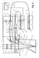
- an object 1 is to be viewed by means of a microscope, which has a schematically indicated microscope body 10 in a known per se construction.
- an optical system for generating an observation beam path 11 is mounted along an optical axis 12 in a manner known per se, which comprises a main objective 13, which is indicated only as a lens.
- an observation device in the widest sense
- an electromechanical movement device 17 such as an electromagnet, a rotor motor or a similar motor (disclosure: Paragraph 16, lines 33-34)
- filters 18 optionally one at the top of the observation beam path 11 (not shown) eyepiece. It is understood that in the case of a stereomicroscope, two such observation beam paths are provided.
- two light or illumination sources 20, 30 are provided, each having an illumination beam path 41 and 51 and a Umlenkspiegel Structure, preferably in the form of a mirror surface on a illumination prism 46 and 56, respectively each throw an illumination beam path 45 or 55 along an associated optical axis 44 or 54 onto the object 1 to be observed.
- the invention makes it possible to optimally adapt the illumination sources to the requirements. For example, for white light (ie for the light source 20) in particular a xenon lamp can be used. For light wavelengths in the range around 400 nm (blue light), a mercury vapor lamp is recommended, and for infrared, the most diverse light sources in question
- Each of these illumination beam paths from the light source 20 or 30 to the object 1 respectively comprises a lighting body 21 or 31, the light (here light is visible and invisible light, ie generally understood electromagnetic radiation) along an optical axis 22 and 32 respectively via an illumination optical system 23 or 33 to the inlet 24 or 34 of an optical waveguide 25 or 35 transmits, which directs the light to a light exit 26 and 36, respectively.
- the optical waveguide 25 or 35 is curved, that is shown as a fiber optic bundle, but the invention is by no means limited thereto, rather, the respective illumination source could be 20 or 30 quite well mounted so that its optical axis 22 and 32 with a on the microscope body 10 continuing optical axis 42 and 52 each of an illumination beam path 41 and 51 coincides.
- optical fibers are within the scope of Invention quite conceivable and possible, although the illustrated embodiment with optical fibers 25 and 35, or at least one of them, is preferred.
- a standard illumination source 20 is already built into the tripod of a surgical microscope.
- the optical fiber outlet 36 needs to be formed only as a connection for a subsequently to be coupled optical waveguide 35. Connections for optical waveguides are known per se, which is why a detailed discussion is omitted here. Expediently, this connection 34 is then attached to a separate illumination module 40, which can be attached to an existing microscope at most, with the corresponding optical parts 43 and 46.
- this converging lens 43 or 53 may be composed of a plurality of individual lenses.
- the two optical axes 42, 52 hit the mirror prisms 46 and 56 to be deflected in the already mentioned illumination beam path 45 and 55 with the optical axes 44 and 54, respectively.
- These illumination beam paths 45, 55 are now located near the observation beam path 11, for which reason a covering light aperture 16 is advantageously provided therebetween.
- one of the illumination sources 20 or 30 is now switched on, eg via a switch 62 connected to a control or monitoring device 60 (hand or foot switch, keypad or voice control, etc.) and via lines 63 and 64, respectively
- a switch 62 connected to a control or monitoring device 60 (hand or foot switch, keypad or voice control, etc.) and via lines 63 and 64, respectively
- object 1 for example with white light or with blue light.
- filters 38 and 58 for the excitation or 18 for the observation are brought into the respective beam path 11, 41 and 51, respectively.
- These are essentially similar electromechanical movement devices 37 and 57, respectively provided as already described above with reference to the device 17.
- All of these devices 17, 37 and 57 are controlled by the control device 60 and the switch 62 via the signal connection 61, 61 ', in such a way that the movement of the excitation filter 38, 58, but advantageously also of the observation filter 18, takes place synchronously.
- the controller may include as hardware or software a limit switch with feedback, which prevents the object is unintentionally illuminated simultaneously with white light and excitation light.
- Fig. 1 What in Fig. 1 is shown as a single filter 38 may (and this also applies to the other filters 18 and 58) comprise a plurality of successively arranged and optionally insertable filter.
- a filter for the white light mode is provided by which the spectrum of the light source 31 is corrected.
- an excitation filter is provided which only pivots in order to allow only the excitation wavelength to pass.
- the illumination energy of both light sources 21 and 31 can then be available with the desired excitation wavelength (with the filter 58 swiveled in), so that the intensity as a whole is increased.
- the switch 62 may also be used to turn off one of the light sources 20 or 30 when additional light is undesirable for an application.
- Filter exchangers with a plurality of filter sets can also be provided for a plurality of different - but also identical, synchronous - excitation and / or observation wavelengths, although the present invention also permits multiple connections (see the connection 36) for a plurality of light sources of different excitation spectral range provided.
- Fig. 2 differs from that of Fig. 1 essentially in that the excitation filter 58 ( Fig. 1 ) is omitted in the microscope body 10 and instead an excitation filter 28 installed in the light source 20 is, so that the electromechanical effort in the microscope body 10 is avoided or reduced. So this is preferred for structural reasons, especially since this embodiment has no detrimental effect on the function.
- the embodiment according to Fig. 3 differs from the previous embodiments by the placement of the filter.
- the output line 61 of the control unit 60 is connected to an electromechanical movement device or a central motor 67 in the microscope body 10, which adjusts a filter set 68 both in the observation beam path 11 and in the illumination beam path 45 or 55 such that at the same time the excitation filter 68a for the first and second light source 20 or 30 in the illumination beam paths 45 and 55 and the observation filter 68b in the observation beam path 11 become effective (or be removed from these beam paths).
- the cost of electromechanical movement devices is significantly reduced in this embodiment, although it must be taken into account that the device in the microscope body 10 must be accommodated. Which of the embodiments is therefore preferred, in particular which of those of Fig. 2 or Fig.
- Fig. 4 shows a combination of the versions Fig. 3 with that of Fig. 1 , It thus makes it possible, if necessary, to bring different illumination or excitation filters 68, 58 and / or 38 into effect, for which purpose the control unit 60 is equipped with corresponding control lines or signal buses 61, 61 '.
- This embodiment can of course be used for a wide variety of applications.
Abstract
Description
Die Erfindung bezieht sich auf ein Operations-Stereomikroskop mit Fluoreszenzbetriebsmodus mit einer Beleuchtungsquelle, deren Licht vorbestimmten spektralen Umfangs (Weisslicht) mittels einer Optikeinrichtung gegen ein zu betrachtendes Objekt richtbar ist. Wahlweise ist das Licht mindestens einer weiteren Beleuchtung in einem anderen Spektralbereich zuschaltbar.The invention relates to an operation stereomicroscope with fluorescence mode of operation with an illumination source whose light predetermined spectral range (white light) can be directed by means of an optical device against an object to be observed. Optionally, the light of at least one further illumination in a different spectral range is switchable.
Die Fluoreszenz ist eine hinreichend bekannte Methode, die mit Hilfe abgestimmter Filter ein definiertes Anregungsspektrum einem Objekt zuführt und die vom Objekt abgestrahlte Signalantwort spektral vom Anregungslicht trennt und der Beobachtung und Analyse zuführt. So sind etwa im klinischen Bereich viele Applikationen bekannt, die chirurgische Eingriffe unterstützen und über die ausgesendete Fluoreszenz das zu resizierende Gewebe markieren. Ein besonderes Beispiel für die Anwendung einer solchen Methode mit in ein Mikroskop integrierten Fluoreszenzeinrichtungen sind Operationsmikroskope für die Neurochirurgie, die unter Verwendung photodynamischer Medikamente, welche z.B. unter den Namen ALA (Amino Levulinic Acid = Amino-Lävulinsäure) oder mTHPC (meso-Tetra-HydroxyPhenyl-Chlorin) bekannt sind, eine totalere Operation bestimmter Tumore zulassen.Fluorescence is a well-known method which uses a matched filter to apply a defined excitation spectrum to an object and spectrally separate the signal response emitted by the object from the excitation light for observation and analysis. Thus, for example, in the clinical field many applications are known which support surgical interventions and mark the tissue to be resected via the emitted fluorescence. A particular example of the use of such a method with fluorescence devices integrated into a microscope are surgical microscopes for neurosurgery using photodynamic drugs containing e.g. known as ALA (Amino Levulinic Acid = Amino-Levulinic Acid) or mTHPC (Meso-Tetra-Hydroxy-Phenyl-Chlorin), may permit a more complete operation of certain tumors.
Eine andere Anwendung betrifft etwa die Infrarot-Angiographie, bei der mit Licht aus dem NIR-(nahen Infrarot-)Bereich zur Anregung verwendet wird, um dann das Objekt im langwelligeren Spektralbereich zu beobachten. Andere Anwendungen machen von (nicht sichtbarem) Ultraviolett Gebrauch. Andere Spektralbereiche zwischen Ultraviolett zu Blaulicht und von dort zu Rot- und bis zum fernen Infrarot sind ebenfalls möglich.Another application concerns, for example, infrared angiography, in which light from the NIR (near infrared) region is used for excitation, in order then to observe the object in the longer wavelength spectral range. Other applications use ultraviolet (not visible). Other spectral ranges between ultraviolet to blue light and from there to red and far infrared are also possible.
Dort, wo ein Gewebe bzw. ein Objekt, angeregt werden soll, ist die genügende Intensität des Anregungsspektrums von wesentlicher Bedeutung.Where a tissue or an object is to be excited, the sufficient intensity of the excitation spectrum is of essential importance.
Wenn etwa mit blauem Anregungslicht im Bereich von 380 - 420 nm gearbeitet wird, wird man je nach verwendetem Fluoreszenz-Wirkstoff ein bestimmtes Fluoreszenzsignal (z.B. bei ALA 635 nm) erhalten. Dazu werden im Allgemeinen Xenon-Lichtquellen von 300 W eingesetzt, die sowohl das normale mikroskopische Weisslicht, als auch das für die Fluoreszenz notwendige Blaulicht bereitstellen, nämlich Letzteres durch Filterung sowie Optimierung des Spektralbereichs von 380-420 nm durch gezielte Auswahl des Xenon-Brenners. Analoges gilt natürlich für andere Spektralbereiche. Beispiele für solche bekannten Mikroskope bzw. Operationsmikroskope finden sich etwa in der
Problematisch an diesen bekannten Mikroskopen ist, dass hier bei der Auswahl der Beleuchtungsquelle ein Kompromiss geschlossen werden muss, der letzten Endes dazu führt, dass die Weisslichtqualität für die Beobachtung nicht optimiert sein kann, anderseits gerade bei erhöhtem und optimierten Blaulichtanteil andere Spektralbereiche unterproportional vertreten sind und dann zu Farbstichen in der Standard-Weisslichtsituation führen. Zwar ist eine Korrektur des Farbstichs durch Filter theoretisch möglich, führt aber dann auch zur Reduktion der Intensität. Anderseits ist eine farblich richtige Beobachtung eines Operationsbereiches schon aus diagnostischen Gründen wichtig. Eine Steigerung der Intensität ist aber aufgrund der begrenzten Apertur der mikroskopischen Beleuchtungsoptik und anderer Effekte über eine Erhöhung der Lampenleistung nicht möglich.A problem with these known microscopes is that a compromise has to be made in the selection of the illumination source, which ultimately leads to the fact that the white light quality for the observation can not be optimized, on the other hand, other spectral regions are represented disproportionately even with increased and optimized blue light component and then lead to color casts in the standard white light situation. Although a correction of the color cast through filters is theoretically possible, but then leads to a reduction in intensity. On the other hand, a correct color observation of an operating area is important for diagnostic reasons. An increase in intensity is not possible due to the limited aperture of the microscopic illumination optics and other effects of an increase in lamp power.
Der vorliegenden Erfindung liegt deshalb die Aufgabe zugrunde, ein Mikroskop der eingangs genannten Art derart auszubilden, dass - trotz der gegebenen Einschränkung durch die Apertur der Beleuchtungsoptik - eine Intensitätserhöhung der Beleuchtung sowohl im Weisslichtbetrieb, wie auch im Anregungsmodus möglich ist. Eine weitere Aufgabe der Erfindung liegt darin, die Weisslichtqualität zu verbessern.The present invention is therefore based on the object, a microscope of the type mentioned in such a way that - despite the given restriction by the aperture of the illumination optics - an increase in intensity of the illumination in both white light operation, as well as in the excitation mode is possible. Another object of the invention is to improve the quality of white light.
Zur Lösung dieser Aufgaben wird erfindungsgemäss vorgeschlagen, dass die Optikeinrichtung mit mindestens einem Anschluss für eine weitere Beleuchtungsquelle versehen ist. Erfindungsgemäss soll also mindestens ein Anschluss für eine weitere Beleuchtungsquelle vorgesehen sein, wobei es dann ohne Weiteres möglich ist, die eine Beleuchtungsquelle mit dem vorbestimmten Spektralbereich als Weisslichtquelle zu optimieren, die andere hingegen mit demjenigen Spektralbereich optimiert einzusetzen, welcher für eine bestimmte Anwendung gerade erforderlich und zweckmässig ist. Denkbar wäre sogar die Anordnung mehrerer Anschlüsse für mehr als zwei Beleuchtungsquellen, die dann durch entsprechende optische und/oder elektrische Schalteinrichtungen zur Wirkung gebracht werden können.To solve these problems, the invention proposes that the Optics device is provided with at least one connection for a further illumination source. Thus, according to the invention, at least one connection should be provided for a further illumination source, whereby it is then readily possible to optimize one illumination source with the predetermined spectral range as a white light source, while the other uses that spectral range which is just required for a particular application is appropriate. It would even be conceivable to arrange a plurality of connections for more than two illumination sources, which can then be brought into effect by appropriate optical and / or electrical switching devices.
Es ist im Rahmen der Erfindung aber auch möglich, die jeweilige weitere Beleuchtungsquelle in das Mikroskop zu integrieren, wobei die Ausbildung so getroffen werden kann, dass das Mikroskop dann die mindestens eine weitere Beleuchtungseinrichtung enthält, und dass diese weitere Beleuchtungseinrichtung einen vom vorbestimmten spektralen Umfang abweichenden spektralen Umfang besitzt.However, it is also possible within the scope of the invention to integrate the respective further illumination source into the microscope, wherein the embodiment can be made such that the microscope then contains the at least one further illumination device, and that this further illumination device deviates from the predetermined spectral range has spectral scope.
Weitere Ausgestaltungen der Erfindung ergeben sich aus der nachfolgenden symbolischen und beispielhaften Beschreibung an Hand der Figuren sowie aus den abhängigen Ansprüchen, wobei die Bezugszeichenliste Bestandteil der Offenbarung ist. In der Beschreibung werden die Figuren zusammenhängend und übergreifend beschrieben. Gleiche Bezugszeichen bedeuten gleiche Bauteile, Bezugszeichen einer unterschiedlichen Dekade (10, 20, 30, etc.) geben funktionsgleiche oder ähnliche Bauteile an. Es zeigen dabei die
Gemäss
Um das Objekt 1 auch entsprechend zu beleuchten, sind erfindungsgemäss (mindestens) zwei Licht- bzw. Beleuchtungsquellen 20, 30 vorgesehen, die über je einen Beleuchtungsstrahlengang 41 bzw. 51 und eine Umlenkspiegelfläche, vorzugsweise in Form einer Spiegelfläche an einem Beleuchtungsprisma 46 bzw. 56 je einen Beleuchtungsstrahlengang 45 bzw. 55 entlang einer zugehörigen optischen Achse 44 bzw. 54 auf das zu beobachtende Objekt 1 werfen. Durch die Erfindung ist es möglich, die Beleuchtungsquellen optimal den Erfordernissen anzupassen. Beispielsweise kann für Weisslicht (also für die Lichtquelle 20) besonders eine Xenonlampe eingesetzt werden. Für Lichtwellenlängen im Bereiche um 400 nm (Blaulicht) wird sich eine Quecksilberdampflampe empfehlen, und für Infrarot kommen die verschiedensten Lichtquellen in FrageIn order to illuminate the object 1 also according to the invention (at least) two light or
Jeder dieser Beleuchtungsstrahlengänge von der Lichtquelle 20 bzw. 30 zum Objekt 1 umfasst jeweils einen Beleuchtungskörper 21 bzw. 31, der Licht (hier sei unter "Licht" sichtbares und unsichtbares Licht, also allgemein elektromagnetische Strahlung verstanden) entlang einer optischen Achse 22 bzw. 32 über eine Beleuchtungsoptik 23 bzw. 33 zum Eintritt 24 bzw. 34 eines Lichtwellenleiters 25 bzw. 35 sendet, der das Licht zu einem Lichtaustritt 26 bzw. 36 leitet. In der Zeichnung ist der Lichtwellenleiter 25 bzw. 35 gekrümmt, d.h. als Lichtleitfaserbündel dargestellt, doch ist die Erfindung keineswegs darauf beschränkt, vielmehr könnte die jeweilige Beleuchtungsquelle 20 bzw. 30 durchaus auch so angebracht sein, dass ihre optische Achse 22 bzw. 32 mit einer am Mikroskopkörper 10 weiterführenden optischen Achse 42 bzw. 52 je eines Beleuchtungsstrahlengangs 41 bzw. 51 zusammenfällt. Auch andere Arten von Lichtwellenleitern sind im Rahmen der Erfindung durchaus denkbar und möglich, wenngleich die dargestellte Ausführung mit Lichtwellenleitern 25 bzw. 35, oder wenigstens einem davon, bevorzugt ist. Für gewöhnlich ist etwa eine Standard-Beleuchtungsquelle 20 bereits in das Stativ eines Operationsmikroskops eingebaut. Für die erfindungsgemäss vorgesehene zweite Lichtquelle 30, die allenfalls als externes Gerät vorliegen kann, braucht an sich der Lichtleiteraustritt 36 nur als Anschluss für einen nachträglich anzukuppelnden Lichtwellenleiter 35 ausgebildet sein. Anschlüsse für Lichtwellenleiter sind an sich bekannt, weshalb hier auf eine detaillierte Erörterung verzichtet wird. Zweckmässig ist dieser Anschluss 34 dann an einem eigenen, allenfalls an ein bestehendes Mikroskop anbaubaren Beleuchtungsmodul 40 mit den entsprechenden Optikteilen 43 und 46 angebracht.Each of these illumination beam paths from the
Wie bereits angedeutet, führt die Austrittsseite 26 bzw. 36 des jeweiligen Lichtwellenleiters 25 bzw. 35 direkt zu einem optischen System entlang der optischen Achsen 42 und 52 von Beleuchtungsstrahlengängen 41 bzw. 51, an welchen Achsen je eine Beleuchtungssammellinse 43 bzw. 53 angeordnet ist. Natürlich kann diese Sammellinse 43 bzw. 53 aus mehreren Einzellinsen zusammengesetzt sein.As already indicated, the exit side leads 26 and 36 of the respective
Schliesslich treffen die beiden optischen Achsen 42, 52 auf die Spiegelprismen 46 und 56, um in den schon erwähnten Beleuchtungsstrahlengang 45 bzw. 55 mit den optischen Achsen 44 und 54 umgelenkt zu werden. Diese Beleuchtungsstrahlengänge 45, 55 befinden sich nun nahe des Beobachtungsstrahlengangs 11, weshalb vorteilhaft dazwischen eine abdeckende Lichtblende 16 vorgesehen ist.Finally, the two
Im Betrieb wird nun, z.B. über einen mit einem Steuer- oder Kontrollgerät 60 verbundenen Schalter 62 (Hand- oder Fussschalter, Tastenfeld oder Sprachkontrolle, etc.) und über Leitungen 63 bzw. 64 jeweils eine der Beleuchtungsquellen 20 bzw. 30 eingeschaltet, um das Objekt 1 beispielsweise mit Weisslicht oder mit Blaulicht anzustrahlen. Soll auf eine Anregungswellenlänge bzw. -spektrum umgeschaltet werden, dann werden Filter 38 bzw. 58 für die Anregung bzw. 18 für die Beobachtung in den jeweiligen Strahlengang 11, 41 bzw. 51 gebracht. Dazu sind im Wesentlichen ähnliche elektromechanische Bewegungseinrichtungen 37 bzw. 57 vorgesehen wie oben anhand der Einrichtung 17 bereits beschrieben wurde. Alle diese Einrichtungen 17, 37 und 57 werden von der Kontrolleinrichtung 60 bzw. dem Schalter 62 über die Signalverbindung 61, 61' gesteuert, und zwar so, dass die Bewegung der Anregungsfilter 38, 58, vorteilhaft aber auch des Beobachtungsfilters 18, synchron erfolgt. Das bedeutet, dass diese Filter im Anregungsmodus gemeinsam in den jeweiligen Strahlengang bewegt und im Weisslichtmodus auch synchron aus dem Strahlengang bewegt werden. Dabei kann das Steuergerät als Hardware oder Software einen Endschalter mit Rückmeldung beinhalten, der verhindert, dass das Objekt ungewollt gleichzeitig mit Weisslicht und Anregungslicht beleuchtet wird.In operation, one of the
Was in
Das Ausführungsbeispiel der
Auch die Ausführungsform nach
Die Ausführungsform nach
Im Rahmen der Erfindung sind zahlreiche Varianten möglich. Erfindungsgemäss ist vorgesehen, wenn für jedes der jeweils vorhandenen Filter 18, 28, 38, 58, 68 eine eigene elektromechanische Bewegungseinrichtung (also im weitesten Sinne ein "Motor" in seiner Bedeutung als "Beweger") vorgesehen ist.In the context of the invention numerous variants are possible. According to the invention, it is provided that, for each of the
Entscheidend sind erfindungsgemäss die Variationsmöglichkeiten, die sich aus der Kombination zweier regulierbaren Beleuchtungseinrichtungen ergeben. Demzufolge liegt auch eine Ausgestaltungsvariante eines Stereomikroskops im Rahmen der Erfindung, die eine herkömmliche Mikroskopbeleuchtung plus dem regulierbaren Paar der erfindungsgemässen Beleuchtungsvorrichtungen umfasst.
Nachfolgend der Text der ursprünglichen Ansprüche aus der Stammanmeldung, die im Rahmen dieser Teilanmeldung ausschliesslich aus Gründen der Übernahme ihres Offenbarungsinhaltes hier wieder gegeben werden und in der vorliegenden Form nicht beansprucht werden.
- A. Stereomikroskop mit einer Beleuchtungsquelle (20), deren Licht im Betriebszustand in einem regulierbaren spektralen Bereich liegt und gegen ein zu betrachtendes Objekt (1) richtbar ist, dadurch gekennzeichnet, dass es mindestens eine weitere Beleuchtungseinrichtung (30) enthält, deren Licht im Betriebszustand ebenfalls regulierbar im gleichen spektralen Bereich liegt.
- B. Stereomikroskop nach A, dadurch gekennzeichnet, dass der Spektralbereich der mindestens einen weiteren Beleuchtungseinrichtung (30) in einem von der ersten Beleuchtungseinrichtung (20) abweichenden Spektralbereich liegt.
- C. Stereomikroskop nach B, dadurch gekennzeichnet, dass der von der ersten Beleuchtungseinrichtung (20) abweichende spektrale Bereich der mindestens einen weiteren Beleuchtungseinrichtung (30) im Blaulichtbereich von 380-420 nm liegt.
- D. Stereomikroskop nach B, dadurch gekennzeichnet, dass der abweichende spektrale Bereich der mindestens einen weiteren Beleuchtungseinrichtung (30) im Ultraviolettbereich liegt.
- E. Stereomikroskop nach B, dadurch gekennzeichnet, dass der abweichende spektrale Bereich der mindestens einen weiteren Beleuchtungseinrichtung (30) im Infrarotbereich liegt.
- F. Stereomikroskop nach einem der vorhergehenden Punkte, dadurch gekennzeichnet, dass in mindestens eine der Beleuchtungsquellen (20 bzw. 30) wenigstens ein Beleuchtungs- und/oder Anregungsfilter (28 bzw. 38) in den Strahlengang des Beleuchtungskörpers (21 bzw. 31) bewegbar ist.
- G. Stereomikroskop nach F, dadurch gekennzeichnet, dass das wenigstens eine Beleuchtungs- und/oder Anregungsfilter (28 bzw. 38) in zumindest einer der Beleuchtungsquellen (20 bzw. 30) mit Hilfe einer elektromechanischen Bewegungseinrichtung (27 bzw. 37) bewegbar ist.
- H. Stereomikroskop nach Anspruch G, dadurch gekennzeichnet, dass die elektromechanische Bewegungseinrichtung (27 bzw. 37) in zumindest einer der Beleuchtungsquellen (20 bzw. 30) von einer zentralen Kontrolleinrichtung (60) gesteuert ist, die vorzugsweise zur Vermeidung von Fehlfunktionen mit einem Endschalter mit Rückmeldung versehen ist.
- I. Stereomikroskop nach einem der vorhergehenden Punkte, dadurch gekennzeichnet, dass ein gemeinsamer Filtersatz (68) vorgesehen ist, der sowohl in den Beobachtungsstrahlengang (11) als auch in den Beleuchtungsstrahlengang bzw. die Beleuchtungsstrahlengänge (45 bzw. 55) bewegbar ist.
- J. Stereomikroskop nach G, dadurch gekennzeichnet, dass eine gemeinsame elektromechanische Bewegungseinrichtung (67) zugeordnet ist.
- K. Stereomikroskop nach einem der vorhergehenden Punkte, dadurch gekennzeichnet, dass Beleuchtungs- und/oder Anregungsfilter (28, 38, 58) für die Strahlengänge (22, 32, 41, 51, 45, 55) der zumindest zwei Beleuchtungsquellen (20, 30) vorgesehen sind, und dass eine gemeinsame Kontrolleinrichtung (60) zum synchronen Bewegen der Beleuchtungs-und/oder Anregungsfilter (28, 38, 58) vorgesehen ist.
- L. Stereomikroskop nach K, dadurch gekennzeichnet, dass in den Beobachtungsstrahlengang (11) ein Beobachtungsfilter (18) mit Hilfe einer elektromechanischen Bewegungseinrichtung (17) bewegbar ist, und dass diese elektromechanische Bewegungseinrichtung (17) ebenfalls von der gemeinsamen Kontrolleinrichtung (60) gesteuert ist.
- M. Stereomikroskop nach einem der vorhergehenden Punkte, dadurch gekennzeichnet, dass ein Weisslicht-Korrekturfilter in den Strahlengang der ersten Beleuchtungsquelle (20) bewegbar ist.
- N. Stereomikroskop nach einem der vorhergehenden Punkte, dadurch gekennzeichnet, dass es als Operationsmikroskop ausgebildet ist.
Below is the text of the original claims from the parent application, which are given here in the context of this divisional application exclusively for the sake of taking over their disclosure content here and are not claimed in the present form.
- A. Stereomicroscope with an illumination source (20), the light is in the operating state in an adjustable spectral range and directed towards an object to be observed (1), characterized in that it contains at least one further illumination device (30), the light in the operating state is also adjustable in the same spectral range.
- B. stereomicroscope according to A, characterized in that the spectral range of the at least one further illumination device (30) in one of the first illumination device (20) deviating spectral range.
- C. Stereomicroscope according to B, characterized in that the spectral range of the at least one further illumination device (30) deviating from the first illumination device (20) lies in the blue-light range of 380-420 nm.
- D. Stereomicroscope according to B, characterized in that the deviating spectral range of the at least one further illumination device (30) is in the ultraviolet range.
- E. Stereomicroscope according to B, characterized in that the deviating spectral range of the at least one further illumination device (30) is in the infrared range.
- Stereomicroscope according to one of the preceding points, characterized in that in at least one of the illumination sources (20 or 30) at least one illumination and / or excitation filter (28 or 38) in the beam path of the lighting fixture (21 or 31) movable is.
- G. Stereomicroscope according to F, characterized in that the at least one illumination and / or excitation filter (28 or 38) in at least one of the illumination sources (20 or 30) by means of an electromechanical movement means (27 or 37) is movable.
- H. Stereomicroscope according to claim G, characterized in that the electromechanical movement device (27 or 37) in at least one of the illumination sources (20 or 30) by a central control device (60) is controlled, preferably to avoid malfunction with a limit switch is provided with feedback.
- I. Stereomicroscope according to one of the preceding points, characterized in that a common filter set (68) is provided which is movable both in the observation beam path (11) and in the illumination beam path or the illumination beam paths (45 and 55).
- J. stereomicroscope according to G, characterized in that a common electromechanical movement device (67) is associated.
- K. Stereomicroscope according to one of the preceding points, characterized in that illumination and / or excitation filter (28, 38, 58) for the beam paths (22, 32, 41, 51, 45, 55) of the at least two illumination sources (20, 30 ) are provided, and that a common control device (60) for synchronous movement of the illumination and / or excitation filter (28, 38, 58) is provided.
- L. Stereomicroscope according to K, characterized in that in the observation beam (11) an observation filter (18) by means of an electromechanical movement means (17) is movable, and that said electromechanical movement means (17) is also controlled by the common control device (60) ,
- M. stereomicroscope according to one of the preceding points, characterized in that a white light correction filter in the beam path of the first illumination source (20) is movable.
- N. Stereomicroscope according to one of the preceding points, characterized in that it is designed as a surgical microscope.
- 1- :1- :
- Objektobject
- 10 - :10 -:
- Mikroskopkörpermicroscope body
- 11 - :11 -:
- BeobachtungsstrahlengangObservation beam path
- 12 - :12 -:
- Optische Achse von 11Optical axis of 11
- 13- :13-:
- Hauptobjektivmain objective
- 14 - :14 -:
- Linse oder LinsengruppeLens or lens group
- 15- :15-:
- Linse oder LinsengruppeLens or lens group
- 16- :16-:
- LichtblendeLens hood
- 17- :17-:
- Elektromechanische BewegungseinrichtungElectromechanical movement device
- 18- :18-:
- Filterfilter
- 20- :20-:
- Lichtquelle 1, BeleuchtungseinrichtungLight source 1, lighting device
- 21 - :21 -:
- Beleuchtungskörperlighting
- 22 - :22 -:
- Optische Achse der LichtquelleOptical axis of the light source
- 23- :23-:
- Beleuchtungsoptikillumination optics
- 24- :24-:
- Lichtwellenleiter-EintrittOptical fiber entry
- 25 - :25 -:
- Lichtwellenleiteroptical fiber
- 26- :26-:
- Lichtwellenleiter-AustrittOptical fiber outlet
- 27 - :27 -:
- Elektromechanische BewegungseinrichtungElectromechanical movement device
- 28 - :28 -:
- Beleuchtung-/AnregungsfilterLighting / excitation filter
- 30- :30-:
-
Lichtquelle 2
Light source 2 - 31- :31-:
- Beleuchtungskörperlighting
- 32- :32-:
- Optische Achse der LichtquelleOptical axis of the light source
- 33- :33-:
- Beleuchtungsoptikillumination optics
- 34 - :34 -:
- Lichtwellenleiter EintrittFiber optic cable entry
- 35 - :35 -:
- Lichtwellenleiteroptical fiber
- 36 - :36 -:
- Lichtwellenleiter Austritt, AnschlussFiber optic outlet, connection
- 37 - :37 -:
- Elektromechanische BewegungseinrichtungElectromechanical movement device
- 38 - :38 -:
- Beleuchtung-/AnregungsfilterLighting / excitation filter
- 40 - :40 -:
- Beleuchtungsmodullighting module
- 41 - :41 -:
- BeleuchtungsstrahlenbündelIllumination beam
- 42- :42-:
- Optische Achse des BeleuchtungsstrahlengangsOptical axis of the illumination beam path
- 43- :43-:
- BeleuchtungssammellinseLighting collective lens
- 44- :44-:
- Optische Achse des BeleuchtungsfeldbündelsOptical axis of the illumination field bundle
- 45 - :45 -:
- BeleuchtungsstrahlengangIllumination beam path
- 46- :46-:
- Beleuchtungsprismalighting prism
- 51- :51-:
- BeleuchtungsstrahlengangIllumination beam path
- 52- :52-:
- Optische Achse des BeleuchtungsstrahlengangsOptical axis of the illumination beam path
- 53 - :53 -:
- BeleuchtungssammellinseLighting collective lens
- 54- :54-:
-
Optische Achse des Beleuchtungsstrahlengangs 55Optical axis of the
illumination beam path 55 - 55 - :55 -:
- BeleuchtungsstrahlengangIllumination beam path
- 56 - :56 -:
- Beleuchtungsprismalighting prism
- 57- :57-:
- Elektromechanische BewegungseinrichtungElectromechanical movement device
- 58- :58-:
- Beleuchtungs-/AnregungsfilterIllumination / excitation filter
- 60- :60-:
- Steuergerät/KontrolleinrichtungControl unit / control device
- 61- :61-:
- Steuersignal/SignalbusControl signal / signal bus
- 62- :62-:
- Schalterswitch
- 63- :63-:
- Steuersignal/SignalbusControl signal / signal bus
- 64- :64-:
- Steuersignal/SignalbusControl signal / signal bus
- 67- :67-:
- Elektromechanische BewegungseinrichtungElectromechanical movement device
- 68, a, b - :68, a, b -:
- Beleuchtungs- und BeobachtungsfilterLighting and observation filter
Claims (7)
deren Licht im Betriebszustand in einem regulierbaren spektralen Bereich liegt und über einen einbringbaren Anregungsfilter für Fluoreszenzanregung verfügt und entlang voneinander unabhängigen Beleuchtungsstrahlengängen (42, 52, 44,54) gegen ein zu betrachtendes Objekt (1) richtbar ist,
dadurch gekennzeichnet, dass es mindestens eine weitere
zuschaltbare
Beleuchtungseinrichtung (30) enthält, deren Licht im Betriebszustand ebenfalls regulierbar in einem vom Weisslicht abweichenden
Spektralbereich liegt, und dass in mindestens eine der Beleuchtungsquellen (20 bzw. 30) wenigstens ein Anregungsfilter (28 bzw. 38) in den Strahlengang des Beleuchtungskörpers (21 bzw. 31) bewegbar ist, und
dass die Anregungsfilter (28, 38,58) in zumindest einer der Beleuchtungsquellen (20 bzw. 30) mit Hilfe einer elektromechanischen Bewegungseinrichtung (27 bzw. 37) bewegbar sind, und
dass die elektromechanische Bewegungseinrichtung (27 bzw. 37) in beiden Beleuchtungsquellen (20 bzw. 30) von einer zentralen Kontrolleinrichtung (60) gesteuert ist, die vorzugsweise zur Vermeidung von Fehlfunktionen mit einem Endschalter mit Rückmeldung versehen ist, und
dass die gemeinsame Kontrolleinrichtung (60) zum synchronen Bewegen der Anregungsfilter (28,38,58) vorgesehen ist, und
dass in den Beobachtungsstrahlengang (11) ein Beobachtungsfilter (18) mit Hilfe einer elektromechanischen Bewegungseinrichtung (17,67) bewegbar ist, und
dass diese elektromechanische Bewegungseinrichtung (17,67) ebenfalls von der gemeinsamen Kontrolleinrichtung (60) gesteuert ist, und
dass die beiden Beleuchtungsquellen (20,30) im Anregungsmodus ihr AnregungsLicht gleichzeitig (parallel) über je einen Beleuchtungsstrahlengang 41 bzw. 51 und eine Umlenkspiegelfläche, vorzugsweise in Form einer Spiegelfläche an einem Beleuchtungsprisma 46 bzw. 56 je einen Beleuchtungsstrahlengang 45 bzw. 55 entlang einer zugehörigen optischen Achse 44 bzw. 54 auf das zu beobachtende Objekt 1 werfen, und
dass die Anregungsfilter (28,38,58,68) im Weisslichtmodus synchron aus den Strahlengängen bewegt sind.Fluorescence operation stereomicroscope with a white light illumination source (20),
whose light is in the operating state in a regulatable spectral range and has an insertable excitation filter for fluorescence excitation and along independent illumination beam paths (42, 52, 44, 54) can be directed against an object to be observed (1),
characterized in that it is at least one more
switchable
Lighting device (30) contains, the light in the operating state also adjustable in a deviating from the white light
Spectral range, and that in at least one of the illumination sources (20 and 30) at least one excitation filter (28 or 38) in the beam path of the illumination body (21 or 31) is movable, and
in that the excitation filters (28, 38, 58) can be moved in at least one of the illumination sources (20 or 30) by means of an electromechanical movement device (27 or 37), and
in that the electromechanical movement device (27 or 37) in both illumination sources (20 or 30) is controlled by a central control device (60), which is preferably provided with a limit switch for avoiding malfunctions, and
in that the common control device (60) is provided for synchronously moving the excitation filters (28, 38, 58), and
that in the observation beam path (11), an observation filter (18) by means of an electromechanical movement means (17,67) is movable, and
that this electromechanical movement device (17, 67) is also controlled by the common control device (60), and
that the two illumination sources (20,30) in the excitation mode their excitation light simultaneously (parallel) via a respective illumination beam path 41 and 51 and a Umlenkspiegelfläche, preferably in the form of a mirror surface on a illumination prism 46 and 56 each have an illumination beam path 45 and 55, respectively along an associated optical axis 44 and 54, respectively, to the object 1 to be observed, and
that the excitation filter (28,38,58,68) are moved in the white light mode in synchronism from the beam paths.
zu den einzelnen Anregungsfiltern (28,38,58) und Beobachtungsfilter (18) ein gemeinsamer Filtersatz (68, 68a)
vorgesehen ist, der sowohl in den Beobachtungsstrahlengang (11) als auch in den Beleuchtungsstrahlengang bzw. die Beleuchtungsstrahlengänge (45 bzw. 55) bewegbar ist.Stereomicroscope according to one of the preceding claims, characterized in that alternatively or additionally
a common filter set (68, 68a) for the individual excitation filters (28, 38, 58) and observation filters (18)
is provided, which is movable in both the observation beam path (11) and in the illumination beam path or the illumination beam paths (45 and 55).
eine gemeinsame elektromechanische Bewegungseinrichtung (67) zugeordnet ist.Stereomicroscope according to claim 5, characterized in that the common filter set (68,68a)
a common electromechanical movement device (67) is assigned.
Applications Claiming Priority (2)
| Application Number | Priority Date | Filing Date | Title |
|---|---|---|---|
| DE102005005984.8A DE102005005984B4 (en) | 2005-02-09 | 2005-02-09 | Fluorescence / infrared device for surgical microscopes |
| EP06100806A EP1691229A1 (en) | 2005-02-09 | 2006-01-25 | Surgical Microscope comprising two illumination Units |
Related Parent Applications (1)
| Application Number | Title | Priority Date | Filing Date |
|---|---|---|---|
| EP06100806.6 Division | 2006-01-25 |
Publications (2)
| Publication Number | Publication Date |
|---|---|
| EP2278376A2 true EP2278376A2 (en) | 2011-01-26 |
| EP2278376A3 EP2278376A3 (en) | 2013-06-26 |
Family
ID=35999440
Family Applications (2)
| Application Number | Title | Priority Date | Filing Date |
|---|---|---|---|
| EP10186203.5A Withdrawn EP2278376A3 (en) | 2005-02-09 | 2006-01-25 | Surgical microscope comprising two illumination units |
| EP06100806A Ceased EP1691229A1 (en) | 2005-02-09 | 2006-01-25 | Surgical Microscope comprising two illumination Units |
Family Applications After (1)
| Application Number | Title | Priority Date | Filing Date |
|---|---|---|---|
| EP06100806A Ceased EP1691229A1 (en) | 2005-02-09 | 2006-01-25 | Surgical Microscope comprising two illumination Units |
Country Status (4)
| Country | Link |
|---|---|
| US (1) | US7649685B2 (en) |
| EP (2) | EP2278376A3 (en) |
| JP (1) | JP5022606B2 (en) |
| DE (1) | DE102005005984B4 (en) |
Families Citing this family (12)
| Publication number | Priority date | Publication date | Assignee | Title |
|---|---|---|---|---|
| DE102009024942A1 (en) * | 2009-06-09 | 2010-12-23 | Carl Zeiss Surgical Gmbh | Light source arrangement for a lighting device of a medical-optical observation device |
| DE102010044502A1 (en) | 2010-09-06 | 2012-03-08 | Leica Microsystems (Schweiz) Ag | Special lighting Video Operations stereomicroscope |
| DE102010044503B4 (en) * | 2010-09-06 | 2017-11-02 | Leica Microsystems (Schweiz) Ag | Operations fluorescence stereomicroscope |
| EP2821004B1 (en) * | 2011-04-18 | 2015-08-05 | Karl Storz GmbH & Co. KG | Exoscope |
| US8810905B2 (en) * | 2012-01-30 | 2014-08-19 | Kenneth W. Bauer | Stereomicroscope fluorescence system |
| DE102012201371A1 (en) | 2012-01-31 | 2013-08-01 | Leica Microsystems (Schweiz) Ag | Multiphoton fluoroscopy attachment module for a surgical microscope |
| DE102012001854A1 (en) * | 2012-02-01 | 2013-08-01 | Leica Microsystems (Schweiz) Ag | Special lighting Operations stereomicroscope |
| CN104662388B (en) * | 2012-05-07 | 2018-06-26 | 卡尔蔡司工业测量技术有限公司 | For the replaceable lighting module of coordinate measuring machine |
| DE102013226784A1 (en) * | 2013-12-19 | 2015-06-25 | Leica Microsysteme (Schweiz) AG | surgical microscope |
| DE102015003681B4 (en) | 2015-03-24 | 2023-12-21 | Karl Storz Se & Co. Kg | Device for recording an image of an object field on a human or animal body |
| DE102019101773B9 (en) * | 2019-01-24 | 2021-11-25 | Carl Zeiss Meditec Ag | Microscopy system and method for operating a microscopy system |
| DE102022206219A1 (en) | 2022-06-22 | 2023-12-28 | Robert Bosch Gesellschaft mit beschränkter Haftung | Optical system with filter carrier |
Citations (2)
| Publication number | Priority date | Publication date | Assignee | Title |
|---|---|---|---|---|
| DE19548913A1 (en) | 1995-12-31 | 1997-07-03 | Storz Karl Gmbh & Co | Diagnostic device for photosensitised reaction in living tissue |
| US6510338B1 (en) | 1998-02-07 | 2003-01-21 | Karl Storz Gmbh & Co. Kg | Method of and devices for fluorescence diagnosis of tissue, particularly by endoscopy |
Family Cites Families (20)
| Publication number | Priority date | Publication date | Assignee | Title |
|---|---|---|---|---|
| US3798435A (en) * | 1973-08-09 | 1974-03-19 | Reichert Optische Werke Ag | Versatile light source for a microscope |
| JP3015082B2 (en) * | 1990-08-28 | 2000-02-28 | オリンパス光学工業株式会社 | Microscope capable of simultaneous observation of transmission and epi-illumination and automatic light control method thereof |
| US5491343A (en) * | 1994-03-25 | 1996-02-13 | Brooker; Gary | High-speed multiple wavelength illumination source, apparatus containing the same, and applications thereof to methods of irradiating luminescent samples and of quantitative luminescence ratio microscopy |
| JP3172060B2 (en) * | 1995-06-23 | 2001-06-04 | 沖電気工業株式会社 | Simultaneous measurement method for intracellular ion concentration change and membrane potential change |
| DE29620732U1 (en) * | 1995-09-26 | 1997-04-24 | Storz Karl Gmbh & Co | Device for photodynamic diagnosis |
| DE19825947A1 (en) | 1998-06-11 | 1999-12-16 | Volker Heerich | Forensic microscope especially for handwriting analysis |
| JP2000235002A (en) * | 1999-02-15 | 2000-08-29 | Fuji Photo Film Co Ltd | Photographic method and photographic device |
| JP2002182117A (en) * | 2000-12-14 | 2002-06-26 | Nikon Corp | Optical microscope |
| WO2002074339A1 (en) * | 2001-03-16 | 2002-09-26 | University Of Utah Research Foundation | Deveice and method for the photodynamic diagnosis of tumor tissue |
| DE10123785A1 (en) | 2001-05-16 | 2002-11-21 | Leica Microsystems | Device for illuminating a field of view, for example an object field under a microscope by two light sources |
| US6754414B2 (en) * | 2001-09-27 | 2004-06-22 | Bio-Rad Laboratories, Inc. | Imaging of microarrays using fiber optic exciter |
| JP2003126017A (en) * | 2001-10-25 | 2003-05-07 | Olympus Optical Co Ltd | Surgical microscope system |
| US6819484B2 (en) * | 2001-11-06 | 2004-11-16 | Olympus Optical Co., Ltd. | Total internal reflection illumination apparatus and microscope using this total internal reflection illumination apparatus |
| JP2004029205A (en) * | 2002-06-24 | 2004-01-29 | Olympus Corp | Laser scanning microscope |
| DE20321352U1 (en) * | 2002-08-28 | 2006-12-21 | Carl Zeiss Surgical Gmbh | Microscopy system for visualizing fluorescence of indocyanine green in object to be inspected, has microscopy optics with first beam path and second beam path, display system, and illumination system |
| DE10252313B9 (en) * | 2002-11-11 | 2006-10-19 | Carl Zeiss | Investigation system for the simultaneous direct visualization of a fluorescent label and a tissue region surrounding the fluorescent label and method of investigation therefor |
| DE10303825A1 (en) * | 2003-01-31 | 2004-08-12 | Leica Microsystems (Schweiz) Ag | Microscope with illumination |
| DE10314125B4 (en) * | 2003-03-28 | 2005-02-24 | Carl Zeiss Jena Gmbh | Arrangement for illuminating objects with light of different wavelengths |
| US7050224B2 (en) * | 2003-11-07 | 2006-05-23 | Olympus Corporation | Fluorescence observing apparatus |
| JP4546741B2 (en) * | 2004-01-08 | 2010-09-15 | オリンパス株式会社 | Fluorescence microscope |
-
2005
- 2005-02-09 DE DE102005005984.8A patent/DE102005005984B4/en active Active
-
2006
- 2006-01-25 EP EP10186203.5A patent/EP2278376A3/en not_active Withdrawn
- 2006-01-25 EP EP06100806A patent/EP1691229A1/en not_active Ceased
- 2006-02-06 JP JP2006028633A patent/JP5022606B2/en active Active
- 2006-02-08 US US11/349,777 patent/US7649685B2/en active Active
Patent Citations (2)
| Publication number | Priority date | Publication date | Assignee | Title |
|---|---|---|---|---|
| DE19548913A1 (en) | 1995-12-31 | 1997-07-03 | Storz Karl Gmbh & Co | Diagnostic device for photosensitised reaction in living tissue |
| US6510338B1 (en) | 1998-02-07 | 2003-01-21 | Karl Storz Gmbh & Co. Kg | Method of and devices for fluorescence diagnosis of tissue, particularly by endoscopy |
Also Published As
| Publication number | Publication date |
|---|---|
| EP2278376A3 (en) | 2013-06-26 |
| JP2006221167A (en) | 2006-08-24 |
| DE102005005984A1 (en) | 2006-08-24 |
| EP1691229A1 (en) | 2006-08-16 |
| DE102005005984B4 (en) | 2019-10-24 |
| US7649685B2 (en) | 2010-01-19 |
| JP5022606B2 (en) | 2012-09-12 |
| US20060198001A1 (en) | 2006-09-07 |
Similar Documents
| Publication | Publication Date | Title |
|---|---|---|
| EP2278376A2 (en) | Surgical microscope comprising two illumination units | |
| DE102010044503B4 (en) | Operations fluorescence stereomicroscope | |
| DE20122782U1 (en) | lighting device | |
| DE102010039950B4 (en) | Microscope with micro and macro objectives | |
| DE102009025127A1 (en) | Lighting device for an optical observation device | |
| DE102006048054A1 (en) | Multispectral illumination device | |
| DE102004050651A1 (en) | Lighting device and observation device | |
| WO2005122876A1 (en) | Variable diaphragm, illumination device, optical observation device and optical observation appliance | |
| EP2045641A2 (en) | Illumination device | |
| DE102014016850A1 (en) | Optical system for fluorescence observation | |
| EP1441249A1 (en) | Surgical microscope | |
| DE102009017710B4 (en) | An optical observation device and method for ensuring a constant illumination intensity when the color temperature of the illumination changes | |
| EP1291696B1 (en) | Prism configuration for simultaneous 0 and oblique angle illumination in a stereo surgical microscope | |
| EP3792676B1 (en) | Endoscope with optical filter arrangement and use | |
| DE102013206466B4 (en) | fluorescence microscope | |
| EP3747348A1 (en) | Light source and system for and method of fluorescence diagnosis | |
| WO2017036893A1 (en) | Image recording arrangement, optical observation appliance and method for recording images | |
| WO2005124421A1 (en) | Illumination device for a microscope having a system of microlight sources and a variable focus lens | |
| WO2012168423A1 (en) | Beam combiner for combining two independently scanned illuminating beams of a light scanning microscope | |
| DE102009039434B4 (en) | stereo microscope | |
| DE102008063644A1 (en) | Lighting device e.g. LED, for observation device i.e. operating microscope, has light source lying in front focus of collector, and illumination optics formed in way such that light source is mapped on fundus of eye | |
| EP1500962A2 (en) | Laser-Scanning-Microscope with at least four coupling ports for illumination purposes | |
| DE10309971A1 (en) | Surgical microscope with object field illumination | |
| DE10137964B4 (en) | Microscope with switchable lighting in at least two spectral ranges and device for switching the lighting | |
| WO2004019109A1 (en) | Optical arrangement with a telecentric beam region |
Legal Events
| Date | Code | Title | Description |
|---|---|---|---|
| PUAI | Public reference made under article 153(3) epc to a published international application that has entered the european phase |
Free format text: ORIGINAL CODE: 0009012 |
|
| AC | Divisional application: reference to earlier application |
Ref document number: 1691229 Country of ref document: EP Kind code of ref document: P |
|
| AK | Designated contracting states |
Kind code of ref document: A2 Designated state(s): AT BE BG CH CY CZ DE DK EE ES FI FR GB GR HU IE IS IT LI LT LU LV MC NL PL PT RO SE SI SK TR |
|
| PUAL | Search report despatched |
Free format text: ORIGINAL CODE: 0009013 |
|
| AK | Designated contracting states |
Kind code of ref document: A3 Designated state(s): AT BE BG CH CY CZ DE DK EE ES FI FR GB GR HU IE IS IT LI LT LU LV MC NL PL PT RO SE SI SK TR |
|
| RIC1 | Information provided on ipc code assigned before grant |
Ipc: A61B 19/00 20060101ALI20130522BHEP Ipc: G02B 21/22 20060101ALI20130522BHEP Ipc: G02B 21/00 20060101ALI20130522BHEP Ipc: G02B 21/08 20060101AFI20130522BHEP |
|
| 17P | Request for examination filed |
Effective date: 20140102 |
|
| RBV | Designated contracting states (corrected) |
Designated state(s): AT BE BG CH CY CZ DE DK EE ES FI FR GB GR HU IE IS IT LI LT LU LV MC NL PL PT RO SE SI SK TR |
|
| STAA | Information on the status of an ep patent application or granted ep patent |
Free format text: STATUS: THE APPLICATION IS DEEMED TO BE WITHDRAWN |
|
| 18D | Application deemed to be withdrawn |
Effective date: 20140103 |