EP2278288B1 - Tragbare Vorrichtung zur thermischen Abbildung und zugehörige austauschbare Batteriepacks - Google Patents
Tragbare Vorrichtung zur thermischen Abbildung und zugehörige austauschbare Batteriepacks Download PDFInfo
- Publication number
- EP2278288B1 EP2278288B1 EP10251275.3A EP10251275A EP2278288B1 EP 2278288 B1 EP2278288 B1 EP 2278288B1 EP 10251275 A EP10251275 A EP 10251275A EP 2278288 B1 EP2278288 B1 EP 2278288B1
- Authority
- EP
- European Patent Office
- Prior art keywords
- housing
- battery pack
- base portion
- attachment mechanism
- projection
- Prior art date
- Legal status (The legal status is an assumption and is not a legal conclusion. Google has not performed a legal analysis and makes no representation as to the accuracy of the status listed.)
- Active
Links
Images


Classifications
-
- G—PHYSICS
- G01—MEASURING; TESTING
- G01J—MEASUREMENT OF INTENSITY, VELOCITY, SPECTRAL CONTENT, POLARISATION, PHASE OR PULSE CHARACTERISTICS OF INFRARED, VISIBLE OR ULTRAVIOLET LIGHT; COLORIMETRY; RADIATION PYROMETRY
- G01J5/00—Radiation pyrometry, e.g. infrared or optical thermometry
- G01J5/02—Constructional details
- G01J5/04—Casings
-
- G—PHYSICS
- G01—MEASURING; TESTING
- G01J—MEASUREMENT OF INTENSITY, VELOCITY, SPECTRAL CONTENT, POLARISATION, PHASE OR PULSE CHARACTERISTICS OF INFRARED, VISIBLE OR ULTRAVIOLET LIGHT; COLORIMETRY; RADIATION PYROMETRY
- G01J5/00—Radiation pyrometry, e.g. infrared or optical thermometry
- G01J5/02—Constructional details
-
- G—PHYSICS
- G01—MEASURING; TESTING
- G01J—MEASUREMENT OF INTENSITY, VELOCITY, SPECTRAL CONTENT, POLARISATION, PHASE OR PULSE CHARACTERISTICS OF INFRARED, VISIBLE OR ULTRAVIOLET LIGHT; COLORIMETRY; RADIATION PYROMETRY
- G01J5/00—Radiation pyrometry, e.g. infrared or optical thermometry
- G01J5/02—Constructional details
- G01J5/0265—Handheld, portable
-
- G—PHYSICS
- G01—MEASURING; TESTING
- G01J—MEASUREMENT OF INTENSITY, VELOCITY, SPECTRAL CONTENT, POLARISATION, PHASE OR PULSE CHARACTERISTICS OF INFRARED, VISIBLE OR ULTRAVIOLET LIGHT; COLORIMETRY; RADIATION PYROMETRY
- G01J5/00—Radiation pyrometry, e.g. infrared or optical thermometry
- G01J5/02—Constructional details
- G01J5/028—Constructional details using a charging unit or battery
-
- G—PHYSICS
- G01—MEASURING; TESTING
- G01J—MEASUREMENT OF INTENSITY, VELOCITY, SPECTRAL CONTENT, POLARISATION, PHASE OR PULSE CHARACTERISTICS OF INFRARED, VISIBLE OR ULTRAVIOLET LIGHT; COLORIMETRY; RADIATION PYROMETRY
- G01J5/00—Radiation pyrometry, e.g. infrared or optical thermometry
- G01J2005/0077—Imaging
-
- G—PHYSICS
- G01—MEASURING; TESTING
- G01J—MEASUREMENT OF INTENSITY, VELOCITY, SPECTRAL CONTENT, POLARISATION, PHASE OR PULSE CHARACTERISTICS OF INFRARED, VISIBLE OR ULTRAVIOLET LIGHT; COLORIMETRY; RADIATION PYROMETRY
- G01J5/00—Radiation pyrometry, e.g. infrared or optical thermometry
- G01J5/02—Constructional details
- G01J5/04—Casings
- G01J5/041—Mountings in enclosures or in a particular environment
- G01J5/044—Environment with strong vibrations or shocks
-
- G—PHYSICS
- G01—MEASURING; TESTING
- G01J—MEASUREMENT OF INTENSITY, VELOCITY, SPECTRAL CONTENT, POLARISATION, PHASE OR PULSE CHARACTERISTICS OF INFRARED, VISIBLE OR ULTRAVIOLET LIGHT; COLORIMETRY; RADIATION PYROMETRY
- G01J5/00—Radiation pyrometry, e.g. infrared or optical thermometry
- G01J5/02—Constructional details
- G01J5/04—Casings
- G01J5/048—Protective parts
Definitions
- the present invention pertains to handheld thermal imaging devices and more particularly to these devices that include a replaceable battery pack, and to configurations of replaceable battery packs for these devices.
- thermo imaging device comprising:
- the shock-absorbing member may also serve for sealing an interior of the housing from an environment external thereto, when the attachment mechanism of the base portion engages with the end of the housing.
- the shock-absorbing member may comprise a thermoplastic polyester elastomer.
- the battery pack may include a battery portion and a base portion.
- the first face of the base portion may comprise a seal member for sealing an interior of the housing from an environment external thereto, when the attachment mechanism of the base portion engages with the end of the housing.
- the seal member may include an outer perimeter ridge surrounding the sidewall of the battery portion of the battery pack, in which case the end of the housing may include a relatively hard and non-deformable surface against which the outer perimeter ridge of the seal member abuts, when the attachment mechanism of the base portion engages with the end of the housing.
- the first face of the base portion may further comprise a relatively hard and non-deformable surface, which is located to also abut the relatively hard and non-deformable surface of the end of the housing, when the attachment mechanism of the base portion engages with the end of the housing.
- the sidewall of the battery portion of the replaceable battery pack may include a first outer surface and a second outer surface, opposite the first outer surface and at least one attachment post protruding from the first outer surface of the sidewall, with the base portion of the replaceable battery pack further including at least one receptacle extending from the second face thereof toward the first face thereof, each of the at least one receptacle configured to receive a corresponding attachment post, with the seal member of the base portion including a perimeter ridge surrounding each of the at least one receptacle and the corresponding attachment post received therein.
- the first face of the base portion may further comprise at least one relatively hard and non-deformable surface.
- the seal member of the base portion may be formed directly over a relatively hard and non-deformable surface of the base portion, in which case the seal member may be formed by either a two shot molding process or an over-molding process.
- a first portion of the relatively hard and non-deformable surface of the base portion may be covered by the seal member, with a second portion of the relatively hard and non-deformable surface being left free of the seal member to form a relatively hard and non-deformable interface of the first face of the base portion.
- the end of the housing may include a recess formed in an inner surface thereof
- the attachment mechanism of the base portion of the replaceable battery pack may comprise a projection and a release member, the projection being spring-loaded and the release member being coupled to the projection, the projection being configured to be received by the recess of the housing, for engagement therewith, with the release member being located such that a finger of a hand can push against the release member in order to move the projection against the spring loading, thereby disengaging the projection from the recess of the housing in order to release the attachment mechanism from engagement with the end of the housing.
- the attachment mechanism of the base portion of the replaceable battery pack further may include a leaf spring member to create the spring loading for the projection of the attachment mechanism, the leaf spring member including a first end and a second end, the first end being mounted in a slot formed in an inner surface of the base portion, and the second end being coupled to the projection.
- the base portion of the replaceable battery pack may comprise first and second parts having been independently formed from one another, the first part of the base portion including the first face and a sidewall extending away from the first face toward the second part of the base portion, the sidewall of the first part including an opening and an edge having a contour, the opening of the first part, at least partially, surrounding the projection of the attachment mechanism, and the second part of the base portion including the second face and a sidewall extending away from the second face toward the first part of the base portion, the sidewall of the second part including an opening and an edge having a contour that mates with the contour of the edge of the first part, the opening of the second part, at least partially, surrounding the opposing release members of the attachment mechanism.
- the first face of the base portion may comprise a seal member for sealing against a surface of the housing, when the attachment mechanism of the base portion engages with the end of the housing, the projection of the attachment mechanism being integrally formed with the release member of the attachment mechanism, and the release member including a shoulder that extends from either side of the projection and against which a portion of the edge of the first part of the base portion abuts in order to hold the projection at a predetermined position, the predetermined position being located at an appropriate distance from the first face of the base portion so that, when the projection is received by the recess of the housing, for engagement therewith, the electrical contact of the battery portion is operatively connected to the imaging assembly of the device and a compression of the seal member, against the surface of the end of the housing, is sufficient for sealing an interior of the housing from an environment external thereto.
- the end of the housing may include opposing recesses formed in an inner surface of the end thereof, the attachment mechanism of the base portion of the replaceable battery pack comprising opposing projections and opposing release members, each projection being spring-loaded and each release member being coupled to a corresponding projection, with each projection being configured to be received by a corresponding recess of the opposing recesses of the housing, for engagement therewith, the release members being located in between the first and second faces of the base portion, and being spaced apart from one another such that a thumb and a forefinger of a hand can push the third and fourth faces toward one another in order to move the opposing projections against the spring loading, thereby disengaging each projection from the corresponding recess of the housing, in order to release the attachment mechanism from engagement with the end of the housing.
- the housing may include a first portion and a second portion, the first portion of the housing containing the imaging assembly and including a first side, to which a focusing assembly of the device is mounted, a second side, which is opposite the first side and to which a display of the device is mounted, and a third side, which extends between the first and second sides, the second portion of the housing extends out from the third side of the first portion of the housing, to form a handle of the device, and includes the end of the housing with which the attachment mechanism of the replaceable battery pack engages.
- the end of the housing and the attachment mechanism of the replaceable battery pack may each include an orientation marker to facilitate a proper orientation of the battery pack for engagement with the end of the housing.
- the replaceable battery pack may further include a seal member for sealing an interior of the housing from an environment external thereto, when the attachment mechanism of the base portion engages with the end of the housing.
- the seal member of the replaceable battery pack may surround the sidewall of the battery portion of the battery pack, in proximity to the base portion, the end of the housing including a relatively hard and non-deformable surface against which the seal member seals, when the attachment mechanism of the base portion engages with the end of the housing.
- the first face of the base portion of the battery pack may comprise a seal member for sealing an interior of the housing of the thermal imaging device from an environment external thereto, when the attachment mechanism engages with the housing.
- the seal member of the base portion may include an outer perimeter ridge that surrounds the sidewall of the battery portion, such that, when the attachment mechanism engages with the housing of the thermal imaging device, the outer perimeter ridge abuts a surface of the housing.
- the first face of the base portion may further comprise a relatively hard and non-deformable surface, which is located to also abut the surface of the housing of the thermal imaging device, when the attachment mechanism of the base portion engages the housing.
- the sidewall of the battery portion may includes a first outer surface and a second outer surface, opposite the first outer surface, and at least one attachment post protruding from the first outer surface of the sidewall, with the base portion further including at least one receptacle extending from the second face thereof toward the first face thereof, each of the at least one receptacle configured to receive a corresponding attachment post, the seal member of the base portion including a perimeter ridge surrounding each of the at least one receptacle and the corresponding attachment post received therein.
- the first face of the base portion may further comprise at least one relatively hard and non-deformable surface.
- the seal member of the base portion may be formed directly over a relatively hard and non-deformable surface of the base portion.
- the seal member may be formed by either a two shot molding process or an over-molding process.
- a first portion of the relatively hard and non-deformable surface of the base portion may be covered by the seal member, with a second portion of the relatively hard and non-deformable surface may be left free of the seal member to form a relatively hard and non-deformable interface of the first face of the base portion.
- the attachment mechanism of the base portion may comprise a projection and a release member, the projection being spring-loaded and the release member being coupled to the projection, the projection being configured to be received by a recess of the housing of the thermal imaging device for engagement therewith, with the release member being located between the first and second faces of the base portion such that a finger of a hand can push against the release member in order to move the projection against the spring loading, thereby disengaging the projection from the recess of the housing of the thermal imaging device, in order to release the attachment mechanism from engagement therewith.
- the attachment mechanism of the base portion may further include a leaf spring member to create the spring loading for the projection of the attachment mechanism, the leaf spring member including a first end and a second end, the first end being mounted in a slot formed in an inner surface of the base portion, and the second end being coupled to the projection.
- the base portion may comprise first and second parts having been independently formed from one another, the first part of the base portion including the first face and a sidewall extending away from the first face toward the second part of the base portion, the sidewall of the first part including an opening and an edge having a contour, the opening of the first part, at least partially, surrounding the projection of the attachment mechanism and the second part of the base portion including the second face and a sidewall extending away from the second face toward the first part of the base portion, the sidewall of the second part including an opening and an edge having a contour that mates with the contour of the edge of the first part, the opening of the second part, at least partially, surrounding the opposing release members of the attachment mechanism.
- the first face of the base portion may comprise a seal member for sealing against a surface of the housing of the thermal imaging device, when the attachment mechanism engages with the housing, the projection of the attachment mechanism being integrally formed with the release member of the attachment mechanism, and the release member including a shoulder that extends from either side of the projection and against which a portion of the edge of the first part of the base portion abuts in order to hold the projection at a predetermined position, the predetermined position being located at an appropriate distance from the first face of the base portion such that, when the projection is received by the recess of the housing of the thermal imaging device, for engagement therewith, the electrical contact of the battery portion is operatively connected to the imaging assembly of the device and a compression of the seal member against the surface of the housing is sufficient for the sealing an interior of the housing from an environment external thereto.
- the attachment mechanism of the base portion of the replaceable battery pack may comprise opposing projections and opposing release members, each projection being spring-loaded and each release member being coupled to a corresponding projection, each projection being configured to be received by a corresponding recess of opposing recesses of the housing of the thermal imaging device, for engagement therewith with the release members being located in between the first and second faces of the base portion, and being spaced apart from one another such that a thumb and a forefinger of a hand can push the third and fourth faces toward one another in order to move the opposing projections against the spring loading, thereby disengaging each projection from the corresponding recess of the housing of the thermal imaging device, in order to release the attachment mechanism from engagement therewith.
- a seal member for sealing an interior of the housing of the thermal imaging device from an environment external thereto, when the attachment mechanism engages with the housing may be provided.
- the seal member may surround the sidewall of the battery portion, in proximity to the base portion, such that, when the attachment mechanism engages with the housing of the thermal imaging device, the seal member sealing against a surface of the housing.
- the end of the housing may include a recess formed in an inner surface thereof, with the attachment mechanism of the replaceable battery pack comprising a projection and a release member, the projection being spring-loaded and the release member being coupled to the projection, the projection being configured to be received by the recess of the housing, for engagement therewith, the release member being located such that a finger of a hand can push against the release member in order to move the projection against the spring loading, thereby disengaging the projection from the recess of the housing in order to release the attachment mechanism from engagement with the end of the housing.
- the replaceable battery pack may comprise a base portion including a first face and a second face, which is opposite the first face, the base portion being formed from first and second parts, the first part including the first face of the base portion and a sidewall extending away from the first face toward the second part, the sidewall of the first part including an opening and an edge having a contour, the opening of the first part, at least partially, surrounding the projection of the attachment mechanism and the second part including the second face of the base portion and a sidewall extending away from the second face toward the first part, the sidewall of the second part including an opening and an edge having a contour that mates with the contour of the edge of the first part, the opening of the second part, at least partially, surrounding the opposing release members of the attachment mechanism.
- the seal member of the battery pack may form at least a portion of the first face of the first part of the base portion, the projection of the attachment mechanism being integrally formed with the release member of the attachment mechanism, and the release member including a shoulder that extends from either side of the projection and against which a portion of the edge of the first part of the base portion abuts in order to hold the projection at a predetermined position, the predetermined position being located at an appropriate distance from the first face of the base portion so that, when the projection is received by the recess of the housing, for engagement therewith, the electrical contact of the battery portion is held in electrical connection with the imaging assembly, and a compression of the seal member, against the surface within the end of the housing, is sufficient to seal the interior of the housing from an environment external thereto.
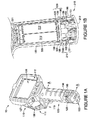
- Figure 1A is a perspective view of a thermal imaging device 10, according to some embodiments of the present invention.
- Figure 1A illustrates a housing of thermal imaging device 10 including a first portion 110 and a second portion 120.
- the housing may be formed from one or more injection molded, hard plastic parts, which lend structural support to all the components of device 10 that are necessary to capture infrared images, and which provide an effective handling interface for a user of device 10.
- Figure 1A further illustrates first portion 110 of the housing including a first side 111, a second side 112, which is opposite first side 111, and a third side 115, from which second portion 120 of the housing extends.
- second portion 120 of the housing extends toward a terminal end 123 of thermal imaging device 10 and forms a handle for device 10, while first portion 110 of the housing contains a thermal imaging assembly of device 10.
- the imaging assembly includes those elements, known to those skilled in the art, that are typically necessary for thermal imaging, such as a thermal sensor assembly, for example, a microbolometer thermal detector, a lens assembly and a printed circuit board assembly, for example, including one or more signal processors.
- a focusing assembly 130 is shown mounted to first side 111 of housing first portion 110, and a display 150 mounted to a second side 112, so that, when a user of device 10 grasps housing second portion 120, as a handle, the user may point focus assembly 130 toward a scene and simultaneously view a captured thermal image of the scene on display 150.
- An end 128 of housing second portion 120 is shown including an aperture 125 extending therethrough; a handling strap (not shown) may be secured, at one end thereof, to aperture 125, and, at another end thereof, to a loop member 127, which is shown mounted to housing first portion 110.
- Device 10 further includes various actuation elements and/or buttons, a mounting of which may be ergonomically arranged, for example, as is described in co-pending and commonly-assigned U.S. patent application serial number 11/873,699 .
- Figure 1B is a cross-section view, taken along line A-A of Figure 1A , according to some embodiments.
- Figure 1B illustrates a pair of battery cells 312 contained within housing second portion 120 and being electrically connected to the imaging assembly of device 10, via an electrical contact 321.
- battery cells 312 are included in a replaceable battery pack, for example, battery pack 200, which is shown in Figures 2 and 3 .
- Figures 1B , 2 and 3 illustrate battery pack 200 including a sidewall 325, which contains battery cells 312, and electrical contact 321, for example, being formed in sidewall 325.
- battery pack 200 may be divided into two portions: a battery portion 220, which includes sidewall 325, battery cells 312 and electrical contact 321, and a base portion 210, on which battery portion 220 is mounted.
- a battery portion 220 which includes sidewall 325, battery cells 312 and electrical contact 321, and a base portion 210, on which battery portion 220 is mounted.
- base portion 210 engages with end 128, for example, as shown in Figure 1B , such that battery portion 120 is held within an interior of housing second portion 120, the interior of housing second portion 120 is sealed from an environment external thereto, electrical contact 321 is held in electrical connection with a mating connector of the imaging assembly of device 10, and base portion 210 protrudes outside the housing to form terminal end 123 of device 10.
- Figure 3 illustrates base portion 210 including an attachment mechanism 215, which is configured to engage with end 128 of housing second portion 120 and to be releasable therefrom.
- Figure 1B illustrates the engagement of attachment mechanism 215, with housing second portion 120, via a pair of opposing projections 150; each projection 150 spring loaded, or biased, by a corresponding spring member 153 of attachment mechanism 215, in order to engage with a corresponding recess 105, which is formed in an inner surface of end 128 of housing second portion 120.
- Figure 1B further illustrates attachment mechanism 215 including a pair of opposing release members 151.
- attachment mechanism 215 is shown including opposing pairs of projections 150, release members 151 and spring members 153, alternate embodiments of the invention may include different configurations of attachment mechanism, for example, which including only a single projection 150, release member 151 and spring member 153.
- Figures 1A-B further illustrate device 10 including orientation markers in the form of two ridges 190, 195; ridge 190 is shown formed on end 128 of housing second portion 120, and ridge 195 on one of release members 151.
- ridges 190 and 195 serve as both a tactile and a visible reference to help the user to properly orient battery pack 200, when inserting battery pack 200 into housing second portion 120 for engagement with end 128. The proper orientation is necessary in order to align electrical contact 321 of battery pack with the mating connector of the imaging assembly, within the housing, when attachment mechanism 125 engages end 128.
- surfaces 108 and 308 of housing end 128 and battery pack 200 are identified.
- surfaces 108 and 308 come together to form an interface that seals the interior of the housing from an environment external thereto.
- Surface 308 may be an exposed portion of a seal and/or shock absorbing member, for example, which is formed on base portion 210 of battery pack 200, as will be described in greater detail below.
- surface 108 is relatively hard and non-deformable and is continuous about an entire perimeter of inside of housing end 128, for example, having been formed without any seam, mold parting line, or any other similar discontinuity that could form a leak path at the seal interface.
- at least end 128, if not a significant portion of housing second portion 120, is molded as a single piece.
- terminal end 123 of device 10 may be subject to impact loading, if device 10 is mishandled, for example, dropped; such impact loading could damage the housing of device 10 and/or the components contained within the housing of device 10.
- a shock absorbing member is included in battery pack 200.
- an exposed face 212 of base portion 210 of battery pack 200 comprises the shock absorbing member.
- a layer of shock absorbing material, which includes face 212, is formed over a surface of a part of base portion 210.
- a thermoplastic polyester elastomer material i.e. TPC-ET
- TPC-ET thermoplastic polyester elastomer material
- thermoplastic polyester elastomers include Hytrel®, available from DuPontTM, and Riteflex® available from Ticona Engineering Polymers. Alternately, or in addition, a shock absorbing member may be integrated into an internal structure of battery pack 200.
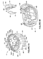
- Figure 4A is a perspective view of battery portion 220 of battery pack 200, according to some embodiments, having been separated from base portion 210; and Figure 4B is an exploded perspective view of base portion 210, according to some embodiments.
- Figure 4A illustrates sidewall 325 of battery portion 220 including opposing first and second outer surfaces 401, 402, and attachment posts 451 that protrude from first outer surface 401.
- Figure 4B illustrates base portion 210 including a face 411 configured to interface with first outer surface 401 of battery portion 220, when battery pack 200 is assembled, as shown in Figures 2 and 3 ; receptacles 415 are shown extending from face 411 and into base portion 210, wherein each receptacle 415 is sized and positioned to receive a corresponding attachment post 451 of battery portion 220 for the assembly of battery pack 200.
- one of attachment posts 451 includes a unique profile for mating with only one of receptacles 415, so that a proper orientation of battery portion 220 with respect to base portion 210 is assured in the assembly of battery pack 200.
- Figure 4B further illustrates fasteners 45 (i.e. screws) positioned adjacent to face 212 of base portion 210, where guide bores 35 ( Figure 2 ) are formed to receive fasteners 45. Openings into guide bores 35 may be seen in Figure 2 , and dashed lines in Figure 4B show each bore 35 extending within base portion 210, to a corresponding internal opening 435. According to the illustrated embodiment, an end of each fastener 45, when inserted into the corresponding guide bore 35, extends through the corresponding internal opening 435 in order to mate with internal threads of a corresponding post 451, which has been inserted into a corresponding receptacle 415 of base portion 210, when battery pack is assembled 200.
- fasteners 45 i.e. screws
- face 411 of base portion 210 includes a member for shock absorbing and/or sealing, for example, being formed from an elastomer material, such as the thermoplastic elastomer know as Versollan (available from GLS Corporation).
- Figure 5A is an enlarged perspective view of base portion 210, according to some preferred embodiments, wherein a face 511 thereof includes both a seal member and a relatively hard and non-deformable surface.
- Figure 5A illustrates the seal member including a central portion 513, an outer perimeter ridge 513A and a plurality of perimeter ridges 513B, each of which surrounds a corresponding receptacle 415.
- outer perimeter ridge 513A of the seal member forms surface 308, which surrounds a third outer surface 403 of battery portion sidewall 325, in close proximity to first outer surface 401, when battery pack 200 is assembled, and which seals against surface 108 within end 128 of housing second portion 120 ( Figure 2 ), when attachment mechanism 215 of battery pack 200 is engaged with end 128.
- each perimeter ridge 513B seals around the corresponding attachment post 451 and against first outer surface 401 of sidewall 325, when fasteners 45 are mated therewith in the assembled battery pack 200.
- Figure 5A further illustrates a plurality of relatively hard and non-deformable surfaces 512A, which are approximately coplanar with central portion 513 of the seal member, and an outer relatively hard and non-deformable surface 512B, that surrounds outer perimeter ridge 513A of the seal member.
- surfaces 512A form a relatively hard and non-deformable interface between base portion 210 and first outer surface 401 of battery portion 220, which, by providing a 'hard stop', limits a compression of the seal member when battery portion 220 is secured to base portion 210, for example, via the tightening of fasteners 45 within posts 451.
- This 'hard stop' can prevent an over-tightening of fasteners 45, that could overload and potentially damage posts 451, and can further control a tolerance of the assembly of battery pack 200, for example, with respect to the location of electrical contact 321 relative to attachment mechanism 215, so that both contact 321 and attachment mechanism 215 operatively couple with device 10, when a user inserts battery pack into housing second portion 120, as previously described.
- outer surface 512B may abut surface 108 to also provide a 'hard stop', at the interface between battery pack 200 and housing end 128, when attachment mechanism 125 engages with end 128.
- the seal member of face 511 is formed over a portion of a surface of a part 41 of base portion 210, preferably by a two-shot molding process or by an over-molding process, so as to leave other portions of the surface exposed as the aforementioned relatively hard and non-deformable surfaces 512A, 512B.
- Part 41 may be formed from a relatively hard plastic, such as a polycarbonate - acrylonitrile butadiene styrene blend (PC-ABS), for example, available from Sabic Innovative Plastics, and the seal member from an elastomer, such as the aforementioned thermoplastic elastomer.
- the seal member may be separately formed as a piece part, which is subsequently coupled in between the surface of part 41 and first outer surface 401 of battery portion sidewall 325.
- base portion 210 is shown including both first part 41 and a second part 42, which, when brought together, for example, as illustrated in Figure 3 , hold attachment mechanism 215 in place.
- Figure 4B illustrates a sidewall of each of parts 41 and 42 having opposing openings 419, 429 and an edge 416 and 426, respectively; the contours of edges 416, 426 mate with one another to align opposing openings 419 of first part 41 with opposing openings 429 of second part 42.
- Second part 42 may be formed from a relatively hard plastic, such as PC-ABS or, according to some preferred embodiments, may be formed from a thermoplastic polyester elastomer, such as the aforementioned Hytrel® or Riteflex®, in order to function as a shock absorbing member, as previously described. If second part 42 is formed from the relatively hard plastic, a layer of shock absorbing material may extend over a surface of part 42 to form exposed face 212.
- a relatively hard plastic such as PC-ABS or, according to some preferred embodiments, may be formed from a thermoplastic polyester elastomer, such as the aforementioned Hytrel® or Riteflex®, in order to function as a shock absorbing member, as previously described. If second part 42 is formed from the relatively hard plastic, a layer of shock absorbing material may extend over a surface of part 42 to form exposed face 212.
- each of opposing openings 419 of first part 41 surround a corresponding projection 150 of attachment mechanism 215, and that each of opposing openings 429 of second part 42 surround a corresponding release member 151 of attachment mechanism 215.
- each projection 150 and the corresponding release member 151 are integrally formed, for example, from a hard plastic material such as an acetal copolymer, for example, Celcon M90 (available from Ticona Engineering Polymers), which may be selected for its relatively lubricious surface properties.
- Fasteners 45 in addition to securing battery portion 220 to base portion 210, secure attachment mechanism 215 in place, by securing first and second parts 41, 42 together around attachment mechanism 215.
- spring member 153 is shown formed as a leaf spring and a slot 535 is shown formed within second part 42 to receive a first end 51 of spring member 153, such that, when a second end 52 of spring member 153 is coupled with projection 150, and, when release member 151 is placed within opening 429 of second part 42, spring member 153 may be compressed between projection 150 and second part 42, for example, as is shown in the cross-section of Figure 1B .
- Spring member 153 may be formed from stainless steel, for example, 301 stainless, having a thickness of approximately 0.4 mm.
- Figures 4B and 5A-B further illustrate each release member 151 including shoulders 456, which extend from either side of the corresponding projection 150, and portions 465 of edge 416 of first part 41, that are configured to abut shoulders 456, when battery pack 200 is assembled, according to some embodiments, so as to hold each projection 150 in a predetermined position.
- the predetermined position ensures that projections 150 are located at an appropriate distance from face 411/511 of base portion 210 so that, when projections 150 are received by recesses 105 of the housing of thermal imaging device 10 ( Figure 1 B) , electrical contact 321 of battery portion 220 is operatively connected with the imaging assembly of device 10, and the seal member of face 411/511 is sufficiently compressed against surface 108 within end 128 of housing second portion 120, in order to seal the interior of the housing from an environment external thereto.
- the predetermined position in conjunction with the compression properties of the seal interface, also allows projections 150 to move past a lip of recesses 105, as battery pack 200 is being inserted into end 128 of housing second portion 120, and then to 'snap' into engagement with recesses 105.
- end 128 of housing second portion 120 may include a seal member located to interface with a relatively hard and non-deformable surface of replaceable battery pack 200, when attachment mechanism 215 engages end 128.
- a seal member may be employed in conjunction with, or as an alternative to, surface 308 or perimeter ridge 513A of the above-described battery pack seal member, although it is preferred that replaceable battery pack 200 include a seal member, in order to introduce a new seal member each time the battery pack is replaced.
- one or more radially projecting seal members may be employed by alternate embodiments of the present invention.
- a seal member may project radially from third outer surface 403 of battery portion sidewall 325 to seal against a relatively hard and non-deformable inner surface 108' of housing end 128, when attachment mechanism 215 engages end 128 and surface 512B is in proximity to surface 108.
- a radial seal member may be formed around each attachment post 451 or within each receptacle 415.
Landscapes
- Physics & Mathematics (AREA)
- General Physics & Mathematics (AREA)
- Spectroscopy & Molecular Physics (AREA)
- Battery Mounting, Suspending (AREA)
- Studio Devices (AREA)
- Camera Bodies And Camera Details Or Accessories (AREA)
Claims (13)
- Wärmebildvorrichtung (10), umfassend:Ein Gehäuse (110, 120), das eine Abbildungsanordnung der Vorrichtung enthält; undeinen austauschbaren Batteriepack (200), der eine Seitenwand (325), ein stoßdämpfendes Element, einen Befestigungsmechanismus (215) und einen elektrischen Kontakt (321) einschließt, wobei der austauschbare Batteriepack (200) wenigstens eine Batteriezelle (312) enthält, die an den elektrischen Kontakt (321) gekoppelt ist und der Befestigungsmechanismus (215) konfiguriert ist, in ein Ende des Gehäuses (110, 120) einzurasten und davon lösbar zu sein;wobei, wenn der Befestigungsmechanismus (215) des Batteriepacks (200) in das Ende des Gehäuses (110, 120) einrastet, der elektrische Kontakt (321) des Batteriepacks (200) in elektrischer Verbindung mit der Abbildungsanordnung, innerhalb des Gehäuses (110, 120), gehalten wird und ein Abschnitt des Batteriepacks (200) eine Anschlussseite der Vorrichtung, außerhalb des Gehäuses (110, 120), bildet;wobei das stoßdämpfende Element des austauschbaren Batteriepacks eine Materialschicht umfasst, die über den Abschnitt des Batteriepacks gebildet ist, der die Anschlussseite der Vorrichtung bildet, undwenn der Befestigungsmechanismus (215) aus der Rastung mit dem Ende des Gehäuses (110, 120) gelöst wird, ist eine Ganzheit des austauschbaren Batteriepacks (200) vollends von der Vorrichtung trennbar.
- Wärmebildvorrichtung (10) nach Anspruch 1, wobei die Materialschicht ein thermoplastisches Polyesterelastomer umfasst.
- Wärmebildvorrichtung (10) nach Anspruch 1 oder Anspruch 2, wobei das stoßdämpfende Element außerdem dazu dient, einen Innenraum des Gehäuses (110, 120) von einer Umgebung außerhalb davon abzudichten, wenn der Befestigungsmechanismus (215) des Batteriepacks (200) in das Ende des Gehäuses (110, 120) einrastet.
- Wärmebildvorrichtung (10) nach einem der vorhergehenden Ansprüche, wobei:Das Ende des Gehäuses (110, 120) eine Aussparung (105) einschließt, die an einer Innenfläche (128) davon gebildet ist;der Befestigungsmechanismus (215) des austauschbaren Batteriepacks (200) einen Vorsprung (150) und ein Auslöseelement (151) umfasst, wobei der Vorsprung (150) federbelastet ist und das Auslöseelement (151) an den Vorsprung (150) gekoppelt ist;der Vorsprung (150) konfiguriert ist, von der Aussparung (105) des Gehäuses, zur Rastung damit, aufgenommen zu werden; unddas Auslöseelement (151) ist derart positioniert, dass ein Finger einer Hand gegen das Auslöseelement (151) drücken kann, um den Vorsprung (150) gegen die Federlast zu bewegen, damit der Vorsprung (150) von der Aussparung (105) des Gehäuses (110, 120) ausgekuppelt wird, um den Befestigungsmechanismus (215) aus der Rastung mit dem Ende des Gehäuses (110,120) zu lösen.
- Wärmebildvorrichtung (10) nach einem der vorhergehenden Ansprüche, wobei:Das Gehäuse einen ersten Abschnitt (110) und einen zweiten Abschnitt (120) einschließt, der erste Abschnitt (110) des Gehäuses die Abbildungsanordnung enthält und eine erste Seite (111), an die eine Fokussierungsanordnung der Vorrichtung montiert ist, eine zweite Seite (112), die der ersten Seite (111) gegenüber liegt und, an die eine Anzeige der Vorrichtung montiert ist, und eine dritte Seite (115) einschließt, die sich zwischen den ersten und zweiten Seiten (111,112) erstreckt;sich der zweite Abschnitt (120) des Gehäuses aus der dritten Seite (115) des ersten Abschnitts (110) des Gehäuses heraus erstreckt, um einen Griff der Vorrichtung zu bilden, und das Ende des Gehäuses einschließt, in das der Befestigungsmechanismus (215) des austauschbaren Batteriepacks (200) einrastet.
- Wärmebildvorrichtung (10) nach einem der vorhergehenden Ansprüche, wobei das Ende des Gehäuses (110, 120) und der Befestigungsmechanismus (215) des austauschbaren Batteriepacks jeweils eine Orientierungsmarkierung (190, 195) einschließen, um eine einwandfreie Orientierung des Batteriepacks (200) zur Rastung mit dem Ende des Gehäuses (110, 120) zu erleichtern.
- Wärmebildvorrichtung (10) nach einem der vorhergehenden Ansprüche, wobei:Der austauschbare Batteriepack (200) einen Batterieabschnitt (220) und einen Basisabschnitt (210) einschließt, wobei der Batterieabschnitt (220) die Seitenwand (325) einschließt und der Basisabschnitt eine erste Fläche und eine zweite Fläche, gegenüber der ersten Fläche, einschließt;der Basisabschnitt (210) des Batteriepacks (200) ferner ein Dichtungselement einschließt, das direkt daran geformt ist und die Seitenwand (325) des Batterieabschnitts (220) des Batteriepacks (200) umgibt; undwenn der Befestigungsmechanismus (215) des Batteriepacks (200) in das Ende des Gehäuses (110, 120) einrastet, wird der Batterieabschnitt (220) des Batteriepacks (200) innerhalb des Gehäuses (110, 120) festgehalten und das Dichtungselement dichtet gegen eine Oberfläche innerhalb des Endes des Gehäuses (110, 120) ab, um einen Innenraum des Gehäuses von einer Umgebung außerhalb davon abzudichten.
- Wärmebildvorrichtung (10) nach Anspruch 7, wobei die erste Fläche des Basisabschnitts (210) ein Dichtungselement umfasst.
- Wärmebildvorrichtung (10) nach Anspruch 7, wobei:Die Seitenwand (325) des Batterieabschnitts (220) des austauschbaren Batteriepacks (200) eine erste Außenfläche (401) und eine zweite Außenfläche (402), gegenüber der ersten Außenfläche (401) einschließt;der Batterieabschnitt (220) ferner wenigstens einen Befestigungspfosten (451) einschließt, der aus der ersten Außenfläche (401) der Seitenwand (325) hervorsteht;der Basisabschnitt (210) des austauschbaren Batteriepacks (200) ferner wenigstens eine Steckbuchse (415) einschließt, die sich von der ersten Fläche (411) davon in Richtung der zweiten Fläche (212) davon erstreckt, wobei jede der wenigstens einen Steckbuchse (415) konfiguriert ist, einen entsprechenden Befestigungspfosten (451) aufzunehmen; unddas Dichtungselement des Basisabschnitts (210) eine Umfangsfurche einschließt, die jede der wenigstens einen Steckbuchse (415) und den entsprechenden darin aufgenommenen Befestigungspfosten (451) umgibt.
- Wärmebildvorrichtung (10) nach einem der Ansprüche 7 bis 9, wobei die erste Fläche (411) des Basisabschnitts (210) des Batteriepacks (200) einen ersten Abschnitt und einen zweiten Abschnitt umfasst, wobei der erste Abschnitt durch das Dichtungselement gebildet wird und der zweite Abschnitt relativ hart und nicht verformbar ist, um eine relativ harte und nicht verformbare Schnittstelle mit dem Batterieabschnitt (220) des Batteriepacks (200) zu bilden.
- Wärmebildvorrichtung (10) nach einem der Ansprüche 7 bis 10, wobei:Das Dichtungselement des Basisabschnitts (210) des austauschbaren Batteriepacks (200) eine äußere Umfangsfurche (513A) einschließt, wobei die äußere Umfangsfurche (513A) die Seitenwand (325) des Batterieabschnitts (220) des Batteriepacks (200) umgibt; unddas Ende des Gehäuses eine relativ harte und nicht verformbare Oberfläche (108) einschließt, gegen welche die äußere Umfangsfurche (513) des Dichtungselements anstößt, wenn der Befestigungsmechanismus (215) des Basisabschnitts (210) in das Ende des Gehäuses einrastet.
- Wärmebildvorrichtung nach Anspruch 11, wobei die erste Fläche (411) des Basisabschnitts (210) ferner eine relativ harte und nicht verformbare Oberfläche umfasst, die positioniert ist, ebenfalls an die relativ harte und nicht verformbare Oberfläche (108) des Endes des Gehäuses anzustoßen, wenn der Befestigungsmechanismus (215) des Basisabschnitts (210) in das Ende des Gehäuses einrastet.
- Wärmebildvorrichtung nach einem der Ansprüche 7 bis 12, wenn vom Anspruch 4 abhängig, wobei:Das Dichtungselement des Basisabschnitts (210) des Batteriepacks (200) wenigstens einen Abschnitt der ersten Fläche (411) des ersten Teils des Basisabschnitts (210) bildet;der Vorsprung (150) des Befestigungsmechanismus (215) integral mit dem Auslöseelement (151) des Befestigungsmechanismus (215) gebildet ist;der Basisabschnitt (210) des Batteriepacks (200) ferner eine Seitenwand einschließt, die sich zwischen den ersten und zweiten Flächen (411, 212) erstreckt, wobei die Seitenwand eine Öffnung und einen Rand in der Nähe der Öffnung einschließt, wobei die Öffnung den Vorsprung (150) des Befestigungsmechanismus (215) umgibt; unddas Auslöseelement (151) eine Schulter (456) einschließt, die sich ab jeder Seite des Vorsprungs (150) erstreckt und gegen die ein Abschnitt des Randes des Basisabschnitts (210) anstößt, um den Vorsprung (150) in einer vorbestimmten Position zu halten, wobei sich die vorbestimmte Position in einem Abstand von der ersten Fläche (411) des Basisabschnitts (210) befindet, sodass, wenn der Vorsprung (150) von der Aussparung des Gehäuses, zwecks Rastung damit, aufgenommen wird, der elektrische Kontakt (321) des Batterieabschnitts (200) in elektrischer Verbindung mit der Bildanordnung gehalten wird, und eine Kompression des Dichtungselements, gegen die Oberfläche innerhalb des Endes des Gehäuses, ist ausreichend, um den Innenraum des Gehäuses von einer dazu äußeren Umgebung abzudichten.
Applications Claiming Priority (1)
| Application Number | Priority Date | Filing Date | Title |
|---|---|---|---|
| US12/504,962 US7867019B1 (en) | 2009-07-17 | 2009-07-17 | Thermal imaging device with a battery pack with a shock absorber |
Publications (3)
| Publication Number | Publication Date |
|---|---|
| EP2278288A2 EP2278288A2 (de) | 2011-01-26 |
| EP2278288A3 EP2278288A3 (de) | 2012-01-18 |
| EP2278288B1 true EP2278288B1 (de) | 2016-11-16 |
Family
ID=43014322
Family Applications (1)
| Application Number | Title | Priority Date | Filing Date |
|---|---|---|---|
| EP10251275.3A Active EP2278288B1 (de) | 2009-07-17 | 2010-07-16 | Tragbare Vorrichtung zur thermischen Abbildung und zugehörige austauschbare Batteriepacks |
Country Status (3)
| Country | Link |
|---|---|
| US (2) | US7867019B1 (de) |
| EP (1) | EP2278288B1 (de) |
| CN (1) | CN101958407B (de) |
Families Citing this family (26)
| Publication number | Priority date | Publication date | Assignee | Title |
|---|---|---|---|---|
| US8235590B2 (en) * | 2008-08-21 | 2012-08-07 | Fluke Corporation | Thermal instrument engine |
| JP2011233410A (ja) * | 2010-04-28 | 2011-11-17 | Makita Corp | 電気機器システム、及びそれに使用されるアダプタ |
| US9723229B2 (en) | 2010-08-27 | 2017-08-01 | Milwaukee Electric Tool Corporation | Thermal detection systems, methods, and devices |
| CN203705055U (zh) | 2011-03-15 | 2014-07-09 | 米沃奇电动工具公司 | 热像仪 |
| WO2013009148A2 (ko) * | 2011-07-13 | 2013-01-17 | 주식회사 엘지화학 | 원통형 이차 전지 |
| DE102011086374A1 (de) | 2011-11-15 | 2013-05-16 | Siemens Aktiengesellschaft | Hochtemperatur-Energiespeicher mit Rekuperator |
| US8979110B2 (en) * | 2012-03-16 | 2015-03-17 | Specialized Bicycle Components, Inc. | Bicycle with battery mount |
| US9415459B2 (en) | 2012-04-06 | 2016-08-16 | Illinois Tool Works Inc. | Welding systems having non-contact temperature measurement systems |
| US9266182B2 (en) | 2012-04-06 | 2016-02-23 | Illinois Tools Works Inc. | Welding torch with a temperature measurement device |
| US9791896B2 (en) | 2012-07-13 | 2017-10-17 | Symbol Technologies, Llc | Device and method for performing a functionality |
| US9202095B2 (en) | 2012-07-13 | 2015-12-01 | Symbol Technologies, Llc | Pistol grip adapter for mobile device |
| US10794769B2 (en) | 2012-08-02 | 2020-10-06 | Milwaukee Electric Tool Corporation | Thermal detection systems, methods, and devices |
| USD686155S1 (en) * | 2012-12-13 | 2013-07-16 | Surefire Llc | Battery pack for a portable light |
| USD763261S1 (en) | 2013-04-30 | 2016-08-09 | Symbol Technologies, Llc | Ergonomic mobile computing device |
| US20160033336A1 (en) * | 2014-07-30 | 2016-02-04 | Milwaukee Electric Tool Corporation | Thermal detection systems, methods, and devices |
| USD807374S1 (en) | 2015-07-21 | 2018-01-09 | Symbol Technologies, Llc | Bezel component for a mobile computer device |
| USD781860S1 (en) | 2015-07-21 | 2017-03-21 | Symbol Technologies, Llc | Mobile computer device |
| US9697393B2 (en) | 2015-11-20 | 2017-07-04 | Symbol Technologies, Llc | Methods and systems for adjusting mobile-device operating parameters based on housing-support type |
| US11021177B2 (en) | 2016-10-20 | 2021-06-01 | Rail Vision Ltd | System and method for object and obstacle detection and classification in collision avoidance of railway applications |
| EP3706188B1 (de) * | 2017-10-30 | 2023-03-08 | Hangzhou Hikmicro Sensing Technology Co., Ltd. | Handhaltbare infrarot-photogrammetrische vorrichtung |
| WO2019085566A1 (zh) | 2017-10-30 | 2019-05-09 | 杭州海康威视数字技术股份有限公司 | 一种热成像设备 |
| US10381851B2 (en) * | 2017-12-22 | 2019-08-13 | Datalogic Ip Tech S.R.L. | Battery support for a scanning device |
| USD930729S1 (en) * | 2018-12-31 | 2021-09-14 | Flir Systems Ab | Camera |
| US11451700B2 (en) | 2019-03-06 | 2022-09-20 | Aob Products Company | Game camera having camera control module |
| USD918210S1 (en) | 2019-04-04 | 2021-05-04 | Zebra Technologies Corporation | Data capture device |
| US11705600B2 (en) | 2019-09-06 | 2023-07-18 | Snap-On Incorporated | Electronic torque wrench with interchangeable battery |
Citations (1)
| Publication number | Priority date | Publication date | Assignee | Title |
|---|---|---|---|---|
| WO2001065834A2 (en) * | 2000-03-02 | 2001-09-07 | Mine Safety Appliances Company | Thermal imaging camera |
Family Cites Families (21)
| Publication number | Priority date | Publication date | Assignee | Title |
|---|---|---|---|---|
| US3041317A (en) * | 1960-05-02 | 1962-06-26 | Du Pont | Fluorocarbon sulfonyl fluorides |
| US4005605A (en) * | 1974-07-22 | 1977-02-01 | Mikron Instrument Company, Inc. | Remote reading infrared thermometer |
| JPS56501138A (de) * | 1979-09-12 | 1981-08-13 | ||
| US4266036A (en) * | 1979-10-23 | 1981-05-05 | Diamond Shamrock Corporation | Recovery of polymeric cation exchange materials for reuse by converting by reaction to the precursor form |
| US4358545A (en) * | 1980-06-11 | 1982-11-09 | The Dow Chemical Company | Sulfonic acid electrolytic cell having flourinated polymer membrane with hydration product less than 22,000 |
| JPS5941973U (ja) * | 1982-09-09 | 1984-03-17 | 三洋電機株式会社 | 電池パツク |
| US4940525A (en) * | 1987-05-08 | 1990-07-10 | The Dow Chemical Company | Low equivalent weight sulfonic fluoropolymers |
| US5468574A (en) * | 1994-05-23 | 1995-11-21 | Dais Corporation | Fuel cell incorporating novel ion-conducting membrane |
| US5736726A (en) * | 1996-03-29 | 1998-04-07 | Telxon Corporation | Portable data collection device having removable handle and battery |
| US5934938A (en) * | 1996-08-20 | 1999-08-10 | Chrysler Corporation | Split seal retainer for an electrical connector |
| US6248469B1 (en) * | 1997-08-29 | 2001-06-19 | Foster-Miller, Inc. | Composite solid polymer electrolyte membranes |
| US20050160272A1 (en) * | 1999-10-28 | 2005-07-21 | Timecertain, Llc | System and method for providing trusted time in content of digital data files |
| TW501326B (en) * | 2001-01-10 | 2002-09-01 | Tai-He Yang | Electric equipment with backup battery-stand powered by host machine power source |
| CN100414275C (zh) * | 2001-05-07 | 2008-08-27 | 前视红外系统股份公司 | 手持红外摄像机 |
| CN1276525C (zh) * | 2001-07-24 | 2006-09-20 | 索尼公司 | 用于防止将待装器件错误地装入主体侧设备的方法、待装器件以及电池组 |
| KR100932820B1 (ko) * | 2001-07-25 | 2009-12-21 | 소니 가부시끼 가이샤 | 배터리 장치 |
| JP3722067B2 (ja) * | 2002-01-29 | 2005-11-30 | 松下電器産業株式会社 | 電磁振動体を用いた電池駆動機器 |
| WO2005086632A2 (en) * | 2004-01-23 | 2005-09-22 | The University Of North Carolina At Chapel Hill | Liquid materials for use in electrochemical cells |
| US7199832B2 (en) * | 2004-10-01 | 2007-04-03 | Daniel Oran | Portable photographic device and grip with integrated controls for single handed use |
| US7250603B1 (en) * | 2006-03-24 | 2007-07-31 | Draeger Safety, Inc. | Crawling handle for thermal imaging camera |
| JP5233163B2 (ja) * | 2007-05-16 | 2013-07-10 | ソニー株式会社 | バッテリパック |
-
2009
- 2009-07-17 US US12/504,962 patent/US7867019B1/en active Active
-
2010
- 2010-07-16 EP EP10251275.3A patent/EP2278288B1/de active Active
- 2010-07-16 CN CN201010232774.9A patent/CN101958407B/zh active Active
- 2010-12-22 US US12/976,399 patent/US7959458B2/en active Active
Patent Citations (1)
| Publication number | Priority date | Publication date | Assignee | Title |
|---|---|---|---|---|
| WO2001065834A2 (en) * | 2000-03-02 | 2001-09-07 | Mine Safety Appliances Company | Thermal imaging camera |
Also Published As
| Publication number | Publication date |
|---|---|
| EP2278288A3 (de) | 2012-01-18 |
| US7867019B1 (en) | 2011-01-11 |
| CN101958407B (zh) | 2014-12-17 |
| US7959458B2 (en) | 2011-06-14 |
| CN101958407A (zh) | 2011-01-26 |
| US20110091758A1 (en) | 2011-04-21 |
| US20110014812A1 (en) | 2011-01-20 |
| EP2278288A2 (de) | 2011-01-26 |
Similar Documents
| Publication | Publication Date | Title |
|---|---|---|
| US7959458B2 (en) | Thermal imaging device with a battery pack with a seal member molded directly thereon | |
| US12143140B2 (en) | Docking sleeve with electrical adapter | |
| US9954330B2 (en) | Docking sleeve with electrical adapter | |
| US8025236B2 (en) | Cover for a portable device having grip portions | |
| US20160065702A1 (en) | Docking sleeve with electrical adapter | |
| US7992787B2 (en) | Reed switch mechanism for a portable terminal | |
| KR102169428B1 (ko) | 전기 어댑터를 갖춘 도킹 슬리브 | |
| KR101122943B1 (ko) | 배터리 장치 및 전자 기기 | |
| US10707457B2 (en) | Battery case and robot having the same | |
| JP2005315989A (ja) | アクセサリーシュー装置および電子機器並びにアクセサリー | |
| CN107810461B (zh) | 含电气转接头之对接套 | |
| CN213213572U (zh) | 电子设备保护壳 | |
| JP5798952B2 (ja) | 赤外線検出装置 |
Legal Events
| Date | Code | Title | Description |
|---|---|---|---|
| PUAI | Public reference made under article 153(3) epc to a published international application that has entered the european phase |
Free format text: ORIGINAL CODE: 0009012 |
|
| AK | Designated contracting states |
Kind code of ref document: A2 Designated state(s): AL AT BE BG CH CY CZ DE DK EE ES FI FR GB GR HR HU IE IS IT LI LT LU LV MC MK MT NL NO PL PT RO SE SI SK SM TR |
|
| AX | Request for extension of the european patent |
Extension state: BA ME RS |
|
| PUAL | Search report despatched |
Free format text: ORIGINAL CODE: 0009013 |
|
| AK | Designated contracting states |
Kind code of ref document: A3 Designated state(s): AL AT BE BG CH CY CZ DE DK EE ES FI FR GB GR HR HU IE IS IT LI LT LU LV MC MK MT NL NO PL PT RO SE SI SK SM TR |
|
| AX | Request for extension of the european patent |
Extension state: BA ME RS |
|
| RIC1 | Information provided on ipc code assigned before grant |
Ipc: G01J 5/00 20060101ALN20111212BHEP Ipc: G01J 5/04 20060101ALI20111212BHEP Ipc: G01J 5/02 20060101AFI20111212BHEP |
|
| 17P | Request for examination filed |
Effective date: 20120718 |
|
| RIC1 | Information provided on ipc code assigned before grant |
Ipc: G01J 5/00 20060101ALN20151008BHEP Ipc: G01J 5/04 20060101ALI20151008BHEP Ipc: G01J 5/02 20060101AFI20151008BHEP |
|
| 17Q | First examination report despatched |
Effective date: 20151208 |
|
| RIC1 | Information provided on ipc code assigned before grant |
Ipc: G01J 5/04 20060101ALI20160509BHEP Ipc: G01J 5/00 20060101ALN20160509BHEP Ipc: G01J 5/02 20060101AFI20160509BHEP |
|
| GRAP | Despatch of communication of intention to grant a patent |
Free format text: ORIGINAL CODE: EPIDOSNIGR1 |
|
| INTG | Intention to grant announced |
Effective date: 20160701 |
|
| GRAJ | Information related to disapproval of communication of intention to grant by the applicant or resumption of examination proceedings by the epo deleted |
Free format text: ORIGINAL CODE: EPIDOSDIGR1 |
|
| GRAR | Information related to intention to grant a patent recorded |
Free format text: ORIGINAL CODE: EPIDOSNIGR71 |
|
| GRAS | Grant fee paid |
Free format text: ORIGINAL CODE: EPIDOSNIGR3 |
|
| GRAA | (expected) grant |
Free format text: ORIGINAL CODE: 0009210 |
|
| INTC | Intention to grant announced (deleted) | ||
| RIC1 | Information provided on ipc code assigned before grant |
Ipc: G01J 5/02 20060101AFI20160929BHEP Ipc: G01J 5/04 20060101ALI20160929BHEP Ipc: G01J 5/00 20060101ALN20160929BHEP |
|
| AK | Designated contracting states |
Kind code of ref document: B1 Designated state(s): AL AT BE BG CH CY CZ DE DK EE ES FI FR GB GR HR HU IE IS IT LI LT LU LV MC MK MT NL NO PL PT RO SE SI SK SM TR |
|
| INTG | Intention to grant announced |
Effective date: 20161010 |
|
| REG | Reference to a national code |
Ref country code: GB Ref legal event code: FG4D |
|
| REG | Reference to a national code |
Ref country code: CH Ref legal event code: EP |
|
| REG | Reference to a national code |
Ref country code: IE Ref legal event code: FG4D |
|
| REG | Reference to a national code |
Ref country code: AT Ref legal event code: REF Ref document number: 846363 Country of ref document: AT Kind code of ref document: T Effective date: 20161215 |
|
| REG | Reference to a national code |
Ref country code: DE Ref legal event code: R096 Ref document number: 602010037986 Country of ref document: DE |
|
| REG | Reference to a national code |
Ref country code: DE Ref legal event code: R096 Ref document number: 602010037986 Country of ref document: DE |
|
| PG25 | Lapsed in a contracting state [announced via postgrant information from national office to epo] |
Ref country code: LV Free format text: LAPSE BECAUSE OF FAILURE TO SUBMIT A TRANSLATION OF THE DESCRIPTION OR TO PAY THE FEE WITHIN THE PRESCRIBED TIME-LIMIT Effective date: 20161116 |
|
| REG | Reference to a national code |
Ref country code: NL Ref legal event code: MP Effective date: 20161116 |
|
| REG | Reference to a national code |
Ref country code: LT Ref legal event code: MG4D |
|
| REG | Reference to a national code |
Ref country code: AT Ref legal event code: MK05 Ref document number: 846363 Country of ref document: AT Kind code of ref document: T Effective date: 20161116 |
|
| PG25 | Lapsed in a contracting state [announced via postgrant information from national office to epo] |
Ref country code: NL Free format text: LAPSE BECAUSE OF FAILURE TO SUBMIT A TRANSLATION OF THE DESCRIPTION OR TO PAY THE FEE WITHIN THE PRESCRIBED TIME-LIMIT Effective date: 20161116 Ref country code: SE Free format text: LAPSE BECAUSE OF FAILURE TO SUBMIT A TRANSLATION OF THE DESCRIPTION OR TO PAY THE FEE WITHIN THE PRESCRIBED TIME-LIMIT Effective date: 20161116 Ref country code: NO Free format text: LAPSE BECAUSE OF FAILURE TO SUBMIT A TRANSLATION OF THE DESCRIPTION OR TO PAY THE FEE WITHIN THE PRESCRIBED TIME-LIMIT Effective date: 20170216 Ref country code: LT Free format text: LAPSE BECAUSE OF FAILURE TO SUBMIT A TRANSLATION OF THE DESCRIPTION OR TO PAY THE FEE WITHIN THE PRESCRIBED TIME-LIMIT Effective date: 20161116 Ref country code: GR Free format text: LAPSE BECAUSE OF FAILURE TO SUBMIT A TRANSLATION OF THE DESCRIPTION OR TO PAY THE FEE WITHIN THE PRESCRIBED TIME-LIMIT Effective date: 20170217 |
|
| PG25 | Lapsed in a contracting state [announced via postgrant information from national office to epo] |
Ref country code: HR Free format text: LAPSE BECAUSE OF FAILURE TO SUBMIT A TRANSLATION OF THE DESCRIPTION OR TO PAY THE FEE WITHIN THE PRESCRIBED TIME-LIMIT Effective date: 20161116 Ref country code: PL Free format text: LAPSE BECAUSE OF FAILURE TO SUBMIT A TRANSLATION OF THE DESCRIPTION OR TO PAY THE FEE WITHIN THE PRESCRIBED TIME-LIMIT Effective date: 20161116 Ref country code: PT Free format text: LAPSE BECAUSE OF FAILURE TO SUBMIT A TRANSLATION OF THE DESCRIPTION OR TO PAY THE FEE WITHIN THE PRESCRIBED TIME-LIMIT Effective date: 20170316 Ref country code: FI Free format text: LAPSE BECAUSE OF FAILURE TO SUBMIT A TRANSLATION OF THE DESCRIPTION OR TO PAY THE FEE WITHIN THE PRESCRIBED TIME-LIMIT Effective date: 20161116 Ref country code: AT Free format text: LAPSE BECAUSE OF FAILURE TO SUBMIT A TRANSLATION OF THE DESCRIPTION OR TO PAY THE FEE WITHIN THE PRESCRIBED TIME-LIMIT Effective date: 20161116 Ref country code: ES Free format text: LAPSE BECAUSE OF FAILURE TO SUBMIT A TRANSLATION OF THE DESCRIPTION OR TO PAY THE FEE WITHIN THE PRESCRIBED TIME-LIMIT Effective date: 20161116 |
|
| REG | Reference to a national code |
Ref country code: FR Ref legal event code: PLFP Year of fee payment: 8 |
|
| PG25 | Lapsed in a contracting state [announced via postgrant information from national office to epo] |
Ref country code: DK Free format text: LAPSE BECAUSE OF FAILURE TO SUBMIT A TRANSLATION OF THE DESCRIPTION OR TO PAY THE FEE WITHIN THE PRESCRIBED TIME-LIMIT Effective date: 20161116 Ref country code: EE Free format text: LAPSE BECAUSE OF FAILURE TO SUBMIT A TRANSLATION OF THE DESCRIPTION OR TO PAY THE FEE WITHIN THE PRESCRIBED TIME-LIMIT Effective date: 20161116 Ref country code: CZ Free format text: LAPSE BECAUSE OF FAILURE TO SUBMIT A TRANSLATION OF THE DESCRIPTION OR TO PAY THE FEE WITHIN THE PRESCRIBED TIME-LIMIT Effective date: 20161116 Ref country code: RO Free format text: LAPSE BECAUSE OF FAILURE TO SUBMIT A TRANSLATION OF THE DESCRIPTION OR TO PAY THE FEE WITHIN THE PRESCRIBED TIME-LIMIT Effective date: 20161116 Ref country code: SK Free format text: LAPSE BECAUSE OF FAILURE TO SUBMIT A TRANSLATION OF THE DESCRIPTION OR TO PAY THE FEE WITHIN THE PRESCRIBED TIME-LIMIT Effective date: 20161116 |
|
| REG | Reference to a national code |
Ref country code: DE Ref legal event code: R097 Ref document number: 602010037986 Country of ref document: DE |
|
| PG25 | Lapsed in a contracting state [announced via postgrant information from national office to epo] |
Ref country code: IT Free format text: LAPSE BECAUSE OF FAILURE TO SUBMIT A TRANSLATION OF THE DESCRIPTION OR TO PAY THE FEE WITHIN THE PRESCRIBED TIME-LIMIT Effective date: 20161116 Ref country code: BG Free format text: LAPSE BECAUSE OF FAILURE TO SUBMIT A TRANSLATION OF THE DESCRIPTION OR TO PAY THE FEE WITHIN THE PRESCRIBED TIME-LIMIT Effective date: 20170216 Ref country code: BE Free format text: LAPSE BECAUSE OF FAILURE TO SUBMIT A TRANSLATION OF THE DESCRIPTION OR TO PAY THE FEE WITHIN THE PRESCRIBED TIME-LIMIT Effective date: 20161116 Ref country code: SM Free format text: LAPSE BECAUSE OF FAILURE TO SUBMIT A TRANSLATION OF THE DESCRIPTION OR TO PAY THE FEE WITHIN THE PRESCRIBED TIME-LIMIT Effective date: 20161116 |
|
| PLBE | No opposition filed within time limit |
Free format text: ORIGINAL CODE: 0009261 |
|
| STAA | Information on the status of an ep patent application or granted ep patent |
Free format text: STATUS: NO OPPOSITION FILED WITHIN TIME LIMIT |
|
| 26N | No opposition filed |
Effective date: 20170817 |
|
| PG25 | Lapsed in a contracting state [announced via postgrant information from national office to epo] |
Ref country code: SI Free format text: LAPSE BECAUSE OF FAILURE TO SUBMIT A TRANSLATION OF THE DESCRIPTION OR TO PAY THE FEE WITHIN THE PRESCRIBED TIME-LIMIT Effective date: 20161116 |
|
| REG | Reference to a national code |
Ref country code: CH Ref legal event code: PL |
|
| REG | Reference to a national code |
Ref country code: IE Ref legal event code: MM4A |
|
| PG25 | Lapsed in a contracting state [announced via postgrant information from national office to epo] |
Ref country code: LI Free format text: LAPSE BECAUSE OF NON-PAYMENT OF DUE FEES Effective date: 20170731 Ref country code: CH Free format text: LAPSE BECAUSE OF NON-PAYMENT OF DUE FEES Effective date: 20170731 Ref country code: IE Free format text: LAPSE BECAUSE OF NON-PAYMENT OF DUE FEES Effective date: 20170716 |
|
| PG25 | Lapsed in a contracting state [announced via postgrant information from national office to epo] |
Ref country code: LU Free format text: LAPSE BECAUSE OF NON-PAYMENT OF DUE FEES Effective date: 20170716 |
|
| REG | Reference to a national code |
Ref country code: FR Ref legal event code: PLFP Year of fee payment: 9 |
|
| PG25 | Lapsed in a contracting state [announced via postgrant information from national office to epo] |
Ref country code: MT Free format text: LAPSE BECAUSE OF NON-PAYMENT OF DUE FEES Effective date: 20170716 |
|
| PG25 | Lapsed in a contracting state [announced via postgrant information from national office to epo] |
Ref country code: MC Free format text: LAPSE BECAUSE OF FAILURE TO SUBMIT A TRANSLATION OF THE DESCRIPTION OR TO PAY THE FEE WITHIN THE PRESCRIBED TIME-LIMIT Effective date: 20161116 Ref country code: HU Free format text: LAPSE BECAUSE OF FAILURE TO SUBMIT A TRANSLATION OF THE DESCRIPTION OR TO PAY THE FEE WITHIN THE PRESCRIBED TIME-LIMIT; INVALID AB INITIO Effective date: 20100716 |
|
| PG25 | Lapsed in a contracting state [announced via postgrant information from national office to epo] |
Ref country code: CY Free format text: LAPSE BECAUSE OF NON-PAYMENT OF DUE FEES Effective date: 20161116 |
|
| PG25 | Lapsed in a contracting state [announced via postgrant information from national office to epo] |
Ref country code: MK Free format text: LAPSE BECAUSE OF FAILURE TO SUBMIT A TRANSLATION OF THE DESCRIPTION OR TO PAY THE FEE WITHIN THE PRESCRIBED TIME-LIMIT Effective date: 20161116 |
|
| PG25 | Lapsed in a contracting state [announced via postgrant information from national office to epo] |
Ref country code: TR Free format text: LAPSE BECAUSE OF FAILURE TO SUBMIT A TRANSLATION OF THE DESCRIPTION OR TO PAY THE FEE WITHIN THE PRESCRIBED TIME-LIMIT Effective date: 20161116 |
|
| PG25 | Lapsed in a contracting state [announced via postgrant information from national office to epo] |
Ref country code: AL Free format text: LAPSE BECAUSE OF FAILURE TO SUBMIT A TRANSLATION OF THE DESCRIPTION OR TO PAY THE FEE WITHIN THE PRESCRIBED TIME-LIMIT Effective date: 20161116 Ref country code: IS Free format text: LAPSE BECAUSE OF FAILURE TO SUBMIT A TRANSLATION OF THE DESCRIPTION OR TO PAY THE FEE WITHIN THE PRESCRIBED TIME-LIMIT Effective date: 20170316 |
|
| PGFP | Annual fee paid to national office [announced via postgrant information from national office to epo] |
Ref country code: DE Payment date: 20250729 Year of fee payment: 16 |
|
| PGFP | Annual fee paid to national office [announced via postgrant information from national office to epo] |
Ref country code: GB Payment date: 20250728 Year of fee payment: 16 |
|
| PGFP | Annual fee paid to national office [announced via postgrant information from national office to epo] |
Ref country code: FR Payment date: 20250725 Year of fee payment: 16 |