EP2278281B1 - Flow meter with reflector unit locked in relation to housing - Google Patents
Flow meter with reflector unit locked in relation to housing Download PDFInfo
- Publication number
- EP2278281B1 EP2278281B1 EP10156663.6A EP10156663A EP2278281B1 EP 2278281 B1 EP2278281 B1 EP 2278281B1 EP 10156663 A EP10156663 A EP 10156663A EP 2278281 B1 EP2278281 B1 EP 2278281B1
- Authority
- EP
- European Patent Office
- Prior art keywords
- measuring tube
- reflector
- locking means
- housing
- flow meter
- Prior art date
- Legal status (The legal status is an assumption and is not a legal conclusion. Google has not performed a legal analysis and makes no representation as to the accuracy of the status listed.)
- Active
Links
- 238000002604 ultrasonography Methods 0.000 claims description 43
- 239000012530 fluid Substances 0.000 claims description 32
- 238000007373 indentation Methods 0.000 claims description 30
- 229920000642 polymer Polymers 0.000 claims description 9
- 238000005259 measurement Methods 0.000 claims description 7
- XLYOFNOQVPJJNP-UHFFFAOYSA-N water Substances O XLYOFNOQVPJJNP-UHFFFAOYSA-N 0.000 claims description 5
- 238000001816 cooling Methods 0.000 claims description 4
- 230000007246 mechanism Effects 0.000 claims description 3
- 239000000463 material Substances 0.000 description 10
- 229910052751 metal Inorganic materials 0.000 description 9
- 239000002184 metal Substances 0.000 description 9
- 238000000034 method Methods 0.000 description 6
- 238000000465 moulding Methods 0.000 description 5
- 230000008569 process Effects 0.000 description 5
- VTYYLEPIZMXCLO-UHFFFAOYSA-L Calcium carbonate Chemical compound [Ca+2].[O-]C([O-])=O VTYYLEPIZMXCLO-UHFFFAOYSA-L 0.000 description 4
- 238000004519 manufacturing process Methods 0.000 description 4
- 239000000919 ceramic Substances 0.000 description 3
- 230000002427 irreversible effect Effects 0.000 description 3
- 239000000654 additive Substances 0.000 description 2
- 230000008901 benefit Effects 0.000 description 2
- 229910000019 calcium carbonate Inorganic materials 0.000 description 2
- 238000010586 diagram Methods 0.000 description 2
- 230000000694 effects Effects 0.000 description 2
- 238000003780 insertion Methods 0.000 description 2
- 230000037431 insertion Effects 0.000 description 2
- 230000002441 reversible effect Effects 0.000 description 2
- 229910001220 stainless steel Inorganic materials 0.000 description 2
- 239000010935 stainless steel Substances 0.000 description 2
- 229920000265 Polyparaphenylene Polymers 0.000 description 1
- 239000004721 Polyphenylene oxide Substances 0.000 description 1
- UCKMPCXJQFINFW-UHFFFAOYSA-N Sulphide Chemical compound [S-2] UCKMPCXJQFINFW-UHFFFAOYSA-N 0.000 description 1
- 230000008859 change Effects 0.000 description 1
- 239000000945 filler Substances 0.000 description 1
- 239000003365 glass fiber Substances 0.000 description 1
- 238000009434 installation Methods 0.000 description 1
- 229920000570 polyether Polymers 0.000 description 1
- -1 polyphenylene Polymers 0.000 description 1
- 230000002787 reinforcement Effects 0.000 description 1
- 239000000126 substance Substances 0.000 description 1
- 125000001174 sulfone group Chemical group 0.000 description 1
Images

Classifications
-
- G—PHYSICS
- G01—MEASURING; TESTING
- G01F—MEASURING VOLUME, VOLUME FLOW, MASS FLOW OR LIQUID LEVEL; METERING BY VOLUME
- G01F1/00—Measuring the volume flow or mass flow of fluid or fluent solid material wherein the fluid passes through a meter in a continuous flow
- G01F1/66—Measuring the volume flow or mass flow of fluid or fluent solid material wherein the fluid passes through a meter in a continuous flow by measuring frequency, phase shift or propagation time of electromagnetic or other waves, e.g. using ultrasonic flowmeters
- G01F1/662—Constructional details
-
- G—PHYSICS
- G01—MEASURING; TESTING
- G01F—MEASURING VOLUME, VOLUME FLOW, MASS FLOW OR LIQUID LEVEL; METERING BY VOLUME
- G01F1/00—Measuring the volume flow or mass flow of fluid or fluent solid material wherein the fluid passes through a meter in a continuous flow
- G01F1/66—Measuring the volume flow or mass flow of fluid or fluent solid material wherein the fluid passes through a meter in a continuous flow by measuring frequency, phase shift or propagation time of electromagnetic or other waves, e.g. using ultrasonic flowmeters
- G01F1/667—Arrangements of transducers for ultrasonic flowmeters; Circuits for operating ultrasonic flowmeters
-
- G—PHYSICS
- G01—MEASURING; TESTING
- G01F—MEASURING VOLUME, VOLUME FLOW, MASS FLOW OR LIQUID LEVEL; METERING BY VOLUME
- G01F15/00—Details of, or accessories for, apparatus of groups G01F1/00 - G01F13/00 insofar as such details or appliances are not adapted to particular types of such apparatus
- G01F15/14—Casings, e.g. of special material
Definitions
- the invention relates to the field of flow meters, such as flow meters forming part of consumption meters such as a heat meter, a cooling meter, a water meter, or a gas meter. More specifically, the invention relates to an ultrasound flow meter with a reflector unit with means for locking its position in relation to a housing, once inserted during manufacturing.
- ultrasound flow meters suited for measuring a fluid flow in connection with charging of a consumed quantity (e.g., heat, cooling, water or gas) will have a housing, which can be metallic or polymeric, with a cavity in the form of a through-going hole for receiving a fluid flow to be measured. Connection means to other fluid flow elements are present in each of the housing ends. In the housing a number of ultrasound transducers are installed for measuring the velocity of the fluid flow. In most flow meters two or more ultrasound transducers are used for sending, respectively receiving, an ultrasound signal.
- a consumed quantity e.g., heat, cooling, water or gas
- the ultrasound signals are guided on a path which is not along a direct line between the sending and receiving ultrasound transducer, but instead travel along a piecewise linear path where the direction is altered by at least one reflection along the way.
- This requires at least one reflective surface which reflects the ultrasound signals upon incidence, such that a path from a sending ultrasound transducer, over reflection on one or more reflective surfaces, to the receiving ultrasound transducer is realized.
- each reflector unit consists of either one or more reflector holder parts that are preassembled with the reflector part before the assembled reflector unit is inserted in the flow meter housing. Insertion of the reflector unit in the flow meter housing can be either parallel to the direction of the flow through one of the ends of the through-going holes for the fluid flow, or it can be perpendicular to the direction of the flow through dedicated holes in the housing for the reflector unit and the ultrasound transducers. The latter is often seen with metallic compact flow meter housings, whereas installation through the through-going holes for the fluid flow is normal with polymeric compact flow meter housings.
- EP 1 983 311 and EP 2 083 250 both show examples of an ultrasound flow meter with a generally cylindrical polymer housing part mounted onto a pressure carrying metal flow part with threaded ends for connection to a piping system.
- a transparent top lid serves to cover the opening to the cavity in the housing part where the electronic components, battery and display are placed.
- DE 103 27 076 discloses a reflector arrangement comprising two separate reflector holders locked to a measuring tube by virtue of a collar.
- EP 0 897 102 discloses a reflector arrangement made of two separate elements locked to a housing via a circumferential groove.
- US 2006/288798 discloses a reflector arrangement forming a unit wherein first and second reflectors are formed together with a non-polymer holding plate.
- the invention provides an ultrasonic flow meter arranged to measure a fluid flow rate, the meter comprising a housing having a through-going opening arranged for passage of the fluid, and a unit comprising a measuring tube element and a reflector arrangement for mounting into the housing from one end of the through-going opening, wherein the reflector arrangement is a polymer unit with first and second reflector holders monolithically formed together with an intermediate member, each reflector holder comprises a reflector arranged to reflect an ultrasound signal, wherein the reflector arrangement comprises first locking means comprising an indentation or a protrusion arranged for mutual engagement with at least one corresponding locking means on a separate measuring tube element, so as to allow the measuring tube element to be substantially locked in position in relation to the reflector holder after mounting thereon, and wherein the unit comprising the measuring tube element and the reflector arrangement comprises second locking means comprising an indentation or a protrusion arranged for mutual engagement with at least one corresponding locking means positioned in the through-going opening of the housing,
- the flow meter Due to the first and second locking means, the flow meter according to the first aspect allows efficient assembly of the reflector arrangement with the measuring tube element and subsequent assembly and locking of the reflector arrangement in position in the flow meter housing.
- Both of the first and second locking means may be in the form of "click locks” that provide irreversible locking, once the locking means are engaged.
- the locking means can be formed such that dismantling of the reflector arrangement from the housing requires special tools.
- substantially locked in position is construed as meaning that relative movement is locked or blocked in at least one degree of freedom, rather than meaning that the two parts are totally fixed to or attached to each other.
- the first locking means merely serves to lock relative movement between the measuring tube element and reflector arrangement in one degree of freedom, e.g. only in a longitudinal direction while a roll of a tubular measuring tube with circular cross section can be accepted.
- Such locking means may be in the form of a groove or recess or pin or hole arrangement on a monolithic structure comprising the reflector or reflector holder without the need for snapping or click locking the two parts together.
- the second locking means provides a snapping or click lock function to ensure that the reflector arrangement and the measuring tube element are fixed, preferably in all degrees of freedom, relative to the housing.
- one reflector arrangement can be used together with different measuring tube elements, e.g. versions with different diameter or different longitudinal cross section profiles.
- the same reflector arrangement can be used with different measuring tubes and thereby be suited for flow meters with different flow capacities.
- the first and second locking means, and the reflector holders for holding the reflectors may be formed as one single monolithic element, such as a monolithic polymeric element.
- the number of single elements forming a unit can be reduced to two: the reflector arrangement being a first element, and the measuring tube element being a second element.
- only two assembly steps are required to provide a flow meter housing with measuring tube and reflector(s): 1) locking the reflector arrangement and measuring tube together, and 2) locking the unit comprising the reflector arrangement and measuring tube element in position inside the housing.
- metal or ceramic reflectors may be attached to the reflector holders of the reflector arrangement, such that the metal or ceramic reflector are locked into position by means of a locking mechanism formed as part of the monolithic element.
- Preferred polymeric materials are such as polyphenylene sulphide (PPS) or polyether sulphone (PES). It is noted that the properties of the polymeric materials can be customized by adding certain additives prior to the moulding process, affecting the material properties such as stiffness, density or the acoustic impedance. Examples of potential additives include reinforcement materials such as glass fibres, density increasing fillers such as chalk (calcium carbonate, CaCO 3 ) or powdery stainless steel raising the acoustic impedance of the material.
- reinforcement materials such as glass fibres, density increasing fillers such as chalk (calcium carbonate, CaCO 3 ) or powdery stainless steel raising the acoustic impedance of the material.
- the reflectors i.e. the reflecting surface arranged to reflect ultrasound signals
- the polymeric material i.e. the polymeric material.
- a moulding process is used to form the reflector arrangement, and the shape of the reflector arrangement is preferably designed such that a minimum negative effect on the fluid flow in the measuring tube is provided.
- the flow meter may comprise two ultrasound transducer mounted in relation to the housing and operationally connected to a measurement circuit arranged to operate the ultrasound transducer.
- the first locking means may comprise one or more indentations, such as one or more circular holes, arranged for engagement with one or more corresponding protrusion positioned on an outer surface of the measuring tube element.
- a pin and hole arrangement is used to lock relative movement in at least one direction between the reflector arrangement and measuring tube element.
- the first locking means may comprise a protrusion or indentation, wherein said protrusion or indentation is arranged to provide a click lock function upon engagement with a corresponding locking means on the measuring tube element.
- the first locking means comprises first and second sets of protrusions or indentations wherein said first and second sets are positioned for engagement with corresponding first and second locking means positioned on opposite sides of an outer surface of the measuring tube element.
- the first locking means on the reflector arrangement may further comprise a protrusion or indentation arranged on a fixed part of the reflector arrangement, such as one or more circular holes, arranged for engagement with one or more corresponding third locking means positioned on an outer surface of the measuring tube element.
- the measuring tube element may be a monolithic element, such as a monolithic polymeric element, with a through-going opening forming a measuring tube for passage of the fluid flow.
- the measuring tube element may have a general tubular shape.
- the measuring tube element may be shaped so as to form, together with a part of the reflector arrangement, a through-going opening forming a measuring tube for passage of the fluid flow.
- only two separate elements are required to form the unit, irrespective of whether the measuring tube is formed by one self-contained element, or whether the measuring tube passage is formed by the assembly of the reflector arrangement and a measuring tube element which only together forms the measuring tube passage.
- the measuring tube may be shaped with an inner measuring tube surface having a substantially circular cross section. Especially, a diameter of such circular cross section may vary along a length direction of the measuring tube, since this may provide advantages regarding the fluid flow profile in the measuring tube.
- the measuring tube may alternatively be shaped with an inner measuring tube surface having a non-circular cross section. Also, a cross section area of such non-circular cross section may be designed such that it varies along a direction of the measuring tube.
- an inner measuring tube surface may be shaped such that it has a non-straight extension in a length direction so as to cause the fluid to change direction of flow in the measuring tube, such as the inner measuring tube surface forming part of a U-shape or an S-shape seen in a longitudinal section. This measuring tube property may be combined with either the circular or non-circular cross section.
- the through-going opening in the housing may have a substantially circular cross section, and wherein at least a part of the reflector arrangement has a corresponding outer shape so as to substantially fit to said circular cross section of the through-going opening.
- the second locking means may comprise an indentation, wherein said protrusion or indentation is arranged to provide a click lock function upon engagement with a corresponding protrusion arranged inside the through-going opening of the housing.
- first and second reflectors are arranged such in relation to each other that they can reflect an ultrasound signal between the first and second ultrasound transducers.
- the two reflecting surfaces are angled 45° in relation to the fluid direction and facing each other in a relative angle of 90°, thus suiting versions where the two ultrasound transducers to transmit/receive ultrasound signals in parallel directions.
- the housing may be formed as a monolithic polymer structure shaped such that it forms the through-going opening and a cavity, wherein the cavity is arranged for at least partly housing the two ultrasound transducers and a measurement circuit operationally connected to the ultrasound transducers so as to allow measurement of the fluid flow rate of the fluid flowing through the through-going opening.
- the ultrasound transducers may be arranged to transmit ultrasound signals through a wall of the housing so as to transmit ultrasound signals in the fluid flowing in the through-going opening.
- the ultrasound transducers operate according to the so-called matching layer principle.
- At least a part of the second locking means may be positioned on the measuring tube element or on the reflector arrangement.
- the function of the second locking means is to lock the unit comprising the reflector arrangement and the measuring tube element in relation to the housing, and since the measuring tube element and the reflectors are locked in position by the first locking means, the second locking means can be positioned anywhere on the unit.
- the invention provides a consumption meter comprising a flow meter according to the first aspect.
- the consumption meter may be one of: a heat meter, a cooling meter, a water meter, and a gas meter.
- the flow meter may also be used or integrated with other systems or devices within other areas of application.
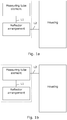
- Figs. 1a and 1b illustrate in block diagram form two different flow meter embodiments.
- a unit which comprises a measuring tube element and a reflector arrangement having at least one reflector and possibly a reflector holder element. These elements are kept in position in relation to each other, at least in one direction, by first locking means L1.
- the first locking means L1 comprises an indentation/protrusion on each element arranged for mutual engagement, such as in the form of a click lock arrangement serving for locking the two elements together, once the first locking means is engaged.
- the reflector arrangement is locked to the housing by means of the second locking means L2 which includes an indentation/protrusion arranged on the reflector and reflector holder, preferably an indentation/protrusion on an outer surface of the reflector or reflector holder which serves to engage with a corresponding protrusion/indentation placed on the inner surface of the through-going opening of the housing into which the reflector arrangement is arranged to be mounted.
- the housing has a protrusion, since this can be directly provided in a moulding process on the inner surface of the through-going opening, whereas an indentation therein required a post moulding process.
- the unit comprising reflector arrangement and measuring tube element is locked to the housing by means of the second locking means L2 which includes an indentation/protrusion arranged on the measuring tube element, preferably on the outer surface of the measuring tube element and which serves to engage with a corresponding protrusion/indentation placed on the inner surface of the through-going opening of the housing into which the unit is arranged to be mounted.
- the second locking means L2 which includes an indentation/protrusion arranged on the measuring tube element, preferably on the outer surface of the measuring tube element and which serves to engage with a corresponding protrusion/indentation placed on the inner surface of the through-going opening of the housing into which the unit is arranged to be mounted.
- each of the first and second locking means L1, L2 may include a set of two or more separate locking means, such as a combination of a pin and hole arrangement for locking relative position in one direction and one or two click lock arrangements for irreversibly locking the two parts together, assisted by the pin and hole arrangement.
- a reversible click lock arrangement is designed for the second locking means L2 such that the locking is not obtained before the desired relative position between the elements has been obtained, and thus the locking serves to maintain this position.
- Figs. 1a and 1b may be combined, such that separate second locking means L2 parts are provided on both of the measuring tube element and the reflector arrangement, thus further serving to lock the measuring tube element and the reflector arrangement to the housing.
- Figs. 2a-2c illustrate different views of a flow meter embodiment with a housing 200 having a generally cylindrical shape and with a generally cylindrically shaped through-going opening 202 forming a pressure-carrying fluid flow passage.
- the two ends of the through-going opening 202 are provided with threads serving for mounting to a piping system.
- the housing 200 in this embodiment is a monolithic polymer structure and has a cavity 206 for housing two ultrasound transducers and measurement circuits for operating the ultrasound transducers.
- the ultrasound transducers transmit/receive ultrasound signal to the flow passage 202 through a polymer wall of the housing 200 and thus operates according to the so-called matching layer principle.
- the cavity 206 is completely sealed from the fluid in the flow passage 202.
- Indentations of the separating wall serve to indicate positions of the transducers and constitute plane surfaces for the transducers when mounted.
- a calculator circuit for determining the consumed amount of fluid based on input from the measurement circuit, and a display for displaying a value representing the consumed amount of fluid may also be placed in the cavity 206 below a transparent lid mounted to the threaded top part of the housing 200.
- a small protrusion 210 is arranged on the inner surface of the through-going opening 202, i.e. inside the flow passage, serving for engagement with the reflector arrangement 220.
- a reflector arrangement 220 is shown in exploded view and mounted in the housing in the partly cut-away view.
- a reflector holder element including two reflector holders 223 monolithically formed together with an intermediate member.
- Two holes 228 on this intermediate member are arranged for mutual engagement with (non-visible) pins on the measuring tube element 222.
- the two holes 228 form part of the first locking means serving to lock the measuring tube element 222 and the reflectors 223 together.
- the remaining part of the first locking means is formed by holes 226 in each side of flexible wings on the intermediate member. These holes 226 serve to engage with corresponding protrusions 227 on each side of the measuring tube element 222.
- the holes 226 are provided on flexible wings, the holes 226 are resiliently arranged in relation to the intermediate member and thus also to the reflector holders 223.
- a click lock or snapping function is provided by engagement with the protrusions 227 on the measuring tube element 222, thus serving to lock the measuring tube element 222 to the reflector holders 223.
- the flexible wings also include holes 225, i.e. second locking means, arranged for mutual engagement with the corresponding protrusions 210 inside the flow passage 202.
- the flexible wing serves to provide a click lock or snapping function between the holes 225 and the protrusions 210 after insertion through one end of the flow passage 202, thus locking the reflector arrangement 220 in position inside the flow passage 202.
- the measuring tube element 222 is in the form of a generally tubular element with a through-going opening for providing the measuring tube.
- the reflectors 224 on the reflector holders 223 are placed outside both ends of the measuring tube element 222, and the reflectors 224 are angled 45° in relation to the fluid flow direction in the measuring tube element 222.
- the reflector surfaces are formed by metal or ceramic reflectors 224, e.g. stainless steel, glued or directly clicked onto the reflector holders 223.
- the metal reflectors 224 could also be mounted during the moulding process of the reflector holders 223, such as moulded into the polymeric part.
- the metal reflectors 224 can in principle be omitted, since the surfaces of the reflector holders 223 can be used as reflectors, provided that the reflector holders 223 are formed in a suitable material serving to provide an acceptable ultrasound reflection.
- the reflector holders 223 as smoothly shaped on the front/back parts such that a minimum disturbance of the fluid flow is created due to the presence of the reflector unit 220 in the flow.
- the reflector holders 223, the intermediate member and the flexible wings with indentations in the form of through-going holes 225, 226 are moulded monolithically to form one single element.
- the single element is moulded using PPS or PES materials, e.g. supplied with a substance serving to increase the ultrasound reflection so as to directly allow ultrasound reflection on the surfaces of the reflector holders 223, thereby making the metal reflectors 224 superfluous.
- the measuring tube element 222 preferably made of polymer, is mounted on the reflector holder arrangement 220 by a snapping mechanism in the form of holes 226 in the reflector holder arrangement serving to engage with corresponding protrusions 227 on the side of the measuring tube element 222.
- Two pin shaped protrusions (not visible) on the measuring tube serve to engage with corresponding holes in the reflector holder arrangement, so as to help to fix the measuring tube element 222 relative to the reflector holder arrangement 220 in the fluid direction.
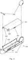
- Fig. 3 illustrates an alternative reflector arrangement 320. Variants mentioned in connection with the reflector arrangement 220 of Figs. 2a-2c apply as well for the one 320 on Fig. 3 .
- reflector holders 323 serve to hold metal reflectors 324, or alternatively the holders 323 may be formed in a material with a sufficient ultrasound reflection making the metal reflectors 324 superfluous.
- the measuring tube is formed by the measuring tube element 321 together with the intermediate structure interconnecting the reflector holders 323, preferably this part of the measuring tube is formed monolithically together with the reflector holders 323.
- the measuring tube element 321 has (non-visible) holes 322 arranged for mutual engagement with protrusions 322 on the reflector holder part. When assembled, the two parts are click locked or snapped together by means of a hole and protrusion arrangement 325.
- indentations 326 serve to lock the reflector arrangement 320 from rotation inside the through-going opening of the housing via engagement with a corresponding protrusion inside the flow passage.
- indentations 327 serve to engage with corresponding protrusions so as to provide a click lock or snapping function which irreversibly locks the reflector arrangement 320 inside the flow passage.
- the measuring tube provided has a non-circular cross section, and in addition the side-line 328 of the inner surface of the measuring tube is seen to be curved, and thus the measuring tube is non-straight but rather has a U-shaped seen in the length direction, and thus the cross section varies along the length direction, having the maximum cross section area in the centre part of the measuring tube, and with minimum cross section areas towards the end parts of the measuring tube.
- locking means can be shaped differently than in the specifically disclosed and described embodiments, such as known by the skilled person.
- different combinations of protrusions and indentations on fixed parts or resiliently mounted parts may serve to provide the desired reversible or irreversible position locking function.
- the invention provides an ultrasound flow meter for measuring a fluid flow rate comprising a housing 200 with a fluid flow passage 202.
- a reflector arrangement 220 comprising one or more reflectors 224 to reflect ultrasound signals.
- First locking means 226, 228 including an indentation or a protrusion is arranged for mutual engagement with corresponding locking means 227 on a separate measuring tube element 222, so as to allow the measuring tube element 222 to be substantially locked in position in relation to the reflector 224 or reflector holder 223.
- Second locking means 225 including an indentation or a protrusion is arranged for mutual engagement with at least one corresponding locking means 210 positioned in the flow passage 202 of the housing 200, so as to allow the reflector arrangement 220 to be substantially locked in position within the flow passage 202 of the housing 200.
- the reflector holder(s) 223 and the first locking means 226, 228, and the second locking means 225 is preferably monolithically formed in a polymeric material and provides click lock or snapping functions with the measuring tube element 222 and with the housing 200.
- a flow meter is provided which requires only few manufacturing steps, since first the measuring tube element 222 is clicked onto the reflector holder 223 element, and next the reflector arrangement 220 thus provided, is clicked into the flow passage 202 of the housing 200.
- the flow meter advantageously forms part of a consumption or utility meter, e.g. a water meter.
Landscapes
- Physics & Mathematics (AREA)
- Fluid Mechanics (AREA)
- General Physics & Mathematics (AREA)
- Electromagnetism (AREA)
- Measuring Volume Flow (AREA)
Priority Applications (2)
| Application Number | Priority Date | Filing Date | Title |
|---|---|---|---|
| PL10156663T PL2278281T3 (pl) | 2009-07-03 | 2010-03-16 | Przepływomierz z jednostką odbłyśnika, blokowaną względem obudowy |
| EP10156663.6A EP2278281B1 (en) | 2009-07-03 | 2010-03-16 | Flow meter with reflector unit locked in relation to housing |
Applications Claiming Priority (3)
| Application Number | Priority Date | Filing Date | Title |
|---|---|---|---|
| EP09164572.1A EP2270439B1 (en) | 2009-07-03 | 2009-07-03 | Flow meter with moulded reflector unit |
| EP09179317A EP2336732A1 (en) | 2009-12-15 | 2009-12-15 | Consumption Meter with Flow Part and Housing Formed by a Monolithic Polymer Structure |
| EP10156663.6A EP2278281B1 (en) | 2009-07-03 | 2010-03-16 | Flow meter with reflector unit locked in relation to housing |
Publications (2)
| Publication Number | Publication Date |
|---|---|
| EP2278281A1 EP2278281A1 (en) | 2011-01-26 |
| EP2278281B1 true EP2278281B1 (en) | 2018-03-07 |
Family
ID=42133627
Family Applications (1)
| Application Number | Title | Priority Date | Filing Date |
|---|---|---|---|
| EP10156663.6A Active EP2278281B1 (en) | 2009-07-03 | 2010-03-16 | Flow meter with reflector unit locked in relation to housing |
Country Status (3)
| Country | Link |
|---|---|
| EP (1) | EP2278281B1 (pl) |
| DK (1) | DK2278281T3 (pl) |
| PL (1) | PL2278281T3 (pl) |
Cited By (2)
| Publication number | Priority date | Publication date | Assignee | Title |
|---|---|---|---|---|
| US11371869B2 (en) | 2019-06-05 | 2022-06-28 | Neptune Technology Group Inc. | Unitized measuring element for water meter assembly |
| IT202200003077A1 (it) * | 2022-02-18 | 2023-08-18 | Pietro Fiorentini Spa | Dispositivo perfezionato per la misura di un fluido, preferibilmente di un gas. |
Families Citing this family (12)
| Publication number | Priority date | Publication date | Assignee | Title |
|---|---|---|---|---|
| EP2423648B9 (en) * | 2010-08-31 | 2016-01-13 | Kamstrup A/S | Ultrasonic flow meter with insert fixed by locking finger |
| DE202012007472U1 (de) * | 2012-08-03 | 2013-11-06 | Hans-Holger Körner | Umlenkspiegelvorrichtung für einen Ultraschalldurchflussmesser und Ultraschalldurchflussmesser |
| DE102013219907A1 (de) * | 2013-10-01 | 2015-04-02 | Landis+Gyr Gmbh | Messeinsatz für einen Durchflussmesser und Verfahren zu dessen Herstellung |
| DE102014019424B4 (de) | 2014-12-20 | 2016-07-21 | Diehl Metering Gmbh | Ultraschallzähler |
| US9714855B2 (en) | 2015-01-26 | 2017-07-25 | Arad Ltd. | Ultrasonic water meter |
| DE102015217024A1 (de) | 2015-09-04 | 2017-03-09 | Landis + Gyr Gmbh | Messarmatur für einen Durchflussmesser |
| WO2017041990A1 (en) * | 2015-09-09 | 2017-03-16 | Danfoss A/S | Two part reflector holder for an ultrasonic flow sensor |
| US10591329B2 (en) | 2016-06-14 | 2020-03-17 | Apator Miitors Aps | Reflector clamping member and use thereof |
| EP3454018B1 (de) * | 2017-09-09 | 2022-06-08 | Diehl Metering GmbH | Durchflusszähler und verfahren zur herstellung eines durchflusszählers |
| DE102017010282B4 (de) | 2017-09-09 | 2022-04-21 | Diehl Metering Gmbh | Durchflusszähler und Verfahren zur Herstellung eines Durchflusszählers |
| US10900819B2 (en) | 2018-08-16 | 2021-01-26 | AXIOMA Metering, UAB | Ultrasonic flowmeter |
| US20220214202A1 (en) * | 2019-05-03 | 2022-07-07 | Kamstrup A/S | Flow tube and housing for a flow meter |
Family Cites Families (5)
| Publication number | Priority date | Publication date | Assignee | Title |
|---|---|---|---|---|
| DK0897102T3 (da) * | 1997-08-14 | 2007-10-29 | Landis & Gyr Gmbh | Ultralyd-gennemströmningsmåler |
| DE10327076B3 (de) * | 2003-06-13 | 2005-04-07 | Hydrometer Gmbh | Ultraschallzähler zur Bestimmung der Durchflussmenge eines strömenden Mediums |
| DE102005063314B4 (de) * | 2005-02-17 | 2010-07-08 | Hydrometer Gmbh | Durchflussmesser |
| PL1983311T3 (pl) | 2007-04-17 | 2021-06-28 | Kamstrup A/S | Miernik zużycia z wbudowanymi komponentami |
| EP2083250A1 (en) | 2007-12-13 | 2009-07-29 | Kamstrup A/S | A polymeric consumption meter with a double layer cover |
-
2010
- 2010-03-16 DK DK10156663.6T patent/DK2278281T3/en active
- 2010-03-16 EP EP10156663.6A patent/EP2278281B1/en active Active
- 2010-03-16 PL PL10156663T patent/PL2278281T3/pl unknown
Non-Patent Citations (1)
| Title |
|---|
| None * |
Cited By (3)
| Publication number | Priority date | Publication date | Assignee | Title |
|---|---|---|---|---|
| US11371869B2 (en) | 2019-06-05 | 2022-06-28 | Neptune Technology Group Inc. | Unitized measuring element for water meter assembly |
| IT202200003077A1 (it) * | 2022-02-18 | 2023-08-18 | Pietro Fiorentini Spa | Dispositivo perfezionato per la misura di un fluido, preferibilmente di un gas. |
| WO2023156963A1 (en) * | 2022-02-18 | 2023-08-24 | Pietro Fiorentini S.P.A. | An improved device for fluid measuring |
Also Published As
| Publication number | Publication date |
|---|---|
| EP2278281A1 (en) | 2011-01-26 |
| PL2278281T3 (pl) | 2018-08-31 |
| DK2278281T3 (en) | 2018-05-28 |
Similar Documents
| Publication | Publication Date | Title |
|---|---|---|
| EP2278281B1 (en) | Flow meter with reflector unit locked in relation to housing | |
| EP3485234B1 (de) | Durchflussmesser mit messkanal | |
| EP3172539B1 (en) | Flow conduit insert for an ultrasonic flowmeter | |
| EP2270439B1 (en) | Flow meter with moulded reflector unit | |
| EP2423648B9 (en) | Ultrasonic flow meter with insert fixed by locking finger | |
| EP2336732A1 (en) | Consumption Meter with Flow Part and Housing Formed by a Monolithic Polymer Structure | |
| DK1967828T3 (en) | A fluid meter | |
| US11614352B2 (en) | Consumption meter with ultrasonic flow measurement | |
| EP0690974A1 (en) | Fluid meter construction | |
| CN112204358A (zh) | 超声波计量装置 | |
| EP2236992A1 (en) | Ultrasonic flow meter capsule | |
| EP2037231A1 (en) | Ultrasonic flow measurement device | |
| WO2010002432A1 (en) | Insertable ultrasonic meter and method | |
| EP2594907A1 (en) | Flow meter with reinforced polymer house | |
| EP3382351B1 (en) | Ultrasonic flow meter | |
| EP3635345B1 (en) | Flow meter with dual flow inserts | |
| EP2659234B1 (en) | Device for measuring the flow rate of a fluid | |
| EP2230490A1 (en) | Positioning of elements in flow meter housings | |
| RU2004110047A (ru) | Вихревой расходомер (варианты) | |
| CN219757419U (zh) | 一种超声波流量计 | |
| CN217953573U (zh) | 一种稳定高效促进剂计量设备 | |
| CN217877839U (zh) | 一种u型反射结构的超声水表 | |
| EP3441727B1 (en) | Insertion ultrasonic sensor assembly | |
| CN210893286U (zh) | 一种可识别液体流向的双向流量计 | |
| CN217083844U (zh) | 超声波流量计 |
Legal Events
| Date | Code | Title | Description |
|---|---|---|---|
| PUAI | Public reference made under article 153(3) epc to a published international application that has entered the european phase |
Free format text: ORIGINAL CODE: 0009012 |
|
| AK | Designated contracting states |
Kind code of ref document: A1 Designated state(s): AT BE BG CH CY CZ DE DK EE ES FI FR GB GR HR HU IE IS IT LI LT LU LV MC MK MT NL NO PL PT RO SE SI SK SM TR |
|
| AX | Request for extension of the european patent |
Extension state: AL BA ME RS |
|
| RIN1 | Information on inventor provided before grant (corrected) |
Inventor name: LAURSEN, PETER SCHMIDT Inventor name: NIELSEN, SOREN TONNES Inventor name: SKALLEBAEK, ANDERS |
|
| 17P | Request for examination filed |
Effective date: 20110706 |
|
| 17Q | First examination report despatched |
Effective date: 20160628 |
|
| GRAP | Despatch of communication of intention to grant a patent |
Free format text: ORIGINAL CODE: EPIDOSNIGR1 |
|
| INTG | Intention to grant announced |
Effective date: 20170919 |
|
| GRAS | Grant fee paid |
Free format text: ORIGINAL CODE: EPIDOSNIGR3 |
|
| GRAA | (expected) grant |
Free format text: ORIGINAL CODE: 0009210 |
|
| AK | Designated contracting states |
Kind code of ref document: B1 Designated state(s): AT BE BG CH CY CZ DE DK EE ES FI FR GB GR HR HU IE IS IT LI LT LU LV MC MK MT NL NO PL PT RO SE SI SK SM TR |
|
| REG | Reference to a national code |
Ref country code: GB Ref legal event code: FG4D |
|
| REG | Reference to a national code |
Ref country code: CH Ref legal event code: EP Ref country code: AT Ref legal event code: REF Ref document number: 977067 Country of ref document: AT Kind code of ref document: T Effective date: 20180315 |
|
| REG | Reference to a national code |
Ref country code: IE Ref legal event code: FG4D |
|
| REG | Reference to a national code |
Ref country code: DE Ref legal event code: R096 Ref document number: 602010048952 Country of ref document: DE |
|
| REG | Reference to a national code |
Ref country code: FR Ref legal event code: PLFP Year of fee payment: 9 |
|
| REG | Reference to a national code |
Ref country code: DK Ref legal event code: T3 Effective date: 20180522 |
|
| REG | Reference to a national code |
Ref country code: NL Ref legal event code: MP Effective date: 20180307 |
|
| REG | Reference to a national code |
Ref country code: LT Ref legal event code: MG4D |
|
| PG25 | Lapsed in a contracting state [announced via postgrant information from national office to epo] |
Ref country code: ES Free format text: LAPSE BECAUSE OF FAILURE TO SUBMIT A TRANSLATION OF THE DESCRIPTION OR TO PAY THE FEE WITHIN THE PRESCRIBED TIME-LIMIT Effective date: 20180307 Ref country code: NO Free format text: LAPSE BECAUSE OF FAILURE TO SUBMIT A TRANSLATION OF THE DESCRIPTION OR TO PAY THE FEE WITHIN THE PRESCRIBED TIME-LIMIT Effective date: 20180607 Ref country code: CY Free format text: LAPSE BECAUSE OF FAILURE TO SUBMIT A TRANSLATION OF THE DESCRIPTION OR TO PAY THE FEE WITHIN THE PRESCRIBED TIME-LIMIT Effective date: 20180307 Ref country code: LT Free format text: LAPSE BECAUSE OF FAILURE TO SUBMIT A TRANSLATION OF THE DESCRIPTION OR TO PAY THE FEE WITHIN THE PRESCRIBED TIME-LIMIT Effective date: 20180307 Ref country code: FI Free format text: LAPSE BECAUSE OF FAILURE TO SUBMIT A TRANSLATION OF THE DESCRIPTION OR TO PAY THE FEE WITHIN THE PRESCRIBED TIME-LIMIT Effective date: 20180307 Ref country code: HR Free format text: LAPSE BECAUSE OF FAILURE TO SUBMIT A TRANSLATION OF THE DESCRIPTION OR TO PAY THE FEE WITHIN THE PRESCRIBED TIME-LIMIT Effective date: 20180307 |
|
| REG | Reference to a national code |
Ref country code: AT Ref legal event code: MK05 Ref document number: 977067 Country of ref document: AT Kind code of ref document: T Effective date: 20180307 |
|
| PG25 | Lapsed in a contracting state [announced via postgrant information from national office to epo] |
Ref country code: BG Free format text: LAPSE BECAUSE OF FAILURE TO SUBMIT A TRANSLATION OF THE DESCRIPTION OR TO PAY THE FEE WITHIN THE PRESCRIBED TIME-LIMIT Effective date: 20180607 Ref country code: SE Free format text: LAPSE BECAUSE OF FAILURE TO SUBMIT A TRANSLATION OF THE DESCRIPTION OR TO PAY THE FEE WITHIN THE PRESCRIBED TIME-LIMIT Effective date: 20180307 Ref country code: LV Free format text: LAPSE BECAUSE OF FAILURE TO SUBMIT A TRANSLATION OF THE DESCRIPTION OR TO PAY THE FEE WITHIN THE PRESCRIBED TIME-LIMIT Effective date: 20180307 Ref country code: GR Free format text: LAPSE BECAUSE OF FAILURE TO SUBMIT A TRANSLATION OF THE DESCRIPTION OR TO PAY THE FEE WITHIN THE PRESCRIBED TIME-LIMIT Effective date: 20180608 |
|
| PG25 | Lapsed in a contracting state [announced via postgrant information from national office to epo] |
Ref country code: RO Free format text: LAPSE BECAUSE OF FAILURE TO SUBMIT A TRANSLATION OF THE DESCRIPTION OR TO PAY THE FEE WITHIN THE PRESCRIBED TIME-LIMIT Effective date: 20180307 Ref country code: IT Free format text: LAPSE BECAUSE OF FAILURE TO SUBMIT A TRANSLATION OF THE DESCRIPTION OR TO PAY THE FEE WITHIN THE PRESCRIBED TIME-LIMIT Effective date: 20180307 Ref country code: EE Free format text: LAPSE BECAUSE OF FAILURE TO SUBMIT A TRANSLATION OF THE DESCRIPTION OR TO PAY THE FEE WITHIN THE PRESCRIBED TIME-LIMIT Effective date: 20180307 Ref country code: NL Free format text: LAPSE BECAUSE OF FAILURE TO SUBMIT A TRANSLATION OF THE DESCRIPTION OR TO PAY THE FEE WITHIN THE PRESCRIBED TIME-LIMIT Effective date: 20180307 |
|
| REG | Reference to a national code |
Ref country code: CH Ref legal event code: PL |
|
| PG25 | Lapsed in a contracting state [announced via postgrant information from national office to epo] |
Ref country code: AT Free format text: LAPSE BECAUSE OF FAILURE TO SUBMIT A TRANSLATION OF THE DESCRIPTION OR TO PAY THE FEE WITHIN THE PRESCRIBED TIME-LIMIT Effective date: 20180307 Ref country code: SM Free format text: LAPSE BECAUSE OF FAILURE TO SUBMIT A TRANSLATION OF THE DESCRIPTION OR TO PAY THE FEE WITHIN THE PRESCRIBED TIME-LIMIT Effective date: 20180307 Ref country code: SK Free format text: LAPSE BECAUSE OF FAILURE TO SUBMIT A TRANSLATION OF THE DESCRIPTION OR TO PAY THE FEE WITHIN THE PRESCRIBED TIME-LIMIT Effective date: 20180307 Ref country code: CZ Free format text: LAPSE BECAUSE OF FAILURE TO SUBMIT A TRANSLATION OF THE DESCRIPTION OR TO PAY THE FEE WITHIN THE PRESCRIBED TIME-LIMIT Effective date: 20180307 |
|
| REG | Reference to a national code |
Ref country code: BE Ref legal event code: MM Effective date: 20180331 Ref country code: DE Ref legal event code: R097 Ref document number: 602010048952 Country of ref document: DE |
|
| REG | Reference to a national code |
Ref country code: IE Ref legal event code: MM4A |
|
| PG25 | Lapsed in a contracting state [announced via postgrant information from national office to epo] |
Ref country code: PT Free format text: LAPSE BECAUSE OF FAILURE TO SUBMIT A TRANSLATION OF THE DESCRIPTION OR TO PAY THE FEE WITHIN THE PRESCRIBED TIME-LIMIT Effective date: 20180709 Ref country code: LU Free format text: LAPSE BECAUSE OF NON-PAYMENT OF DUE FEES Effective date: 20180316 |
|
| PLBE | No opposition filed within time limit |
Free format text: ORIGINAL CODE: 0009261 |
|
| STAA | Information on the status of an ep patent application or granted ep patent |
Free format text: STATUS: NO OPPOSITION FILED WITHIN TIME LIMIT |
|
| PG25 | Lapsed in a contracting state [announced via postgrant information from national office to epo] |
Ref country code: MC Free format text: LAPSE BECAUSE OF FAILURE TO SUBMIT A TRANSLATION OF THE DESCRIPTION OR TO PAY THE FEE WITHIN THE PRESCRIBED TIME-LIMIT Effective date: 20180307 Ref country code: IE Free format text: LAPSE BECAUSE OF NON-PAYMENT OF DUE FEES Effective date: 20180316 |
|
| 26N | No opposition filed |
Effective date: 20181210 |
|
| GBPC | Gb: european patent ceased through non-payment of renewal fee |
Effective date: 20180607 |
|
| PG25 | Lapsed in a contracting state [announced via postgrant information from national office to epo] |
Ref country code: LI Free format text: LAPSE BECAUSE OF NON-PAYMENT OF DUE FEES Effective date: 20180331 Ref country code: SI Free format text: LAPSE BECAUSE OF FAILURE TO SUBMIT A TRANSLATION OF THE DESCRIPTION OR TO PAY THE FEE WITHIN THE PRESCRIBED TIME-LIMIT Effective date: 20180307 Ref country code: CH Free format text: LAPSE BECAUSE OF NON-PAYMENT OF DUE FEES Effective date: 20180331 Ref country code: BE Free format text: LAPSE BECAUSE OF NON-PAYMENT OF DUE FEES Effective date: 20180331 |
|
| PG25 | Lapsed in a contracting state [announced via postgrant information from national office to epo] |
Ref country code: GB Free format text: LAPSE BECAUSE OF NON-PAYMENT OF DUE FEES Effective date: 20180607 |
|
| PG25 | Lapsed in a contracting state [announced via postgrant information from national office to epo] |
Ref country code: MT Free format text: LAPSE BECAUSE OF NON-PAYMENT OF DUE FEES Effective date: 20180316 |
|
| PG25 | Lapsed in a contracting state [announced via postgrant information from national office to epo] |
Ref country code: TR Free format text: LAPSE BECAUSE OF FAILURE TO SUBMIT A TRANSLATION OF THE DESCRIPTION OR TO PAY THE FEE WITHIN THE PRESCRIBED TIME-LIMIT Effective date: 20180307 |
|
| PG25 | Lapsed in a contracting state [announced via postgrant information from national office to epo] |
Ref country code: HU Free format text: LAPSE BECAUSE OF FAILURE TO SUBMIT A TRANSLATION OF THE DESCRIPTION OR TO PAY THE FEE WITHIN THE PRESCRIBED TIME-LIMIT; INVALID AB INITIO Effective date: 20100316 |
|
| PG25 | Lapsed in a contracting state [announced via postgrant information from national office to epo] |
Ref country code: MK Free format text: LAPSE BECAUSE OF NON-PAYMENT OF DUE FEES Effective date: 20180307 |
|
| PG25 | Lapsed in a contracting state [announced via postgrant information from national office to epo] |
Ref country code: IS Free format text: LAPSE BECAUSE OF FAILURE TO SUBMIT A TRANSLATION OF THE DESCRIPTION OR TO PAY THE FEE WITHIN THE PRESCRIBED TIME-LIMIT Effective date: 20180707 |
|
| PGFP | Annual fee paid to national office [announced via postgrant information from national office to epo] |
Ref country code: FR Payment date: 20230322 Year of fee payment: 14 Ref country code: DK Payment date: 20230323 Year of fee payment: 14 |
|
| PGFP | Annual fee paid to national office [announced via postgrant information from national office to epo] |
Ref country code: PL Payment date: 20230303 Year of fee payment: 14 |
|
| P01 | Opt-out of the competence of the unified patent court (upc) registered |
Effective date: 20230517 |
|
| PGFP | Annual fee paid to national office [announced via postgrant information from national office to epo] |
Ref country code: DE Payment date: 20240320 Year of fee payment: 15 |