EP2278232A2 - Hot humidifier - Google Patents
Hot humidifier Download PDFInfo
- Publication number
- EP2278232A2 EP2278232A2 EP10164353A EP10164353A EP2278232A2 EP 2278232 A2 EP2278232 A2 EP 2278232A2 EP 10164353 A EP10164353 A EP 10164353A EP 10164353 A EP10164353 A EP 10164353A EP 2278232 A2 EP2278232 A2 EP 2278232A2
- Authority
- EP
- European Patent Office
- Prior art keywords
- tank
- boiler
- humidifier
- water
- hot
- Prior art date
- Legal status (The legal status is an assumption and is not a legal conclusion. Google has not performed a legal analysis and makes no representation as to the accuracy of the status listed.)
- Withdrawn
Links
Images


Classifications
-
- F—MECHANICAL ENGINEERING; LIGHTING; HEATING; WEAPONS; BLASTING
- F24—HEATING; RANGES; VENTILATING
- F24F—AIR-CONDITIONING; AIR-HUMIDIFICATION; VENTILATION; USE OF AIR CURRENTS FOR SCREENING
- F24F6/00—Air-humidification, e.g. cooling by humidification
- F24F6/18—Air-humidification, e.g. cooling by humidification by injection of steam into the air
Definitions
- the present invention relates to a hot humidifier, i.e. a device for generating steam by heating water.
- steam is generally produced by using electrically powered armoured resistance elements. These resistance elements are immersed in water contained in a so-called boiler, i.e. a vessel forming part of the humidifier and communicating upperly with the environment.
- the humidifier also comprises a water tank connected to the boiler via a small channel. The tank is provided with an upper aperture for water top-up
- the tank and water heater are two separate units which are spaced apart to reduce heat transmission from the water heater to the tank as much as possible.
- the humidifier must be able to operate continuously even for several hours, hence the water in the tank could boil away if the said heat transmission is not reduced to the greatest possible extent.
- the object of the present invention is to provide a humidifier which, although the water in the tank does not attain a dangerous temperature, is of smaller bulk than known humidifiers.
- a hot humidifier according to the present invention in which the tank is spaced from the boiler such that the temperature of the water in the tank does not attain dangerous values for the user, characterised in that the tank surrounds the boiler.
- the hot humidifier 10 comprises a roughly frustoconical boiler 12 tapering upwards to form a circular (when seen in plan) upper aperture closable by a cap or cover 14 provided with an aperture 15 through which steam can leave, this being produced in the boiler 12 by conventional armoured electrical resistance elements (not shown for simplicity) provided in its lower part to heat the water present in the boiler 12.
- the free surface of the water present in the boiler 12 must not be less than a predetermined minimum level (in practice it must not fall such as to uncover the armoured resistance elements).
- the humidifier 10 also comprises a water tank, indicated overall by 18.
- the boiler 12 and the tank 18 communicate via a short conduit 16 such that, by the principle of communicating vessels, the water level in the boiler 12 is the same as in the tank 18.
- This latter laterally surrounds the boiler 12, which is itself surrounded laterally by an interspace 20 open upperly such as to communicate with the environment.
- the presence of the interspace 20 enables heat transmission between the boiler 12 and tank 18 to be drastically reduced, so preventing the water temperature in the tank 18 from reaching values which could be dangerous for the user.
- the fact of having shaped the water tank such that it laterally surrounds the boiler 12 enables a hot humidifier to be obtained having small dimensions, making it much less bulky than known hot humidifiers.
- the free surface of the water in the tank 18 gradually falls due to steam formation.
- a warning means sound and/or light, not visible in the figures
- the tank 18 is topped up through an upper aperture 22.
- that part of the external casing of the humidifier 10 which surrounds the aperture 22 is funnel shaped to facilitate operation.
- the hot humidifier shown in Figures 3 and 4 is of circular shape in plan view. It is provided with an upperly open boiler 32, again of roughly frustoconical shape, in the lower part of which two armoured resistance elements 31 are provided to heat the water. Again in this case the boiler 32 is completely surrounded laterally by an interspace 40 closed upperly by a cover 34 provided with apertures, indicated by 35 in Figure 3 , which enable the steam formed in the boiler 32 to escape into the atmosphere.
- the external and internal lateral walls of the tank 38 form a single piece, indicated overall by 33, essentially shaped as a ring, with the boiler located at the ring centre.
- the tank 38 does not communicate with the outside when the piece 33 is mounted, communicating instead with the lower part of the boiler 32 via a valve 37 ( Figure 3 ) and an aperture 36 (better seen in Figure 4 ) through which the water can flow in the direction of the arrow W.
- the valve 37 is open when the piece 33 is mounted (for example by screwing), whereas it closes automatically when the piece 33 is removed from the remaining part (indicated overall by 42 in Figure 3 ) of the humidifier 30, to provide for filling the tank 38.
- the piece 33 once demounted, is inverted and the part 39 (which in this case can be unscrewed), acting as the cover, is removed to be able to introduce water.
- the cover 39 is again screwed on and the piece 33 is finally remounted onto the remaining part 42 of the humidifier 30, to again attain the situation of Figure 3 .
- the tank 38 (not being in communication with the outside) goes under negative pressure, this enabling the level of the free water surface to remain unvaried in the boiler 32.
- the humidifier 32 can also be provided with warning means (sound and/or light), also not shown for simplicity, which are activated when the free surface of the water in the tank falls below a determined level, with simultaneous deactivation of the armoured resistance elements 41 positioned in the boiler 32.
- warning means sound and/or light
- the present invention makes it possible to provide hot humidifiers of decidedly smaller dimensions than in the case of known humidifiers of this type.
Landscapes
- Engineering & Computer Science (AREA)
- Chemical & Material Sciences (AREA)
- Combustion & Propulsion (AREA)
- Mechanical Engineering (AREA)
- General Engineering & Computer Science (AREA)
- Air Humidification (AREA)
Abstract
Description
- The present invention relates to a hot humidifier, i.e. a device for generating steam by heating water.
- In known hot humidifiers, steam is generally produced by using electrically powered armoured resistance elements. These resistance elements are immersed in water contained in a so-called boiler, i.e. a vessel forming part of the humidifier and communicating upperly with the environment. The humidifier also comprises a water tank connected to the boiler via a small channel. The tank is provided with an upper aperture for water top-up
In known humidifiers the tank and water heater are two separate units which are spaced apart to reduce heat transmission from the water heater to the tank as much as possible. In this respect it should also be noted that the humidifier must be able to operate continuously even for several hours, hence the water in the tank could boil away if the said heat transmission is not reduced to the greatest possible extent. - As the tank must be accessible to the user for top-up, a high water temperature could represent a danger.
- The fact of sufficiently spacing the tank from the boiler means that thermal energy is transferred from the boiler to the tank essentially only through said small channel connecting the two together, this being insufficient to enable the tank water to reach a dangerous temperature. This solution has however the drawback of forming rather bulky humidifiers.
- The object of the present invention is to provide a humidifier which, although the water in the tank does not attain a dangerous temperature, is of smaller bulk than known humidifiers.
- This object is attained by a hot humidifier according to the present invention, in which the tank is spaced from the boiler such that the temperature of the water in the tank does not attain dangerous values for the user, characterised in that the tank surrounds the boiler.
- The invention will be more apparent from the ensuing description of two embodiments thereof. In this description reference is made to the accompanying drawings, in which:
-
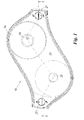
Figure 1 is a plan view of a first humidifier according to the present invention; -
Figure 2 is a vertical section therethrough on the line 2-2 ofFigure 1 ; -
Figure 3 is a coaxial vertical section through a second embodiment of a humidifier according to the present invention, roughly of egg shape externally; -
Figure 4 is an enlarged detail 4 ofFigure 3 . - As can be seen from
Figures 1 and2 , thehot humidifier 10 comprises a roughlyfrustoconical boiler 12 tapering upwards to form a circular (when seen in plan) upper aperture closable by a cap orcover 14 provided with anaperture 15 through which steam can leave, this being produced in theboiler 12 by conventional armoured electrical resistance elements (not shown for simplicity) provided in its lower part to heat the water present in theboiler 12. The free surface of the water present in theboiler 12 must not be less than a predetermined minimum level (in practice it must not fall such as to uncover the armoured resistance elements). Thehumidifier 10 also comprises a water tank, indicated overall by 18. Theboiler 12 and thetank 18 communicate via ashort conduit 16 such that, by the principle of communicating vessels, the water level in theboiler 12 is the same as in thetank 18. This latter laterally surrounds theboiler 12, which is itself surrounded laterally by aninterspace 20 open upperly such as to communicate with the environment. The presence of theinterspace 20 enables heat transmission between theboiler 12 andtank 18 to be drastically reduced, so preventing the water temperature in thetank 18 from reaching values which could be dangerous for the user. However, the fact of having shaped the water tank such that it laterally surrounds theboiler 12 enables a hot humidifier to be obtained having small dimensions, making it much less bulky than known hot humidifiers. - When the
humidifier 10 is in operation, the free surface of the water in thetank 18 gradually falls due to steam formation. When a predetermined minimum level is reached, a warning means (sound and/or light, not visible in the figures) which warns of the need to add water to thetank 18, while at the same time the electrical power to the armoured resistance elements is interrupted. Thetank 18 is topped up through anupper aperture 22. As can be seen fromFigures 1 and2 , that part of the external casing of thehumidifier 10 which surrounds theaperture 22 is funnel shaped to facilitate operation. - As is apparent from
Figure 2 in particular, the top of thehumidifier 10 casing and that part of this casing which forms theinterspace 20 form a single removable piece, indicated overall by 23, held in position by conventional knob means 27 (of which only one is shown inFigure 2 ). - The hot humidifier shown in
Figures 3 and 4 , and indicated overall by 30, is of circular shape in plan view. It is provided with an upperlyopen boiler 32, again of roughly frustoconical shape, in the lower part of which twoarmoured resistance elements 31 are provided to heat the water. Again in this case theboiler 32 is completely surrounded laterally by an interspace 40 closed upperly by acover 34 provided with apertures, indicated by 35 inFigure 3 , which enable the steam formed in theboiler 32 to escape into the atmosphere. The external and internal lateral walls of thetank 38 form a single piece, indicated overall by 33, essentially shaped as a ring, with the boiler located at the ring centre. However, in contrast to thetank 18 of thehumidifier 10, thetank 38 does not communicate with the outside when thepiece 33 is mounted, communicating instead with the lower part of theboiler 32 via a valve 37 (Figure 3 ) and an aperture 36 (better seen inFigure 4 ) through which the water can flow in the direction of the arrow W. Thevalve 37 is open when thepiece 33 is mounted (for example by screwing), whereas it closes automatically when thepiece 33 is removed from the remaining part (indicated overall by 42 inFigure 3 ) of thehumidifier 30, to provide for filling thetank 38. For this purpose thepiece 33, once demounted, is inverted and the part 39 (which in this case can be unscrewed), acting as the cover, is removed to be able to introduce water. Thecover 39 is again screwed on and thepiece 33 is finally remounted onto theremaining part 42 of thehumidifier 30, to again attain the situation ofFigure 3 . - It should be noted that following water evaporation in the
boiler 32, the tank 38 (not being in communication with the outside) goes under negative pressure, this enabling the level of the free water surface to remain unvaried in theboiler 32. - As in the case of the
humidifier 10, thehumidifier 32 can also be provided with warning means (sound and/or light), also not shown for simplicity, which are activated when the free surface of the water in the tank falls below a determined level, with simultaneous deactivation of the armoured resistance elements 41 positioned in theboiler 32. - As will be apparent from the aforegoing, the present invention makes it possible to provide hot humidifiers of decidedly smaller dimensions than in the case of known humidifiers of this type.
Claims (7)
- A hot humidifier (10; 30) comprising a boiler (12; 32) in communication with the environment, and a water tank (18;38) communicating with the boiler (12; 32) such that the water covers a heating means (41) of electrical resistance type contained in the boiler (12; 32) to produce steam, the tank (18; 38) and the boiler (12; 32) being spaced apart such that the temperature of the water in the tank (18; 38) does not attain dangerous values for the user, characterised in that the tank (18; 32) surrounds the boiler (12; 32).
- A hot humidifier (10; 30) as claimed in claim 1, wherein the tank (18; 38) surrounds the boiler (12; 32) only laterally.
- A hot humidifier (10) as claimed in claim 1, wherein the tank (18) communicates with the environment via an upper aperture (22).
- A hot humidifier (10) as claimed in claim 3, wherein that external casing part which surrounds the upper aperture (22) is of funnel shape.
- A hot humidifier (30) as claimed in claim 1, wherein the interior of the tank (38) is isolated from the environment when the humidifier (30) is in operation, so that the tank (38) goes under negative pressure during operation of the humidifier (30).
- A hot humidifier (30) as claimed in claim 5, wherein the tank (38) is shaped as a ring with the boiler (32) positioned centrally.
- A hot humidifier (30) as claimed in claim 5, wherein the tank (38) is separable from the remaining part (42) of the humidifier (30), communication between the tank (38) and boiler (32) taking place via a valve (37) which is open when the tank (38) is mounted, whereas it is closed when the tank (38) is removed.
Applications Claiming Priority (1)
| Application Number | Priority Date | Filing Date | Title |
|---|---|---|---|
| ITMI20090207 ITMI20090207U1 (en) | 2009-06-18 | 2009-06-18 | "HUMIDIFIER HOT" |
Publications (2)
| Publication Number | Publication Date |
|---|---|
| EP2278232A2 true EP2278232A2 (en) | 2011-01-26 |
| EP2278232A3 EP2278232A3 (en) | 2014-10-01 |
Family
ID=42732058
Family Applications (1)
| Application Number | Title | Priority Date | Filing Date |
|---|---|---|---|
| EP10164353.4A Withdrawn EP2278232A3 (en) | 2009-06-18 | 2010-05-28 | Hot humidifier |
Country Status (2)
| Country | Link |
|---|---|
| EP (1) | EP2278232A3 (en) |
| IT (1) | ITMI20090207U1 (en) |
Cited By (3)
| Publication number | Priority date | Publication date | Assignee | Title |
|---|---|---|---|---|
| GB2484076A (en) * | 2010-09-28 | 2012-04-04 | Amanda Hayes | Humidifier |
| ITVR20130173A1 (en) * | 2013-07-23 | 2015-01-24 | Elettroplastica S P A | HOT HUMIDIFIER |
| EP3561403A4 (en) * | 2016-12-21 | 2020-07-22 | Gree Electric Appliances, Inc. of Zhuhai | Anti-splash structure and humidification apparatus |
Family Cites Families (8)
| Publication number | Priority date | Publication date | Assignee | Title |
|---|---|---|---|---|
| US2213851A (en) * | 1939-01-05 | 1940-09-03 | Metalectric Corp | Humidifier |
| US2763765A (en) * | 1954-12-03 | 1956-09-18 | American Sundries Co | Vaporizers |
| US4028526A (en) * | 1969-06-11 | 1977-06-07 | Schossow George W | Electrically grounded vaporizer structure |
| US4132883A (en) * | 1976-06-14 | 1979-01-02 | Champion Spark Plug Company | Electric steam vaporizer |
| CA2296154A1 (en) * | 2000-01-17 | 2001-07-17 | Paul Crowhurst | Portable humidifier |
| US6560408B2 (en) * | 2001-04-20 | 2003-05-06 | Appliance Development Corporation | Humidifier |
| EP1777467A1 (en) * | 2005-10-19 | 2007-04-25 | De' Longhi S.P.A. | Vaporisation apparatus for an environment |
| KR100745593B1 (en) * | 2006-03-06 | 2007-08-03 | 삼성광주전자 주식회사 | A steam generating apparatus |
-
2009
- 2009-06-18 IT ITMI20090207 patent/ITMI20090207U1/en unknown
-
2010
- 2010-05-28 EP EP10164353.4A patent/EP2278232A3/en not_active Withdrawn
Non-Patent Citations (1)
| Title |
|---|
| None |
Cited By (3)
| Publication number | Priority date | Publication date | Assignee | Title |
|---|---|---|---|---|
| GB2484076A (en) * | 2010-09-28 | 2012-04-04 | Amanda Hayes | Humidifier |
| ITVR20130173A1 (en) * | 2013-07-23 | 2015-01-24 | Elettroplastica S P A | HOT HUMIDIFIER |
| EP3561403A4 (en) * | 2016-12-21 | 2020-07-22 | Gree Electric Appliances, Inc. of Zhuhai | Anti-splash structure and humidification apparatus |
Also Published As
| Publication number | Publication date |
|---|---|
| EP2278232A3 (en) | 2014-10-01 |
| ITMI20090207U1 (en) | 2010-12-19 |
Similar Documents
| Publication | Publication Date | Title |
|---|---|---|
| US11627825B2 (en) | Modular steamer accessory for steam-heating and/or steam-cooking food contained in a container | |
| US11523701B2 (en) | Accessory for steam-heating and/or steam-cooking food and steamer comprising a container and an accessory for steam-heating and/or steam-cooking food contained in the container | |
| JP6473245B2 (en) | Steam cooker attachment apparatus for steam heating and / or cooking food contained in a container | |
| EP2278232A2 (en) | Hot humidifier | |
| KR20050091879A (en) | Cooking device | |
| CN211242957U (en) | Air fryer with good use experience | |
| JP2020501745A (en) | Improved steamer accessory for steam heating and / or steam cooking food in a container | |
| JP2015009149A (en) | Ecological cooking appliance | |
| CN212912906U (en) | Use and experience good steam and fry pot | |
| CN201920490U (en) | Water storage type kettle | |
| KR101222567B1 (en) | heating apparatus using water vapour bubble and method of using the same | |
| US1393762A (en) | Cooking apparatus | |
| KR101224626B1 (en) | The double boiler where the automatic water level control is possible | |
| CN203555522U (en) | Electric rice cooker | |
| CN207827034U (en) | A kind of fluid storage tanks | |
| KR20120109454A (en) | Heating apparatus using water vapour bubble and method of using the same | |
| CN205913238U (en) | Steam cooking stove | |
| CN203555117U (en) | Steam heating cooker | |
| KR20190100034A (en) | Cap for water supply and steam generator using the same | |
| KR101949637B1 (en) | Cap for water supply and steam generator using the same | |
| CN216393794U (en) | Cooking utensil | |
| CN219699631U (en) | Novel kettle | |
| RU50740U1 (en) | CONTINUOUS ELECTRIC CENTER | |
| US1344161A (en) | Apparatus for preparing coffee infusion | |
| KR200157755Y1 (en) | Instrument for indicating the pressure in an electric pressure rice cooker |
Legal Events
| Date | Code | Title | Description |
|---|---|---|---|
| PUAI | Public reference made under article 153(3) epc to a published international application that has entered the european phase |
Free format text: ORIGINAL CODE: 0009012 |
|
| AK | Designated contracting states |
Kind code of ref document: A2 Designated state(s): AL AT BE BG CH CY CZ DE DK EE ES FI FR GB GR HR HU IE IS IT LI LT LU LV MC MK MT NL NO PL PT RO SE SI SK SM TR |
|
| AX | Request for extension of the european patent |
Extension state: BA ME RS |
|
| PUAL | Search report despatched |
Free format text: ORIGINAL CODE: 0009013 |
|
| AK | Designated contracting states |
Kind code of ref document: A3 Designated state(s): AL AT BE BG CH CY CZ DE DK EE ES FI FR GB GR HR HU IE IS IT LI LT LU LV MC MK MT NL NO PL PT RO SE SI SK SM TR |
|
| AX | Request for extension of the european patent |
Extension state: BA ME RS |
|
| RIC1 | Information provided on ipc code assigned before grant |
Ipc: F24F 6/18 20060101AFI20140825BHEP |
|
| STAA | Information on the status of an ep patent application or granted ep patent |
Free format text: STATUS: THE APPLICATION IS DEEMED TO BE WITHDRAWN |
|
| 18D | Application deemed to be withdrawn |
Effective date: 20150402 |