EP2278184A1 - Adjustable damper device - Google Patents
Adjustable damper device Download PDFInfo
- Publication number
- EP2278184A1 EP2278184A1 EP10007433A EP10007433A EP2278184A1 EP 2278184 A1 EP2278184 A1 EP 2278184A1 EP 10007433 A EP10007433 A EP 10007433A EP 10007433 A EP10007433 A EP 10007433A EP 2278184 A1 EP2278184 A1 EP 2278184A1
- Authority
- EP
- European Patent Office
- Prior art keywords
- lamella
- sliding
- rotor
- bundle
- rotary
- Prior art date
- Legal status (The legal status is an assumption and is not a legal conclusion. Google has not performed a legal analysis and makes no representation as to the accuracy of the status listed.)
- Granted
Links
Images



Classifications
-
- F—MECHANICAL ENGINEERING; LIGHTING; HEATING; WEAPONS; BLASTING
- F16—ENGINEERING ELEMENTS AND UNITS; GENERAL MEASURES FOR PRODUCING AND MAINTAINING EFFECTIVE FUNCTIONING OF MACHINES OR INSTALLATIONS; THERMAL INSULATION IN GENERAL
- F16F—SPRINGS; SHOCK-ABSORBERS; MEANS FOR DAMPING VIBRATION
- F16F9/00—Springs, vibration-dampers, shock-absorbers, or similarly-constructed movement-dampers using a fluid or the equivalent as damping medium
- F16F9/10—Springs, vibration-dampers, shock-absorbers, or similarly-constructed movement-dampers using a fluid or the equivalent as damping medium using liquid only; using a fluid of which the nature is immaterial
- F16F9/12—Devices with one or more rotary vanes turning in the fluid any throttling effect being immaterial, i.e. damping by viscous shear effect only
- F16F9/125—Devices with one or more rotary vanes turning in the fluid any throttling effect being immaterial, i.e. damping by viscous shear effect only characterised by adjustment means
Definitions
- the invention relates to an adjustable damper device comprising:
- Such a damper device is known in the art from Japanese patent application 63067437 .
- the amount of viscous drag is proportional to the surface area and the clearance of the adjacent lamellas, which are facing each other.
- a lamella is a flat object or a part thereof, often having an elongated shape but a lamella may also be a circular flat disk or another flat object having a different shape, whether or not provided with openings or slits.
- dampers are also often applied for damping the motion of an opening or closing door or sliding door.
- This type of damper device is also used as a damper on the drive chains of fences, gates or garage doors.
- the known damper device has the disadvantage that the degree of damping can not be easily adapted to the application, the need and/or the dynamics, forces and weights of the system to be dampened, such as a fence or garage, so for each dampening rate a separate damper device must be produced. Because of the cylindrical shape of the housing, and the symmetrical arrangement of the rotor within the housing the range of adjustment is too small. Therefore two bundles of adjustable lamellas each with an adjustment device are needed, making the damper device complicated and costly to manufacture.
- Object of the invention is, therefore, to provide for an adjustable damper device without any such aforementioned disadvantages.
- a further object is to provide for a damper device that
- a broad dampening range is obtained by making the sliding lamella displaceable between a substantially overlapping position nearby or around the rotor and a basically radially displaced position within the interior space of the housing, having little or no overlap. Furthermore a relatively flat box type of housing is herewith possible having a low axial height. Moreover this damper device comprises less complicated parts and may be manufactured at lower costs.
- the surface areas of the lamellas of the first and the second lamella bundle In axial direction have maximum overlap.
- the sliding lamella is provided with a recess having a size corresponding to the diameter of the rotor, so that the sliding lamella is configured to be displaceable past the rotor.
- a broad dampening range is obtained for the damper device, by making is possible for the sliding lamellas to completely overlap the rotary lamellas.
- the recesses in the sliding lamellas is it possible for the sliding lamella to completely overlap both sides of the rotary lamellas with respect to the rotor.
- a special embodiment is characterized in that the sliding lamella is radially adjustable relative to the rotor or the sliding lamella is tiltable towards and from the rotor.
- the large (radial) adjustability of the sliding lamellas allows for a compact construction while maintaining a broad range of damping. By tilting the lamella to and from the rotor, the same broad range of dampening strength and radial adjustability is achieved.
- the first lamella bundle is configured by two or more rotary lamellas which are axially parallelly mounted upon the rotor having a rotary lamella clearance distance such that the sliding lamellas of the second lamella bundle may be introduced into the rotary lamella clearance.
- the shear or viscous forces between the dampening liquid and the rotary lamellas is increased by creating two damping clearances in each rotary lamella clearance by interposing a sliding lamella between two rotary lamellas, Furthermore increasing the overlap between the rotary lamellas and the sliding lamella increases the surface area of each clearance and therewith the dampening strength.
- the sliding lamella is formed by two or more sliding lamella segments; preferably the sliding lamella segments are circle segments, which form circular disks in the damping position.
- the second lamella bundle is provided with a connection element, like a connection plate, where upon the sliding lamellas are essentially parallelly mounted having a sliding lamella clearance.
- a connection element like a connection plate
- the lamella bundle can be adjusted as one piece and may be easily completely inserted into the rotary lamella bundle for maximum damping. It is also possible, however, to adjust the single lamellas independently.
- the adjustment device is an adjusting axis, which extends outside the housing, by which the second lamella bundle may be radially adjusted, with respect to the rotor.
- the adjusting axis and the connection plate of the second lamella bundle are provided with cooperating threading such that by rotating the adjustment axis the second lamella bundle is radially displaced with respect to the rotor within the interior space of the housing.
- the adjusting device and the connecting plate of the second lamella bundle can alternatively be provided with a pushing/pulling mechanism without a thread.
- This simple and easy to manufacture adjustment axis renders, for example by means of threads, the sliding lamella easily adjustable, with little chance of leakage of the dampening fluid.
- the rotor with the first lamella bundle is mounted adjacently to the side wall of the interior space of the housing and the second lamella bundle with the connection element is mounted adjacently to the opposite side wall.
- the first lamella bundle is formed by circular rotary lamellas and the adjacent side wall is conformingly concavely circularly shaped and the sliding lamellas of the second lamella bundle at their outer ends are also provided with a conformingly circular shape.
- the connection element may also be concavely shaped, so that in the damping position of the damping device according to the invention, the arrangement of rotor and lamellas is conforming to a traditional damper having a cylindrically shaped housing or stator.
- Fig.1A shows in cross-section in side view the adjustable damper device 1 according to the invention having housing 3 and a rotary shaft or rotor 4, extending out of the housing.
- This rotor may be connected to an object to be dampened, like a door, with a gear-wheel or sprocket so that the rotation - or a linear movement converted into a rotary movement - may be dampened.
- the interior space 2 (see Fig.1B ) is provided with a dampening liquid like silicon oil.
- the rotor 4 within the interior space 2 of the housing 3 is provided with an axel stub or shaft bearing, alternatively this rotor may also be passed through the opposite wall or through both walls.
- Rotor 4 is provided with a lamella bundle 5, which comprises at least one rotary lamella 6.
- rotary lamella 6 is a flat object or small plate having a constant diameter or thickness, but may also be provided with an alternative different shape.
- the first lamella bundle 5 comprises six rotary lamellas, extending radially with respect to the rotor 4 and axially being fixedly interconnected at a regular mutual distance or clearance with rotor 4.
- the adjusting device 10 is an adjustment axis by which the whole second lamella bundle 7 may be displaced in the direction of the rotor 4.
- rotary lamellas 6 are provided with a mutual clearance 11, whereby the clearance is provided with such a dimension, that the sliding lamellas 8 may be inserted or interposed between two rotary lamellas.
- Fig.1B is shown in cross-section in top view the adjustable damper 1 of Fig.1A having a disk-shaped rotary lamella 6 and a sliding lamella 8 in the extreme free position having the lowest dampening strength.
- the adjustment axis 10 is connected with sliding lamella 8 in such a way, that at the outside of the housing the sliding lamella 8 may be displaced or shifted in the direction of the rotor 4.
- the adjustable damper device 1 of Fig. 1A - 1B is shown with second lamella bundle 7 in its extreme damping position.
- the sliding lamellas 8 substantially, for a major part, overlap the rotary lamellas 5. Therefore the sliding lamellas are provided with recess 9 having a dimension, which corresponds with the diameter of the rotor 4, so that parts of the sliding lamella extend past the rotor 4.
- the lamellas of the second lamella bundle 7 are connected by means of a connection element 14; in the embodiment shown the connection element is a connection plate 14, which is provided at the backside of the second lamella bundle 7, thereby mutually parallely connecting the sliding lamellas.
- the sliding lamellas 8 are mutually parallely mounted onto connection element 14 configuring a mutual clearance distance 11'.
- This clearance distance corresponds preferably with the dimensions of clearance 11 of the first lamella bundle 5 so that the lamella bundles may easily be stacked, interposed or be slid together.
Landscapes
- Engineering & Computer Science (AREA)
- General Engineering & Computer Science (AREA)
- Mechanical Engineering (AREA)
- Fluid-Damping Devices (AREA)
- Vibration Dampers (AREA)
Abstract
the internal space (2) being provided with: a first lamella bundle (5) comprising at least one rotary lamella (6) being connected with the rotor (4),
a second lamella bundle (7) comprising at least one sliding lamella (8) being connected with the housing (2); an adjustment device (10) for radially displacing the second lamella bundle (7) relatively to the rotor (4); wherein the second lamella bundle (7) is adjustable between:
a damping position whereby a substantial portion of the surface area of the sliding lamella (8) is axially positioned adjacently to the surface area of the rotary lamella (6), and
a free position whereby a substantial portion of the surface area of the sliding lamella (8) is axially positioned distantly to the surface area of the rotary lamella.
Description
- The invention relates to an adjustable damper device comprising:
- a housing provided with an internal space for receiving a dampening fluid;
- a rotor extending into the internal space of the housing and being disposed rotatably within the housing;
- the internal space being provided with:
- a first lamella bundle comprising at least one rotary lamella being connected with the rotor and essentially radially extending relatively to the rotor and being rotatable relatively to the housing,
- a second lamella bundle comprising at least one sliding lamella being connected with the housing and essentially extending parallely to the rotary lamella,
- an adjustment device for radially displacing the second lamella bundle relatively to the rotor.
- Such a damper device is known in the art from Japanese patent application
63067437 - A lamella is a flat object or a part thereof, often having an elongated shape but a lamella may also be a circular flat disk or another flat object having a different shape, whether or not provided with openings or slits.
- Such dampers are also often applied for damping the motion of an opening or closing door or sliding door. This type of damper device is also used as a damper on the drive chains of fences, gates or garage doors. The known damper device has the disadvantage that the degree of damping can not be easily adapted to the application, the need and/or the dynamics, forces and weights of the system to be dampened, such as a fence or garage, so for each dampening rate a separate damper device must be produced. Because of the cylindrical shape of the housing, and the symmetrical arrangement of the rotor within the housing the range of adjustment is too small. Therefore two bundles of adjustable lamellas each with an adjustment device are needed, making the damper device complicated and costly to manufacture.
- There is also a need for a damper device which combines a wide range of dampening settings with a low axial height.
- Object of the invention is, therefore, to provide for an adjustable damper device without any such aforementioned disadvantages.
- A further object is to provide for a damper device that
- is simple and may be manufactured at low cost,
- is easily adjustable and is having a large dampening range,
- is having a low axial height.
- Objects of the invention are achieved with an the second lamella bundle being adjustable between:
- a damping position whereby a substantial portion of the surface area of the sliding lamella is axially positioned adjacently with respect to the surface area of the rotary lamella, and
- a free position whereby a substantial portion of the surface of the sliding lamella is radially positioned distantly with respect to the surface area of the rotary lamella.
- A broad dampening range is obtained by making the sliding lamella displaceable between a substantially overlapping position nearby or around the rotor and a basically radially displaced position within the interior space of the housing, having little or no overlap. Furthermore a relatively flat box type of housing is herewith possible having a low axial height. Moreover this damper device comprises less complicated parts and may be manufactured at lower costs.
- In an advantageous embodiment in the damping position the surface areas of the lamellas of the first and the second lamella bundle In axial direction have maximum overlap.
Preferably the sliding lamella is provided with a recess having a size corresponding to the diameter of the rotor, so that the sliding lamella is configured to be displaceable past the rotor.
A broad dampening range is obtained for the damper device, by making is possible for the sliding lamellas to completely overlap the rotary lamellas. By means of the recesses in the sliding lamellas is it possible for the sliding lamella to completely overlap both sides of the rotary lamellas with respect to the rotor. - A special embodiment is characterized in that the sliding lamella is radially adjustable relative to the rotor or the sliding lamella is tiltable towards and from the rotor.
The large (radial) adjustability of the sliding lamellas allows for a compact construction while maintaining a broad range of damping. By tilting the lamella to and from the rotor, the same broad range of dampening strength and radial adjustability is achieved. - Preferably the first lamella bundle is configured by two or more rotary lamellas which are axially parallelly mounted upon the rotor having a rotary lamella clearance distance such that the sliding lamellas of the second lamella bundle may be introduced into the rotary lamella clearance.
With these features the shear or viscous forces between the dampening liquid and the rotary lamellas is increased by creating two damping clearances in each rotary lamella clearance by interposing a sliding lamella between two rotary lamellas, Furthermore increasing the overlap between the rotary lamellas and the sliding lamella increases the surface area of each clearance and therewith the dampening strength. - The embodiment is preferred whereby the sliding lamella is formed by two or more sliding lamella segments; preferably the sliding lamella segments are circle segments, which form circular disks in the damping position.
By dividing the sliding lamellas into segments a broad damping range is obtained, for example when the segments form a contiguous lamella so that a maximum shear force and damping can be achieved. - Preferably the second lamella bundle is provided with a connection element, like a connection plate, where upon the sliding lamellas are essentially parallelly mounted having a sliding lamella clearance.
By using a connecting element to mutually interconnect the sliding lamellas the lamella bundle can be adjusted as one piece and may be easily completely inserted into the rotary lamella bundle for maximum damping. It is also possible, however, to adjust the single lamellas independently. - Particularly the adjustment device is an adjusting axis, which extends outside the housing, by which the second lamella bundle may be radially adjusted, with respect to the rotor.
- More particularly the adjusting axis and the connection plate of the second lamella bundle are provided with cooperating threading such that by rotating the adjustment axis the second lamella bundle is radially displaced with respect to the rotor within the interior space of the housing.
- Alternatively, the adjusting device and the connecting plate of the second lamella bundle can alternatively be provided with a pushing/pulling mechanism without a thread.
This simple and easy to manufacture adjustment axis renders, for example by means of threads, the sliding lamella easily adjustable, with little chance of leakage of the dampening fluid. - Advantageously is the embodiment wherein the rotor with the first lamella bundle is mounted adjacently to the side wall of the interior space of the housing and the second lamella bundle with the connection element is mounted adjacently to the opposite side wall.
Particularly the first lamella bundle is formed by circular rotary lamellas and the adjacent side wall is conformingly concavely circularly shaped and the sliding lamellas of the second lamella bundle at their outer ends are also provided with a conformingly circular shape.
With uniformly shaped rotary lamellas and sliding lamellas, whereby the side walls are adapted to this shape it is possible to provide for a compact, inexpensive to produce, damping device having a broad dampening range. The connection element may also be concavely shaped, so that in the damping position of the damping device according to the invention, the arrangement of rotor and lamellas is conforming to a traditional damper having a cylindrically shaped housing or stator. - The invention is further explained by means of a drawing of an embodiment of the adjustable device, whereby features and other advantages will come forward
-
Fig.1A shows In side view in cross-section, the adjustable damper device according to the invention in its free position; -
Fig.1B shows in top view, in cross-section, the adjustable damper device ofFig.1A ; -
Fig.2A shows the adjustable damper device ofFig.1A in damping position; -
Fig.2B shows the adjustable damper device ofFig.2B in damping position, -
Fig.3A shows in a schematic top view of a rotary lamella and a sliding lamella; -
Fig.3B shows in a schematic top view two sliding lamella segments; -
Fig.3C shows in a schematic top view a fixed and adjustable sliding lamella segment; -
Fig.3D shows in a schematic top view tiltingly displaceable sliding lamella segments; -
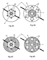
Fig.4A shows in a schematic top view radially displaceable sliding lamella segments in damping position; -
Fig.4B shows sliding lamella segments ofFig.4B in free position; -
Fig.4C shows a variant ofFig.4A having a large rotary lamella; -
Fig.4D shows the sliding lamella segments ofFig.4C in free position; -
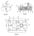
Fig.5A shows in side view the adjustable damper device with housing and adjustment device in free position; -
Fig.5B shows in side view, in cross-section, the adjustable damper device ofFig.5A ; -
Fig.5C shows in top view, in cross-section, the adjustable damper device ofFig. 5A ; -
Fig.6A - Fig.6C show the adjustable damper device ofFig.5A - 5C in damping position. -
Fig.1A shows in cross-section in side view theadjustable damper device 1 according to theinvention having housing 3 and a rotary shaft orrotor 4, extending out of the housing. This rotor may be connected to an object to be dampened, like a door, with a gear-wheel or sprocket so that the rotation - or a linear movement converted into a rotary movement - may be dampened. For that purpose the interior space 2 (seeFig.1B ) is provided with a dampening liquid like silicon oil. In the embodiment shown inFig.1A therotor 4 within theinterior space 2 of thehousing 3 is provided with an axel stub or shaft bearing, alternatively this rotor may also be passed through the opposite wall or through both walls.Rotor 4 is provided with alamella bundle 5, which comprises at least onerotary lamella 6. Preferablyrotary lamella 6 is a flat object or small plate having a constant diameter or thickness, but may also be provided with an alternative different shape. In the shown embodiment thefirst lamella bundle 5 comprises six rotary lamellas, extending radially with respect to therotor 4 and axially being fixedly interconnected at a regular mutual distance or clearance withrotor 4. Whenrotor 4 is rotated, for example by a closing or opening door, the rotary lamellas will be rotated and moved through the dampening oil, thereby generating shear forces and torque on the axis so that the rotary movement is dampened. In order to increase the dampening strength and the shear forces, thesecond lamella bundle 7, which is non rotatingly fixedly connected with the housing, be radially displaced in the direction of the rotor so that the slidinglamellas 8 of thesecond lamella bundle 7 will overlap partially (or completely) therotary lamellas 6. In the embodiment shown the adjustingdevice 10 is an adjustment axis by which the wholesecond lamella bundle 7 may be displaced in the direction of therotor 4. As a result is it possible to adjust continuously variable the dampening strength of thedamper device 1. InFig.1A is furthermore shown thatrotary lamellas 6 are provided with amutual clearance 11, whereby the clearance is provided with such a dimension, that the slidinglamellas 8 may be inserted or interposed between two rotary lamellas. - In
Fig.1B is shown in cross-section in top view theadjustable damper 1 ofFig.1A having a disk-shapedrotary lamella 6 and a slidinglamella 8 in the extreme free position having the lowest dampening strength. Theadjustment axis 10 is connected with slidinglamella 8 in such a way, that at the outside of the housing the slidinglamella 8 may be displaced or shifted in the direction of therotor 4. - In
Fig.2A - 2B theadjustable damper device 1 ofFig. 1A - 1B is shown withsecond lamella bundle 7 in its extreme damping position. The slidinglamellas 8 substantially, for a major part, overlap therotary lamellas 5. Therefore the sliding lamellas are provided withrecess 9 having a dimension, which corresponds with the diameter of therotor 4, so that parts of the sliding lamella extend past therotor 4. The lamellas of thesecond lamella bundle 7 are connected by means of aconnection element 14; in the embodiment shown the connection element is aconnection plate 14, which is provided at the backside of thesecond lamella bundle 7, thereby mutually parallely connecting the sliding lamellas. - Preferably the sliding
lamellas 8 are mutually parallely mounted ontoconnection element 14 configuring a mutual clearance distance 11'. This clearance distance corresponds preferably with the dimensions ofclearance 11 of thefirst lamella bundle 5 so that the lamella bundles may easily be stacked, interposed or be slid together. -
Fig.3A shows schematically an embodiment according to the invention having a disk shapedrotary lamella 6 mounted uponrotor 4 and a radially adjustable slidinglamella 8, provided with arecess 9 corresponding to the dimensions (diameter) of therotor 4. -
Fig.3B shows an alternative embodiment having two slidinglamella segments 12 on both sides ofrotor 4. The slidinglamella segments 12 are each radially adjustable with respect to therotor 4 and may each be provided with acircular recess 9 so that a complete overlap of the surface of therotary lamella 6 by the surface of the sliding lamella segments is possible. -
Fig.3C shows an alternative embodiment of the example ofFig.3B whereby the left slidinglamella segment 12 is fixed and not adjustable and theright sliding lamella 12 is radially adjustable and displaceable in order to be able to adjust the dampening strength of the damper. -
Fig.3D shows an alternative embodiment, whereby the slidinglamella segments 12 ofFig.3B & 3C are tilted towards and from therotor 4, so that in this way a complete overlap of therotary lamella 6 is also possible. -
Fig.4A - 4D show an alternative of theadjustable damper device 1 according to theinvention having housing 3 provided with a circular cross-section. The slidinglamella 8 is subdivided into six slidinglamella segments 12 which may each be radially displaced with respect to therotor 4. InFig.4A is shown how in the damping position the slidinglamella segments 12 constitute acircular disk 13 aroundrotor 4. With alternative solution it is also possible to cover or overlap the entire surface area of therotary lamella 6. The side of the sliding lamella segment, which abuts or contacts therotor 4, is provided with a concave circular shape, corresponding to the outward shape of therotor 4. InFig.4C en 4D is shown thatrotary lamella 6 is extending over the entire cross-section of thehousing 3, so that the slidinglamellas 12 cannot be adjusted or displaced out of axial position adjacently to the surface area of therotary lamella 6. -
Fig.5A and cross-section 5A en 5B show more in detail the advantageous embodiment of the invention ofFig.1A - 2B with a, at least basically,square housing 3, having two cylindricalconvex side walls rotor 4, which extends out of from the upper side of thehousing 9 and which is supported on bearings upon thelower wall 19. The adjusting mechanism is an adjustingaxis 10 which by means of cooperating threading 15 and rotating thereof adjusts thesecond lamella bundle 8 between therotary lamellas 6 of the first lamella bundle. Therotor 4 is positioned onto the right hand sidenearby side wall 16 and thesecond lamella bundle 7 is positioned nearby theopposite side wall 17. The rotary lamellas 6 are circular disks and theside wall 16 is accordingly provided with a concave circular shape so that the rotary lamellas may closely fit onto the wall. The slidinglamellas 8 of the second lamella bundle are at their outer end also provided with a conforming circular shape. -
Fig 6A and cross-sections 6A en 6B show in more detail the embodiment ofFig.5A - 5C in closed, damping position, whereby the overlap between therotary lamella 6 and the slidinglamella 8 is at its maximum. The sliding lamella is provided with arecess 9 for receiving therotor 4, so that theouter end 18 of the sliding lamella also closely fits onto theside wall 16 of thehousing 3.
Claims (13)
- Adjustable damper device (1) comprising:- a housing (3) provided with an internal space (2) for receiving a dampening fluid;- a rotor (4) extending into the internal space (2) of the housing (3) and being disposed rotatably within the housing (3);- the internal space (2) being provided with:- a first lamella bundle (5) comprising at least one rotary lamella (6) being connected with the rotor (4) and essentially radially extending relatively to the rotor (4) and being rotatable relatively to the housing (2),- a second lamella bundle (7) comprising at least one sliding lamella (8) being connected with the housing (2) and essentially extending parallely to the rotary lamella (6);- an adjustment device (10) for radially displacing the second lamella bundle (7) relatively to the rotor (4);characterized in,
the second lamella bundle (7) being adjustable between:- a damping position whereby a substantial portion of the surface area of the sliding lamella (8) is axially positioned adjacently with respect to the surface area of the rotary lamella (6), and- a free position whereby a substantial portion of the surface area of the sliding lamella (8) is radially positioned distantly with respect to the surface area of the rotary lamella (6). - Adjustable damper device according to claim 1, wherein in the damping position the surface areas of the lamellas of the first and the second lamella bundle in axial direction have maximum overlap.
- Adjustable damper device according to claims 2 - 3, wherein the sliding lamella (8) is provided with a recess (9) having a size corresponding to the diameter of the rotor (4), so that the sliding lamella (8) is configured to be displaceable past the rotor (4).
- Adjustable damper device according to anyone of the preceding claims 1 - 3, wherein the sliding lamella (8) is radially adjustable relative to the rotor (4) or the sliding lamella is tiltable towards and from the rotor (4).
- Adjustable damper device according to anyone of the preceding claims 1 - 4, wherein the first lamella bundle (5) is configured by two or more rotary lamellas (6) which are axially parallelly mounted upon the rotor (4) having a rotary lamella clearance distance (11) such that the sliding lamellas (8) of the second lamella bundle (7) may be introduced into the rotary lamella clearance (11).
- Adjustable damper device according to anyone of the preceding claims 1 - 5 wherein the sliding lamella (8) is formed by two or more sliding lamella segments (12), preferably the sliding lamella segments (12) are circle segments which form circular disks (13) in the damping position.
- Adjustable damper device according to anyone of the preceding claims 1 - 6, wherein the second lamella bundle (7) is provided with a connection element, like a connection plate (14), where upon the sliding lamellas (8) are essentially parallelly mounted having a sliding lamella clearance (11').
- Adjustable damper according to claim 7, wherein the adjustment device (10) is an adjusting axis, which extends outside the housing (3), by which the second lamella bundle (7) may be radially adjusted, with respect to the rotor (4).
- Adjustable damper device according to claim 8, wherein the adjusting axis (10) and the connection plate (14) of the second lamella bundle (7) are provided with cooperating threading (15) such that by rotating the adjustment axis (10) the second lamella bundle (7) is radially displaced with respect to the rotor (4) within the interior space (2) of the housing (3).
- Adjustable damper device according to anyone of the preceding claims 9, wherein the rotor (4) with the first lamella bundle (5) is mounted adjacently to the side wall (16) of the interior space (2) of the housing (3) and the second lamella bundle (7) with the connection element (14) is mounted adjacently to the opposite side wall (17).
- Adjustable damper device according to claim 10, wherein the first lamella bundle (5) is formed by circular rotary lamellas (6) and that the adjacent side wall (16) is conformingly concavely circularly shaped and that the sliding lamellas (8) of the second lamella bundle (7) at their outer ends (18) are also provided with a conformingly circular shape.
- Adjustable damper device according to claim 7, wherein the single lamellas can also be adjusted independently.
- Adjustable damper device according to claim 9, wherein the adjusting axis (10) and the connection plate (14) of the second lamella bundle (7) can alternatively be provided with a pushing/pulling mechanism without a thread.
Applications Claiming Priority (1)
| Application Number | Priority Date | Filing Date | Title |
|---|---|---|---|
| NL1037131A NL1037131C2 (en) | 2009-07-20 | 2009-07-20 | ADJUSTABLE DAMPER. |
Publications (2)
| Publication Number | Publication Date |
|---|---|
| EP2278184A1 true EP2278184A1 (en) | 2011-01-26 |
| EP2278184B1 EP2278184B1 (en) | 2014-10-08 |
Family
ID=41478639
Family Applications (1)
| Application Number | Title | Priority Date | Filing Date |
|---|---|---|---|
| EP10007433.5A Active EP2278184B1 (en) | 2009-07-20 | 2010-07-19 | Adjustable damper device |
Country Status (3)
| Country | Link |
|---|---|
| EP (1) | EP2278184B1 (en) |
| ES (1) | ES2527328T3 (en) |
| NL (1) | NL1037131C2 (en) |
Cited By (1)
| Publication number | Priority date | Publication date | Assignee | Title |
|---|---|---|---|---|
| CN113790241A (en) * | 2021-10-20 | 2021-12-14 | 湖南科技大学 | Variable-damping rotary damper |
Citations (5)
| Publication number | Priority date | Publication date | Assignee | Title |
|---|---|---|---|---|
| JPS6367437A (en) | 1986-09-09 | 1988-03-26 | Nhk Spring Co Ltd | Speed regulating mechanism |
| WO1988010377A1 (en) * | 1987-06-22 | 1988-12-29 | Sugatsune Industrial Co., Ltd. | Damper having a plurality of rotary coaxial cylindrical walls and using viscous fluid |
| US4938322A (en) * | 1987-06-10 | 1990-07-03 | Sugatsune Industrial Co., Ltd. | Multi-disc damper using viscous fluid |
| US5301775A (en) * | 1993-06-29 | 1994-04-12 | Illinois Tool Works Inc. | Adjustable high torque damper device |
| GB2282863A (en) * | 1993-10-14 | 1995-04-19 | Vinten Group Plc | Mountings providing at least one axis of movement with damping |
-
2009
- 2009-07-20 NL NL1037131A patent/NL1037131C2/en not_active IP Right Cessation
-
2010
- 2010-07-19 EP EP10007433.5A patent/EP2278184B1/en active Active
- 2010-07-19 ES ES10007433.5T patent/ES2527328T3/en active Active
Patent Citations (5)
| Publication number | Priority date | Publication date | Assignee | Title |
|---|---|---|---|---|
| JPS6367437A (en) | 1986-09-09 | 1988-03-26 | Nhk Spring Co Ltd | Speed regulating mechanism |
| US4938322A (en) * | 1987-06-10 | 1990-07-03 | Sugatsune Industrial Co., Ltd. | Multi-disc damper using viscous fluid |
| WO1988010377A1 (en) * | 1987-06-22 | 1988-12-29 | Sugatsune Industrial Co., Ltd. | Damper having a plurality of rotary coaxial cylindrical walls and using viscous fluid |
| US5301775A (en) * | 1993-06-29 | 1994-04-12 | Illinois Tool Works Inc. | Adjustable high torque damper device |
| GB2282863A (en) * | 1993-10-14 | 1995-04-19 | Vinten Group Plc | Mountings providing at least one axis of movement with damping |
Cited By (1)
| Publication number | Priority date | Publication date | Assignee | Title |
|---|---|---|---|---|
| CN113790241A (en) * | 2021-10-20 | 2021-12-14 | 湖南科技大学 | Variable-damping rotary damper |
Also Published As
| Publication number | Publication date |
|---|---|
| NL1037131C2 (en) | 2011-01-24 |
| ES2527328T3 (en) | 2015-01-22 |
| EP2278184B1 (en) | 2014-10-08 |
Similar Documents
| Publication | Publication Date | Title |
|---|---|---|
| US9115519B2 (en) | Damping structure | |
| JP6009094B2 (en) | Drive device | |
| US4908905A (en) | Rotary damper | |
| US20190085936A1 (en) | Torque fluctuation inhibiting device, torque converter and power transmission device | |
| RS57498B1 (en) | Hinge device for doors, shutters and the like | |
| JP6542806B2 (en) | Motorized valve | |
| JP4660711B2 (en) | Continuously adjustable winding transmission | |
| CN102966282B (en) | Rotary damper | |
| EP2606193A1 (en) | Improvements in damped hinge assemblies | |
| WO2018025373A1 (en) | Electric valve | |
| JP2016509641A (en) | Trunnion door hinge | |
| JP6616864B2 (en) | Damper | |
| EP2278184B1 (en) | Adjustable damper device | |
| US20090126561A1 (en) | Swash plate pivot bearing | |
| JP2021071190A (en) | Torque fluctuation inhibition device and power transmission device | |
| WO2016073696A1 (en) | Rotational vibration damper | |
| CN109105345A (en) | double-bearing reel | |
| US8677562B2 (en) | Movements controlling means | |
| JP4709096B2 (en) | Rotating damper device | |
| US20070186709A1 (en) | Rotation drive | |
| WO2015112559A1 (en) | Rotary vibration absorber | |
| EP1620627B1 (en) | Movements controlling means | |
| US787080A (en) | Variable-speed gearing. | |
| US11512516B2 (en) | Braking device for a movable door leaf and door closer having such a braking device | |
| CN104100668B (en) | Speed control unit |
Legal Events
| Date | Code | Title | Description |
|---|---|---|---|
| PUAI | Public reference made under article 153(3) epc to a published international application that has entered the european phase |
Free format text: ORIGINAL CODE: 0009012 |
|
| 17P | Request for examination filed |
Effective date: 20100719 |
|
| AK | Designated contracting states |
Kind code of ref document: A1 Designated state(s): AL AT BE BG CH CY CZ DE DK EE ES FI FR GB GR HR HU IE IS IT LI LT LU LV MC MK MT NL NO PL PT RO SE SI SK SM TR |
|
| AX | Request for extension of the european patent |
Extension state: BA ME RS |
|
| 17Q | First examination report despatched |
Effective date: 20121204 |
|
| GRAP | Despatch of communication of intention to grant a patent |
Free format text: ORIGINAL CODE: EPIDOSNIGR1 |
|
| INTG | Intention to grant announced |
Effective date: 20131212 |
|
| GRAP | Despatch of communication of intention to grant a patent |
Free format text: ORIGINAL CODE: EPIDOSNIGR1 |
|
| INTG | Intention to grant announced |
Effective date: 20140512 |
|
| GRAS | Grant fee paid |
Free format text: ORIGINAL CODE: EPIDOSNIGR3 |
|
| GRAA | (expected) grant |
Free format text: ORIGINAL CODE: 0009210 |
|
| AK | Designated contracting states |
Kind code of ref document: B1 Designated state(s): AL AT BE BG CH CY CZ DE DK EE ES FI FR GB GR HR HU IE IS IT LI LT LU LV MC MK MT NL NO PL PT RO SE SI SK SM TR |
|
| REG | Reference to a national code |
Ref country code: GB Ref legal event code: FG4D |
|
| REG | Reference to a national code |
Ref country code: AT Ref legal event code: REF Ref document number: 690810 Country of ref document: AT Kind code of ref document: T Effective date: 20141015 Ref country code: CH Ref legal event code: EP |
|
| REG | Reference to a national code |
Ref country code: IE Ref legal event code: FG4D |
|
| REG | Reference to a national code |
Ref country code: DE Ref legal event code: R096 Ref document number: 602010019330 Country of ref document: DE Effective date: 20141120 |
|
| REG | Reference to a national code |
Ref country code: CH Ref legal event code: NV Representative=s name: ISLER AND PEDRAZZINI AG, CH |
|
| REG | Reference to a national code |
Ref country code: NL Ref legal event code: T3 |
|
| REG | Reference to a national code |
Ref country code: ES Ref legal event code: FG2A Ref document number: 2527328 Country of ref document: ES Kind code of ref document: T3 Effective date: 20150122 |
|
| REG | Reference to a national code |
Ref country code: LT Ref legal event code: MG4D |
|
| PG25 | Lapsed in a contracting state [announced via postgrant information from national office to epo] |
Ref country code: LT Free format text: LAPSE BECAUSE OF FAILURE TO SUBMIT A TRANSLATION OF THE DESCRIPTION OR TO PAY THE FEE WITHIN THE PRESCRIBED TIME-LIMIT Effective date: 20141008 Ref country code: NO Free format text: LAPSE BECAUSE OF FAILURE TO SUBMIT A TRANSLATION OF THE DESCRIPTION OR TO PAY THE FEE WITHIN THE PRESCRIBED TIME-LIMIT Effective date: 20150108 Ref country code: IS Free format text: LAPSE BECAUSE OF FAILURE TO SUBMIT A TRANSLATION OF THE DESCRIPTION OR TO PAY THE FEE WITHIN THE PRESCRIBED TIME-LIMIT Effective date: 20150208 Ref country code: FI Free format text: LAPSE BECAUSE OF FAILURE TO SUBMIT A TRANSLATION OF THE DESCRIPTION OR TO PAY THE FEE WITHIN THE PRESCRIBED TIME-LIMIT Effective date: 20141008 Ref country code: PT Free format text: LAPSE BECAUSE OF FAILURE TO SUBMIT A TRANSLATION OF THE DESCRIPTION OR TO PAY THE FEE WITHIN THE PRESCRIBED TIME-LIMIT Effective date: 20150209 |
|
| PG25 | Lapsed in a contracting state [announced via postgrant information from national office to epo] |
Ref country code: GR Free format text: LAPSE BECAUSE OF FAILURE TO SUBMIT A TRANSLATION OF THE DESCRIPTION OR TO PAY THE FEE WITHIN THE PRESCRIBED TIME-LIMIT Effective date: 20150109 Ref country code: SE Free format text: LAPSE BECAUSE OF FAILURE TO SUBMIT A TRANSLATION OF THE DESCRIPTION OR TO PAY THE FEE WITHIN THE PRESCRIBED TIME-LIMIT Effective date: 20141008 Ref country code: HR Free format text: LAPSE BECAUSE OF FAILURE TO SUBMIT A TRANSLATION OF THE DESCRIPTION OR TO PAY THE FEE WITHIN THE PRESCRIBED TIME-LIMIT Effective date: 20141008 Ref country code: CY Free format text: LAPSE BECAUSE OF FAILURE TO SUBMIT A TRANSLATION OF THE DESCRIPTION OR TO PAY THE FEE WITHIN THE PRESCRIBED TIME-LIMIT Effective date: 20141008 Ref country code: LV Free format text: LAPSE BECAUSE OF FAILURE TO SUBMIT A TRANSLATION OF THE DESCRIPTION OR TO PAY THE FEE WITHIN THE PRESCRIBED TIME-LIMIT Effective date: 20141008 Ref country code: PL Free format text: LAPSE BECAUSE OF FAILURE TO SUBMIT A TRANSLATION OF THE DESCRIPTION OR TO PAY THE FEE WITHIN THE PRESCRIBED TIME-LIMIT Effective date: 20141008 |
|
| REG | Reference to a national code |
Ref country code: DE Ref legal event code: R097 Ref document number: 602010019330 Country of ref document: DE |
|
| PG25 | Lapsed in a contracting state [announced via postgrant information from national office to epo] |
Ref country code: DK Free format text: LAPSE BECAUSE OF FAILURE TO SUBMIT A TRANSLATION OF THE DESCRIPTION OR TO PAY THE FEE WITHIN THE PRESCRIBED TIME-LIMIT Effective date: 20141008 Ref country code: CZ Free format text: LAPSE BECAUSE OF FAILURE TO SUBMIT A TRANSLATION OF THE DESCRIPTION OR TO PAY THE FEE WITHIN THE PRESCRIBED TIME-LIMIT Effective date: 20141008 Ref country code: EE Free format text: LAPSE BECAUSE OF FAILURE TO SUBMIT A TRANSLATION OF THE DESCRIPTION OR TO PAY THE FEE WITHIN THE PRESCRIBED TIME-LIMIT Effective date: 20141008 Ref country code: RO Free format text: LAPSE BECAUSE OF FAILURE TO SUBMIT A TRANSLATION OF THE DESCRIPTION OR TO PAY THE FEE WITHIN THE PRESCRIBED TIME-LIMIT Effective date: 20141008 Ref country code: SK Free format text: LAPSE BECAUSE OF FAILURE TO SUBMIT A TRANSLATION OF THE DESCRIPTION OR TO PAY THE FEE WITHIN THE PRESCRIBED TIME-LIMIT Effective date: 20141008 |
|
| PLBE | No opposition filed within time limit |
Free format text: ORIGINAL CODE: 0009261 |
|
| STAA | Information on the status of an ep patent application or granted ep patent |
Free format text: STATUS: NO OPPOSITION FILED WITHIN TIME LIMIT |
|
| 26N | No opposition filed |
Effective date: 20150709 |
|
| PG25 | Lapsed in a contracting state [announced via postgrant information from national office to epo] |
Ref country code: MC Free format text: LAPSE BECAUSE OF FAILURE TO SUBMIT A TRANSLATION OF THE DESCRIPTION OR TO PAY THE FEE WITHIN THE PRESCRIBED TIME-LIMIT Effective date: 20141008 Ref country code: SI Free format text: LAPSE BECAUSE OF FAILURE TO SUBMIT A TRANSLATION OF THE DESCRIPTION OR TO PAY THE FEE WITHIN THE PRESCRIBED TIME-LIMIT Effective date: 20141008 |
|
| PG25 | Lapsed in a contracting state [announced via postgrant information from national office to epo] |
Ref country code: LU Free format text: LAPSE BECAUSE OF FAILURE TO SUBMIT A TRANSLATION OF THE DESCRIPTION OR TO PAY THE FEE WITHIN THE PRESCRIBED TIME-LIMIT Effective date: 20150719 |
|
| REG | Reference to a national code |
Ref country code: IE Ref legal event code: MM4A |
|
| REG | Reference to a national code |
Ref country code: AT Ref legal event code: UEP Ref document number: 690810 Country of ref document: AT Kind code of ref document: T Effective date: 20141008 |
|
| PG25 | Lapsed in a contracting state [announced via postgrant information from national office to epo] |
Ref country code: IE Free format text: LAPSE BECAUSE OF NON-PAYMENT OF DUE FEES Effective date: 20150719 |
|
| REG | Reference to a national code |
Ref country code: FR Ref legal event code: PLFP Year of fee payment: 7 |
|
| PG25 | Lapsed in a contracting state [announced via postgrant information from national office to epo] |
Ref country code: MT Free format text: LAPSE BECAUSE OF FAILURE TO SUBMIT A TRANSLATION OF THE DESCRIPTION OR TO PAY THE FEE WITHIN THE PRESCRIBED TIME-LIMIT Effective date: 20141008 |
|
| PG25 | Lapsed in a contracting state [announced via postgrant information from national office to epo] |
Ref country code: HU Free format text: LAPSE BECAUSE OF FAILURE TO SUBMIT A TRANSLATION OF THE DESCRIPTION OR TO PAY THE FEE WITHIN THE PRESCRIBED TIME-LIMIT; INVALID AB INITIO Effective date: 20100719 Ref country code: BG Free format text: LAPSE BECAUSE OF FAILURE TO SUBMIT A TRANSLATION OF THE DESCRIPTION OR TO PAY THE FEE WITHIN THE PRESCRIBED TIME-LIMIT Effective date: 20141008 Ref country code: SM Free format text: LAPSE BECAUSE OF FAILURE TO SUBMIT A TRANSLATION OF THE DESCRIPTION OR TO PAY THE FEE WITHIN THE PRESCRIBED TIME-LIMIT Effective date: 20141008 |
|
| REG | Reference to a national code |
Ref country code: FR Ref legal event code: PLFP Year of fee payment: 8 |
|
| PG25 | Lapsed in a contracting state [announced via postgrant information from national office to epo] |
Ref country code: TR Free format text: LAPSE BECAUSE OF FAILURE TO SUBMIT A TRANSLATION OF THE DESCRIPTION OR TO PAY THE FEE WITHIN THE PRESCRIBED TIME-LIMIT Effective date: 20141008 |
|
| PG25 | Lapsed in a contracting state [announced via postgrant information from national office to epo] |
Ref country code: BE Free format text: LAPSE BECAUSE OF FAILURE TO SUBMIT A TRANSLATION OF THE DESCRIPTION OR TO PAY THE FEE WITHIN THE PRESCRIBED TIME-LIMIT Effective date: 20141008 |
|
| PG25 | Lapsed in a contracting state [announced via postgrant information from national office to epo] |
Ref country code: MK Free format text: LAPSE BECAUSE OF FAILURE TO SUBMIT A TRANSLATION OF THE DESCRIPTION OR TO PAY THE FEE WITHIN THE PRESCRIBED TIME-LIMIT Effective date: 20141008 |
|
| REG | Reference to a national code |
Ref country code: FR Ref legal event code: PLFP Year of fee payment: 9 |
|
| PG25 | Lapsed in a contracting state [announced via postgrant information from national office to epo] |
Ref country code: AL Free format text: LAPSE BECAUSE OF FAILURE TO SUBMIT A TRANSLATION OF THE DESCRIPTION OR TO PAY THE FEE WITHIN THE PRESCRIBED TIME-LIMIT Effective date: 20141008 |
|
| P01 | Opt-out of the competence of the unified patent court (upc) registered |
Effective date: 20230527 |
|
| PGFP | Annual fee paid to national office [announced via postgrant information from national office to epo] |
Ref country code: NL Payment date: 20250721 Year of fee payment: 16 |
|
| PGFP | Annual fee paid to national office [announced via postgrant information from national office to epo] |
Ref country code: ES Payment date: 20250826 Year of fee payment: 16 |
|
| PGFP | Annual fee paid to national office [announced via postgrant information from national office to epo] |
Ref country code: DE Payment date: 20250722 Year of fee payment: 16 |
|
| PGFP | Annual fee paid to national office [announced via postgrant information from national office to epo] |
Ref country code: IT Payment date: 20250724 Year of fee payment: 16 |
|
| PGFP | Annual fee paid to national office [announced via postgrant information from national office to epo] |
Ref country code: GB Payment date: 20250722 Year of fee payment: 16 |
|
| PGFP | Annual fee paid to national office [announced via postgrant information from national office to epo] |
Ref country code: FR Payment date: 20250725 Year of fee payment: 16 Ref country code: AT Payment date: 20250722 Year of fee payment: 16 |
|
| PGFP | Annual fee paid to national office [announced via postgrant information from national office to epo] |
Ref country code: CH Payment date: 20250801 Year of fee payment: 16 |