EP2278133A2 - Misch- und/oder Verdampfungseinrichtung - Google Patents
Misch- und/oder Verdampfungseinrichtung Download PDFInfo
- Publication number
- EP2278133A2 EP2278133A2 EP10167377A EP10167377A EP2278133A2 EP 2278133 A2 EP2278133 A2 EP 2278133A2 EP 10167377 A EP10167377 A EP 10167377A EP 10167377 A EP10167377 A EP 10167377A EP 2278133 A2 EP2278133 A2 EP 2278133A2
- Authority
- EP
- European Patent Office
- Prior art keywords
- mixing
- wall
- leading edge
- trailing edge
- profile
- Prior art date
- Legal status (The legal status is an assumption and is not a legal conclusion. Google has not performed a legal analysis and makes no representation as to the accuracy of the status listed.)
- Granted
Links
- 238000009834 vaporization Methods 0.000 title 1
- 238000001704 evaporation Methods 0.000 claims description 42
- 230000008020 evaporation Effects 0.000 claims description 24
- 239000002184 metal Substances 0.000 claims description 18
- 238000002485 combustion reaction Methods 0.000 claims description 8
- 230000007423 decrease Effects 0.000 claims description 6
- 230000004323 axial length Effects 0.000 claims description 4
- 239000007789 gas Substances 0.000 description 35
- QGZKDVFQNNGYKY-UHFFFAOYSA-N Ammonia Chemical compound N QGZKDVFQNNGYKY-UHFFFAOYSA-N 0.000 description 12
- 238000002347 injection Methods 0.000 description 12
- 239000007924 injection Substances 0.000 description 12
- 230000003197 catalytic effect Effects 0.000 description 8
- 239000003054 catalyst Substances 0.000 description 7
- XSQUKJJJFZCRTK-UHFFFAOYSA-N Urea Chemical compound NC(N)=O XSQUKJJJFZCRTK-UHFFFAOYSA-N 0.000 description 6
- 229910021529 ammonia Inorganic materials 0.000 description 6
- 239000004202 carbamide Substances 0.000 description 6
- 239000000446 fuel Substances 0.000 description 6
- 239000007788 liquid Substances 0.000 description 6
- 230000003647 oxidation Effects 0.000 description 6
- 238000007254 oxidation reaction Methods 0.000 description 6
- 238000011144 upstream manufacturing Methods 0.000 description 6
- 238000006460 hydrolysis reaction Methods 0.000 description 5
- 238000004519 manufacturing process Methods 0.000 description 5
- 238000007493 shaping process Methods 0.000 description 4
- 239000000243 solution Substances 0.000 description 4
- 230000000694 effects Effects 0.000 description 3
- 230000007062 hydrolysis Effects 0.000 description 3
- MWUXSHHQAYIFBG-UHFFFAOYSA-N nitrogen oxide Inorganic materials O=[N] MWUXSHHQAYIFBG-UHFFFAOYSA-N 0.000 description 3
- 230000009471 action Effects 0.000 description 2
- 239000003638 chemical reducing agent Substances 0.000 description 2
- 230000001419 dependent effect Effects 0.000 description 2
- 230000018109 developmental process Effects 0.000 description 2
- 239000000376 reactant Substances 0.000 description 2
- WTHDKMILWLGDKL-UHFFFAOYSA-N urea;hydrate Chemical compound O.NC(N)=O WTHDKMILWLGDKL-UHFFFAOYSA-N 0.000 description 2
- 235000010678 Paulownia tomentosa Nutrition 0.000 description 1
- 240000002834 Paulownia tomentosa Species 0.000 description 1
- 238000005452 bending Methods 0.000 description 1
- 230000015556 catabolic process Effects 0.000 description 1
- 230000008859 change Effects 0.000 description 1
- 238000007599 discharging Methods 0.000 description 1
- 230000002349 favourable effect Effects 0.000 description 1
- 230000003993 interaction Effects 0.000 description 1
- 238000002955 isolation Methods 0.000 description 1
- 230000002045 lasting effect Effects 0.000 description 1
- 239000000203 mixture Substances 0.000 description 1
- 239000002245 particle Substances 0.000 description 1
- 230000008929 regeneration Effects 0.000 description 1
- 238000011069 regeneration method Methods 0.000 description 1
- 230000003584 silencer Effects 0.000 description 1
- 239000007858 starting material Substances 0.000 description 1
- 230000007704 transition Effects 0.000 description 1
- XLYOFNOQVPJJNP-UHFFFAOYSA-N water Substances O XLYOFNOQVPJJNP-UHFFFAOYSA-N 0.000 description 1
Images


Classifications
-
- F—MECHANICAL ENGINEERING; LIGHTING; HEATING; WEAPONS; BLASTING
- F01—MACHINES OR ENGINES IN GENERAL; ENGINE PLANTS IN GENERAL; STEAM ENGINES
- F01N—GAS-FLOW SILENCERS OR EXHAUST APPARATUS FOR MACHINES OR ENGINES IN GENERAL; GAS-FLOW SILENCERS OR EXHAUST APPARATUS FOR INTERNAL COMBUSTION ENGINES
- F01N3/00—Exhaust or silencing apparatus having means for purifying, rendering innocuous, or otherwise treating exhaust
- F01N3/08—Exhaust or silencing apparatus having means for purifying, rendering innocuous, or otherwise treating exhaust for rendering innocuous
- F01N3/10—Exhaust or silencing apparatus having means for purifying, rendering innocuous, or otherwise treating exhaust for rendering innocuous by thermal or catalytic conversion of noxious components of exhaust
- F01N3/18—Exhaust or silencing apparatus having means for purifying, rendering innocuous, or otherwise treating exhaust for rendering innocuous by thermal or catalytic conversion of noxious components of exhaust characterised by methods of operation; Control
- F01N3/20—Exhaust or silencing apparatus having means for purifying, rendering innocuous, or otherwise treating exhaust for rendering innocuous by thermal or catalytic conversion of noxious components of exhaust characterised by methods of operation; Control specially adapted for catalytic conversion ; Methods of operation or control of catalytic converters
- F01N3/2066—Selective catalytic reduction [SCR]
-
- B—PERFORMING OPERATIONS; TRANSPORTING
- B01—PHYSICAL OR CHEMICAL PROCESSES OR APPARATUS IN GENERAL
- B01F—MIXING, e.g. DISSOLVING, EMULSIFYING OR DISPERSING
- B01F23/00—Mixing according to the phases to be mixed, e.g. dispersing or emulsifying
- B01F23/20—Mixing gases with liquids
- B01F23/21—Mixing gases with liquids by introducing liquids into gaseous media
- B01F23/213—Mixing gases with liquids by introducing liquids into gaseous media by spraying or atomising of the liquids
-
- B—PERFORMING OPERATIONS; TRANSPORTING
- B01—PHYSICAL OR CHEMICAL PROCESSES OR APPARATUS IN GENERAL
- B01F—MIXING, e.g. DISSOLVING, EMULSIFYING OR DISPERSING
- B01F25/00—Flow mixers; Mixers for falling materials, e.g. solid particles
- B01F25/30—Injector mixers
- B01F25/31—Injector mixers in conduits or tubes through which the main component flows
- B01F25/313—Injector mixers in conduits or tubes through which the main component flows wherein additional components are introduced in the centre of the conduit
- B01F25/3131—Injector mixers in conduits or tubes through which the main component flows wherein additional components are introduced in the centre of the conduit with additional mixing means other than injector mixers, e.g. screens, baffles or rotating elements
-
- B—PERFORMING OPERATIONS; TRANSPORTING
- B01—PHYSICAL OR CHEMICAL PROCESSES OR APPARATUS IN GENERAL
- B01F—MIXING, e.g. DISSOLVING, EMULSIFYING OR DISPERSING
- B01F25/00—Flow mixers; Mixers for falling materials, e.g. solid particles
- B01F25/40—Static mixers
- B01F25/42—Static mixers in which the mixing is affected by moving the components jointly in changing directions, e.g. in tubes provided with baffles or obstructions
- B01F25/43—Mixing tubes, e.g. wherein the material is moved in a radial or partly reversed direction
- B01F25/431—Straight mixing tubes with baffles or obstructions that do not cause substantial pressure drop; Baffles therefor
- B01F25/4315—Straight mixing tubes with baffles or obstructions that do not cause substantial pressure drop; Baffles therefor the baffles being deformed flat pieces of material
-
- F—MECHANICAL ENGINEERING; LIGHTING; HEATING; WEAPONS; BLASTING
- F01—MACHINES OR ENGINES IN GENERAL; ENGINE PLANTS IN GENERAL; STEAM ENGINES
- F01N—GAS-FLOW SILENCERS OR EXHAUST APPARATUS FOR MACHINES OR ENGINES IN GENERAL; GAS-FLOW SILENCERS OR EXHAUST APPARATUS FOR INTERNAL COMBUSTION ENGINES
- F01N3/00—Exhaust or silencing apparatus having means for purifying, rendering innocuous, or otherwise treating exhaust
- F01N3/08—Exhaust or silencing apparatus having means for purifying, rendering innocuous, or otherwise treating exhaust for rendering innocuous
- F01N3/10—Exhaust or silencing apparatus having means for purifying, rendering innocuous, or otherwise treating exhaust for rendering innocuous by thermal or catalytic conversion of noxious components of exhaust
- F01N3/24—Exhaust or silencing apparatus having means for purifying, rendering innocuous, or otherwise treating exhaust for rendering innocuous by thermal or catalytic conversion of noxious components of exhaust characterised by constructional aspects of converting apparatus
- F01N3/28—Construction of catalytic reactors
- F01N3/2892—Exhaust flow directors or the like, e.g. upstream of catalytic device
-
- B—PERFORMING OPERATIONS; TRANSPORTING
- B01—PHYSICAL OR CHEMICAL PROCESSES OR APPARATUS IN GENERAL
- B01F—MIXING, e.g. DISSOLVING, EMULSIFYING OR DISPERSING
- B01F25/00—Flow mixers; Mixers for falling materials, e.g. solid particles
- B01F25/40—Static mixers
- B01F25/42—Static mixers in which the mixing is affected by moving the components jointly in changing directions, e.g. in tubes provided with baffles or obstructions
- B01F25/43—Mixing tubes, e.g. wherein the material is moved in a radial or partly reversed direction
- B01F25/431—Straight mixing tubes with baffles or obstructions that do not cause substantial pressure drop; Baffles therefor
- B01F25/43197—Straight mixing tubes with baffles or obstructions that do not cause substantial pressure drop; Baffles therefor characterised by the mounting of the baffles or obstructions
- B01F25/431971—Mounted on the wall
-
- Y—GENERAL TAGGING OF NEW TECHNOLOGICAL DEVELOPMENTS; GENERAL TAGGING OF CROSS-SECTIONAL TECHNOLOGIES SPANNING OVER SEVERAL SECTIONS OF THE IPC; TECHNICAL SUBJECTS COVERED BY FORMER USPC CROSS-REFERENCE ART COLLECTIONS [XRACs] AND DIGESTS
- Y02—TECHNOLOGIES OR APPLICATIONS FOR MITIGATION OR ADAPTATION AGAINST CLIMATE CHANGE
- Y02A—TECHNOLOGIES FOR ADAPTATION TO CLIMATE CHANGE
- Y02A50/00—TECHNOLOGIES FOR ADAPTATION TO CLIMATE CHANGE in human health protection, e.g. against extreme weather
- Y02A50/20—Air quality improvement or preservation, e.g. vehicle emission control or emission reduction by using catalytic converters
-
- Y—GENERAL TAGGING OF NEW TECHNOLOGICAL DEVELOPMENTS; GENERAL TAGGING OF CROSS-SECTIONAL TECHNOLOGIES SPANNING OVER SEVERAL SECTIONS OF THE IPC; TECHNICAL SUBJECTS COVERED BY FORMER USPC CROSS-REFERENCE ART COLLECTIONS [XRACs] AND DIGESTS
- Y02—TECHNOLOGIES OR APPLICATIONS FOR MITIGATION OR ADAPTATION AGAINST CLIMATE CHANGE
- Y02T—CLIMATE CHANGE MITIGATION TECHNOLOGIES RELATED TO TRANSPORTATION
- Y02T10/00—Road transport of goods or passengers
- Y02T10/10—Internal combustion engine [ICE] based vehicles
- Y02T10/12—Improving ICE efficiencies
Definitions
- the present invention relates to a mixing and / or evaporation device for an exhaust system, in particular a motor vehicle, having the features of the preamble of claim 1.
- the invention also relates to an exhaust system equipped with such a mixing and / or evaporation device.
- a liquid educt into the exhaust gas flow.
- fuel may be injected upstream of an oxidation catalyst into the exhaust gas stream to cause an exothermic combustion reaction at the downstream oxidation catalyst.
- a reducing agent such as ammonia
- ammonia are injected into the exhaust stream to reduce in a subsequently arranged SCR catalyst in the exhaust gas entrained nitrogen oxides.
- urea or an aqueous urea solution can also be injected into the exhaust gas stream.
- ammonia and water are formed from the urea-water solution.
- a fuel or other suitable reductant may be injected upstream of a NOX storage catalyst into the exhaust flow to regenerate the NOX storage catalyst.
- the exhaust system may be equipped with a mixing and / or evaporation device arranged downstream of an injection device in the exhaust line.
- Such a mixing and / or evaporating device which has a plurality of circumferentially distributed blades which project in each case from an outer wall inwardly.
- Each blade has a profile in the axial direction, at least in a region adjoining the outer wall, in which an outflow edge has an offset in the circumferential direction with respect to a leading edge. Accordingly, the blades are turned against the exhaust gas flow, whereby they can act on the exhaust gas flow with a twist.
- the present invention is concerned with the problem of providing an improved embodiment for a mixing and / or evaporating device of the aforementioned type, which is characterized in particular by a reduced flow resistance.
- the invention is based on the general idea of profiling the blades and setting them against the exhaust gas flow so that an angle of incidence relative to the axial direction or the exhaust gas flow is established for the leading edge as well as for the trailing edge, amounting to a maximum of 10 °.
- the angle of attack with respect to the exhaust gas flow is very small upstream and downstream.
- It is particularly advantageous that the tendency to impose a swirl on the mixing and / or evaporation flowing through the exhaust gas flow is significantly reduced. This has a lasting effect on the total flow resistance of the exhaust gas flow downstream of the mixing and / or evaporating device, since the spin traction impressed on the exhaust gas flow is reduced in terms of rotational energy and length.
- the profile of the blades between the leading edge and the trailing edge can have an angle of attack with respect to the axial direction or the exhaust gas flow which is greater than the angle of attack prevailing at the leading edge and at the trailing edge.
- the angle of attack of the profile at the leading edge and at the trailing edge along the respective blade can be constant from outside to inside, while an angle of attack prevailing between leading edge and trailing edge decreases along the respective blade from outside to inside.
- the respective blade is twisted in the radial direction, such that the offset present in the circumferential direction between leading edge and trailing edge decreases from radially outside to radially inside. In this case, this distortion is realized so that the leading edge and the trailing edge continue to have constant angles of attack and extend in particular straight.
- the blades are dimensioned relatively large in the axial direction, whereby a sufficient opacity in the axial direction can be realized even with a comparatively small angle of attack of the blade between leading edge and trailing edge.
- the axial length of a blade multiplied by the number of blades is greater than the circumferential length of the outer wall from which the blades project inwardly.
- the mixing and / or evaporation device can be produced from a single sheet metal part by forming. As a result, this device can be produced particularly inexpensively.
- FIG. 1 has an internal combustion engine 1, which may be arranged for example in a motor vehicle, for supplying fresh gas, preferably air, a fresh gas system 2 and for discharging exhaust gas to an exhaust system 3.
- an exhaust system 3 comprises an exhaust-gas-carrying line 4, which dissipates the exhaust gas arising therefrom from the internal combustion engine 1 during operation of the internal combustion engine 1.
- the exhaust system 3 can have at least one exhaust gas treatment device 5, which is integrated in the exhaust-gas-conducting line 4.
- This exhaust gas treatment device 5 can be, for example, an oxidation catalytic converter, an NOX storage catalytic converter, a hydrolysis reactor, an SCR catalytic converter or a particle filter act.
- the exhaust system 3 has an injection device 6 which is designed to inject a liquid educt into the exhaust-gas-conducting line 4.
- the injection device 6 is arranged on the exhaust gas-carrying line 4 upstream of the exhaust gas treatment device 5.
- the liquid starting material may preferably be fuel, in particular the same fuel with which the internal combustion engine 1 is also operated.
- the educt may also be ammonia or urea or an aqueous urea solution.
- the exhaust gas treatment device 5 immediately downstream of the injection device 6 is preferably an oxidation catalytic converter, which converts the fuel into heat, for example to bring the oxidation catalytic converter up to its operating temperature or downstream of the oxidation catalytic converter To heat the particulate filter to a regeneration temperature.
- the injection device 6 is designed for the injection of ammonia
- the exhaust gas treatment device 5 may be an SCR catalytic converter.
- the exhaust gas treatment device 5 immediately downstream may preferably be a hydrolysis reactor or hydrolysis catalyst in which the urea is converted into ammonia in order to charge a subsequent SCR catalyst.
- the injection device 6 can be followed directly by an exhaust gas treatment device 5 designed as an SCR catalytic converter, in which the hydrolysis reaction additionally takes place.
- an exhaust gas treatment device 5 designed as an SCR catalytic converter, in which the hydrolysis reaction additionally takes place.
- any other applications for the injection of a liquid reactant into the exhaust-gas-carrying line 4 with and without interaction with the exhaust gas treatment device 5 are conceivable.
- a axial alignment of the educt jet is preferred, which is realized here by way of example by a corresponding bending or angling in the exhaust-carrying line 4.
- the exhaust system 3 is equipped with a mixing and / or evaporation device 7, which is arranged in the exhaust gas line 4 , downstream of the injection device 6 and expediently upstream or directly on or in the exhaust gas treatment device 5 adjacent to the injection device 6.
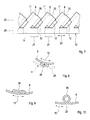
- the respective device 7 has a plurality of blades 8, which are distributed in the circumferential direction and which project inwardly from an outer wall 9 of the device 7.
- each blade has 8 in the axial section or in the axial direction a profile 10 with a leading edge 11 and a trailing edge 12.
- a prevailing during operation of the device 7 flow direction is z.
- the axial direction of the device 7 is z.
- Fig. 3 indicated by a dot-dash line and designated 14.
- the circumferential direction of the device 7 is z.
- Fig. 2 indicated by a curved double arrow 15.
- the blades 8 are profiled at least in a region adjoining the outer wall 9 such that an offset 16 exists between the leading edge 11 and the trailing edge 12 in the circumferential direction 15. This is the appropriate Blade 8 at least in this adjacent to the outer wall 9 area opposite the exhaust gas flow 13 employed.
- the profile 10 at both the leading edge 11 and at the trailing edge 12 with respect to the axial direction 14 has an angle of attack 17 which is small and in a range of -10 ° inclusive to + 10 ° inclusive.
- the angle of attack 17, the leading edge 11 and the trailing edge 12 occupy with respect to the axial direction 14, in a range of from -5 ° to + 5 ° inclusive.
- the angle of attack 17 of leading edge 11 and trailing edge 12 need not be the same. In particular, they can also have a different sign. However, an embodiment is preferred in which said angle of incidence 17 is substantially zero, so that the profile 10 is oriented at its leading edge 11 and at its trailing edge 12 substantially parallel to the axial direction 14.
- the profile 10 between leading edge 11 and trailing edge 12 has an angle of attack 18 with respect to the axial direction 14, which is greater than the prevailing at the leading edge 11 and at the trailing edge 12 Anstellwinkel 17.
- the angle of attack 18 increase between leading edge 11 and trailing edge 12 to a value of at least 30 °.
- the prevailing between leading edge 11 and trailing edge 12 angle of attack 18 of the profile 10 reaches directly on the outer wall 9 even 45 ° or about 45 °.
- the angle of incidence present between leading edge 11 and trailing edge 12 increases starting from the value prevailing at leading edge 11 up to its maximum and subsequently drops to the value prevailing at trailing edge 12.
- the profile 10 is shaped so that it is ungrounded from the leading edge 11 to the trailing edge 12 and in particular has a steady course.
- the respective profile 10 between its leading edge 11 and its trailing edge 12 has only a single point of inflection, in Fig. 3 designated 19.
- the inflection point 19 lies on an imaginary center line of the profile 10, which is located centrally between the inflow side and the outflow side of the profile 10.
- the inflection point 19 is preferably arranged centrally between leading edge 11 and trailing edge 12, so that the change in the setting angle 18 along the profile 10 in particular can increase and decrease symmetrically.
- the geometry of the blades 8 or the shaping of the profile 10 can also have a straight-line section 32, which is located between the leading edge 11 and the trailing edge 12, in particular centrally, according to FIG Fig. 4 at least directly on the outer wall 9.
- the profiling and shaping of the blades 8 also takes place such that the offset 16 present in the circumferential direction between leading edge 11 and trailing edge 12 decreases along the respective blade 8 from outside to inside. This is achieved by a twist of the respective blade 8 with respect to its radial extent.
- the twisting of the blades 8 is realized in the particular embodiments shown here so that the angle of attack 17 of the profile 10 at the leading edge 11 and at the trailing edge 12 along the respective blade 8 from outside to inside is constant. The angle of attack 17 occurring at the leading edge 11 and at the trailing edge 12 is thus the same over the entire radial extent of the blades 8.
- the angle of attack 18 prevailing between the leading edge 11 and the trailing edge 12 varies along the radial extent of the blades 8.
- Said angle of incidence 18 prevailing between the leading edge 11 and the trailing edge 12 increases along the respective blade 8 from outside to inside.
- the largest angle of attack 18 of the profile 10 prevails.
- the smallest angle of attack 18 occurs at a radially inner end of the respective blade 8 between leading edge 11 and trailing edge 12 in each case the smallest angle of attack 18, which leads to the smallest offset 16.
- the respective blade 8 has a straight end edge 20 at its end which is distal to the outer wall 9, that is to say at its inner end.
- the respective end edge 20 extends parallel to the axial direction 14.
- the inner end edges 20 of the blades 8 can be positioned very close to each other. In particular, it is possible to position the inner ends free-standing, so that the blades 8 do not touch at their inner ends.
- the blades touch 8 at their inner ends and in particular support each other.
- the blades 8 can be supported at their inner ends under bias to each other, whereby a targeted stiffening of the device 7 can be realized in the mounted state.
- the shaping of the blades 8 expediently also takes place in such a way that the leading edges 11 extend straight from the outside to the inside along the respective blade 8, ie along straight lines. Additionally or alternatively may also the trailing edges 12 along the respective blade 8 from outside to inside straight, so extend along straight lines.
- these straight leading edges 11 and the straight trailing edges 12 are exactly radially oriented, so that they extend radially in a star-shaped manner from a longitudinal central axis 21 of the device 7.
- the Fig. 2-6 show an embodiment of the device 7, in which the device 7 is made of a single sheet metal part 22 by forming, which in Fig. 7 is reproduced.
- Corresponding Fig. 7 extends in the reproduced here production state in which the sheet metal part 22 is unwound or unrolled in the plane and in a longitudinal direction 23.
- the sheet metal part 22 is designed strip-shaped, so that it also referred to as sheet metal strip 22nd can be designated.
- the blades 8 are cut or punched out. Visible are the leading edges 11, the trailing edges 12 and the straight inner end edges 20.
- the, z. Tie Fig. 2-6 recognizable, rounded transitions from the radial state in the mounted state edges, z. B. 11 and 12, to the axial in the mounted state edges, z. B. 20, not shown.
- the other (lower) longitudinal side 25 connects the individual blades 8 with each other and forms in the finished state of the device 7, the outer wall 9.
- the sheet metal strip 22 is wound in its plane transverse to its longitudinal direction 23 or rolled up, so that then the longitudinal direction 23 of the sheet metal strip 22 in the circumferential direction 15 of the outer wall 9 extends.
- the metal strip 22 and its longitudinal side 25 to perform the outer wall 9 so that the outer wall 9 associated longitudinal side 25 in the in Fig. 7 shown, not formed state is longer than the circumference of the outer wall made therefrom.
- the deformation of the metal strip 22 can be carried out so that the outer wall 9 with several, in the Fig. 2-6 recognizable Einschlingept 26 is arranged, which are arranged distributed in the circumferential direction 15. These inclinations 26 are from the in Fig. 7 formed by curly braces areas 27 of the longitudinal side 25, which is associated with the outer wall 9.
- the inclusions 26 project inwards from the outer wall 9. They are designed flat or flat fitting. In the in the Fig. 2-6 In the embodiments shown, the inclusions 26 are symmetrically shaped with respect to the circumferential direction 15.
- Fig. 8 shows a loop 26 of another embodiment in which the Einschlingungen 26 protrude from the outer wall 9 to the outside.
- the inclusions 26 in the installed state of the device 7, the outer wall 9 at an in Fig. 8 Supported by broken lines indicated inner wall 28 of the exhaust gas line 4 of the exhaust system 3. They can be shaped so that on the one hand they realize a resilient support in the radial direction and / or on the other hand enable prestressed positioning and thus also fixation of the device 7 in the conduit 4 axially.
- FIG. 9 shows an embodiment in which the Einschlingungen 26 are formed asymmetrically with respect to the circumferential direction 15 and thus in particular allow complete placement in the flow shadow of one of the blades 8. Also at the in Fig. 9 In the embodiment shown, the inclusions 26 are flat and also designed to project inward.
- Fig. 10 shows a further variant for the realization of the Einschlingungen 26.
- the shown loop 26 is inwardly from the outer wall 9 from.
- the inclusions 26 are shaped so that the outer wall 9 in the region of the respective loop 26 has a gap 29, whereby in the circumferential direction 15 a spring action with the help of the respective loop 26 can be realized, for example, to manufacturing tolerances and / or to compensate for thermal expansion effects in the circumferential direction 15.
- FIGS. 11 and 12 another embodiment in which the device 7 is not integrally formed from a single sheet metal part 22, but in which the device 7 is built.
- the device 7 has a plurality of blade parts 30, which each have at least one blade 8.
- an annular body 31 is provided which forms the outer wall 9.
- the blade parts 30 are attached to the ring body 31 so as to construct the device 7.
- the annular body 31 may be interrupted or slotted in the circumferential direction 15 at least at one point, for. B. to match manufacturing tolerances and / or thermal rotation effects in the circumferential direction 15.
- the respective blade part 30 may also comprise two or more blades 8.
- the in the FIGS. 11 and 12 shown variant of the device 7 comes without inclusions 26, which protrude from the outer wall 9 inwardly or outwardly.
Landscapes
- Chemical & Material Sciences (AREA)
- Chemical Kinetics & Catalysis (AREA)
- Engineering & Computer Science (AREA)
- Health & Medical Sciences (AREA)
- Toxicology (AREA)
- Combustion & Propulsion (AREA)
- Mechanical Engineering (AREA)
- General Engineering & Computer Science (AREA)
- Dispersion Chemistry (AREA)
- Exhaust Gas After Treatment (AREA)
Abstract
Description
- Die vorliegende Erfindung betrifft eine Misch- und/oder Verdampfungseinrichtung für eine Abgasanlage, insbesondere eines Kraftfahrzeugs, mit den Merkmalen des Oberbegriffs des Anspruchs 1. Die Erfindung betrifft außerdem eine mit einer solchen Misch- und/oder Verdampfungseinrichtung ausgestattete Abgasanlage.
- Bei Abgasanlagen von Brennkraftmaschinen kann es aus unterschiedlichen Gründen erforderlich sein, ein flüssiges Edukt in den Abgasstrom einzubringen. Beispielsweise kann Kraftstoff stromauf eines Oxidationskatalysators in den Abgasstrom eingespritzt werden, um an dem stromab nachfolgenden Oxidationskatalysator eine exotherme Verbrennungsreaktion auszulösen. Ebenso kann beispielsweise ein Reduktionsmittel, wie zum Beispiel Ammoniak, in den Abgasstrom eingespritzt werden, um in einem nachfolgend angeordneten SCR-Katalysator im Abgas mitgeführte Stickoxide zu reduzieren. Anstelle von Ammoniak kann auch Harnstoff bzw. eine wässrige Harnstofflösung in den Abgasstrom eingespritzt werden. Durch eine Hydrolyse-Reaktion entstehen aus der Harnstoff-Wasser-Lösung dann Ammoniak und Wasser. Ferner kann ein Kraftstoff oder ein anderes geeignetes Reduktionsmittel stromauf eines NOX-Speicherkatalysators in die Abgasströmung eingespritzt werden, um den NOX-Speicherkatalysator zu regenerieren.
- Um die Wirkungsweise des in flüssiger Form in den Abgasstrang eingespritzten Edukts zu verbessern bzw. zu ermöglichen, ist eine weitgehende Verdampfung ebenso erstrebenswert wie eine intensive Durchmischung mit dem Abgas, um so ein möglichst homogenes Abgas-Edukt-Gemisch zu erhalten. Hierzu kann die Abgasanlage mit einer im Abgasstrang stromab eine Einspritzeinrichtung angeordneten Misch- und/oder Verdampfungseinrichtung ausgestattet sein.
- Aus der
DE 10 2007 028 449 A1 ist eine derartige Misch- und/oder Verdampfungseinrichtung bekannt, die mehrere in Umfangsrichtung verteilt angeordnete Schaufeln aufweist, die jeweils von einer Außenwand nach innen vorstehen. Jede Schaufel weist dabei zumindest in einem an die Außenwand anschließenden Bereich in der Axialrichtung ein Profil auf, bei dem eine Abströmkante in Umfangsrichtung gegenüber einer Anströmkante einen Versatz aufweist. Dementsprechend sind die Schaufeln gegenüber der Abgasströmung angestellt, wodurch sie die Abgasströmung mit einem Drall beaufschlagen können. Ferner ist es durch das Anstellen der Schaufeln möglich, die Schaufeln so zu formen und anzuordnen, dass sie sich in Umfangsrichtung gegenseitig überlappen, wodurch eine in axialer Richtung blickdichte Ringfläche erzeugt werden kann, die einen Tröpfchendurchschlag durch die Misch- und/oder Verdampfungseinrichtung effektiv behindert oder sogar verhindert. - Die mit Hilfe einer solchen bekannten Misch- und/oder Verdampfungseinrichtung in der Abgasströmung realisierbare Verwirbelung bzw. Drallerzeugung geht jedoch mit einem Druckanstieg einher, was sich negativ auf die Leistung und auf den Wirkungsgrad einer mit der Abgasanlage ausgestatteten Brennkraftmaschine auswirkt.
- Die vorliegende Erfindung beschäftigt sich mit dem Problem, für eine Mischund/oder Verdampfungseinrichtung der eingangs genannten Art eine verbesserte Ausführungsform anzugeben, die sich insbesondere durch einen reduzierten Strömungswiderstand auszeichnet.
- Dieses Problem wird erfindungsgemäß durch die Gegenstände der unabhängigen Ansprüche gelöst. Vorteilhafte Ausführungsformen sind Gegenstand der abhängigen Ansprüche.
- Die Erfindung beruht auf dem allgemeinen Gedanken, die Schaufeln so zu profilieren und gegenüber der Abgasströmung anzustellen, dass sich sowohl für die Anströmkante als auch für die Abströmkante jeweils ein Anstellwinkel zur Axialrichtung bzw. zur Abgasströmung einstellt, der betragsmäßig maximal 10° beträgt. Mit anderen Worten, der Anstellwinkel gegenüber der Abgasströmung ist anströmseitig und abströmseitig sehr klein. In der Folge kommt es anströmseitig und abströmseitig der Schaufeln nur zu einer sehr geringen Strömungsumlenkung bzw. Strömungsablenkung. Dies führt zu einem geringen Strömungswiderstand bei der Durchströmung der Misch- und/oder Verdampfungseinrichtung. Besonders vorteilhaft ist dabei, dass die Tendenz zur Aufprägung eines Dralls auf die die Misch- und/oder Verdampfungseinrichtung durchströmende Abgasströmung signifikant reduziert ist. Dies wirkt sich nachhaltig für den Gesamtströmungswiderstand der Abgasströmung stromab der Misch- und/oder Verdampfungseinrichtung aus, da die der Abgasströmung aufgeprägte Drallschleppe hinsichtlich Rotationsenergie und Länge reduziert ist.
- Entsprechend einer vorteilhaften Ausführungsform kann das Profil der Schaufeln zwischen der Anströmkante und der Abströmkante einen Anstellwinkel gegenüber der Axialrichtung bzw. der Abgasströmung aufweisen, der größer ist als der an der Anströmkante und an der Abströmkante herrschende Anstellwinkel. Durch diese Maßnahme kann der in Umfangsrichtung vorgesehene Versatz zwischen Anströmkante und Abströmkante vergleichsweise groß ausgeführt werden, was zur Realisierung der gewünschten Überdeckung benachbarter Schaufeln in Umfangsrichtung vorteilhaft ist. Es hat sich gezeigt, dass auch bei einer derartigen Konfiguration die kleinen Anstellwinkel an der Anströmkante und an der Abströmkante günstig für einen vergleichsweise geringen Durchströmungswiderstand der Misch- und/oder Verdampfungseinrichtung sind.
- Gemäß einer anderen vorteilhaften Ausführungsform kann der Anstellwinkel des Profils an der Anströmkante und an der Abströmkante entlang der jeweiligen Schaufel von außen nach innen konstant sein, während ein zwischen Anströmkante und Abströmkante herrschender Anstellwinkel entlang der jeweiligen Schaufel von außen nach innen abnimmt. Mit anderen Worten, die jeweilige Schaufel ist in der Radialrichtung verwunden, derart, dass der in Umfangsrichtung zwischen Anströmkante und Abströmkante vorliegende Versatz von radial außen nach radial innen abnimmt. Dabei ist diese Verwindung so realisiert, dass die Anströmkante und die Abströmkante weiterhin konstante Anstellwinkel besitzen und sich insbesondere geradlinig erstrecken.
- Entsprechend einer anderen vorteilhaften Ausführungsform sind die Schaufeln in axialer Richtung relativ groß dimensioniert, wodurch auch bei einem vergleichsweise kleinen Anstellwinkel der Schaufel zwischen Anströmkante und Abströmkante eine hinreichende Blickdichtigkeit in Axialrichtung realisierbar ist. Insbesondere ist die axiale Länge einer Schaufel multipliziert mit der Anzahl der Schaufeln größer als die Umfangslänge der Außenwand, von welcher die Schaufeln nach innen abstehen.
- Entsprechend einer vorteilhaften Weiterbildung kann die Misch- und/oder Verdampfungseinrichtung aus einem einzigen Blechteil durch Umformung hergestellt sein. Hierdurch lässt sich diese Einrichtung besonders preiswert herstellen. Um auch bei einer solchen Ausführungsform die Summe der axialen Längen aller Schaufeln größer auslegen zu können, als den Umfang der Außenwand, ist es entsprechend einer vorteilhaften Weiterbildung möglich, die Außenwand mit mehreren, in Umfangsrichtung verteilt angeordneten Einschlingungen auszustatten. Durch diese Einschlingungen rücken die benachbarten Schaufeln näher zusammen, so dass in der Misch- und/oder Verdampfungseinrichtung eine größere Anzahl an Schaufeln untergebracht werden kann, wodurch insgesamt die Summe der axialen Schaufellängen vergrößert werden kann.
- Weitere wichtige Merkmale und Vorteile der Erfindung ergeben sich aus den Unteransprüchen, aus den Zeichnungen und aus der zugehörigen Figurenbeschreibung anhand der Zeichnungen.
- Es versteht sich, dass die vorstehend genannten und die nachstehend noch zu erläuternden Merkmale nicht nur in der jeweils angegebenen Kombination, sondern auch in anderen Kombinationen oder in Alleinstellung verwendbar sind, ohne den Rahmen der vorliegenden Erfindung zu verlassen.
- Bevorzugte Ausführungsbeispiele der Erfindung sind in den Zeichnungen dargestellt und werden in der nachfolgenden Beschreibung näher erläutert, wobei sich gleiche Bezugszeichen auf gleiche oder ähnliche oder funktional gleiche Bauteile beziehen.
- Es zeigen, jeweils schematisch
- Fig. 1
- eine stark vereinfachte Prinzipdarstellung einer Abgasanlage,
- Fig. 2
- eine Axialansicht einer Misch- und/oder Verdampfungseinrichtung auf deren Abströmseite,
- Fig. 3
- eine Schnittdarstellung der Misch- und/oder Verdampfungseinrich- tung entsprechend Schnittlinien III in
Fig. 2 , - Fig. 4
- eine Seitenansicht der Misch- und/oder Verdampfungseinrichtung,
- Fig. 5
- eine perspektivische Ansicht der Misch- und/oder Verdampfungs- einrichtung auf deren Abströmseite,
- Fig. 6
- eine perspektivische Ansicht wie in
Fig. 5 , jedoch auf die Anström- seite der Misch- und/oder Verdampfungseinrichtung, - Fig. 7
- eine Draufsicht auf einen Blechkörper zur Herstellung der Misch- und/oder Verdampfungseinrichtung,
- Fig. 8-10
- axiale Detailansichten im Bereich von Einschlingungen einer Au- ßenwand der Misch- und/oder Verdampfungseinrichtung,
- Fig. 11, 12
- Ansichten wie in den
Fig. 5 und 6 , jedoch bei einer anderen Ausfüh- rungsform der Misch- und/oder Verdampfungseinrichtung. - Die vorstehenden und nachstehenden absoluten Zahlenangaben für Abmessungen und Winkel sind jeweils im Rahmen der üblichen Fertigungstoleranzen zu verstehen.
- Entsprechend
Fig. 1 weist eine Brennkraftmaschine 1, die beispielsweise in einem Kraftfahrzeug angeordnet sein kann, zur Versorgung mit Frischgas, vorzugsweise Luft, eine Frischgasanlage 2 und zum Abführen von Abgas eine Abgasanlage 3 auf. Eine derartige Abgasanlage 3 umfasst eine abgasführende Leitung 4, die im Betrieb der Brennkraftmaschine 1 das dort entstehende Abgas von der Brennkraftmaschine 1 abführt. Die Abgasanlage 3 kann zumindest eine Abgasbehandlungseinrichtung 5 aufweisen, die in die abgasführende Leitung 4 eingebunden ist. Bei dieser Abgasbehandlungseinrichtung 5 kann es sich zum Beispiel um einen Oxidationskatalysator, um einen NOX-Speicherkatalysator, um einen Hydrolysereaktor, um einen SCR-Katalysator oder um ein Partikelfilter handeln. Ebenso können einzelne oder mehrere der genannten Einrichtungen in einem gemeinsamen Gehäuse, insbesondere in Verbindung mit einem Schalldämpfer, untergebracht sein. Ferner weist die Abgasanlage 3 eine Einspritzeinrichtung 6 auf, die dazu ausgestaltet ist, ein flüssiges Edukt in die abgasführende Leitung 4 einzuspritzen. Dabei ist die Einspritzeinrichtung 6 an die abgasführende Leitung 4 stromauf der Abgasbehandlungseinrichtung 5 angeordnet. Beim flüssigen Edukt kann es sich vorzugsweise um Kraftstoff handeln, insbesondere um denselben Kraftstoff, mit dem auch die Brennkraftmaschine 1 betrieben wird. Alternativ kann es sich beim Edukt auch um Ammoniak oder um Harnstoff bzw. um eine wässrige Harnstofflösung handeln. Sofern eine Kraftstoffinjektion vorgesehen ist, handelt es sich bei der unmittelbar stromab zur Einspritzeinrichtung 6 benachbarten Abgasbehandlungseinrichtung 5 vorzugsweise um einen Oxidationskatalysator, an dem eine Umsetzung des Kraftstoffs in Wärme erfolgt, beispielsweise um den Oxidationskatalysator auf seine Betriebstemperatur zu bringen oder um ein stromab des Oxidationskatalysators angeordnetes Partikelfilter auf eine Regenerationstemperatur aufzuheizen. Sofern die Einspritzeinrichtung 6 zum Einspritzen von Ammoniak ausgestaltet ist, kann es sich bei der Abgasbehandlungseinrichtung 5 um einen SCR-Katalysator handeln. Sofern Harnstoff oder eine Harnstoff-Wasser-Lösung eingedüst wird, kann es sich bei der unmittelbar stromab folgenden Abgasbehandlungseinrichtung 5 vorzugsweise um einen Hydrolysereaktor oder Hydrolyse-Katalysator handeln, in dem der Harnstoff in Ammoniak umgesetzt wird, um einen nachfolgenden SCR-Katalysator zu beaufschlagen. Ebenso kann auf die Einspritzeinrichtung 6 direkt einer als SCR-Katalysator ausgestaltete Abgasbehandlungseinrichtung 5 folgen, in der zusätzlich die Hydrolysereaktion abläuft. Darüber hinaus sind noch beliebige andere Anwendungen für die Einspritzung eines flüssigen Edukts in die abgasführende Leitung 4 mit und ohne Wechselwirkung mit der Abgasbehandlungseinrichtung 5 denkbar. - Entsprechend
Fig. 1 wird für die Eindüsung des Edukts eine axiale Ausrichtung des Eduktstrahls bevorzugt, was hier exemplarisch durch eine entsprechende Biegung oder Abwinkelung in der abgasführenden Leitung 4 realisiert ist. - Um das eingespritzte, flüssige Edukt möglichst rasch und möglichst vollständig im Abgas verdampfen zu können und um das verdampfte Edukt möglichst homogen mit dem Abgas zu vermischen, ist die Abgasanlage 3 mit einer Mischund/oder Verdampfungseinrichtung 7 ausgestattet, die in der abgasführenden Leitung 4 angeordnet ist, und zwar stromab der Einspritzeinrichtung 6 und zweckmäßig stromauf oder unmittelbar an oder in der zur Einspritzeinrichtung 6 benachbarten Abgasbehandlungseinrichtung 5.
- Bevorzugte Ausführungsformen der Misch- und/oder Verdampfungseinrichtung 7, die im Folgenden auch abgekürzt mit Einrichtung 7 bezeichnet wird, werden im Folgenden mit Bezug auf die
Fig. 2-12 näher erläutert. - Entsprechend den
Fig. 2-12 weist die jeweilige Einrichtung 7 mehrere Schaufeln 8 auf, die in Umfangsrichtung verteilt angeordnet sind und die von einer Außenwand 9 der Einrichtung 7 nach innen vorstehen. EntsprechendFig. 3 besitzt jede Schaufel 8 im Axialschnitt bzw. in der Axialrichtung ein Profil 10 mit einer Anströmkante 11 und einer Abströmkante 12. Eine im Betrieb der Einrichtung 7 vorherrschende Strömungsrichtung ist z. B. inFig. 3 durch einen Pfeil 13 angedeutet. Die Axialrichtung der Einrichtung 7 ist z. B. inFig. 3 durch eine strichpunktierte Linie angedeutet und mit 14 bezeichnet. Die Umfangsrichtung der Einrichtung 7 ist z. B. inFig. 2 durch einen gebogenen Doppelpfeil 15 angedeutet. - Die Schaufeln 8 sind zumindest in einem an die Außenwand 9 anschließenden Bereich so profiliert, dass zwischen der Anströmkante 11 und der Abströmkante 12 in der Umfangsrichtung 15 ein Versatz 16 vorliegt. Hierdurch ist die entsprechende Schaufel 8 zumindest in diesem an die Außenwand 9 angrenzenden Bereich gegenüber der Abgasströmung 13 angestellt.
- Beachtenswert ist nun, dass das Profil 10 sowohl an der Anströmkante 11 als auch an der Abströmkante 12 gegenüber der Axialrichtung 14 einen Anstellwinkel 17 aufweist, der klein ist und in einem Bereich von einschließlich -10° bis einschließlich +10° liegt. Vorzugsweise liegt der Anstellwinkel 17, den die Anströmkante 11 und die Abströmkante 12 gegenüber der Axialrichtung 14 einnehmen, in einem Bereich von einschließlich -5° bis einschließlich +5°. Dabei müssen die Anstellwinkel 17 von Anströmkante 11 und Abströmkante 12 nicht gleich sein. Insbesondere können sie auch ein unterschiedliches Vorzeichen aufweisen. Bevorzugt ist jedoch eine Ausführungsform, bei welcher besagter Anströmwinkel 17 im Wesentlichen den Wert Null besitzt, so dass das Profil 10 an seiner Anströmkante 11 und an seiner Abströmkante 12 im Wesentlichen parallel zur Axialrichtung 14 orientiert ist.
- Zur Realisierung eines vergleichsweise großen Versatzes 16 in Umfangsrichtung 15 besitzt das Profil 10 zwischen Anströmkante 11 und Abströmkante 12 einen Anstellwinkel 18 gegenüber der Axialrichtung 14, der größer ist als der an der Anströmkante 11 und an der Abströmkante 12 herrschende Anstellwinkel 17. Beispielsweise kann der Anstellwinkel 18 zwischen Anströmkante 11 und Abströmkante 12 auf einen Wert von mindestens 30° ansteigen. In den gezeigten Beispielen erreicht der zwischen Anströmkante 11 und Abströmkante 12 herrschende Anstellwinkel 18 des Profils 10 unmittelbar an der Außenwand 9 sogar 45° oder etwa 45°. Dabei steigt der zwischen Anströmkante 11 und Abströmkante 12 vorliegende Anstellwinkel 18 ausgehend von dem an der Anströmkante 11 herrschenden Wert bis zu seinem Maximum an und fällt anschließend bis zu dem an der Abströmkante 12 herrschenden Wert ab.
- Zweckmäßig ist das Profil 10 so geformt, dass es von der Anströmkante 11 bis zur Abströmkante 12 ungestuft ist und insbesondere einen stetigen Verlauf aufweist. Besonders vorteilhaft ist dabei eine Ausführungsform, bei welcher das jeweilige Profil 10 zwischen seiner Anströmkante 11 und seiner Abströmkante 12 nur einen einzigen Wendepunkt aufweist, der in
Fig. 3 mit 19 bezeichnet ist. Der Wendepunkt 19 liegt dabei auf einer gedachten Mittellinie des Profils 10, die sich mittig zwischen der Anströmseite und der Abströmseite des Profils 10 befindet. Des Weiteren ist der Wendepunkt 19 vorzugsweise mittig zwischen Anströmkante 11 und Abströmkante 12 angeordnet, so dass die Änderung des Anstellwinkels 18 entlang des Profils 10 insbesondere symmetrisch zunehmen und abnehmen kann. Dabei kann die Geometrie der Schaufeln 8 bzw. die Formgebung des Profils 10 auch einen geradlinigen Abschnitt 32 aufweisen, der sich zwischen Anströmkante 11 und Abströmkante 12, insbesondere mittig, befindet, und zwar gemäßFig. 4 zumindest unmittelbar an der Außenwand 9. - Bei den hier gezeigten, bevorzugten Ausführungsformen erfolgt die Profilierung und Formgebung der Schaufeln 8 außerdem so, dass der in Umfangsrichtung zwischen Anströmkante 11 und Abströmkante 12 vorliegende Versatz 16 entlang der jeweiligen Schaufel 8 von außen nach innen abnimmt. Erreicht wird dies durch eine Verwindung der jeweiligen Schaufel 8 bezüglich ihrer radialen Erstreckung. Die Verwindung der Schaufeln 8 wird bei den hier gezeigten, besonderen Ausführungsformen so realisiert, dass der Anstellwinkel 17 des Profils 10 an der Anströmkante 11 und an der Abströmkante 12 entlang der jeweiligen Schaufel 8 von außen nach innen konstant ist. Der an der Anströmkante 11 und an der Abströmkante 12 auftretende Anstellwinkel 17 ist somit über die gesamte radiale Erstreckung der Schaufeln 8 gleich. Im Unterschied dazu variiert jedoch der zwischen Anströmkante 11 und Abströmkante 12 herrschende Anstellwinkel 18 entlang der radialen Erstreckung der Schaufeln 8. Dabei nimmt besagter zwischen Anströmkante 11 und Abströmkante 12 herrschende Anstellwinkel 18 entlang der jeweiligen Schaufel 8 von außen nach innen ab. Somit herrscht im Bereich der Außenwand 9 zwischen Anströmkante 11 und Abströmkante 12 der größte Anstellwinkel 18 des Profils 10, wodurch dort auch der größte Versatz 16 herrscht. Im Unterschied dazu tritt an einem radial innen liegenden Ende der jeweiligen Schaufel 8 zwischen Anströmkante 11 und Abströmkante 12 jeweils der kleinste Anstellwinkel 18 auf, was zum kleinsten Versatz 16 führt.
- Besonders vorteilhaft ist dabei eine Ausführungsform, wie sie zum Beispiel in
Fig. 2 erkennbar ist, bei welcher die jeweilige Schaufel 8 an ihrem zur Außenwand 9 distalen Ende, also an ihrem innen liegenden Ende eine gerade Endkante 20 besitzt. Die jeweilige Endkante 20 erstreckt sich dabei parallel zur Axialrichtung 14. Mit anderen Worten, an dieser innen liegenden Endkante 20 ist der Anstellwinkel 17 bzw. 18 von der Anströmkante 11 bis zur Abströmkante 12 durchgehend auf den Wert Null gesetzt, so dass an der Endkante 20 keine Anstellung vorliegt und auch kein Versatz 16 zwischen Anströmkante 11 und Abströmkante 12 gegeben ist. Durch diese Formgebung können die innen liegenden Endkanten 20 der Schaufeln 8 sehr nahe aneinander positioniert werden. Insbesondere ist es möglich, die innen liegenden Enden freistehend zu positionieren, so dass sich die Schaufeln 8 an ihren innen liegenden Enden nicht berühren. - Ebenso ist eine Ausführungsform möglich, bei der sich die Schaufeln 8 an ihren innen liegenden Enden berühren und insbesondere aneinander abstützen. Bevorzugt können sich die Schaufeln 8 an ihren innen liegenden Enden unter Vorspannung aneinander abstützen, wodurch sich eine gezielte Aussteifung der Einrichtung 7 im montierten Zustand realisieren lässt.
- Die Formgebung der Schaufeln 8 erfolgt zweckmäßig außerdem so, dass sich die Anströmkanten 11 entlang der jeweiligen Schaufel 8 von außen nach innen gerade, also entlang von Geraden erstrecken. Zusätzlich oder alternativ können sich auch die Abströmkanten 12 entlang der jeweiligen Schaufel 8 von außen nach innen gerade, also entlang von Geraden erstrecken. Im Beispiel sind diese geraden Anströmkanten 11 und die geraden Abströmkanten 12 exakt radial orientiert, so dass sie sich von einer Längsmittelachse 21 der Einrichtung 7 sternförmig radial erstrecken.
- Die
Fig. 2-6 zeigen eine Ausführungsform der Einrichtung 7, bei der die Einrichtung 7 aus einem einzigen Blechteil 22 durch Umformung hergestellt ist, das inFig. 7 wiedergegeben ist. EntsprechendFig. 7 erstreckt sich das Blechteil 22 in dem hier wiedergegebenen Herstellungszustand, in dem das Blechteil 22 abgewickelt oder abgerollt ist, in der Zeichnungsebene sowie in einer Längsrichtung 23. Bezüglich dieser Längsrichtung 23 ist das Blechteil 22 streifenförmig ausgestaltet, so dass es im Folgenden auch als Blechstreifen 22 bezeichnet werden kann. Bei dem inFig. 7 gezeigten Fertigungszustand sind an einer (oberen) Längsseite 24 des Blechstreifens 22 bereits die Schaufeln 8 freigeschnitten oder ausgestanzt. Erkennbar sind die Anströmkanten 11, die Abströmkanten 12 und die geraden inneren Endkanten 20. Zur vereinfachten Darstellung sind inFig. 7 die, z. B. in denFig. 2-6 erkennbaren, abgerundeten Übergänge von den im montierten Zustand radialen Kanten, z. B. 11 und 12, zu den im montierten Zustand axialen Kanten, z. B. 20, nicht dargestellt. - Die andere (untere) Längsseite 25 verbindet die einzelnen Schaufeln 8 miteinander und bildet im fertigen Zustand der Einrichtung 7 die Außenwand 9. Hierzu wird der Blechstreifen 22 in seiner Ebene quer zu seiner Längsrichtung 23 aufgewickelt bzw. aufgerollt, derart, dass sich anschließend die Längsrichtung 23 des Blechstreifens 22 in der Umfangsrichtung 15 der Außenwand 9 erstreckt.
- Um nun eine möglichst große Anzahl an Schaufeln 8 entlang der Außenwand 9 unterbringen zu können, kann es zweckmäßig sein, die Umformung des Blechstreifens 22 bzw. seiner Längsseite 25 zur Außenwand 9 so durchzuführen, dass die der Außenwand 9 zugeordnete Längsseite 25 in dem in
Fig. 7 gezeigten, nicht umgeformten Zustand länger ist als der Umfang der daraus hergestellten Außenwand 9. Hierzu kann die Umformung des Blechstreifens 22 so durchgeführt werden, dass die Außenwand 9 mit mehreren, in denFig. 2-6 erkennbaren Einschlingungen 26 ausgestattet wird, die in der Umfangsrichtung 15 verteilt angeordnet sind. Diese Einschlingungen 26 werden dabei aus den inFig. 7 durch geschweifte Klammern gekennzeichneten Bereichen 27 der Längsseite 25 gebildet, welche der Außenwand 9 zugeordnet ist. Diese Bereiche oder Abschnitte 27 erstrecken sich dabei in der Längsrichtung 23 dieser der Außenwand 9 zugeordneten Längsseite 25 zwischen aufeinanderfolgenden Schaufeln 8. Hierdurch lässt sich besonders einfach eine Ausführungsform für die Einrichtung 7 realisieren, die aus einem einzigen Blechformteil (Blechstreifen 22) besteht und bei der die axiale Länge einer Schaufel 8 multipliziert mit der Anzahl der Schaufeln 8 größer ist als die Umfangslänge der Außenwand 9. - Bei der in den
Fig. 2-6 gezeigten Ausführungsform stehen die Einschlingungen 26 von der Außenwand 9 nach innen ab. Dabei sind sie flach bzw. flächig anliegend ausgestaltet. Bei den in denFig. 2-6 gezeigten Ausführungsformen sind die Einschlingungen 26 bezüglich der Umfangsrichtung 15 symmetrisch geformt. -
Fig. 8 zeigt eine Einschlingung 26 einer anderen Ausführungsform, bei welcher die Einschlingungen 26 von der Außenwand 9 nach außen abstehen. Dabei können die Einschlingungen 26 im Einbauzustand der Einrichtung 7 die Außenwand 9 an einer inFig. 8 durch unterbrochene Linien angedeuteten Innenwand 28 der abgasführenden Leitung 4 der Abgasanlage 3 abstützen. Sie können dabei so geformt sein, dass sie in der Radialrichtung einerseits eine federelastische Abstützung realisieren und/oder andererseits eine vorgespannte Positionierung und somit Fixierung auch axial der Einrichtung 7 in der Leitung 4 ermöglichen. - Besonders vorteilhaft ist eine Ausführungsform, bei welcher die Einschlingungen 26 möglichst weitgehend im Strömungsschatten der jeweiligen Schaufeln 8 angeordnet sind.
Fig. 9 zeigt eine Ausführungsform, bei welcher die Einschlingungen 26 bezüglich der Umfangsrichtung 15 asymmetrisch geformt sind und somit insbesondere eine vollständige Unterbringung im Strömungsschatten einer der Schaufeln 8 ermöglichen. Auch bei der inFig. 9 gezeigten Ausführungsform sind die Einschlingungen 26 flach anliegend und außerdem nach innen abstehend ausgestaltet. -
Fig. 10 zeigt eine weitere Variante für die Realisierung der Einschlingungen 26. Auch hier steht die gezeigte Einschlingung 26 nach innen von der Außenwand 9 ab. Bemerkenswert bei dieser Variante ist, dass die Einschlingungen 26 so geformt sind, dass die Außenwand 9 im Bereich der jeweiligen Einschlingung 26 eine Lücke 29 besitzt, wodurch auch in der Umfangsrichtung 15 eine Federwirkung mit Hilfe der jeweiligen Einschlingung 26 realisierbar ist, beispielsweise um Fertigungstoleranzen und/oder um thermische Dehnungseffekte in der Umfangsrichtung 15 ausgleichen zu können. - Alternativ zu der mit Bezug auf die
Fig. 2-10 erläuterten einteiligen Ausführungsform zeigen dieFig. 11 und 12 eine andere Ausführungsform, bei welcher die Einrichtung 7 nicht aus einem einzigen Blechteil 22 integral geformt ist, sondern bei der die Einrichtung 7 gebaut ist. Hierzu weist die Einrichtung 7 mehrere Schaufelteile 30 auf, die jeweils zumindest eine Schaufel 8 aufweisen. Ferner ist ein Ringkörper 31 vorgesehen, der die Außenwand 9 bildet. Die Schaufelteile 30 sind an den Ringkörper 31 angebaut, um so die Einrichtung 7 aufzubauen. Der Ringkörper 31 kann in der Umfangsrichtung 15 zumindest an einer Stelle unterbrochen bzw. geschlitzt sein, z. B. um Fertigungstoleranzen und/oder thermische Drehungseffekte in der Umfangsrichtung 15 anzugleichen. Bei einer speziellen Ausführungsform kann das jeweilige Schaufelteil 30 auch zwei oder mehr Schaufeln 8 umfassen bzw. bilden. Die in denFig. 11 und 12 gezeigte gebaute Variante der Einrichtung 7 kommt ohne Einschlingungen 26 aus, die von der Außenwand 9 nach innen oder nach außen abstehen.
Claims (15)
- Axial von Abgas durchströmbare Misch- und/oder Verdampfungseinrichtung zur Anordnung in einer Abgas führenden Leitung (4) einer Abgasanlage (3) einer Brennkraftmaschine (1), insbesondere eines Kraftfahrzeugs,- mit mehreren in Umfangsrichtung (15) verteilt angeordneten Schaufeln (8), die von einer Außenwand (9) nach innen vorstehen,- wobei jede Schaufel (8) zumindest in einem an die Außenwand (9) anschließenden Bereich in der Axialrichtung (14) ein Profil (10) aufweist, bei dem eine Abströmkante (12) in Umfangsrichtung (15) gegenüber einer Anströmkante (11) einen Versatz (16) aufweist,
dadurch gekennzeichnet,
dass das Profil (10) an der Anströmkante (11) und an der Abströmkante (12) jeweils einen Anstellwinkel (17) zur Axialrichtung (14) aufweist, der in einem Bereich von einschließlich -10° bis einschließlich +10° liegt. - Misch- und Verdampfungseinrichtung nach Anspruch 1,
dadurch gekennzeichnet,
dass das Profil (10) zwischen Anströmkante (11) und Abströmkante (12) einen Anstellwinkel (18) gegenüber der Axialrichtung (18) aufweist, der größer ist als der an der Anströmkante (11) und an der Abströmkante (12) herrschende Anstellwinkel (17). - Misch- und/oder Verdampfungseinrichtung nach Anspruch 1 oder 2,
dadurch gekennzeichnet,- dass der Anstellwinkel (17) des Profils (10) an der Anströmkante (11) und an der Abströmkante (12) gegenüber der Axialrichtung (14) betragsmäßig maximal 5° beträgt, und/oder- dass das Profil (10) an der Anströmkante (11) und an der Abströmkante (12) im Wesentlichen parallel zur Axialrichtung (14) orientiert ist. - Misch- und/oder Verdampfungseinrichtung nach einem der Ansprüche 1 bis 3, dadurch gekennzeichnet,- dass das Profil (10) zwischen der Anströmkante (11) und der Abströmkante (12) nur einen Wendepunkt (19) aufweist,- wobei insbesondere vorgesehen sein kann, dass der Wendepunkt (19) etwa mittig zwischen der Anströmkante (11) und der Abströmkante (12) angeordnet ist.
- Misch- und/oder Verdampfungseinrichtung nach einem der Ansprüche 1 bis 4, dadurch gekennzeichnet,
dass das Profil (10) von der Anströmkante (11) bis zur Abströmkante (12) ungestuft ist. - Misch- und/oder Verdampfungseinrichtung nach einem der Ansprüche 1 bis 5, dadurch gekennzeichnet,
dass der Versatz (16) entlang der jeweiligen Schaufel (8) von außen nach innen abnimmt. - Misch- und/oder Verdampfungseinrichtung nach einem der Ansprüche 1 bis 6, dadurch gekennzeichnet,
dass der Anstellwinkel (17) des Profils (10) an der Anströmkante (11) und an der Abströmkante (12) entlang der Schaufel (8) von außen nach innen konstant ist, während ein zwischen Anströmkante (11) und der Abströmkante (12) herrschender Anstellwinkel (18) des Profils (10) entlang der Schaufel (8) von außen nach innen abnimmt. - Misch- und/oder Verdampfungseinrichtung nach einem der Ansprüche 1 bis 7, dadurch gekennzeichnet,- dass sich die Anströmkante (11) entlang der Schaufel (8) von außen nach innen gerade erstreckt, und/oder- dass sich die Abströmkante (12) entlang der Schaufel (8) von außen nach innen gerade erstreckt.
- Misch- und/oder Verdampfungseinrichtung nach einem der Ansprüche 1 bis 8, dadurch gekennzeichnet,
dass die jeweilige Schaufel (8) ein zur Außenwand (9) distales, innen liegendes Ende aufweist, das eine gerade Endkante (20) besitzt, die sich parallel zur Axialrichtung (14) erstreckt. - Misch- und/oder Verdampfungseinrichtung nach einem der Ansprüche 1 bis 9,
dadurch gekennzeichnet,
dass die Schaufeln (8) jeweils ein zur Außenwand (9) distales, innen liegendes und freistehendes Ende aufweisen, so dass sich die Schaufeln (8) an ihren innen liegenden Enden nicht berühren. - Misch- und/oder Verdampfungseinrichtung nach einem der Ansprüche 1 bis 10,
dadurch gekennzeichnet,
dass die axiale Länge einer Schaufel (8) multipliziert mit der Anzahl der Schaufeln (8) größer ist als die Umfangslänge der Außenwand (9). - Misch- und/oder Verdampfungseinrichtung nach einem der Ansprüche 1 bis 11,
dadurch gekennzeichnet,- dass die Misch- und/oder Verdampfungseinrichtung (7) aus mehreren Schaufelteilen (30), die jeweils wenigstens eine Schaufel (8) aufweisen, und einem die Außenwand (9) bildenden Ringkörper (31) zusammengebaut, oder- dass die Misch- und/oder Verdampfungseinrichtung (7) aus einem einzigen Blechteil (22) durch Umformung hergestellt ist, wobei insbesondere vorgesehen sei kann, dass das Blechteil ein Blechstreifen (22) ist, an dem an der einen Längsseite (24) die Schaufeln (8) freigeschnitten oder ausgestanzt sind und dessen andere Längsseite (25) die Außenwand (9) bildet, wobei insbesondere vorgesehen sein kann, dass die der Außenwand (9) zugeordnete Längsseite (25) des Blechstreifens (22) im nicht umgeformten Zustand länger ist als der Umfang der Außenwand (9). - Misch- und/oder Verdampfungseinrichtung nach einem der Ansprüche 1 bis 12,
dadurch gekennzeichnet,- dass die Außenwand (9) mehrere in Umfangsrichtung (15) verteilt angeordnete Einschlingungen (26) aufweist,- wobei insbesondere vorgesehen sein kann, dass die Einschlingungen (26) von der Außenwand (9) nach außen abstehen und im Einbauzustand der Mischund/oder Verdampfungseinrichtung (7) die Außenwand (9) an einer Innenwand (28) der abgasführenden Leitung (4) der Abgasanlage (3) abstützen, oder dass die Einschlingungen (26) von der Außenwand (9) nach innen abstehen. - Misch- und/oder Verdampfungseinrichtung nach Anspruch 13,
dadurch gekennzeichnet,- dass die Einschlingungen (26) jeweils im Strömungsschatten einer der Schaufeln (8) angeordnet sind, und/oder- dass die Einschlingungen (26) flach oder flächig anliegend ausgestaltet sind. - Abgasanlage für eine Brennkraftmaschine (1), insbesondere eines Kraftfahrzeugs, mit mindestens einer abgasführenden Leitung (4), in der zumindest eine Misch- und/oder Verdampfungseinrichtung (7) nach einem der Ansprüche 1 bis 14 angeordnet ist.
Applications Claiming Priority (1)
| Application Number | Priority Date | Filing Date | Title |
|---|---|---|---|
| DE102009034670A DE102009034670A1 (de) | 2009-07-25 | 2009-07-25 | Misch- und/oder Verdampfungseinrichtung |
Publications (3)
| Publication Number | Publication Date |
|---|---|
| EP2278133A2 true EP2278133A2 (de) | 2011-01-26 |
| EP2278133A3 EP2278133A3 (de) | 2012-08-08 |
| EP2278133B1 EP2278133B1 (de) | 2014-12-31 |
Family
ID=43031486
Family Applications (1)
| Application Number | Title | Priority Date | Filing Date |
|---|---|---|---|
| EP10167377.0A Active EP2278133B1 (de) | 2009-07-25 | 2010-06-25 | Misch- und/oder Verdampfungseinrichtung |
Country Status (4)
| Country | Link |
|---|---|
| US (1) | US8511076B2 (de) |
| EP (1) | EP2278133B1 (de) |
| CN (1) | CN101968003B (de) |
| DE (1) | DE102009034670A1 (de) |
Cited By (3)
| Publication number | Priority date | Publication date | Assignee | Title |
|---|---|---|---|---|
| EP2535535A1 (de) * | 2011-06-16 | 2012-12-19 | Bosch Emission Systems GmbH & Co. KG | Statischer Mischer |
| US9790833B2 (en) | 2014-07-31 | 2017-10-17 | Eberspächer Exhaust Technology GmbH & Co. KG | Mixer and mixing device for an exhaust system |
| EP3293378A1 (de) * | 2016-09-13 | 2018-03-14 | Eberspächer North America Inc. | Mischer für eine abgasanlage |
Families Citing this family (22)
| Publication number | Priority date | Publication date | Assignee | Title |
|---|---|---|---|---|
| US6656211B1 (en) | 2000-10-26 | 2003-12-02 | Scimed Life Systems, Inc. | Stent delivery system with improved tracking |
| DE102010014037A1 (de) | 2009-04-02 | 2010-11-04 | Cummins Filtration IP, Inc., Minneapolis | Reduktionsmittelzersetzungssystem |
| US20120204541A1 (en) * | 2011-02-14 | 2012-08-16 | GM Global Technology Operations LLC | Exhaust mixer element and method for mixing |
| US8747759B2 (en) | 2011-12-12 | 2014-06-10 | Uop Llc | Process and apparatus for mixing two streams of catalyst |
| US8747758B2 (en) | 2011-12-12 | 2014-06-10 | Uop Llc | Process and apparatus for mixing two streams of catalyst |
| US8747657B2 (en) | 2011-12-12 | 2014-06-10 | Uop Llc | Process and apparatus for mixing two streams of catalyst |
| US8815082B2 (en) | 2011-12-12 | 2014-08-26 | Uop Llc | Process and apparatus for mixing two streams of catalyst |
| US8815166B2 (en) | 2012-03-20 | 2014-08-26 | Uop Llc | Process and apparatus for mixing two streams of catalyst |
| US8936758B2 (en) | 2012-03-20 | 2015-01-20 | Uop Llc | Process and apparatus for mixing two streams of catalyst |
| US9375695B2 (en) | 2012-03-20 | 2016-06-28 | Uop Llc | Process and apparatus for mixing two streams of catalyst |
| US8916099B2 (en) | 2012-03-20 | 2014-12-23 | Uop Llc | Process and apparatus for mixing two streams of catalyst |
| JP6125248B2 (ja) * | 2013-01-31 | 2017-05-10 | 日野自動車株式会社 | 尿素水ミキシング構造 |
| JP6108461B2 (ja) | 2013-10-09 | 2017-04-05 | ヤンマー株式会社 | 排気浄化装置 |
| US9376633B2 (en) | 2014-03-31 | 2016-06-28 | Uop Llc | Process and apparatus for distributing fluidizing gas to an FCC riser |
| US9205394B2 (en) | 2014-03-31 | 2015-12-08 | Uop Llc | Process and apparatus for distributing fluidizing gas to an FCC riser |
| EP3307999B1 (de) | 2015-06-12 | 2021-03-03 | Donaldson Company, Inc. | Abgasbehandlungsvorrichtung |
| US10113468B2 (en) * | 2015-07-17 | 2018-10-30 | Middleville Tool & Die Co. | Mixer assembly for exhaust systems and method of forming the same |
| DE112017000713A5 (de) * | 2016-02-09 | 2018-10-31 | FEV Europe GmbH | Mischer zum durchmischen eines abgasstroms einer brennkraftmaschine und abgasanlage |
| DE102019100267A1 (de) * | 2019-01-08 | 2020-07-09 | Eberspächer Exhaust Technology GmbH & Co. KG | Mischer für eine Abgasanlage einer Brennkraftmaschine |
| BR112022000146A2 (pt) | 2019-07-11 | 2022-02-22 | Donaldson Co Inc | Disposições de conduto de dosagem para sistema de pós-tratamento de escape |
| EP3792462A1 (de) | 2019-09-13 | 2021-03-17 | Donaldson Company, Inc. | Dosier- und mischanordnungen für ein abgasnachbehandlungssystem |
| CN112933866B (zh) * | 2021-03-22 | 2022-07-22 | 哈尔滨工程大学 | 一种可用于有害气体净化处理的气液两相引射器 |
Citations (1)
| Publication number | Priority date | Publication date | Assignee | Title |
|---|---|---|---|---|
| DE102007028449A1 (de) | 2007-04-25 | 2008-10-30 | J. Eberspächer GmbH & Co. KG | Misch- und/oder Verdampfungseinrichtung und zugehöriges Herstellungsverfahren |
Family Cites Families (15)
| Publication number | Priority date | Publication date | Assignee | Title |
|---|---|---|---|---|
| US4041113A (en) * | 1973-05-30 | 1977-08-09 | Mass Transfer Limited | Tower packing elements |
| DE3536315A1 (de) * | 1985-10-11 | 1987-04-16 | Sueddeutsche Kuehler Behr | Katalysatoranordnung zur reinigung von abgasen, insbesondere einer brennkraftmaschine |
| US5355973A (en) * | 1992-06-02 | 1994-10-18 | Donaldson Company, Inc. | Muffler with catalytic converter arrangement; and method |
| CN1171485A (zh) * | 1996-03-18 | 1998-01-28 | 郑宜智 | 内燃机用气流旋涡装置及其制造方法 |
| US6449947B1 (en) * | 2001-10-17 | 2002-09-17 | Fleetguard, Inc. | Low pressure injection and turbulent mixing in selective catalytic reduction system |
| DE10239417B4 (de) * | 2002-08-28 | 2009-09-24 | J. Eberspächer GmbH & Co. KG | Heißgas-Strömungskanal, insbesondere innerhalb einer Abgasanlage eines Verbrennungsmotors stromauf eines Katalysators |
| US6837213B1 (en) * | 2003-12-15 | 2005-01-04 | David T. Burnett | Power booster fuel saver |
| US7028663B1 (en) * | 2005-01-26 | 2006-04-18 | Kim Jay S | Fluid swirling device |
| US7805932B2 (en) * | 2006-09-29 | 2010-10-05 | Perkins Engines Company Limited | Flow assembly for an exhaust system |
| DE102007012790B4 (de) * | 2007-03-16 | 2009-07-23 | Audi Ag | Statischer Mischer für eine Abgasanlage einer Brennkraftmaschine |
| EP1982756A1 (de) * | 2007-04-19 | 2008-10-22 | Magneti Marelli Sistemi di Scarico S.p.a. | Abgassystem eines Verbrennungsmotors |
| DE102007019878A1 (de) * | 2007-04-25 | 2008-11-06 | J. Eberspächer GmbH & Co. KG | Misch- und/oder Verdampfungseinrichtung und zugehöriges Herstellungsverfahren |
| FR2921415B1 (fr) * | 2007-09-25 | 2010-12-31 | Faurecia Sys Echappement | Melangeur destine a etre dispose a l'interieur d'un element d'une ligne d'echappement d'un vehicule automobile |
| DE102008023585A1 (de) * | 2008-05-14 | 2009-01-22 | Daimler Ag | Abgasstrang und Verfahren zum Zuführen von Abgas einer Verbrennungskraftmaschine zu einer Abgasnachbehandlungseinrichtung |
| US8397495B2 (en) * | 2008-06-26 | 2013-03-19 | Tenneco Automotive Operating Company Inc. | Exhaust gas additive/treatment system and mixer for use therein |
-
2009
- 2009-07-25 DE DE102009034670A patent/DE102009034670A1/de not_active Withdrawn
-
2010
- 2010-06-25 EP EP10167377.0A patent/EP2278133B1/de active Active
- 2010-06-28 US US12/824,496 patent/US8511076B2/en active Active
- 2010-07-26 CN CN201010236444.7A patent/CN101968003B/zh active Active
Patent Citations (1)
| Publication number | Priority date | Publication date | Assignee | Title |
|---|---|---|---|---|
| DE102007028449A1 (de) | 2007-04-25 | 2008-10-30 | J. Eberspächer GmbH & Co. KG | Misch- und/oder Verdampfungseinrichtung und zugehöriges Herstellungsverfahren |
Cited By (5)
| Publication number | Priority date | Publication date | Assignee | Title |
|---|---|---|---|---|
| EP2535535A1 (de) * | 2011-06-16 | 2012-12-19 | Bosch Emission Systems GmbH & Co. KG | Statischer Mischer |
| US10500550B2 (en) | 2011-06-16 | 2019-12-10 | Robert Bosch Gmbh | Static mixer |
| US9790833B2 (en) | 2014-07-31 | 2017-10-17 | Eberspächer Exhaust Technology GmbH & Co. KG | Mixer and mixing device for an exhaust system |
| EP3293378A1 (de) * | 2016-09-13 | 2018-03-14 | Eberspächer North America Inc. | Mischer für eine abgasanlage |
| US10539059B2 (en) | 2016-09-13 | 2020-01-21 | Eberspächer North America Inc. | Mixer for an exhaust system |
Also Published As
| Publication number | Publication date |
|---|---|
| CN101968003A (zh) | 2011-02-09 |
| US8511076B2 (en) | 2013-08-20 |
| EP2278133A3 (de) | 2012-08-08 |
| EP2278133B1 (de) | 2014-12-31 |
| CN101968003B (zh) | 2014-12-10 |
| DE102009034670A1 (de) | 2011-01-27 |
| US20110016856A1 (en) | 2011-01-27 |
Similar Documents
| Publication | Publication Date | Title |
|---|---|---|
| EP2278133B1 (de) | Misch- und/oder Verdampfungseinrichtung | |
| EP2006017B1 (de) | Misch- und/oder Verdampfungseinrichtung und zugehöriges Herstellungsverfahren | |
| EP1985356B1 (de) | Misch- und/oder Verdampfungseinrichtung | |
| DE102013204189B4 (de) | Mischsystem | |
| DE102008018461B4 (de) | Mischvorrichtung für eine Abgasnachbehandlungsanlage | |
| EP1953359B1 (de) | Abgasanlage für eine Brennkraftmaschine | |
| EP1830042B1 (de) | Statischer Mischer und Abgasbehandlungseinrichtung | |
| EP2535535B1 (de) | Statischer Mischer | |
| EP2700442B1 (de) | Abgasanlage mit Misch- und/oder Verdampfungseinrichtung | |
| EP2101049B1 (de) | Kompaktes Abgasnachbehandlungssystem | |
| EP2022956B1 (de) | Abgasanlage mit Strömungsleiteinrichtung | |
| EP2921220B1 (de) | Mischer für eine Abgasanlage | |
| DE102004020138B4 (de) | Reduktionsmittelzugabesystem | |
| EP2388063B1 (de) | Abgasanlage enthaltend einen statischen Mischer | |
| DE102008029110A1 (de) | Misch- und/oder Verdampfungseinrichtung | |
| EP2027372B1 (de) | Nebenstromfilter mit verbessertem filterwirkungsgrad | |
| DE102008017395C5 (de) | Misch- und/oder Verdampfungseinrichtung | |
| EP2574750B1 (de) | Misch- und/oder Verdampfungseinrichtung | |
| EP2974787A2 (de) | Statischer mischer | |
| DE102012014528A1 (de) | Mehrstufiger Plattenmischer | |
| DE102008053106B4 (de) | Misch- und/oder Verdampfungseinrichtung und zugehöriges Herstellungsverfahren | |
| EP2823878B1 (de) | Mehrstufiger Plattenmischer | |
| DE202021103290U1 (de) | Zylindrisches Gehäuse, Wärmeisolierabdeckung, Abgassystem, Verbindungselement und Werkzeugausrüstung | |
| DE102020131428A1 (de) | Verdampfermodul und Abgasnachbehandlungssystem mit einem solchen Modul | |
| DE102019008458A1 (de) | Abgasnachbehandlungssystem |
Legal Events
| Date | Code | Title | Description |
|---|---|---|---|
| PUAI | Public reference made under article 153(3) epc to a published international application that has entered the european phase |
Free format text: ORIGINAL CODE: 0009012 |
|
| AK | Designated contracting states |
Kind code of ref document: A2 Designated state(s): AL AT BE BG CH CY CZ DE DK EE ES FI FR GB GR HR HU IE IS IT LI LT LU LV MC MK MT NL NO PL PT RO SE SI SK SM TR |
|
| AX | Request for extension of the european patent |
Extension state: BA ME RS |
|
| RIC1 | Information provided on ipc code assigned before grant |
Ipc: F01N 3/28 20060101ALI20120313BHEP Ipc: B01F 3/04 20060101ALI20120313BHEP Ipc: B01F 5/06 20060101ALI20120313BHEP Ipc: B21D 53/00 20060101ALI20120313BHEP Ipc: F01N 3/20 20060101AFI20120313BHEP Ipc: B01F 5/04 20060101ALI20120313BHEP |
|
| PUAL | Search report despatched |
Free format text: ORIGINAL CODE: 0009013 |
|
| AK | Designated contracting states |
Kind code of ref document: A3 Designated state(s): AL AT BE BG CH CY CZ DE DK EE ES FI FR GB GR HR HU IE IS IT LI LT LU LV MC MK MT NL NO PL PT RO SE SI SK SM TR |
|
| AX | Request for extension of the european patent |
Extension state: BA ME RS |
|
| RIC1 | Information provided on ipc code assigned before grant |
Ipc: B01F 5/04 20060101ALI20120629BHEP Ipc: F01N 3/28 20060101ALI20120629BHEP Ipc: B01F 3/04 20060101ALI20120629BHEP Ipc: B01F 5/06 20060101ALI20120629BHEP Ipc: B21D 53/00 20060101ALI20120629BHEP Ipc: F01N 3/20 20060101AFI20120629BHEP |
|
| 17P | Request for examination filed |
Effective date: 20130208 |
|
| RAP1 | Party data changed (applicant data changed or rights of an application transferred) |
Owner name: EBERSPAECHER EXHAUST TECHNOLOGY GMBH & CO. KG |
|
| 17Q | First examination report despatched |
Effective date: 20130701 |
|
| GRAP | Despatch of communication of intention to grant a patent |
Free format text: ORIGINAL CODE: EPIDOSNIGR1 |
|
| INTG | Intention to grant announced |
Effective date: 20141001 |
|
| GRAS | Grant fee paid |
Free format text: ORIGINAL CODE: EPIDOSNIGR3 |
|
| GRAA | (expected) grant |
Free format text: ORIGINAL CODE: 0009210 |
|
| AK | Designated contracting states |
Kind code of ref document: B1 Designated state(s): AL AT BE BG CH CY CZ DE DK EE ES FI FR GB GR HR HU IE IS IT LI LT LU LV MC MK MT NL NO PL PT RO SE SI SK SM TR |
|
| REG | Reference to a national code |
Ref country code: CH Ref legal event code: EP Ref country code: GB Ref legal event code: FG4D Free format text: NOT ENGLISH |
|
| REG | Reference to a national code |
Ref country code: IE Ref legal event code: FG4D Free format text: LANGUAGE OF EP DOCUMENT: GERMAN |
|
| REG | Reference to a national code |
Ref country code: AT Ref legal event code: REF Ref document number: 704552 Country of ref document: AT Kind code of ref document: T Effective date: 20150215 |
|
| REG | Reference to a national code |
Ref country code: DE Ref legal event code: R096 Ref document number: 502010008602 Country of ref document: DE Effective date: 20150219 |
|
| PG25 | Lapsed in a contracting state [announced via postgrant information from national office to epo] |
Ref country code: NO Free format text: LAPSE BECAUSE OF FAILURE TO SUBMIT A TRANSLATION OF THE DESCRIPTION OR TO PAY THE FEE WITHIN THE PRESCRIBED TIME-LIMIT Effective date: 20150331 Ref country code: LT Free format text: LAPSE BECAUSE OF FAILURE TO SUBMIT A TRANSLATION OF THE DESCRIPTION OR TO PAY THE FEE WITHIN THE PRESCRIBED TIME-LIMIT Effective date: 20141231 Ref country code: FI Free format text: LAPSE BECAUSE OF FAILURE TO SUBMIT A TRANSLATION OF THE DESCRIPTION OR TO PAY THE FEE WITHIN THE PRESCRIBED TIME-LIMIT Effective date: 20141231 |
|
| REG | Reference to a national code |
Ref country code: NL Ref legal event code: VDEP Effective date: 20141231 |
|
| REG | Reference to a national code |
Ref country code: LT Ref legal event code: MG4D |
|
| PG25 | Lapsed in a contracting state [announced via postgrant information from national office to epo] |
Ref country code: HR Free format text: LAPSE BECAUSE OF FAILURE TO SUBMIT A TRANSLATION OF THE DESCRIPTION OR TO PAY THE FEE WITHIN THE PRESCRIBED TIME-LIMIT Effective date: 20141231 Ref country code: SE Free format text: LAPSE BECAUSE OF FAILURE TO SUBMIT A TRANSLATION OF THE DESCRIPTION OR TO PAY THE FEE WITHIN THE PRESCRIBED TIME-LIMIT Effective date: 20141231 Ref country code: LV Free format text: LAPSE BECAUSE OF FAILURE TO SUBMIT A TRANSLATION OF THE DESCRIPTION OR TO PAY THE FEE WITHIN THE PRESCRIBED TIME-LIMIT Effective date: 20141231 Ref country code: GR Free format text: LAPSE BECAUSE OF FAILURE TO SUBMIT A TRANSLATION OF THE DESCRIPTION OR TO PAY THE FEE WITHIN THE PRESCRIBED TIME-LIMIT Effective date: 20150401 |
|
| PG25 | Lapsed in a contracting state [announced via postgrant information from national office to epo] |
Ref country code: NL Free format text: LAPSE BECAUSE OF FAILURE TO SUBMIT A TRANSLATION OF THE DESCRIPTION OR TO PAY THE FEE WITHIN THE PRESCRIBED TIME-LIMIT Effective date: 20141231 |
|
| PG25 | Lapsed in a contracting state [announced via postgrant information from national office to epo] |
Ref country code: SK Free format text: LAPSE BECAUSE OF FAILURE TO SUBMIT A TRANSLATION OF THE DESCRIPTION OR TO PAY THE FEE WITHIN THE PRESCRIBED TIME-LIMIT Effective date: 20141231 Ref country code: RO Free format text: LAPSE BECAUSE OF FAILURE TO SUBMIT A TRANSLATION OF THE DESCRIPTION OR TO PAY THE FEE WITHIN THE PRESCRIBED TIME-LIMIT Effective date: 20141231 Ref country code: ES Free format text: LAPSE BECAUSE OF FAILURE TO SUBMIT A TRANSLATION OF THE DESCRIPTION OR TO PAY THE FEE WITHIN THE PRESCRIBED TIME-LIMIT Effective date: 20141231 Ref country code: CZ Free format text: LAPSE BECAUSE OF FAILURE TO SUBMIT A TRANSLATION OF THE DESCRIPTION OR TO PAY THE FEE WITHIN THE PRESCRIBED TIME-LIMIT Effective date: 20141231 |
|
| PG25 | Lapsed in a contracting state [announced via postgrant information from national office to epo] |
Ref country code: IS Free format text: LAPSE BECAUSE OF FAILURE TO SUBMIT A TRANSLATION OF THE DESCRIPTION OR TO PAY THE FEE WITHIN THE PRESCRIBED TIME-LIMIT Effective date: 20150430 Ref country code: PL Free format text: LAPSE BECAUSE OF FAILURE TO SUBMIT A TRANSLATION OF THE DESCRIPTION OR TO PAY THE FEE WITHIN THE PRESCRIBED TIME-LIMIT Effective date: 20141231 |
|
| REG | Reference to a national code |
Ref country code: DE Ref legal event code: R097 Ref document number: 502010008602 Country of ref document: DE |
|
| PG25 | Lapsed in a contracting state [announced via postgrant information from national office to epo] |
Ref country code: EE Free format text: LAPSE BECAUSE OF FAILURE TO SUBMIT A TRANSLATION OF THE DESCRIPTION OR TO PAY THE FEE WITHIN THE PRESCRIBED TIME-LIMIT Effective date: 20141231 Ref country code: DK Free format text: LAPSE BECAUSE OF FAILURE TO SUBMIT A TRANSLATION OF THE DESCRIPTION OR TO PAY THE FEE WITHIN THE PRESCRIBED TIME-LIMIT Effective date: 20141231 |
|
| PLBE | No opposition filed within time limit |
Free format text: ORIGINAL CODE: 0009261 |
|
| STAA | Information on the status of an ep patent application or granted ep patent |
Free format text: STATUS: NO OPPOSITION FILED WITHIN TIME LIMIT |
|
| 26N | No opposition filed |
Effective date: 20151001 |
|
| PG25 | Lapsed in a contracting state [announced via postgrant information from national office to epo] |
Ref country code: MC Free format text: LAPSE BECAUSE OF FAILURE TO SUBMIT A TRANSLATION OF THE DESCRIPTION OR TO PAY THE FEE WITHIN THE PRESCRIBED TIME-LIMIT Effective date: 20141231 |
|
| REG | Reference to a national code |
Ref country code: CH Ref legal event code: PL |
|
| GBPC | Gb: european patent ceased through non-payment of renewal fee |
Effective date: 20150625 |
|
| PG25 | Lapsed in a contracting state [announced via postgrant information from national office to epo] |
Ref country code: LU Free format text: LAPSE BECAUSE OF FAILURE TO SUBMIT A TRANSLATION OF THE DESCRIPTION OR TO PAY THE FEE WITHIN THE PRESCRIBED TIME-LIMIT Effective date: 20150625 Ref country code: SI Free format text: LAPSE BECAUSE OF FAILURE TO SUBMIT A TRANSLATION OF THE DESCRIPTION OR TO PAY THE FEE WITHIN THE PRESCRIBED TIME-LIMIT Effective date: 20141231 |
|
| REG | Reference to a national code |
Ref country code: IE Ref legal event code: MM4A |
|
| PG25 | Lapsed in a contracting state [announced via postgrant information from national office to epo] |
Ref country code: IE Free format text: LAPSE BECAUSE OF NON-PAYMENT OF DUE FEES Effective date: 20150625 Ref country code: GB Free format text: LAPSE BECAUSE OF NON-PAYMENT OF DUE FEES Effective date: 20150625 Ref country code: CH Free format text: LAPSE BECAUSE OF NON-PAYMENT OF DUE FEES Effective date: 20150630 Ref country code: LI Free format text: LAPSE BECAUSE OF NON-PAYMENT OF DUE FEES Effective date: 20150630 |
|
| REG | Reference to a national code |
Ref country code: FR Ref legal event code: PLFP Year of fee payment: 7 |
|
| REG | Reference to a national code |
Ref country code: AT Ref legal event code: MM01 Ref document number: 704552 Country of ref document: AT Kind code of ref document: T Effective date: 20150625 |
|
| PG25 | Lapsed in a contracting state [announced via postgrant information from national office to epo] |
Ref country code: AT Free format text: LAPSE BECAUSE OF NON-PAYMENT OF DUE FEES Effective date: 20150625 |
|
| PG25 | Lapsed in a contracting state [announced via postgrant information from national office to epo] |
Ref country code: MT Free format text: LAPSE BECAUSE OF FAILURE TO SUBMIT A TRANSLATION OF THE DESCRIPTION OR TO PAY THE FEE WITHIN THE PRESCRIBED TIME-LIMIT Effective date: 20141231 |
|
| PG25 | Lapsed in a contracting state [announced via postgrant information from national office to epo] |
Ref country code: HU Free format text: LAPSE BECAUSE OF FAILURE TO SUBMIT A TRANSLATION OF THE DESCRIPTION OR TO PAY THE FEE WITHIN THE PRESCRIBED TIME-LIMIT; INVALID AB INITIO Effective date: 20100625 Ref country code: BG Free format text: LAPSE BECAUSE OF FAILURE TO SUBMIT A TRANSLATION OF THE DESCRIPTION OR TO PAY THE FEE WITHIN THE PRESCRIBED TIME-LIMIT Effective date: 20141231 Ref country code: SM Free format text: LAPSE BECAUSE OF FAILURE TO SUBMIT A TRANSLATION OF THE DESCRIPTION OR TO PAY THE FEE WITHIN THE PRESCRIBED TIME-LIMIT Effective date: 20141231 |
|
| REG | Reference to a national code |
Ref country code: FR Ref legal event code: PLFP Year of fee payment: 8 |
|
| PG25 | Lapsed in a contracting state [announced via postgrant information from national office to epo] |
Ref country code: CY Free format text: LAPSE BECAUSE OF FAILURE TO SUBMIT A TRANSLATION OF THE DESCRIPTION OR TO PAY THE FEE WITHIN THE PRESCRIBED TIME-LIMIT Effective date: 20141231 |
|
| PG25 | Lapsed in a contracting state [announced via postgrant information from national office to epo] |
Ref country code: BE Free format text: LAPSE BECAUSE OF NON-PAYMENT OF DUE FEES Effective date: 20150630 |
|
| PG25 | Lapsed in a contracting state [announced via postgrant information from national office to epo] |
Ref country code: TR Free format text: LAPSE BECAUSE OF FAILURE TO SUBMIT A TRANSLATION OF THE DESCRIPTION OR TO PAY THE FEE WITHIN THE PRESCRIBED TIME-LIMIT Effective date: 20141231 |
|
| REG | Reference to a national code |
Ref country code: FR Ref legal event code: PLFP Year of fee payment: 9 |
|
| PG25 | Lapsed in a contracting state [announced via postgrant information from national office to epo] |
Ref country code: MK Free format text: LAPSE BECAUSE OF FAILURE TO SUBMIT A TRANSLATION OF THE DESCRIPTION OR TO PAY THE FEE WITHIN THE PRESCRIBED TIME-LIMIT Effective date: 20141231 |
|
| PG25 | Lapsed in a contracting state [announced via postgrant information from national office to epo] |
Ref country code: PT Free format text: LAPSE BECAUSE OF FAILURE TO SUBMIT A TRANSLATION OF THE DESCRIPTION OR TO PAY THE FEE WITHIN THE PRESCRIBED TIME-LIMIT Effective date: 20141231 |
|
| PG25 | Lapsed in a contracting state [announced via postgrant information from national office to epo] |
Ref country code: AL Free format text: LAPSE BECAUSE OF FAILURE TO SUBMIT A TRANSLATION OF THE DESCRIPTION OR TO PAY THE FEE WITHIN THE PRESCRIBED TIME-LIMIT Effective date: 20141231 |
|
| PGFP | Annual fee paid to national office [announced via postgrant information from national office to epo] |
Ref country code: IT Payment date: 20180622 Year of fee payment: 9 |
|
| PG25 | Lapsed in a contracting state [announced via postgrant information from national office to epo] |
Ref country code: IT Free format text: LAPSE BECAUSE OF NON-PAYMENT OF DUE FEES Effective date: 20190625 |
|
| REG | Reference to a national code |
Ref country code: DE Ref legal event code: R081 Ref document number: 502010008602 Country of ref document: DE Owner name: PUREM GMBH, DE Free format text: FORMER OWNER: EBERSPAECHER EXHAUST TECHNOLOGY GMBH & CO. KG, 66539 NEUNKIRCHEN, DE |
|
| PGFP | Annual fee paid to national office [announced via postgrant information from national office to epo] |
Ref country code: FR Payment date: 20230620 Year of fee payment: 14 Ref country code: DE Payment date: 20230620 Year of fee payment: 14 |