EP2278117A2 - Adjustable wireline sheave for wireline pulley - Google Patents
Adjustable wireline sheave for wireline pulley Download PDFInfo
- Publication number
- EP2278117A2 EP2278117A2 EP10251088A EP10251088A EP2278117A2 EP 2278117 A2 EP2278117 A2 EP 2278117A2 EP 10251088 A EP10251088 A EP 10251088A EP 10251088 A EP10251088 A EP 10251088A EP 2278117 A2 EP2278117 A2 EP 2278117A2
- Authority
- EP
- European Patent Office
- Prior art keywords
- plate
- pulley
- axle
- disposed
- opening
- Prior art date
- Legal status (The legal status is an assumption and is not a legal conclusion. Google has not performed a legal analysis and makes no representation as to the accuracy of the status listed.)
- Granted
Links
- 230000004075 alteration Effects 0.000 description 1
- 230000004048 modification Effects 0.000 description 1
- 238000012986 modification Methods 0.000 description 1
Images



Classifications
-
- E—FIXED CONSTRUCTIONS
- E21—EARTH OR ROCK DRILLING; MINING
- E21B—EARTH OR ROCK DRILLING; OBTAINING OIL, GAS, WATER, SOLUBLE OR MELTABLE MATERIALS OR A SLURRY OF MINERALS FROM WELLS
- E21B33/00—Sealing or packing boreholes or wells
- E21B33/02—Surface sealing or packing
- E21B33/03—Well heads; Setting-up thereof
- E21B33/068—Well heads; Setting-up thereof having provision for introducing objects or fluids into, or removing objects from, wells
- E21B33/072—Well heads; Setting-up thereof having provision for introducing objects or fluids into, or removing objects from, wells for cable-operated tools
Definitions
- Sheaves are used to route a wireline between a stuffing box at a wellhead and a wireline unit. For example, one sheave mounts onto the stuffing box for guiding the wireline to and from the stuffing box. Another sheave referred to as a hay pulley or floor block is used to change the wireline's perpendicular direction from the stuffing box sheave to a horizontal direction toward the wireline unit.
- the hay pulley can be mounted lower on the wellhead below the stuffing box sheave so that side forces on the wellhead can be reduced from the routed wireline. Rigging up a wireline in the various sheaves at a wellhead can be time consuming for operators. Should any adjustments be needed, operators may also need to be able to adjust or fix the wireline rigging in a timely manner.
- a wireline hay pulley comprising: a support; first and second plates disposed adjacent one another, the first plate affixed to the support, the second plate removably connected to the support; an axle disposed between the first and second plates, the axle being eccentrically rotatable relative to the first plate and being rotatable by the second plate when disconnected from the support; and a sheave rotatably disposed on the axle between the first and second plates.
- the pulley may further comprise: a pin disposed on the first plate; and a wheel rotatably disposed on the pin adjacent a periphery of the sheave.
- An end of the axle may be eccentrically rotatable in a first opening in the first plate.
- the axle may comprise: a shaft having a first end; and an eccentric bushing disposed on the first end and rotatable in the first opening in the first plate.
- An end of the axle may be fixedly connected to the second plate.
- the axle may comprise a shaft having a detent in one end, the detent disposing in a contoured opening in the second plate.
- the pulley may further comprise a bearing disposed on the axle and disposed in a central opening in the sheave.
- the pulley may further comprise a retainer removably connecting the second plate to the support.
- the retainer may comprise at least one pin movably disposed in the support and having a distal end selectively engagable in at least one hole in the second plate.
- the pulley may further comprise a handle connected to a proximal end of the at least one pin, the handle moving the at least one pin relative to the at least one hole.
- the pulley may further comprise a lock disposed on the first plate, the lock being selectively engagable with the at least one pin.
- the support may define a slot through which an edge of the second plate movably positions.
- a wireline hay pulley comprising: a support; a first plate affixed to the support and having a first opening; a second plate disposed adjacent the first plate and removably connected to the support; an axle disposed between the first and second plates, the axle having a first end eccentrically rotatable in the first opening, the axle having a second end affixed to the second plate, the axle being rotatable by the second plate when disconnected from the support; and a sheave rotatably disposed on the axle between the first and second plates.
- the pulley may further comprise: a pin disposed on the first plate; and a wheel rotatably disposed on the pin adjacent a periphery of the sheave.
- the first end of the axle may have a bushing disposed eccentrically to an axis of the axle and rotatably disposed in the first opening.
- the second end of the axle may define a detent, and wherein the second plate may define a second opening in which the detent of the second end fits.
- the pulley may further comprise a bearing disposed on the axle and disposed in a central opening in the sheave.
- the pulley may further comprise a retainer removably connecting the second plate to the support.
- the retainer may comprise at least one pin movably disposed in the support and having a distal end selectively engagable in at least one hole in the second plate.
- the pulley may further comprise a handle connected to a proximal end of the at least one pin, the handle moving the at least one pin relative to the at least one hole.
- the pulley may further comprise a lock disposed on the first plate, the lock being selectively engagable with the at least one pin.
- the support may define a slot through which an edge of the second plate movably positions.
- a wireline hay pulley comprising: a support; a first plate affixed to the support and having a round opening; a second plate removably connected to the support and having a slotted opening; a retainer removably connecting the second plate to the support; a shaft disposed between the first and second plates and having first and second ends, the second end having a detent disposed in the slotted opening of the second plate, the shaft being turnable by movement of the second plate; an eccentric bushing disposed on the first end of the shaft, the eccentric bushing rotatable with the shaft and rotatably disposed in the round opening of the first plate; and a sheave rotatably disposed on the shaft between the first and second plates.
- a wireline hay pulley can be used to guide a wireline between a wellhead and a wireline unit.
- the hay pulley has a top block or support with front and back plates extending therefrom.
- a sheave disposed between the plates can rotate on an axle that is held between the plates.
- the front plate is affixed to the top block, while the back plate is removably connected to the top block by movable pins.
- the front plate has a round opening in which an eccentric bushing on the axle can rotate, but the back plate has a slotted opening in which a detent end of the axle fits. When the back plate is disconnected from the top block by removing the pins that hold it, the back plate can be moved to turn the axle fixed in its slotted opening.
- the eccentric bushing of the axle then rotates in the opening of the front plate, thereby shifting the sheave and back plate connected to the axle away from the top block. With the back plate moved away from the top block and the sheave shifted away, an operator can readily rig up a wireline in the sheave's slot.
- FIG. 1A-1B A front view of a hay pulley 10 according to the present disclosure is shown in Figs. 1A-1B
- a back view of the hay pulley 10 is shown in Figs. 2A-2B
- the hay pulley 10 can be used to guide a wireline for a wireline operation at a wellhead or for some other type of operation. Normally, the hay pulley 10 attaches to the wellhead below a sheave (not shown) at a stuffing box (not shown) on the wellhead. From this position, the hay pulley 10 guides the wireline between the stuffing box sheave and the wireline unit and reduces the lateral force that the wireline exerts on the wellhead.
- the hay pulley 10 has a sheave 20, front and back plates 30/40, an axle 50, and a support or top block 70.
- the sheave 20 can rotate on the axle 50 connected between the plates 30/40.
- the top block 70 at the upper ends of the plates 30/40 connects to a clevis 90 used for hanging the pulley 10 during use.
- the top block 70 affixes to the front plate 30 using fasteners 33.
- the back plate 40 fits within a channel 76 in the top block 70 and is held by internal components described below.
- Pins 37 connected to the front plate 30 but not the back plate 30 support guide wheels 35 near the sheave 20 for guiding a wireline (not shown) that can run in the sheave's slot 22.
- Figs. 1A through 2B show the hay pulley 10 in an operating condition for guiding the wireline. This condition is also shown in the cross-sections of Figs. 4A-4C .
- the sheave 20 supported on the axle 50 has its periphery positioned near the bottom of the top block 70, and the guide wheels 35 on the pins 37 fit partially into the sheave's slot 22 to hold the wireline therein.
- the pulley's back plate 40 can be moved away from the top block 70, and the sheave 20 itself can also be moved away from the top block 70 and guide wheels 35 so that additional space is provided for fitting the wireline in the slot 22.
- a retainer removably connects the back plate 40 to the top block 70. The retainer can selectively engage the back plate 40 and hold it to the top block 70 for the operating condition, or the retainer can selectively disengage the back plate 40 so it can be moved to an opened condition.
- the retainer has a handle 84 at the top block 70. Movement of this handle 84 can selectively detach pins 80 that hold the back plate 40 in the top block's rear channel 76.
- a lock mechanism 86 is moved, for example, an operator can pull the handle 84 outward from the front plate 30, releasing the pins 80 from the back plate 40. Once freed, the back plate 40 can be rotated away from the top block 70 so that the pulley 10 has an opened condition.
- FIGs. 5A-5C Such an opened condition is best shown in Figs. 5A-5C .
- the back plate 40 is freed from the movable pins 80 in the top block 70 by the pulling of the handle 84. Being freed, the back plate 40 can be moved and can turn the axle 50.
- the rotating axle 50 then eccentrically shifts the sheave 20 downward away from the top block 70 and the guide wheels 35, and the shifted sheave 20 allows operators to install or remove the wireline in the sheave's slot 22. All the while, the hay pulley 10 can remain hanging on the clevis 90.
- FIG. 3 showing additional details of the hay pulley 10, discussion now turns to how the back plate 40 is held and released from the top block 70 and how the sheave 20 can shift away from the guide wheels 35 when the back plate 40 is moved out of the way.
- the top block 70 fastens to the front plate 30 using various fasteners 33.
- a fastener 92 passes through an opening 72 in the top block 70, and the clevis 90 fastens to this fastener 92.
- an eccentric bushing 52 fits on a first end 62 of a shaft 60, and the bushing 52 positions in a round opening 32 in the front plate 30.
- a cotter pin type fastener and washer assembly 56 then attaches to the shaft's first end 62, holding it to the plate 30 but allowing it to turn in the opening 32.
- a bearing assembly 54 slips onto the shaft 60, and a central opening 24 in the sheave 20 fits onto the bearing assembly 54 so the sheave 20 can rotate thereon.
- Guide wheels 35 fit onto pins 37, and ends of these pins 37 connect to holes 36 in the front plate 30.
- the back plate 40 is then positioned on the axle 50 by inserting the shaft's second end 64 into a contoured opening 42 in the back plate 40 and fastening it to a bolt 58 or the like.
- a bolt 58 or the like When an upper end of the back plate 40 is fit into the top block's channel 70, distal ends of the pins 37 for the guide wheels 35 do not connect to the back plate 40.
- the lock 86 that connects to the front plate 30 can be moved relative to the handle 30 to selectively engage a shoulder on one of the pins 80 and to prevent the pins 80 from being moved by the handle 84.
- the shaft's second end 64 has a detent that fits into the back plate's opening 42 with a corresponding contour so the shaft 60 is prevented from rotating in the opening 42.
- rotation of the back plate 40 relative to the top block 70 turns the shaft 60 of the axle 50.
- the shaft 60 has keys 63 next to a lip. These keys 63 fit into a corresponding opening 53 in the eccentric bushing 52. Therefore, the bushing 52 turns with the shaft 60 and rotates in the round opening 32 in the front plate 30 when turned.
- the back plate 40 When the back plate 40 is unlocked from the top block 70 and then rotated to the opened condition (e.g., Fig. 5A ), the back plate 40 rotates the shaft 60 carrying the sheave 20.
- the rotating shaft 60 turns the eccentric bushing 52 in the front plate's round opening 32.
- both the back plate 40 and sheave 20 drop clear of the top block 70 until reaching the opened condition shown in Fig. 5A .
- the rotated back plate 40 is moved out of the way of the top block 70 allowing an operator to rig up the wireline on the sheave 20, and the sheave 20 dropped down from the top block 70 gives the operator additional space to rig up the wireline in the sheave's slot 22.
- an axle for the disclosed hay pulley 10 can have such an eccentric bushing integrally formed on the axle for fitting into a round opening of the front plate 30.
- the shaft 60 has the detent end 64 fitting into the back plate's contoured opening 42 so that turning of the back plate 40 rotates the shaft 60, other types of connections could be used.
Landscapes
- Life Sciences & Earth Sciences (AREA)
- Engineering & Computer Science (AREA)
- Geology (AREA)
- Mining & Mineral Resources (AREA)
- Physics & Mathematics (AREA)
- Environmental & Geological Engineering (AREA)
- Fluid Mechanics (AREA)
- General Life Sciences & Earth Sciences (AREA)
- Geochemistry & Mineralogy (AREA)
- Pulleys (AREA)
- Devices For Conveying Motion By Means Of Endless Flexible Members (AREA)
- Lift-Guide Devices, And Elevator Ropes And Cables (AREA)
Abstract
Description
-
U.S. Pat. Appl. Ser No. 12/485,195 , entitled "Adjustable Wireline Sheave for Stuffing Box," is incorporated herein by reference in its entirety. - Sheaves are used to route a wireline between a stuffing box at a wellhead and a wireline unit. For example, one sheave mounts onto the stuffing box for guiding the wireline to and from the stuffing box. Another sheave referred to as a hay pulley or floor block is used to change the wireline's perpendicular direction from the stuffing box sheave to a horizontal direction toward the wireline unit. The hay pulley can be mounted lower on the wellhead below the stuffing box sheave so that side forces on the wellhead can be reduced from the routed wireline. Rigging up a wireline in the various sheaves at a wellhead can be time consuming for operators. Should any adjustments be needed, operators may also need to be able to adjust or fix the wireline rigging in a timely manner.
- According to a first aspect of the present invention there is provided a wireline hay pulley, comprising: a support; first and second plates disposed adjacent one another, the first plate affixed to the support, the second plate removably connected to the support; an axle disposed between the first and second plates, the axle being eccentrically rotatable relative to the first plate and being rotatable by the second plate when disconnected from the support; and a sheave rotatably disposed on the axle between the first and second plates.
- The pulley may further comprise: a pin disposed on the first plate; and a wheel rotatably disposed on the pin adjacent a periphery of the sheave.
- An end of the axle may be eccentrically rotatable in a first opening in the first plate.
- The axle may comprise: a shaft having a first end; and an eccentric bushing disposed on the first end and rotatable in the first opening in the first plate.
- An end of the axle may be fixedly connected to the second plate.
- The axle may comprise a shaft having a detent in one end, the detent disposing in a contoured opening in the second plate.
- The pulley may further comprise a bearing disposed on the axle and disposed in a central opening in the sheave.
- The pulley may further comprise a retainer removably connecting the second plate to the support.
- The retainer may comprise at least one pin movably disposed in the support and having a distal end selectively engagable in at least one hole in the second plate.
- The pulley may further comprise a handle connected to a proximal end of the at least one pin, the handle moving the at least one pin relative to the at least one hole.
- The pulley may further comprise a lock disposed on the first plate, the lock being selectively engagable with the at least one pin.
- The support may define a slot through which an edge of the second plate movably positions.
- According to a second aspect of the present invention there is provided a wireline hay pulley, comprising: a support; a first plate affixed to the support and having a first opening; a second plate disposed adjacent the first plate and removably connected to the support; an axle disposed between the first and second plates, the axle having a first end eccentrically rotatable in the first opening, the axle having a second end affixed to the second plate, the axle being rotatable by the second plate when disconnected from the support; and a sheave rotatably disposed on the axle between the first and second plates.
- The pulley may further comprise: a pin disposed on the first plate; and a wheel rotatably disposed on the pin adjacent a periphery of the sheave.
- The first end of the axle may have a bushing disposed eccentrically to an axis of the axle and rotatably disposed in the first opening.
- The second end of the axle may define a detent, and wherein the second plate may define a second opening in which the detent of the second end fits.
- The pulley may further comprise a bearing disposed on the axle and disposed in a central opening in the sheave.
- The pulley may further comprise a retainer removably connecting the second plate to the support.
- The retainer may comprise at least one pin movably disposed in the support and having a distal end selectively engagable in at least one hole in the second plate.
- The pulley may further comprise a handle connected to a proximal end of the at least one pin, the handle moving the at least one pin relative to the at least one hole.
- The pulley may further comprise a lock disposed on the first plate, the lock being selectively engagable with the at least one pin.
- The support may define a slot through which an edge of the second plate movably positions.
- According to a third aspect of the present invention, there is provided a wireline hay pulley, comprising: a support; a first plate affixed to the support and having a round opening; a second plate removably connected to the support and having a slotted opening; a retainer removably connecting the second plate to the support; a shaft disposed between the first and second plates and having first and second ends, the second end having a detent disposed in the slotted opening of the second plate, the shaft being turnable by movement of the second plate; an eccentric bushing disposed on the first end of the shaft, the eccentric bushing rotatable with the shaft and rotatably disposed in the round opening of the first plate; and a sheave rotatably disposed on the shaft between the first and second plates.
- A wireline hay pulley can be used to guide a wireline between a wellhead and a wireline unit. The hay pulley has a top block or support with front and back plates extending therefrom. A sheave disposed between the plates can rotate on an axle that is held between the plates. The front plate is affixed to the top block, while the back plate is removably connected to the top block by movable pins. The front plate has a round opening in which an eccentric bushing on the axle can rotate, but the back plate has a slotted opening in which a detent end of the axle fits. When the back plate is disconnected from the top block by removing the pins that hold it, the back plate can be moved to turn the axle fixed in its slotted opening. The eccentric bushing of the axle then rotates in the opening of the front plate, thereby shifting the sheave and back plate connected to the axle away from the top block. With the back plate moved away from the top block and the sheave shifted away, an operator can readily rig up a wireline in the sheave's slot.
- The foregoing summary is not intended to summarize each potential embodiment or every aspect of the present disclosure.
-
-
Figs. 1A-1B show elevational and perspective views of a front side of a hay pulley according to the present disclosure. -
Figs. 2A-2B show elevational and perspective views of a back side of the hay pulley. -
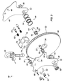
Fig. 3 shows an exploded view of the hay pulley. -
Fig. 4A shows a front cross-section of the hay pulley revealing the sheave, guide wheels, and top block when the hay pulley is in the operating condition. -
Fig. 4B shows a side cross-section of the hay pulley ofFig. 4A . -
Fig. 4C shows a detail of the side cross-section ofFig. 4B . -
Fig. 5A shows an elevational view of the hay pulley when the hay pulley is in the opened condition. -
Fig. 5B shows a side cross-section of the hay pulley ofFig. 5A . -
Fig. 5C shows a detail of the side cross-section ofFig. 5B . - A front view of a
hay pulley 10 according to the present disclosure is shown inFigs. 1A-1B , and a back view of thehay pulley 10 is shown inFigs. 2A-2B . Thehay pulley 10 can be used to guide a wireline for a wireline operation at a wellhead or for some other type of operation. Normally, thehay pulley 10 attaches to the wellhead below a sheave (not shown) at a stuffing box (not shown) on the wellhead. From this position, thehay pulley 10 guides the wireline between the stuffing box sheave and the wireline unit and reduces the lateral force that the wireline exerts on the wellhead. - The
hay pulley 10 has asheave 20, front andback plates 30/40, anaxle 50, and a support ortop block 70. Thesheave 20 can rotate on theaxle 50 connected between theplates 30/40. Thetop block 70 at the upper ends of theplates 30/40 connects to aclevis 90 used for hanging thepulley 10 during use. Thetop block 70 affixes to thefront plate 30 usingfasteners 33. However, theback plate 40 fits within achannel 76 in thetop block 70 and is held by internal components described below.Pins 37 connected to thefront plate 30 but not theback plate 30support guide wheels 35 near thesheave 20 for guiding a wireline (not shown) that can run in the sheave'sslot 22. -
Figs. 1A through 2B show thehay pulley 10 in an operating condition for guiding the wireline. This condition is also shown in the cross-sections ofFigs. 4A-4C . During operation, thesheave 20 supported on theaxle 50 has its periphery positioned near the bottom of thetop block 70, and theguide wheels 35 on thepins 37 fit partially into the sheave'sslot 22 to hold the wireline therein. - To facilitate rigging up the wireline in the sheave's
slot 22, however, the pulley'sback plate 40 can be moved away from thetop block 70, and thesheave 20 itself can also be moved away from thetop block 70 and guidewheels 35 so that additional space is provided for fitting the wireline in theslot 22. As explained in more detail below, a retainer removably connects theback plate 40 to thetop block 70. The retainer can selectively engage theback plate 40 and hold it to thetop block 70 for the operating condition, or the retainer can selectively disengage theback plate 40 so it can be moved to an opened condition. - As shown in
Figs. 1A-1B , the retainer has ahandle 84 at thetop block 70. Movement of thishandle 84 can selectively detachpins 80 that hold theback plate 40 in the top block'srear channel 76. When alock mechanism 86 is moved, for example, an operator can pull thehandle 84 outward from thefront plate 30, releasing thepins 80 from theback plate 40. Once freed, theback plate 40 can be rotated away from thetop block 70 so that thepulley 10 has an opened condition. - Such an opened condition is best shown in
Figs. 5A-5C . In the opened condition, theback plate 40 is freed from themovable pins 80 in thetop block 70 by the pulling of thehandle 84. Being freed, theback plate 40 can be moved and can turn theaxle 50. The rotatingaxle 50 then eccentrically shifts thesheave 20 downward away from thetop block 70 and theguide wheels 35, and the shiftedsheave 20 allows operators to install or remove the wireline in the sheave'sslot 22. All the while, thehay pulley 10 can remain hanging on theclevis 90. - Turning to
Fig. 3 showing additional details of thehay pulley 10, discussion now turns to how theback plate 40 is held and released from thetop block 70 and how thesheave 20 can shift away from theguide wheels 35 when theback plate 40 is moved out of the way. As shown, thetop block 70 fastens to thefront plate 30 usingvarious fasteners 33. Afastener 92 passes through anopening 72 in thetop block 70, and theclevis 90 fastens to thisfastener 92. - For the
axle 50, aneccentric bushing 52 fits on afirst end 62 of ashaft 60, and thebushing 52 positions in around opening 32 in thefront plate 30. A cotter pin type fastener andwasher assembly 56 then attaches to the shaft'sfirst end 62, holding it to theplate 30 but allowing it to turn in theopening 32. A bearingassembly 54 slips onto theshaft 60, and acentral opening 24 in thesheave 20 fits onto the bearingassembly 54 so thesheave 20 can rotate thereon. -
Guide wheels 35 fit ontopins 37, and ends of thesepins 37 connect toholes 36 in thefront plate 30. Theback plate 40 is then positioned on theaxle 50 by inserting the shaft'ssecond end 64 into acontoured opening 42 in theback plate 40 and fastening it to abolt 58 or the like. When an upper end of theback plate 40 is fit into the top block'schannel 70, distal ends of thepins 37 for theguide wheels 35 do not connect to theback plate 40. - Inside the
top block 70, pins 80 havingsprings 82 disposed thereon position into side holes 74 in thetop block 70. Proximal ends of thesepins 80 pass throughopenings 34 in thefront plate 30 and attach to the pullinghandle 84 outside theplate 30. Distal ends of themovable pins 80 fit intoopenings 44 in theback plate 40 so that thepins 80 can hold the end of theback plate 40 in the top block'schannel 76. Thelock 86 that connects to thefront plate 30 can be moved relative to thehandle 30 to selectively engage a shoulder on one of thepins 80 and to prevent thepins 80 from being moved by thehandle 84. - Returning to additional details of the
shaft 60, the shaft'ssecond end 64 has a detent that fits into the back plate'sopening 42 with a corresponding contour so theshaft 60 is prevented from rotating in theopening 42. However, rotation of theback plate 40 relative to thetop block 70 turns theshaft 60 of theaxle 50. At itsother end 62, theshaft 60 haskeys 63 next to a lip. Thesekeys 63 fit into acorresponding opening 53 in theeccentric bushing 52. Therefore, thebushing 52 turns with theshaft 60 and rotates in theround opening 32 in thefront plate 30 when turned. - When the
back plate 40 is unlocked from thetop block 70 and then rotated to the opened condition (e.g.,Fig. 5A ), theback plate 40 rotates theshaft 60 carrying thesheave 20. The rotatingshaft 60 turns theeccentric bushing 52 in the front plate'sround opening 32. As theshaft 60 turns eccentrically with thebushing 52, both theback plate 40 andsheave 20 drop clear of thetop block 70 until reaching the opened condition shown inFig. 5A . As a result, the rotated backplate 40 is moved out of the way of thetop block 70 allowing an operator to rig up the wireline on thesheave 20, and thesheave 20 dropped down from thetop block 70 gives the operator additional space to rig up the wireline in the sheave'sslot 22. - Although shown as having the separate
eccentric bushing 52 disposed on theshaft 60, it will be appreciated that an axle for the disclosedhay pulley 10 can have such an eccentric bushing integrally formed on the axle for fitting into a round opening of thefront plate 30. In addition, although theshaft 60 has thedetent end 64 fitting into the back plate's contouredopening 42 so that turning of theback plate 40 rotates theshaft 60, other types of connections could be used. - The foregoing description of preferred and other embodiments is not intended to limit or restrict the scope or applicability of the inventive concepts conceived of by the Applicants. In exchange for disclosing the inventive concepts contained herein, the Applicants desire all patent rights afforded by the appended claims. Therefore, it is intended that the appended claims include all modifications and alterations to the full extent that they come within the scope of the following claims or the equivalents thereof.
Claims (15)
- A wireline hay pulley, comprising:a support;first and second plates disposed adjacent one another, the first plate affixed to the support, the second plate removably connected to the support;an axle disposed between the first and second plates, the axle being eccentrically rotatable relative to the first plate and being rotatable by the second plate when disconnected from the support; anda sheave rotatably disposed on the axle between the first and second plates.
- The pulley of claim 1, wherein an end of the axle is eccentrically rotatable in a first opening in the first plate.
- The pulley of claim 1 or 2, wherein an end of the axle is fixedly connected to the second plate.
- The pulley of claim 1, 2 or 3, further comprising:a pin disposed on the first plate; anda wheel rotatably disposed on the pin adjacent a periphery of the sheave.
- The pulley of claim 2, 3 or 4, wherein the axle comprises:a shaft having a first end; andan eccentric bushing disposed on the first end and rotatable in the first opening in the first plate.
- The pulley of claim 3, 4 or 5, wherein the axle comprises a shaft having a detent in one end, the detent disposing in a contoured opening in the second plate.
- The pulley of any preceding claim, further comprising a bearing disposed on the axle and disposed in a central opening in the sheave.
- The pulley of any preceding claim, further comprising a retainer removably connecting the second plate to the support.
- The pulley of claim 8, wherein the retainer comprises at least one pin movably disposed in the support and having a distal end selectively engagable in at least one hole in the second plate.
- The pulley of claim 9, further comprising a handle connected to a proximal end of the at least one pin, the handle moving the at least one pin relative to the at least one hole.
- The pulley of claim 9 or 10, further comprising a lock disposed on the first plate, the lock being selectively engagable with the at least one pin.
- The pulley of any preceding claim, wherein the support defines a slot through which an edge of the second plate movably positions.
- The pulley of any one of claims 2 to 12, wherein the end of the axle eccentrically rotatable in the first opening of the first plate has a bushing disposed eccentrically to an axis of the axle and rotatably disposed in the first opening.
- The pulley of any one of claims 3 to 13, wherein the end of the axle fixedly connected to the second plate defines a detent, and wherein the second plate defines a second opening in which the detent of the second end fits.
- The pulley of claim 1, wherein the first plate has a round opening and the second plate has a slotted opening; and further comprising:a retainer removably connecting the second plate to the support;a shaft disposed between the first and second plates and having first and second ends, the second end having a detent disposed in the slotted opening of the second plate, the shaft being turnable by movement of the second plate;an eccentric bushing disposed on the first end of the shaft, the eccentric bushing rotatable with the shaft and rotatably disposed in the round opening of the first plate; andthe sheave rotatably disposed on the shaft between the first and second plates.
Applications Claiming Priority (1)
| Application Number | Priority Date | Filing Date | Title |
|---|---|---|---|
| US12/485,154 US8210502B2 (en) | 2009-06-16 | 2009-06-16 | Adjustable wireline sheave for hay pulley |
Publications (3)
| Publication Number | Publication Date |
|---|---|
| EP2278117A2 true EP2278117A2 (en) | 2011-01-26 |
| EP2278117A3 EP2278117A3 (en) | 2012-08-29 |
| EP2278117B1 EP2278117B1 (en) | 2013-12-25 |
Family
ID=42671914
Family Applications (1)
| Application Number | Title | Priority Date | Filing Date |
|---|---|---|---|
| EP10251088.0A Not-in-force EP2278117B1 (en) | 2009-06-16 | 2010-06-16 | Adjustable wireline sheave for wireline pulley |
Country Status (2)
| Country | Link |
|---|---|
| US (1) | US8210502B2 (en) |
| EP (1) | EP2278117B1 (en) |
Families Citing this family (11)
| Publication number | Priority date | Publication date | Assignee | Title |
|---|---|---|---|---|
| US9908749B2 (en) * | 2010-11-12 | 2018-03-06 | Harken, Inc. | Block |
| GB201108693D0 (en) * | 2011-05-24 | 2011-07-06 | Paradigm B V | Wireline apparatus |
| EP2703331B1 (en) * | 2012-09-03 | 2014-12-24 | Soletanche Freyssinet | Traction system using a multi-tendon cable with a deflection angle |
| US9764177B2 (en) * | 2015-03-31 | 2017-09-19 | Mad Dogg Athletics, Inc. | Physical fitness training system |
| US10689234B2 (en) * | 2018-03-09 | 2020-06-23 | X Development Llc | Pulley system with safety lock |
| CA185295S (en) * | 2018-06-15 | 2020-03-09 | Rotzler Holding Gmbh Co Kg | Pulley |
| USD920083S1 (en) * | 2019-11-04 | 2021-05-25 | Zhejiang Runva Mechanical & Electrical Co., Ltd | Pulley assembly |
| USD1029618S1 (en) * | 2021-08-13 | 2024-06-04 | Treemagineers Ltd | Pulley |
| USD1032338S1 (en) * | 2022-04-13 | 2024-06-25 | Zedel | Pulley |
| KR102634479B1 (en) * | 2023-04-27 | 2024-02-07 | 대한민국 | Wire automatic release pulley set apparatus used for forestry teansportation |
| US12330923B2 (en) | 2023-05-30 | 2025-06-17 | Spectrum Lab Holdings, Llc | Modular pulley block |
Family Cites Families (26)
| Publication number | Priority date | Publication date | Assignee | Title |
|---|---|---|---|---|
| US447199A (en) * | 1891-02-24 | Return pullet | ||
| US2283048A (en) * | 1940-06-10 | 1942-05-12 | Jr James Daviss Collett | Cleaning apparatus for wells |
| US3104094A (en) * | 1961-08-17 | 1963-09-17 | Rowan Drilling Company Inc | Wire line guide apparatus |
| US3171633A (en) * | 1962-08-01 | 1965-03-02 | Lebus Royalty Company | Swiveling single sheave |
| US3292908A (en) * | 1965-02-04 | 1966-12-20 | Washington Iron Works | Head mounting for main and haulback sheaves of a logging spar |
| US3385563A (en) * | 1966-10-17 | 1968-05-28 | Thomas W. Stinson Jr. | Block for supporting and guiding a line or the like |
| US3831676A (en) * | 1972-12-11 | 1974-08-27 | Otis Eng Corp | Stuffing box for wireline well apparatus |
| US4301995A (en) * | 1979-12-20 | 1981-11-24 | Niskin Shale J | Counter-balanced sheave |
| US4469171A (en) * | 1982-06-28 | 1984-09-04 | Paul Mine | Wireline guiding apparatus |
| US4480818A (en) * | 1982-09-02 | 1984-11-06 | Schlumberger Technology Corporation | Safety enhancement device for well-logging cable sheave wheels |
| IT8453082U1 (en) * | 1984-03-09 | 1985-09-09 | Riv Skf Officine Di Villar Perosa S P A | BELT TENSIONER GROUP SUITABLE FOR FITTING INTO A FLEXIBLE TRANSMISSION ESPECIALLY FOR A MOTOR VEHICLE. |
| DE3908818C1 (en) * | 1989-03-17 | 1990-07-26 | Skf Gmbh, 8720 Schweinfurt, De | Resiliently adjustable tensioning device |
| JP3526653B2 (en) * | 1995-05-16 | 2004-05-17 | 株式会社共立 | Portable work machine |
| US5645269A (en) * | 1995-06-07 | 1997-07-08 | Wireline Technologies | Sheave cable guarding and guiding device |
| US6386516B1 (en) * | 1998-02-27 | 2002-05-14 | National-Oilwell L.P. | Sheave block with retractable sheave guards |
| US6105939A (en) * | 1998-04-03 | 2000-08-22 | Wireline Technologies, Inc. | Stuffing box sheave assembly with retention pad |
| US6406101B2 (en) * | 2000-06-30 | 2002-06-18 | Morten Andre Lund | Shock absorbing bicycle wheel hub |
| US6536743B2 (en) * | 2001-05-09 | 2003-03-25 | Dynacon, Inc. | Fixed umbilical cable flotation docking head |
| US6481695B1 (en) * | 2001-07-13 | 2002-11-19 | The Crosby Group, Inc. | Snatch block hook bolt assembly |
| US6699149B1 (en) * | 2002-04-01 | 2004-03-02 | Brunswick Corporation | Idler pulley with a multiple position locating mechanism |
| BR0312556A (en) * | 2002-07-11 | 2005-10-18 | Gates Corp | Center locked crazy wheel tensioning mechanism |
| WO2006030186A1 (en) | 2004-09-14 | 2006-03-23 | Cromar Limited | Improved stuffing box |
| GB2433283A (en) | 2004-09-14 | 2007-06-20 | Cromar Ltd | Improved stuffing box |
| FR2903472B1 (en) * | 2006-07-07 | 2008-09-12 | Sercel Sa | ASSEMBLY ASSEMBLY PULLEY FOR REPLOYING / DEPLOYING A HETEROGENEOUS SYSTEM COMPRISING DIFFERENTLY ACCORDING TO TWO SUCCESSIVE STATES, AND CORRESPONDING DEVICE |
| CN101589209B (en) * | 2006-09-14 | 2014-06-11 | 有线技术有限公司 | Ring sheave |
| US7419138B1 (en) * | 2007-02-23 | 2008-09-02 | Cmc Rescue, Inc. | Self-camming pulley |
-
2009
- 2009-06-16 US US12/485,154 patent/US8210502B2/en not_active Expired - Fee Related
-
2010
- 2010-06-16 EP EP10251088.0A patent/EP2278117B1/en not_active Not-in-force
Non-Patent Citations (1)
| Title |
|---|
| None |
Also Published As
| Publication number | Publication date |
|---|---|
| EP2278117B1 (en) | 2013-12-25 |
| US20100317474A1 (en) | 2010-12-16 |
| EP2278117A3 (en) | 2012-08-29 |
| US8210502B2 (en) | 2012-07-03 |
Similar Documents
| Publication | Publication Date | Title |
|---|---|---|
| US8210502B2 (en) | Adjustable wireline sheave for hay pulley | |
| CA2612150C (en) | Security key tool for manhole access opening security device | |
| CA2612098C (en) | Security device for manhole access opening | |
| US9004212B2 (en) | Machine main body and operating machine provided with same | |
| JP3809954B2 (en) | Work vehicle with tilt floor | |
| JP5746753B2 (en) | Optical fiber wiring equipment | |
| EP2278118A2 (en) | Adjustable wireline sheave for stuffing box | |
| US20070256798A1 (en) | Garage door bracket assembly with slidable roller housing | |
| CN110312675B (en) | Forklift side door | |
| WO2020000012A1 (en) | A dipper assembly and parts thereof | |
| JPH09323892A (en) | Crane jib overhang, storage device and its extension and storage method | |
| DE102006014929B4 (en) | Locking device for a motorcycle side case and motorcycle case | |
| DE112006001841T5 (en) | Door locking device with safety switch | |
| JP2004084176A (en) | Blade device | |
| EP2526009B1 (en) | Locking system | |
| KR200453772Y1 (en) | Heavy Duty Doorstay | |
| JP2016130430A (en) | Skylight device for cab | |
| EP3269906A1 (en) | Door unlocking device for construction machine | |
| EP3912951A1 (en) | A pulley with a closure flap and a winch with the said pulley | |
| KR100446254B1 (en) | Coupler for tractor | |
| KR20060007743A (en) | Guide Roller Device | |
| US6097799A (en) | Pay phone box structure | |
| JP3115227B2 (en) | Opening and closing cover device for construction machinery | |
| CN219101009U (en) | Cab door lock and engineering machinery | |
| JP2884998B2 (en) | Combine grain storage equipment |
Legal Events
| Date | Code | Title | Description |
|---|---|---|---|
| PUAI | Public reference made under article 153(3) epc to a published international application that has entered the european phase |
Free format text: ORIGINAL CODE: 0009012 |
|
| 17P | Request for examination filed |
Effective date: 20100622 |
|
| AK | Designated contracting states |
Kind code of ref document: A2 Designated state(s): AL AT BE BG CH CY CZ DE DK EE ES FI FR GB GR HR HU IE IS IT LI LT LU LV MC MK MT NL NO PL PT RO SE SI SK SM TR |
|
| AX | Request for extension of the european patent |
Extension state: BA ME RS |
|
| PUAL | Search report despatched |
Free format text: ORIGINAL CODE: 0009013 |
|
| AK | Designated contracting states |
Kind code of ref document: A3 Designated state(s): AL AT BE BG CH CY CZ DE DK EE ES FI FR GB GR HR HU IE IS IT LI LT LU LV MC MK MT NL NO PL PT RO SE SI SK SM TR |
|
| AX | Request for extension of the european patent |
Extension state: BA ME RS |
|
| RIC1 | Information provided on ipc code assigned before grant |
Ipc: F16H 55/52 20060101ALI20120725BHEP Ipc: E21B 33/072 20060101AFI20120725BHEP |
|
| REG | Reference to a national code |
Ref country code: DE Ref legal event code: R079 Ref document number: 602010012638 Country of ref document: DE Free format text: PREVIOUS MAIN CLASS: E21B0019220000 Ipc: E21B0033072000 |
|
| RIC1 | Information provided on ipc code assigned before grant |
Ipc: E21B 33/072 20060101AFI20130319BHEP Ipc: F16H 55/52 20060101ALI20130319BHEP |
|
| GRAP | Despatch of communication of intention to grant a patent |
Free format text: ORIGINAL CODE: EPIDOSNIGR1 |
|
| INTG | Intention to grant announced |
Effective date: 20130805 |
|
| GRAS | Grant fee paid |
Free format text: ORIGINAL CODE: EPIDOSNIGR3 |
|
| GRAA | (expected) grant |
Free format text: ORIGINAL CODE: 0009210 |
|
| AK | Designated contracting states |
Kind code of ref document: B1 Designated state(s): AL AT BE BG CH CY CZ DE DK EE ES FI FR GB GR HR HU IE IS IT LI LT LU LV MC MK MT NL NO PL PT RO SE SI SK SM TR |
|
| REG | Reference to a national code |
Ref country code: GB Ref legal event code: FG4D |
|
| REG | Reference to a national code |
Ref country code: CH Ref legal event code: EP |
|
| REG | Reference to a national code |
Ref country code: AT Ref legal event code: REF Ref document number: 646772 Country of ref document: AT Kind code of ref document: T Effective date: 20140115 |
|
| REG | Reference to a national code |
Ref country code: IE Ref legal event code: FG4D |
|
| REG | Reference to a national code |
Ref country code: DE Ref legal event code: R096 Ref document number: 602010012638 Country of ref document: DE Effective date: 20140213 |
|
| PG25 | Lapsed in a contracting state [announced via postgrant information from national office to epo] |
Ref country code: HR Free format text: LAPSE BECAUSE OF FAILURE TO SUBMIT A TRANSLATION OF THE DESCRIPTION OR TO PAY THE FEE WITHIN THE PRESCRIBED TIME-LIMIT Effective date: 20131225 Ref country code: SE Free format text: LAPSE BECAUSE OF FAILURE TO SUBMIT A TRANSLATION OF THE DESCRIPTION OR TO PAY THE FEE WITHIN THE PRESCRIBED TIME-LIMIT Effective date: 20131225 Ref country code: FI Free format text: LAPSE BECAUSE OF FAILURE TO SUBMIT A TRANSLATION OF THE DESCRIPTION OR TO PAY THE FEE WITHIN THE PRESCRIBED TIME-LIMIT Effective date: 20131225 Ref country code: LT Free format text: LAPSE BECAUSE OF FAILURE TO SUBMIT A TRANSLATION OF THE DESCRIPTION OR TO PAY THE FEE WITHIN THE PRESCRIBED TIME-LIMIT Effective date: 20131225 |
|
| REG | Reference to a national code |
Ref country code: NL Ref legal event code: VDEP Effective date: 20131225 |
|
| REG | Reference to a national code |
Ref country code: NO Ref legal event code: T2 Effective date: 20131225 |
|
| REG | Reference to a national code |
Ref country code: AT Ref legal event code: MK05 Ref document number: 646772 Country of ref document: AT Kind code of ref document: T Effective date: 20131225 |
|
| REG | Reference to a national code |
Ref country code: LT Ref legal event code: MG4D |
|
| PG25 | Lapsed in a contracting state [announced via postgrant information from national office to epo] |
Ref country code: LV Free format text: LAPSE BECAUSE OF FAILURE TO SUBMIT A TRANSLATION OF THE DESCRIPTION OR TO PAY THE FEE WITHIN THE PRESCRIBED TIME-LIMIT Effective date: 20131225 |
|
| PG25 | Lapsed in a contracting state [announced via postgrant information from national office to epo] |
Ref country code: EE Free format text: LAPSE BECAUSE OF FAILURE TO SUBMIT A TRANSLATION OF THE DESCRIPTION OR TO PAY THE FEE WITHIN THE PRESCRIBED TIME-LIMIT Effective date: 20131225 Ref country code: IS Free format text: LAPSE BECAUSE OF FAILURE TO SUBMIT A TRANSLATION OF THE DESCRIPTION OR TO PAY THE FEE WITHIN THE PRESCRIBED TIME-LIMIT Effective date: 20140425 Ref country code: BE Free format text: LAPSE BECAUSE OF FAILURE TO SUBMIT A TRANSLATION OF THE DESCRIPTION OR TO PAY THE FEE WITHIN THE PRESCRIBED TIME-LIMIT Effective date: 20131225 |
|
| PG25 | Lapsed in a contracting state [announced via postgrant information from national office to epo] |
Ref country code: ES Free format text: LAPSE BECAUSE OF FAILURE TO SUBMIT A TRANSLATION OF THE DESCRIPTION OR TO PAY THE FEE WITHIN THE PRESCRIBED TIME-LIMIT Effective date: 20131225 Ref country code: SK Free format text: LAPSE BECAUSE OF FAILURE TO SUBMIT A TRANSLATION OF THE DESCRIPTION OR TO PAY THE FEE WITHIN THE PRESCRIBED TIME-LIMIT Effective date: 20131225 Ref country code: AT Free format text: LAPSE BECAUSE OF FAILURE TO SUBMIT A TRANSLATION OF THE DESCRIPTION OR TO PAY THE FEE WITHIN THE PRESCRIBED TIME-LIMIT Effective date: 20131225 Ref country code: NL Free format text: LAPSE BECAUSE OF FAILURE TO SUBMIT A TRANSLATION OF THE DESCRIPTION OR TO PAY THE FEE WITHIN THE PRESCRIBED TIME-LIMIT Effective date: 20131225 Ref country code: CZ Free format text: LAPSE BECAUSE OF FAILURE TO SUBMIT A TRANSLATION OF THE DESCRIPTION OR TO PAY THE FEE WITHIN THE PRESCRIBED TIME-LIMIT Effective date: 20131225 Ref country code: CY Free format text: LAPSE BECAUSE OF FAILURE TO SUBMIT A TRANSLATION OF THE DESCRIPTION OR TO PAY THE FEE WITHIN THE PRESCRIBED TIME-LIMIT Effective date: 20131225 Ref country code: RO Free format text: LAPSE BECAUSE OF FAILURE TO SUBMIT A TRANSLATION OF THE DESCRIPTION OR TO PAY THE FEE WITHIN THE PRESCRIBED TIME-LIMIT Effective date: 20131225 Ref country code: PT Free format text: LAPSE BECAUSE OF FAILURE TO SUBMIT A TRANSLATION OF THE DESCRIPTION OR TO PAY THE FEE WITHIN THE PRESCRIBED TIME-LIMIT Effective date: 20140428 |
|
| REG | Reference to a national code |
Ref country code: DE Ref legal event code: R097 Ref document number: 602010012638 Country of ref document: DE |
|
| PG25 | Lapsed in a contracting state [announced via postgrant information from national office to epo] |
Ref country code: DK Free format text: LAPSE BECAUSE OF FAILURE TO SUBMIT A TRANSLATION OF THE DESCRIPTION OR TO PAY THE FEE WITHIN THE PRESCRIBED TIME-LIMIT Effective date: 20131225 |
|
| PLBE | No opposition filed within time limit |
Free format text: ORIGINAL CODE: 0009261 |
|
| STAA | Information on the status of an ep patent application or granted ep patent |
Free format text: STATUS: NO OPPOSITION FILED WITHIN TIME LIMIT |
|
| PG25 | Lapsed in a contracting state [announced via postgrant information from national office to epo] |
Ref country code: PL Free format text: LAPSE BECAUSE OF FAILURE TO SUBMIT A TRANSLATION OF THE DESCRIPTION OR TO PAY THE FEE WITHIN THE PRESCRIBED TIME-LIMIT Effective date: 20131225 |
|
| 26N | No opposition filed |
Effective date: 20140926 |
|
| REG | Reference to a national code |
Ref country code: DE Ref legal event code: R119 Ref document number: 602010012638 Country of ref document: DE |
|
| REG | Reference to a national code |
Ref country code: DE Ref legal event code: R097 Ref document number: 602010012638 Country of ref document: DE Effective date: 20140926 |
|
| PG25 | Lapsed in a contracting state [announced via postgrant information from national office to epo] |
Ref country code: MC Free format text: LAPSE BECAUSE OF FAILURE TO SUBMIT A TRANSLATION OF THE DESCRIPTION OR TO PAY THE FEE WITHIN THE PRESCRIBED TIME-LIMIT Effective date: 20131225 Ref country code: LU Free format text: LAPSE BECAUSE OF FAILURE TO SUBMIT A TRANSLATION OF THE DESCRIPTION OR TO PAY THE FEE WITHIN THE PRESCRIBED TIME-LIMIT Effective date: 20140616 |
|
| REG | Reference to a national code |
Ref country code: CH Ref legal event code: PL |
|
| REG | Reference to a national code |
Ref country code: IE Ref legal event code: MM4A |
|
| REG | Reference to a national code |
Ref country code: DE Ref legal event code: R119 Ref document number: 602010012638 Country of ref document: DE Effective date: 20150101 |
|
| REG | Reference to a national code |
Ref country code: FR Ref legal event code: ST Effective date: 20150227 |
|
| PG25 | Lapsed in a contracting state [announced via postgrant information from national office to epo] |
Ref country code: CH Free format text: LAPSE BECAUSE OF NON-PAYMENT OF DUE FEES Effective date: 20140630 Ref country code: DE Free format text: LAPSE BECAUSE OF NON-PAYMENT OF DUE FEES Effective date: 20150101 Ref country code: IE Free format text: LAPSE BECAUSE OF NON-PAYMENT OF DUE FEES Effective date: 20140616 Ref country code: LI Free format text: LAPSE BECAUSE OF NON-PAYMENT OF DUE FEES Effective date: 20140630 |
|
| PG25 | Lapsed in a contracting state [announced via postgrant information from national office to epo] |
Ref country code: FR Free format text: LAPSE BECAUSE OF NON-PAYMENT OF DUE FEES Effective date: 20140630 Ref country code: SI Free format text: LAPSE BECAUSE OF FAILURE TO SUBMIT A TRANSLATION OF THE DESCRIPTION OR TO PAY THE FEE WITHIN THE PRESCRIBED TIME-LIMIT Effective date: 20131225 |
|
| REG | Reference to a national code |
Ref country code: GB Ref legal event code: 732E Free format text: REGISTERED BETWEEN 20151029 AND 20151104 |
|
| PG25 | Lapsed in a contracting state [announced via postgrant information from national office to epo] |
Ref country code: MT Free format text: LAPSE BECAUSE OF FAILURE TO SUBMIT A TRANSLATION OF THE DESCRIPTION OR TO PAY THE FEE WITHIN THE PRESCRIBED TIME-LIMIT Effective date: 20131225 |
|
| PG25 | Lapsed in a contracting state [announced via postgrant information from national office to epo] |
Ref country code: SM Free format text: LAPSE BECAUSE OF FAILURE TO SUBMIT A TRANSLATION OF THE DESCRIPTION OR TO PAY THE FEE WITHIN THE PRESCRIBED TIME-LIMIT Effective date: 20131225 |
|
| PG25 | Lapsed in a contracting state [announced via postgrant information from national office to epo] |
Ref country code: BG Free format text: LAPSE BECAUSE OF FAILURE TO SUBMIT A TRANSLATION OF THE DESCRIPTION OR TO PAY THE FEE WITHIN THE PRESCRIBED TIME-LIMIT Effective date: 20131225 Ref country code: GR Free format text: LAPSE BECAUSE OF FAILURE TO SUBMIT A TRANSLATION OF THE DESCRIPTION OR TO PAY THE FEE WITHIN THE PRESCRIBED TIME-LIMIT Effective date: 20140326 Ref country code: IT Free format text: LAPSE BECAUSE OF FAILURE TO SUBMIT A TRANSLATION OF THE DESCRIPTION OR TO PAY THE FEE WITHIN THE PRESCRIBED TIME-LIMIT Effective date: 20131225 |
|
| PG25 | Lapsed in a contracting state [announced via postgrant information from national office to epo] |
Ref country code: TR Free format text: LAPSE BECAUSE OF FAILURE TO SUBMIT A TRANSLATION OF THE DESCRIPTION OR TO PAY THE FEE WITHIN THE PRESCRIBED TIME-LIMIT Effective date: 20131225 Ref country code: HU Free format text: LAPSE BECAUSE OF FAILURE TO SUBMIT A TRANSLATION OF THE DESCRIPTION OR TO PAY THE FEE WITHIN THE PRESCRIBED TIME-LIMIT; INVALID AB INITIO Effective date: 20100616 |
|
| PG25 | Lapsed in a contracting state [announced via postgrant information from national office to epo] |
Ref country code: MK Free format text: LAPSE BECAUSE OF FAILURE TO SUBMIT A TRANSLATION OF THE DESCRIPTION OR TO PAY THE FEE WITHIN THE PRESCRIBED TIME-LIMIT Effective date: 20131225 |
|
| PG25 | Lapsed in a contracting state [announced via postgrant information from national office to epo] |
Ref country code: AL Free format text: LAPSE BECAUSE OF FAILURE TO SUBMIT A TRANSLATION OF THE DESCRIPTION OR TO PAY THE FEE WITHIN THE PRESCRIBED TIME-LIMIT Effective date: 20131225 |
|
| REG | Reference to a national code |
Ref country code: NO Ref legal event code: CHAD Owner name: WEATHERFORD TECHNOLOGY HOLDINGS, US Ref country code: NO Ref legal event code: CREP Representative=s name: BRYN AARFLOT AS, STORTINGSGATA 8, 0161 OSLO, NORGE |
|
| REG | Reference to a national code |
Ref country code: NO Ref legal event code: PLED Effective date: 20200525 |
|
| PGFP | Annual fee paid to national office [announced via postgrant information from national office to epo] |
Ref country code: NO Payment date: 20200609 Year of fee payment: 11 |
|
| PGFP | Annual fee paid to national office [announced via postgrant information from national office to epo] |
Ref country code: GB Payment date: 20200401 Year of fee payment: 11 |
|
| REG | Reference to a national code |
Ref country code: GB Ref legal event code: 732E Free format text: REGISTERED BETWEEN 20200813 AND 20200819 |
|
| REG | Reference to a national code |
Ref country code: GB Ref legal event code: 732E Free format text: REGISTERED BETWEEN 20201126 AND 20201202 |
|
| REG | Reference to a national code |
Ref country code: GB Ref legal event code: 732E Free format text: REGISTERED BETWEEN 20210225 AND 20210303 |
|
| REG | Reference to a national code |
Ref country code: NO Ref legal event code: MMEP |
|
| GBPC | Gb: european patent ceased through non-payment of renewal fee |
Effective date: 20210616 |
|
| PG25 | Lapsed in a contracting state [announced via postgrant information from national office to epo] |
Ref country code: GB Free format text: LAPSE BECAUSE OF NON-PAYMENT OF DUE FEES Effective date: 20210616 |
|
| PG25 | Lapsed in a contracting state [announced via postgrant information from national office to epo] |
Ref country code: NO Free format text: LAPSE BECAUSE OF NON-PAYMENT OF DUE FEES Effective date: 20210630 |