EP2277778A2 - Systèmes de gestion de la santé d'un véhicule et procédés avec des indicateurs de diagnostic prédits - Google Patents
Systèmes de gestion de la santé d'un véhicule et procédés avec des indicateurs de diagnostic prédits Download PDFInfo
- Publication number
- EP2277778A2 EP2277778A2 EP10161536A EP10161536A EP2277778A2 EP 2277778 A2 EP2277778 A2 EP 2277778A2 EP 10161536 A EP10161536 A EP 10161536A EP 10161536 A EP10161536 A EP 10161536A EP 2277778 A2 EP2277778 A2 EP 2277778A2
- Authority
- EP
- European Patent Office
- Prior art keywords
- failure mode
- diagnostic
- module
- prognostic
- health
- Prior art date
- Legal status (The legal status is an assumption and is not a legal conclusion. Google has not performed a legal analysis and makes no representation as to the accuracy of the status listed.)
- Withdrawn
Links
- 230000036541 health Effects 0.000 title claims abstract description 59
- 238000000034 method Methods 0.000 title description 16
- 238000012544 monitoring process Methods 0.000 claims abstract description 32
- 239000013598 vector Substances 0.000 claims abstract description 17
- 230000006866 deterioration Effects 0.000 claims description 4
- 230000009471 action Effects 0.000 claims description 3
- 230000000007 visual effect Effects 0.000 claims description 2
- 238000007726 management method Methods 0.000 description 29
- 238000010586 diagram Methods 0.000 description 4
- 230000006870 function Effects 0.000 description 4
- 238000001514 detection method Methods 0.000 description 3
- 230000008569 process Effects 0.000 description 3
- 238000013459 approach Methods 0.000 description 2
- 238000004891 communication Methods 0.000 description 2
- 238000013461 design Methods 0.000 description 2
- 230000003287 optical effect Effects 0.000 description 2
- 238000004393 prognosis Methods 0.000 description 2
- 206010000210 abortion Diseases 0.000 description 1
- 238000009825 accumulation Methods 0.000 description 1
- 238000013528 artificial neural network Methods 0.000 description 1
- 230000008901 benefit Effects 0.000 description 1
- 230000005540 biological transmission Effects 0.000 description 1
- 239000000969 carrier Substances 0.000 description 1
- 230000001934 delay Effects 0.000 description 1
- 238000011161 development Methods 0.000 description 1
- 238000003745 diagnosis Methods 0.000 description 1
- 230000007613 environmental effect Effects 0.000 description 1
- 230000003993 interaction Effects 0.000 description 1
- 239000004973 liquid crystal related substance Substances 0.000 description 1
- 238000012423 maintenance Methods 0.000 description 1
- 239000000463 material Substances 0.000 description 1
- 230000007246 mechanism Effects 0.000 description 1
- 238000012986 modification Methods 0.000 description 1
- 230000004048 modification Effects 0.000 description 1
- 238000012545 processing Methods 0.000 description 1
- 230000000246 remedial effect Effects 0.000 description 1
- 230000008439 repair process Effects 0.000 description 1
- 238000011160 research Methods 0.000 description 1
- 230000003068 static effect Effects 0.000 description 1
- 238000012731 temporal analysis Methods 0.000 description 1
- 238000000700 time series analysis Methods 0.000 description 1
Images
Classifications
-
- G—PHYSICS
- G05—CONTROLLING; REGULATING
- G05B—CONTROL OR REGULATING SYSTEMS IN GENERAL; FUNCTIONAL ELEMENTS OF SUCH SYSTEMS; MONITORING OR TESTING ARRANGEMENTS FOR SUCH SYSTEMS OR ELEMENTS
- G05B23/00—Testing or monitoring of control systems or parts thereof
- G05B23/02—Electric testing or monitoring
- G05B23/0205—Electric testing or monitoring by means of a monitoring system capable of detecting and responding to faults
- G05B23/0218—Electric testing or monitoring by means of a monitoring system capable of detecting and responding to faults characterised by the fault detection method dealing with either existing or incipient faults
- G05B23/0243—Electric testing or monitoring by means of a monitoring system capable of detecting and responding to faults characterised by the fault detection method dealing with either existing or incipient faults model based detection method, e.g. first-principles knowledge model
- G05B23/0245—Electric testing or monitoring by means of a monitoring system capable of detecting and responding to faults characterised by the fault detection method dealing with either existing or incipient faults model based detection method, e.g. first-principles knowledge model based on a qualitative model, e.g. rule based; if-then decisions
- G05B23/0248—Causal models, e.g. fault tree; digraphs; qualitative physics
-
- G—PHYSICS
- G05—CONTROLLING; REGULATING
- G05B—CONTROL OR REGULATING SYSTEMS IN GENERAL; FUNCTIONAL ELEMENTS OF SUCH SYSTEMS; MONITORING OR TESTING ARRANGEMENTS FOR SUCH SYSTEMS OR ELEMENTS
- G05B23/00—Testing or monitoring of control systems or parts thereof
- G05B23/02—Electric testing or monitoring
- G05B23/0205—Electric testing or monitoring by means of a monitoring system capable of detecting and responding to faults
- G05B23/0259—Electric testing or monitoring by means of a monitoring system capable of detecting and responding to faults characterized by the response to fault detection
- G05B23/0283—Predictive maintenance, e.g. involving the monitoring of a system and, based on the monitoring results, taking decisions on the maintenance schedule of the monitored system; Estimating remaining useful life [RUL]
Definitions
- the present invention relates to health management systems and methods, and more particularly relates to health management systems and methods with prognostic and diagnostic indictors.
- Health management systems are often used to monitor various health characteristics of vehicle systems.
- prognostic and diagnostic indictors in an effort to predict faults in the vehicle system.
- the complexities of modem electronic and mechanical systems have led to increasing needs for more sophisticated health systems.
- Information about potential faults enables such faults to be addressed before issues arise. In general, this information may provide support for an operator or other individual for use in making decisions regarding future maintenance, operation, or use of the system, and/or for use in making other decisions.
- prognosis and fault detection are of particular importance.
- prognosis and diagnostic fault detection can detect potential faults such that they can be addressed before they result in serious system issues and possible in-flight shutdowns, take-off aborts, delays or cancellations.
- Aircraft systems to be monitored include various types of operational systems comprising subsystems, components and sensors. Designers are continually attempting to provide health management systems and methods with improved fault detection and prediction, particularly in a more cost effective and simpler manner.
- a system for monitoring the health of a component includes a memory configured to store a health management system for evaluating the health of the component.
- the health management system includes a first prognostic module, a first diagnostic module, a first failure mode module, and a first functional module.
- a processor is coupled to the memory and configured to retrieve the health management system from the memory; receive a first prognostic indicator associated with the health of the component; determine a first predicted diagnostic indicator based on the prognostic indicator with the prognostic module; determine a first failure mode probability based on the first predicted diagnostic indicator with the diagnostic module; determine a first failure mode vector based on the first failure mode probability with the failure mode module; generate a first functional output based on the first failure mode vector with the first functional mode module; and provide the first functional output to an operator.
- a system for monitoring the health of a component.
- the system includes a memory configured to store a health management system; and a processor coupled to the memory.
- the system is configured to retrieve the health management system from the memory; receive a first observed diagnostic indictor associated with the health of the component; receive a first predicted diagnostic indictor associated with the health of the component; determine a first failure mode probability associated with the first observed diagnostic indicator and the first predicted diagnostic indicator; generate a first functional output based on the first failure mode probability; and provide the first functional output to an operator.
- a method for monitoring the health of a component. The method includes the steps of receiving first predicted diagnostic indictors associated with the health of the component; determining first failure mode probabilities based on the first predicted diagnostic indictors; generating a functional output based on the first failure mode probabilities; and providing the functional output to an operator.
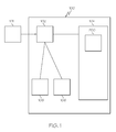
- FIG. 1 is a system diagram of a monitoring system in accordance with an exemplary embodiment
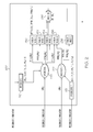
- FIG. 2 is a functional block diagram of a heath management system of the system of FIG. 1 in accordance with an exemplary embodiment
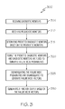
- FIG. 3 is a flowchart of a process for evaluating the health of a unit in accordance with an exemplary embodiment of the present invention.
- exemplary embodiments discussed herein include a health management system of a monitoring system that monitors the health of a component such as a line replaceable unit of an aircraft.
- the health management system receives prognostic indictors from the line replaceable unit and identifies predicted diagnostic indictors based on the prognostic indictors.
- the health management system subsequently determines a failure mode and/or functional output based on the predicted diagnostic indictors.
- FIG. 1 is a system diagram of a monitoring system 100 in accordance with an exemplary embodiment.
- the monitoring system 100 is an aircraft monitoring system 100, although many of the embodiments discussed herein are also applicable to more general vehicle systems as well as other types of systems.
- the monitoring system 100 forms part of an aircraft system and monitors the health of a line replaceable unit 101.
- the health management system 200 can be associated with any number of line replaceable units or other types of units.
- the monitoring system 100 includes a processor 102, a memory 104, an interface 106, and a storage device 108.
- the processor 102 performs the computation and control functions of the monitoring system 100 or portions thereof, and may comprise any type of processor or multiple processors, single integrated circuits such as a microprocessor, or any suitable number of integrated circuit devices and/or circuit boards working in cooperation to accomplish the functions of a processing unit.
- the processor 102 executes a health management system 200, which can include one or more programs stored within the memory 104 and, as such, controls the operation of the monitoring system 100.
- the processor 102 receives the diagnostic indictors and prognostic indictors from the line replaceable unit 101 and executes the health management system 200 to generate failure modes and functional outputs associated with health of the line replaceable unit 101.
- the monitoring system 100 may also differ from the embodiment depicted in FIG. 1 , for example in that the monitoring system 100 may be coupled to or may otherwise utilize one or more remote computer systems and/or other control systems.
- the memory 104 stores the health management system 200, which may include a program to be executed.
- the memory 104 can be any type of suitable memory. This would include the various types of dynamic random access memory (DRAM) such as SDRAM, the various types of static RAM (SRAM), and the various types of non-volatile memory (PROM, EPROM, and flash).
- DRAM dynamic random access memory
- SRAM static RAM
- PROM EPROM
- flash non-volatile memory
- the memory 104 may be a single type of memory component or may be composed of many different types of memory components.
- the memory 104 and the processor 102 may be distributed across several different computers that collectively comprise the monitoring system 100. For example, a portion of the memory 104 may reside on a computer within a particular apparatus or process, and another portion may reside on a remote computer.
- the interface 106 allows communication to and from the monitoring system 100, for example to and from a system operator and/or another computer system.
- the interface 106 can be implemented using any suitable method and apparatus.
- the interface 106 can include one or more network interfaces to communicate within or to other systems or components, and/or one or more terminal interfaces to communicate with technicians.
- the interface 106 includes a visual display.
- the interface 106 may include a liquid crystal (LCD) display, another type of computer display, and/or any one of a number of different types of displays, user interfaces, and/or presentation layers in which decision support output can be presented to such a user of the monitoring system 100 of FIG. 1 and/or an operator of the vehicle for which the monitoring system 100 and the health management system 200 is being implemented or used.
- LCD liquid crystal
- the storage device 108 can be any suitable type of storage apparatus, including direct access storage devices such as hard disk drives, flash systems, floppy disk drives, optical disk drives, and other computer readable media.
- the storage device 108 is a program product stored on a signal bearing medium from which memory 104 can receive and store a program, for example, a program associated with the health management system 200.
- Examples of signal bearing media include: recordable media such as floppy disks, hard drives, memory cards and optical disks, and transmission media such as digital and analog communication links.
- FIG. 2 is a functional block diagram of a heath management system 200 of the monitoring system 100 of FIG. 1 in accordance with an exemplary embodiment. Reference is additionally made to FIG. 1 . As noted above, a portion or all of the health management system 200 may be stored in the memory 104 of the monitoring system 100 discussed above and executed by the processor 102.
- the health management system 200 includes a number of models, data structures or algorithms that are referred to herein as "modules," and FIG. 2 describes the hierarchy and relationships between these modules. As will be discussed in further detail below, the health management system 200 includes one or more prognostic indictor modules 210, 212, one or more diagnostic indictor modules 220, 222, one or more failure mode modules 230, 232, 234, 236, 238, and one or more functional modules 240. Although FIG. 2 only shows two prognostic indictor modules 210, 212, two diagnostic indictor modules 220, 222, five failure mode modules 230, 232, 234, 236, 238, and one functional module 240, any number or combination of these modules and/or additional modules may be provided.
- the diagnostic indictor modules 220, 222 receive diagnostic indictors from the line replaceable unit 101 via the processor 102.
- each diagnostic indictor is generally a binary state that indicts or exonerates a belief in a particular failure mode at the present time.
- the failure mode generally refers to the various ways in which a component of the line replaceable unit 101 can fail.
- the diagnostic indictors can have more than two states.
- the diagnostic indictors may also be referred to as current or observed diagnostic indictors since they represent diagnostic indictors from the line replaceable unit 101 in real time.
- the diagnostic indictor modules 220, 222 each generally represent one or more models, algorithms or data structures executed by the processor 102 to associate the diagnostic indictors with the appropriate failure mode module 230, 232, 234, 236, 238.
- the processor 102 processes the first diagnostic indicators with the first diagnostic indictor module 220 and the second diagnostic indicators with the second diagnostic indictor module 222.
- diagnostic indictors of the first diagnostic module 220 are associated with the first, second, third, and fourth failure mode modules 230, 232, 234, 236.
- the first diagnostic indictors may indicate one of four failure modes.
- the second diagnostic indictors of the second diagnostic indictor module 222 are associated with the third, fourth, and fifth failure mode indictor modules 234, 236, 238.
- the failure mode probability may be represented as P(FMx
- M 1 ) refers to the probability of the second failure mode given the first diagnostic indictor.
- the health management system 200 further includes prognostic indictor modules 210, 212, including a first prognostic indictor module 210 and a second prognostic indictor module 212.
- the monitoring system 100 receives prognostic indictors from the line replaceable unit 101.
- the prognostic indictors are associated with predicted diagnostic indictors using the prognostic indictor modules 210, 212 to produce predicted diagnostic indictors over time.
- the predicted diagnostic indictors may be in the form of ⁇ DM 1 , (P 0 ,T 0 ), (P 1 ,T 1 ),... (P n ,T n ) ⁇ , which represents the probability of the first diagnostic indictor at time 0, the probability of the first diagnostic indictor at time 1, and so on.
- the first prognostic indictor module 210 is associated with the first diagnostic indictor module 220 and determines first predicted diagnostic indictors.
- the second prognostic indictor module 212 is associated with the second diagnostic indictor module 222 and determines second predicted diagnostic indictors.
- the monitoring system 100 may receive parametric indictors from which the predicted diagnostic indictors may be identified.
- the diagnostic indictor modules 220, 222 further determine the failure mode probabilities with the predicted diagnostic indictors. This enables consideration of the prognostic indictors using the code and/or algorithms associated with the diagnostic indictors. In many conventional health management systems, the prognostic indictors are used to directly predict failure modes and require specific algorithms for this purpose. The conventional mechanism of using diagnostic indictors and prognostic indictors to respectively diagnose and predict failure modes may be both time consuming and expensive. The approach described here allows the failure characteristics of the monitored equipment to be modeled, allowing generalized algorithms to draw conclusions based on received diagnostic and prognostic evidence.
- Each failure mode module 230, 232, 234, 236, 238 is typically one or more models, algorithms or data structures associated with a failure mode.
- the failure mode modules 230, 232, 234, 236, 238 may collectively represent a failure mode ambiguity group in which the failure modes probabilities from the various diagnostic indictor modules 220, 222 serve to disambiguate the failure modes.
- the failure mode modules 230, 232, 234, 236, 238 are used to fuse the failure mode probabilities determined with the diagnostic monitor modules 220, 222 to identify predicted failure mode vectors.
- the failure mode vectors of the first failure mode indictor 230 can be represented as ⁇ (P(FM 1 ,T 0 ), (P(FM 1 ,T 1 ),...
- failure mode vectors provide the current health of the line replaceable unit 101 and predict future deterioration.
- the confidence of the accuracy of failure mode vectors may be increased because the conclusion was reached using different data and knowledge sources.
- failure diagnosis A variety of methods may be used for failure diagnosis. They include such methods as time series analysis, fuzzy logic methods, neural networks, case-based reasoning, probability reasoning, and a combination of the above methods.
- the failure mode modules 230, 232, 234, 236, 238 may also use other system variables to determine the failure mode probabilities, including environmental conditions and/or past or present operational variables.
- the health monitoring system 200 may determine failure mode probabilities without observed diagnostic indicators, i.e., relying primarily on predicted diagnostic indicators identified from the prognostic indicators.
- a functional module 240 identifies a functional output based on the failure mode probability vectors.
- the functional module 240 is typically one or more algorithms or data structures that associate one or more failure mode vectors with one or more functional outputs.
- the functional output may be provided to an operator, for example, via the interface 106, or stored in the memory 104 or storage device 108.
- the functional output may be an assessment of the design function of one or more components of the line replaceable unit 101, and as such, may include the functional availability.
- the functional availability may indicate a current assessment or a future state assessment.
- the functional output may trigger remedial action to address any failure in the line replaceable unit 101.
- the functional output typically includes an identification of the various functions likely affected by the failure mode.
- the functional output can be used to determine a repair window in which corrective action should be taken in anticipation of predicted future deterioration and/or appropriate corrective action.
- the functional output can be used to determine when deterioration is predicted to justify removal or shut-down of the line replaceable unit 101.
- FIG. 3 is a flowchart of a health management method 300 in accordance with an exemplary embodiment.
- the health management method 300 can be implemented, for example, with the monitoring system 100 and health management system 200 of FIGS. 1 and 2 , which are additionally referred to below.
- the method 300 begins with a first step 305 of receiving diagnostic indictors from the system or component to be evaluated, such as the line replaceable unit 101 of FIG. 1 .
- a second step 310 prognostic indictors are received, and in a third step 315, predicted diagnostic indictors are identified or determined based on the prognostic indictors.
- the second step occurs prior to, after, or simultaneously with the first step.
- the predicted diagnostic indictors and diagnostic indictors are fused to identify failure mode probabilities.
- the failure mode probabilities are not determined using observed diagnostic indicators.
- the failure mode probabilities are disambiguated to determine failure mode vectors or fused failure mode probabilities over time.
- a functional output is generated based on the failure mode vectors.
- the aircraft monitoring system 100 can be used in connection with an aircraft or a fleet of aircraft. In another embodiment, the monitoring system 100 can be used in connection with an automobile or a fleet of automobiles. In other embodiments, the monitoring system 100 can be used in connection with various other different types of vehicles or vehicle systems and/or combinations of any of these and/or other different types of vehicles and/or vehicle systems. Moreover, the monitoring system 100 may be used in connection with any type of mechanical or electrical system. For example, the monitoring system 100 may be used with vehicles (e.g. airplanes, automobiles, ships, armored personnel carriers), industrial equipment (e.g. HVAC, chillers, pumps, motors), or other types of equipment.
- vehicles e.g. airplanes, automobiles, ships, armored personnel carriers
- industrial equipment e.g. HVAC, chillers, pumps, motors
Applications Claiming Priority (1)
| Application Number | Priority Date | Filing Date | Title |
|---|---|---|---|
| US12/500,357 US20110010130A1 (en) | 2009-07-09 | 2009-07-09 | Health management systems and methods with predicted diagnostic indicators |
Publications (1)
| Publication Number | Publication Date |
|---|---|
| EP2277778A2 true EP2277778A2 (fr) | 2011-01-26 |
Family
ID=43034139
Family Applications (1)
| Application Number | Title | Priority Date | Filing Date |
|---|---|---|---|
| EP10161536A Withdrawn EP2277778A2 (fr) | 2009-07-09 | 2010-04-29 | Systèmes de gestion de la santé d'un véhicule et procédés avec des indicateurs de diagnostic prédits |
Country Status (2)
| Country | Link |
|---|---|
| US (1) | US20110010130A1 (fr) |
| EP (1) | EP2277778A2 (fr) |
Cited By (2)
| Publication number | Priority date | Publication date | Assignee | Title |
|---|---|---|---|---|
| RU2670907C2 (ru) * | 2012-10-18 | 2018-10-25 | Зе Боинг Компани | Система мониторинга работоспособности платформы |
| WO2018204192A1 (fr) * | 2017-05-01 | 2018-11-08 | Honeywell International Inc. | Procédé et système pour prédire l'endommagement d'une entrée potentielle dans un processus industriel |
Families Citing this family (13)
| Publication number | Priority date | Publication date | Assignee | Title |
|---|---|---|---|---|
| US8214317B2 (en) * | 2009-08-17 | 2012-07-03 | Pratt & Whitney Rocketdyne, Inc. | Failure detection system risk reduction assessment |
| US8751777B2 (en) | 2011-01-28 | 2014-06-10 | Honeywell International Inc. | Methods and reconfigurable systems to optimize the performance of a condition based health maintenance system |
| US8615773B2 (en) | 2011-03-31 | 2013-12-24 | Honeywell International Inc. | Systems and methods for coordinating computing functions to accomplish a task using a configuration file and standardized executable application modules |
| US8990770B2 (en) | 2011-05-25 | 2015-03-24 | Honeywell International Inc. | Systems and methods to configure condition based health maintenance systems |
| US8726084B2 (en) * | 2011-10-14 | 2014-05-13 | Honeywell International Inc. | Methods and systems for distributed diagnostic reasoning |
| US8832649B2 (en) | 2012-05-22 | 2014-09-09 | Honeywell International Inc. | Systems and methods for augmenting the functionality of a monitoring node without recompiling |
| US8832716B2 (en) | 2012-08-10 | 2014-09-09 | Honeywell International Inc. | Systems and methods for limiting user customization of task workflow in a condition based health maintenance system |
| US9276826B1 (en) | 2013-03-22 | 2016-03-01 | Google Inc. | Combining multiple signals to determine global system state |
| US10176070B2 (en) * | 2015-05-19 | 2019-01-08 | Goodrich Corporation | System and method for diagnosing line replaceable unit failure including measuring a hydraulic pressure and deriving a marginal distribution for each LRU |
| DE102015008754B4 (de) * | 2015-07-06 | 2018-07-05 | Liebherr-Aerospace Lindenberg Gmbh | Zustandsüberwachung eines Stellantriebs in einem Fluggerät |
| US10139124B2 (en) | 2017-01-13 | 2018-11-27 | Lennox Industries Inc. | Method and apparatus for system diagnostics using accelerometers |
| US11067322B2 (en) | 2019-01-30 | 2021-07-20 | Lennox Industries Inc. | Method and apparatus for preventing component malfunction using accelerometers |
| CN111784207B (zh) * | 2020-07-30 | 2021-09-17 | 中国电子科技集团公司第十四研究所 | 一种开放式雷达健康管理系统 |
Family Cites Families (11)
| Publication number | Priority date | Publication date | Assignee | Title |
|---|---|---|---|---|
| US6119074A (en) * | 1998-05-20 | 2000-09-12 | Caterpillar Inc. | Method and apparatus of predicting a fault condition |
| DE60236351D1 (de) * | 2001-03-08 | 2010-06-24 | California Inst Of Techn | Raumzeitliche echtzeit-kohärenzschätzung zur autonom-modusidentifikation und invarianzverfolgung |
| US6735549B2 (en) * | 2001-03-28 | 2004-05-11 | Westinghouse Electric Co. Llc | Predictive maintenance display system |
| AU2002353097A1 (en) * | 2001-12-07 | 2003-07-09 | Battelle Memorial Institute | Methods and systems for analyzing the degradation and failure of mechanical systems |
| US6654673B2 (en) * | 2001-12-14 | 2003-11-25 | Caterpillar Inc | System and method for remotely monitoring the condition of machine |
| US7072797B2 (en) * | 2003-08-29 | 2006-07-04 | Honeywell International, Inc. | Trending system and method using monotonic regression |
| US7379846B1 (en) * | 2004-06-29 | 2008-05-27 | Sun Microsystems, Inc. | System and method for automated problem diagnosis |
| US20060235707A1 (en) * | 2005-04-19 | 2006-10-19 | Goldstein David B | Decision support method and system |
| US8768657B2 (en) * | 2006-01-12 | 2014-07-01 | Jentek Sensors, Inc. | Remaining life prediction for individual components from sparse data |
| US8401726B2 (en) * | 2006-07-20 | 2013-03-19 | The Boeing Company | Maintenance interval determination and optimization tool and method |
| US7395188B1 (en) * | 2006-12-07 | 2008-07-01 | General Electric Company | System and method for equipment life estimation |
-
2009
- 2009-07-09 US US12/500,357 patent/US20110010130A1/en not_active Abandoned
-
2010
- 2010-04-29 EP EP10161536A patent/EP2277778A2/fr not_active Withdrawn
Non-Patent Citations (1)
| Title |
|---|
| None |
Cited By (3)
| Publication number | Priority date | Publication date | Assignee | Title |
|---|---|---|---|---|
| RU2670907C2 (ru) * | 2012-10-18 | 2018-10-25 | Зе Боинг Компани | Система мониторинга работоспособности платформы |
| RU2670907C9 (ru) * | 2012-10-18 | 2018-12-12 | Зе Боинг Компани | Система мониторинга работоспособности платформы |
| WO2018204192A1 (fr) * | 2017-05-01 | 2018-11-08 | Honeywell International Inc. | Procédé et système pour prédire l'endommagement d'une entrée potentielle dans un processus industriel |
Also Published As
| Publication number | Publication date |
|---|---|
| US20110010130A1 (en) | 2011-01-13 |
Similar Documents
| Publication | Publication Date | Title |
|---|---|---|
| EP2277778A2 (fr) | Systèmes de gestion de la santé d'un véhicule et procédés avec des indicateurs de diagnostic prédits | |
| US10242508B2 (en) | Aircraft maintenance systems and methods for ECS fouling predictions | |
| CN107463161B (zh) | 预测飞行器中的故障的方法和系统以及监控系统 | |
| US20180276913A1 (en) | Remote vehicle network monitoring and failure prediction system | |
| EP3413246A1 (fr) | Rapport et priorisation des défaillances pour réduire les temps d'immobilisation des aéronefs | |
| US8296252B2 (en) | Process and apparatus for evaluating operational risks for aiding in vehicular maintenance decisions | |
| US7843359B2 (en) | Fault management system using satellite telemetering technology and method thereof | |
| US10650614B2 (en) | Aircraft maintenance event prediction using higher-level and lower-level system information | |
| US10388087B2 (en) | System and method for improved health management and maintenance decision support | |
| US10534359B2 (en) | Aircraft management systems and methods for ECS predictive maintenance | |
| WO2014001799A1 (fr) | Système et procédé de diagnostic de véhicule | |
| US20170371328A1 (en) | Determination of vehicle capabilities | |
| Keller et al. | An architecture to implement integrated vehicle health management systems | |
| KR102073810B1 (ko) | 머신러닝을 이용하여 함정 추진 장비의 고장을 예측하는 방법 및 시스템 | |
| US20200385141A1 (en) | Data driven machine learning for modeling aircraft sensors | |
| US20190378349A1 (en) | Vehicle remaining useful life prediction | |
| US11794758B2 (en) | Selective health information reporting systems including integrated diagnostic models providing least and most possible cause information | |
| RU2531573C1 (ru) | Система регистрации данных | |
| JP2023536677A (ja) | 車両の改善されたメンテナンスのための車両レベル故障予測 | |
| CA2963112A1 (fr) | Methode et systeme de diagnostic d'un simulateur | |
| US20200132773A1 (en) | Anoomaly detection system and method for electric drives | |
| US10908983B2 (en) | Method and system for preventing an anomaly in a simulator | |
| CA2963115C (fr) | Methode et systeme de prevention d'une anomalie dans un simulateur | |
| EP3602086B1 (fr) | Procédé et système de diagnostic d'un simulateur | |
| US10908981B2 (en) | Method and system for diagnosis of a simulator |
Legal Events
| Date | Code | Title | Description |
|---|---|---|---|
| PUAI | Public reference made under article 153(3) epc to a published international application that has entered the european phase |
Free format text: ORIGINAL CODE: 0009012 |
|
| 17P | Request for examination filed |
Effective date: 20100429 |
|
| AK | Designated contracting states |
Kind code of ref document: A2 Designated state(s): AT BE BG CH CY CZ DE DK EE ES FI FR GB GR HR HU IE IS IT LI LT LU LV MC MK MT NL NO PL PT RO SE SI SK SM TR |
|
| AX | Request for extension of the european patent |
Extension state: AL BA ME RS |
|
| STAA | Information on the status of an ep patent application or granted ep patent |
Free format text: STATUS: THE APPLICATION HAS BEEN WITHDRAWN |
|
| 18W | Application withdrawn |
Effective date: 20120601 |