EP2277752B1 - Power interrupt management for an aircraft electric brake system - Google Patents
Power interrupt management for an aircraft electric brake system Download PDFInfo
- Publication number
- EP2277752B1 EP2277752B1 EP10009500.9A EP10009500A EP2277752B1 EP 2277752 B1 EP2277752 B1 EP 2277752B1 EP 10009500 A EP10009500 A EP 10009500A EP 2277752 B1 EP2277752 B1 EP 2277752B1
- Authority
- EP
- European Patent Office
- Prior art keywords
- electric brake
- brake system
- power
- electric
- interrupt condition
- Prior art date
- Legal status (The legal status is an assumption and is not a legal conclusion. Google has not performed a legal analysis and makes no representation as to the accuracy of the status listed.)
- Active
Links
- 238000000034 method Methods 0.000 claims abstract description 73
- 230000007246 mechanism Effects 0.000 claims abstract description 45
- 230000004044 response Effects 0.000 claims abstract description 8
- 238000012545 processing Methods 0.000 claims description 23
- 238000012544 monitoring process Methods 0.000 claims description 10
- 238000010926 purge Methods 0.000 claims description 3
- 230000003993 interaction Effects 0.000 abstract description 2
- 230000008569 process Effects 0.000 description 55
- 230000006870 function Effects 0.000 description 9
- 238000001514 detection method Methods 0.000 description 8
- 238000004891 communication Methods 0.000 description 3
- 238000005516 engineering process Methods 0.000 description 3
- 230000005540 biological transmission Effects 0.000 description 2
- 230000000694 effects Effects 0.000 description 2
- 230000026676 system process Effects 0.000 description 2
- 230000004913 activation Effects 0.000 description 1
- 238000004364 calculation method Methods 0.000 description 1
- 230000001276 controlling effect Effects 0.000 description 1
- 238000007796 conventional method Methods 0.000 description 1
- 230000008878 coupling Effects 0.000 description 1
- 238000010168 coupling process Methods 0.000 description 1
- 238000005859 coupling reaction Methods 0.000 description 1
- 230000001419 dependent effect Effects 0.000 description 1
- 239000000203 mixture Substances 0.000 description 1
- 238000005457 optimization Methods 0.000 description 1
- 230000001105 regulatory effect Effects 0.000 description 1
- 230000011664 signaling Effects 0.000 description 1
Images


Classifications
-
- B—PERFORMING OPERATIONS; TRANSPORTING
- B60—VEHICLES IN GENERAL
- B60T—VEHICLE BRAKE CONTROL SYSTEMS OR PARTS THEREOF; BRAKE CONTROL SYSTEMS OR PARTS THEREOF, IN GENERAL; ARRANGEMENT OF BRAKING ELEMENTS ON VEHICLES IN GENERAL; PORTABLE DEVICES FOR PREVENTING UNWANTED MOVEMENT OF VEHICLES; VEHICLE MODIFICATIONS TO FACILITATE COOLING OF BRAKES
- B60T8/00—Arrangements for adjusting wheel-braking force to meet varying vehicular or ground-surface conditions, e.g. limiting or varying distribution of braking force
- B60T8/17—Using electrical or electronic regulation means to control braking
- B60T8/1701—Braking or traction control means specially adapted for particular types of vehicles
- B60T8/1703—Braking or traction control means specially adapted for particular types of vehicles for aircrafts
-
- B—PERFORMING OPERATIONS; TRANSPORTING
- B60—VEHICLES IN GENERAL
- B60T—VEHICLE BRAKE CONTROL SYSTEMS OR PARTS THEREOF; BRAKE CONTROL SYSTEMS OR PARTS THEREOF, IN GENERAL; ARRANGEMENT OF BRAKING ELEMENTS ON VEHICLES IN GENERAL; PORTABLE DEVICES FOR PREVENTING UNWANTED MOVEMENT OF VEHICLES; VEHICLE MODIFICATIONS TO FACILITATE COOLING OF BRAKES
- B60T8/00—Arrangements for adjusting wheel-braking force to meet varying vehicular or ground-surface conditions, e.g. limiting or varying distribution of braking force
- B60T8/32—Arrangements for adjusting wheel-braking force to meet varying vehicular or ground-surface conditions, e.g. limiting or varying distribution of braking force responsive to a speed condition, e.g. acceleration or deceleration
- B60T8/88—Arrangements for adjusting wheel-braking force to meet varying vehicular or ground-surface conditions, e.g. limiting or varying distribution of braking force responsive to a speed condition, e.g. acceleration or deceleration with failure responsive means, i.e. means for detecting and indicating faulty operation of the speed responsive control means
- B60T8/885—Arrangements for adjusting wheel-braking force to meet varying vehicular or ground-surface conditions, e.g. limiting or varying distribution of braking force responsive to a speed condition, e.g. acceleration or deceleration with failure responsive means, i.e. means for detecting and indicating faulty operation of the speed responsive control means using electrical circuitry
-
- B—PERFORMING OPERATIONS; TRANSPORTING
- B60—VEHICLES IN GENERAL
- B60T—VEHICLE BRAKE CONTROL SYSTEMS OR PARTS THEREOF; BRAKE CONTROL SYSTEMS OR PARTS THEREOF, IN GENERAL; ARRANGEMENT OF BRAKING ELEMENTS ON VEHICLES IN GENERAL; PORTABLE DEVICES FOR PREVENTING UNWANTED MOVEMENT OF VEHICLES; VEHICLE MODIFICATIONS TO FACILITATE COOLING OF BRAKES
- B60T2270/00—Further aspects of brake control systems not otherwise provided for
- B60T2270/40—Failsafe aspects of brake control systems
- B60T2270/414—Power supply failure
Definitions
- Embodiments of the present invention relate generally to an electric brake system for an aircraft. More particularly, embodiments of the present invention relate to a brake control scheme that gracefully handles power interrupts in the electric brake system.
- an electric brake system for an aircraft relies upon a continuous power supply (or supplies) that provide operating power for the processing components, electric brake actuators, and other elements of the electric brake system.
- the power supply (which may include an active power source that is driven by the aircraft engine or engines and/or a backup power supply such as a battery) need not be devoted to the electric brake system and, therefore, the supply voltages for the electric brake system may fluctuate within system tolerances in response to the current power demands of the aircraft.
- the electric brake system may experience a very brief power interrupt during which a supply voltage to the electric brake system drops below a specified voltage.
- the resumption of nominal operating power for the electric brake system may result in discontinuous control of the electric brake actuators. Such discontinuities may cause the aircraft to lurch or apply the brakes in an unusual manner that is noticeable to the passengers and crew.
- a power interrupt experienced during autobraking may trick the electric brake system, cause the control architecture to interpret the power interrupt as a lack of deceleration, and cause the control architecture to attempt an increase in the clamping force of the electric brake actuators in a compensating manner.
- the current state of the electric brake actuators may result in an "overbraking" condition that results in more deceleration than expected by the passengers and crew.
- a power interrupt experienced during pedal braking may cause the electric brake system to save the pre-interrupt values of the electric brake actuator control signals.
- the saved pre-interrupt values may not accurately reflect the current brake pedal deflection entered by the pilot. The effect on the aircraft will vary depending upon the difference (in both sign and magnitude) between the saved pre-interrupt values of the electric brake actuator control signals and the current post- interrupt values.
- US-A-2001/0045771 describes an electromechanical braking system employing redundancy features so that, in the event of a partial power supply loss, alternative braking modes are implemented.
- the specific braking mode is determined in dependence upon the identity of the power source that has failed.
- EP-A-1,637,422 describes an elecctromechnical braking system for converting an electrical drive signal into mechanical energy to brake an aircraft wheel. Power is supplied from a DC main supply with a capacitively stored backup.
- the techniques and technologies described herein control the operation of an electric brake system of an aircraft to reduce the noticeable side effects that may otherwise result from power interrupts experienced by the electric brake system.
- one embodiment discards the pre-interrupt values of the electric brake actuator control signals and refreshes the values upon resumption of nominal operating power.
- the above and other techniques and technologies may be carried out in accordance with the invention, by a method of operating an electric brake system for an aircraft as set out in claim 1.
- the method involves monitoring a power status signal of the electric brake system, detecting onset of a power interrupt condition based upon the power status signal, and controlling the electric brake system to provide seamless application of brakes upon termination of the power interrupt condition.
- the electric brake system includes a brake mechanism, an electric brake actuator coupled to the brake mechanism, and a brake control architecture coupled to the electric brake actuator.
- the brake control architecture includes processing logic that is configured to control actuation of the electric brake actuator, monitor a power status signal of the electric brake system, detect onset of a power interrupt condition based upon the power status signal, and control the electric brake actuator to provide seamless actuation of the brake mechanism upon termination of the power interrupt condition.
- the electric brake system comprises a brake system control unit; and monitoring the power status signal comprises monitoring an input power signal of the brake system control unit.
- the electric brake system comprises an electric brake actuator control; and monitoring the power status signal comprises monitoring an input power signal of the electric brake actuator control.
- the detecting onset of the power interrupt condition comprises: comparing the power status signal to a threshold voltage; and if the power status signal is less than the threshold voltage, indicating onset of the power interrupt condition.
- Embodiments of the invention may be described herein in terms of functional and/or logical block components and various processing steps. It should be appreciated that such block components may be realized by any number of hardware, software, and/or firmware components configured to perform the specified functions.
- an embodiment of the invention may employ various integrated circuit components, e.g., memory elements, digital signal processing elements, logic elements, look-up tables, or the like, which may carry out a variety of functions under the control of one or more microprocessors or other control devices.
- integrated circuit components e.g., memory elements, digital signal processing elements, logic elements, look-up tables, or the like, which may carry out a variety of functions under the control of one or more microprocessors or other control devices.
- embodiments of the present invention may be practiced in conjunction with a variety of different aircraft brake systems and aircraft configurations, and that the system described herein is merely one example embodiment of the invention.
- connection means that one element/node/feature is directly joined to (or directly communicates with) another element/node/feature, and not necessarily mechanically.
- coupled means that one element/node/feature is directly or indirectly joined to (or directly or indirectly communicates with) another element/node/feature, and not necessarily mechanically.
- FIG. 1 is a schematic representation of a portion of an electric brake system 100 suitable for use in an aircraft (not shown).
- Electric brake system 100 includes a brake pedal 102, a brake system control unit (BSCU) 104 coupled to brake pedal 102, an electric brake actuator control (EBAC) 106 coupled to BSCU 104, and a brake mechanism 108 coupled to EBAC 106.
- Brake mechanism 108 corresponds to at least one wheel 110 of the aircraft.
- Electric brake system 100 may also include an axle-mounted remote data concentrator (RDC) 112 coupled to wheel 110.
- RDC axle-mounted remote data concentrator
- BSCU 104 reacts to manipulation of brake pedal 102 and generates control signals that are received by EBAC 106.
- EBAC 106 generates brake mechanism control signals that are received by brake mechanism 108.
- brake mechanism 108 actuates to slow the rotation of wheel 110.
- Electric brake system 100 can be applied to any number of electric braking configurations for an aircraft, and electric brake system 100 is depicted in a simplified manner for ease of description.
- An embodiment of electric brake system 100 may include a left subsystem architecture and a right subsystem architecture, where the terms "left” and “right” refer to the port and starboard of the aircraft, respectively.
- the two subsystem architectures may be independently controlled in the manner described below.
- an embodiment of electric brake system 100 as deployed may include a left brake pedal, a right brake pedal, a left BSCU, a right BSCU, any number of left EBACs coupled to and controlled by the left BSCU, any number of right EBACs coupled to and controlled by the right BSCU, a brake mechanism for each wheel (or for each group of wheels), and an RDC for each wheel (or for each group of wheels).
- the electric brake system can independently generate and apply brake actuator control signals for each wheel of the aircraft or concurrently for any group of wheels.
- Brake pedal 102 is configured to provide pilot input to electric brake system 100 during pedal braking operations.
- the pilot physically manipulates brake pedal 102, resulting in deflection or movement (i.e., some form of physical input) of brake pedal 102.
- This physical deflection is measured from its natural position by a hardware servo or an equivalent component, converted into a BSCU pilot command control signal by a transducer or an equivalent component, and sent to BSCU 104.
- the BSCU pilot command control signal may convey brake pedal sensor data that may include or indicate the deflection position for brake pedal 102, the deflection rate for brake pedal 102, a desired braking condition for brake mechanism 108, or the like.
- An embodiment of electric brake system 100 may use any number of BSCUs 104.
- this example includes only one BSCU 104.
- BSCU 104 is an electronic control unit that has embedded software that digitally computes EBAC control signals that represent braking commands.
- the electrical/software implementation allows further optimization and customization of braking performance and feel if needed for the given aircraft deployment.
- BSCU 104 may be implemented or performed with a general purpose processor, a content addressable memory, a digital signal processor, an application specific integrated circuit, a field programmable gate array, any suitable programmable logic device, discrete gate or transistor logic, discrete hardware components, or any combination thereof, designed to perform the functions described herein.
- a processor may be realized as a microprocessor, a controller, a microcontroller, or a state machine.
- a processor may also be implemented as a combination of computing devices, e.g., a combination of a digital signal processor and a microprocessor, a plurality of microprocessors, one or more microprocessors in conjunction with a digital signal processor core, or any other such configuration.
- BSCU 104 is implemented with a computer processor (such as a PowerPC 555) that hosts software and provides external interfaces for the software.
- BSCU 104 monitors various aircraft inputs to provide control functions such as, without limitation: pedal braking; parking braking; autobraking; and gear retract braking. In addition, BSCU 104 blends antiskid commands (which could be generated internally or externally from BSCU 104) to provide enhanced control of braking.
- BSCU 104 obtains pilot command control signals from brake pedal 102, along with wheel data (e.g., wheel speed, rotational direction, tire pressure, etc.) from RDC 112.
- wheel data e.g., wheel speed, rotational direction, tire pressure, etc.
- BSCU 104 processes its input signals and generates one or more EBAC control signals that are received by EBAC 106.
- BSCU 104 transmits the EBAC control signals to EBAC 106 via a digital data bus.
- each BSCU can generate independent output signals for use with any number of EBACs under its control.
- BSCU 104 may be coupled to one or more associated EBACs 106.
- EBAC 106 may be implemented, performed, or realized in the manner described above for BSCU 104.
- EBAC 106 is realized with a computer processor (such as a PowerPC 555) that hosts software, provides external interfaces for the software, and includes suitable processing logic that is configured to carry out the various EBAC operations described herein.
- EBAC 106 obtains EBAC control signals from BSCU 104, processes the EBAC control signals, and generates the brake mechanism control signals (brake actuator signals) for brake mechanism 108.
- BSCU 104 and EBAC 106 may be combined into a single processor-based feature or component.
- BSCU 104, EBAC 106, or the combination thereof can be considered to be a brake control architecture for electric brake system 100.
- Such a brake control architecture includes suitably configured processing logic, functionality, and features that support the brake control operations described herein.
- Wheel 110 may include an associated brake mechanism 108, which includes or is coupled to at least one electric brake actuator configured to impart clamping force to a brake rotor of brake mechanism 108.
- EBAC 106 controls brake mechanism 108 to apply, release, modulate, and otherwise control the actuation of the respective electric brake actuators.
- EBAC 106 generates the brake mechanism control signals in response to the respective EBAC control signals generated by BSCU 104.
- the brake mechanism control signals are suitably formatted and arranged for compatibility with the particular brake mechanism 108 utilized by the aircraft. In practice, the brake mechanism control signals may be regulated to carry out anti-skid and other braking maneuvers.
- Those skilled in the art are familiar with aircraft brake mechanisms and the general manner in which they are controlled, and such known aspects will not be described in detail here.
- Electric brake system 100 may include or communicate with one or more sensors for wheel 110. These sensors are suitably configured to measure wheel data (wheel speed, direction of wheel rotation, tire pressure, wheel/brake temperature, etc.) for wheel 110, where the wheel data can be utilized by electrical braking system 100.
- RDC 112 is generally configured to receive, measure, detect, or otherwise obtain data for processing and/or transmission to another component of electric brake system 100.
- RDC 112 is coupled to (or is otherwise associated with) wheel 110, and RDC 112 is configured to collect and transmit its wheel data to BSCU 104.
- the digital data communication bus or buses on the aircraft may be configured to communicate the wheel data from RDC 112 to BSCU 104 using any suitable data communication protocol and any suitable data transmission scheme.
- RDC 112 may be configured to communicate the wheel data to EBAC 106.
- RDC 112 may be configured to communicate the wheel data (or portions thereof) to both BSCU 104 and EBAC 106.
- Electric brake system 100 may include or cooperate with a suitably configured power control unit or subsystem 114.
- Power control unit 114 may be coupled to BSCU 104, EBAC 106, brake mechanism 108, and/or to other components of electric brake system 100.
- Power control unit 114 may be configured to regulate, remove, or otherwise control power to one or more components of electric brake system 100 as needed to achieve a desired operating power mode.
- Power control unit 114 may also be configured to monitor the aircraft power systems and power buses that feed electric brake system 100.
- power control unit 114 may be coupled to an active power supply and/or to a backup power supply (e.g., a battery) for the aircraft.
- a backup power supply e.g., a battery
- the active power supply may include a generator coupled to an engine and a suitably configured AC-to-DC converter, such as a transformer rectifier unit (TRU).
- TRU transformer rectifier unit
- the active power supply provides power generated from the aircraft engine(s), while the backup power supply provides power to the aircraft when the engine(s) are not running.
- Power control unit 114 may be suitably configured to provide operating power to electric brake system 100 from the active power supply and/or the backup power supply as needed to support the functionality of electric brake system 100.
- FIG. 2 is a schematic representation of a brake control architecture 200 suitable for use in an electric brake system for an aircraft.
- Electric brake system 100 may employ an embodiment of brake control architecture 200.
- brake control architecture 200 may be implemented or realized in BSCU 104 and/or EBAC 106.
- Brake control architecture 200 may include, without limitation: a processor 202 having suitably configured processing logic; an appropriate amount of memory 204; a brake mechanism control signal generator 206; autobraking control logic 208; pedal braking control logic 210; and power interrupt detection logic 212. These elements may be coupled together using a data communication bus 214 or any suitably configured interconnection architecture or arrangement.
- brake control architecture 200 is configured to control the electric brake system in a manner that seamlessly handles power interrupt conditions, as described in more detail below.
- Processor 202 may be implemented, performed, or realized in the manner described above for BSCU 104.
- the processing logic corresponding to processor 202 is designed to carry out various operations and functions associated with the electric brake control schemes described herein.
- a method or algorithm (or portions thereof) described in connection with the embodiments disclosed herein may be embodied directly in hardware, in firmware, in a software module executed by processor 202, or in any practical combination thereof.
- a software module may reside in memory 204, which may be realized as one or more physical components having RAM memory, flash memory, ROM memory, EPROM memory, EEPROM memory, registers, a hard disk, a removable disk, a CD-ROM, or any other form of storage medium known in the art.
- memory 204 can be coupled to processor 202 such that processor 202 can read information from, and write information to, memory 204.
- memory 204 may be integral to processor 202.
- processor 202 and memory 204 may reside in an ASIC.
- brake mechanism control signal generator 206 may be implemented in processor 202.
- autobraking control logic 208 may be implemented in processor 202.
- pedal braking control logic 210 may be implemented in processor 202.
- power interrupt detection logic 212 may be implemented in processor 202.
- Memory 204 may be configured to store at least one saved autobrake command 216 for the electric brake system.
- Autobrake commands control electric actuation of the brake mechanisms in the electric brake system.
- saved autobrake commands 216 may be retrieved and processed following a power interrupt condition to provide seamless application of the aircraft brakes during autobraking.
- the operation of brake mechanism control signal generator 206 may be influenced by saved autobrake commands 216.
- Brake mechanism control signal generator 206 which may be realized in the processing logic of processor 202, is suitably configured to generate control signals for the aircraft brake mechanism(s).
- brake mechanism control signal generator 206 may be implemented in BSCU 104 and therefore configured to generate or influence EBAC control signals, and/or implemented in EBAC 106 and therefore configured to generate or influence brake mechanism control signals.
- Autobraking control logic 208 which may be realized in the processing logic of processor 202, represents the processing intelligence that enables the aircraft to operate the electric brake system in an autobrake mode.
- Aircraft autobraking can be utilized during a landing operation to enhance the efficiency and performance of the electric brake system.
- the pilot selects a level of autobraking corresponding to a desired deceleration of the aircraft.
- the autobraking function monitors the actual deceleration and speed of the aircraft and adjusts the actuation of the brake mechanisms in an automated fashion to achieve the desired deceleration characteristic.
- Pedal braking control logic 210 which may be realized in the processing logic of processor 202, represents the processing intelligence that enables the aircraft to operate the electric brake system in a pedal braking mode. Such pedal braking relies upon pilot input and deflection of the brake pedals (as described above in the context of FIG. 1 ).
- Power interrupt detection logic 212 which may be realized in the processing logic of processor 202, represents the processing intelligence that enables the electric brake system to detect the onset (and termination) of a power interrupt condition. In typical aircraft applications, such power interrupts are very brief-they may last only 50-100 milliseconds. For this embodiment, power interrupt detection logic 212 analyzes a power status signal of the electric brake system to determine whether or not a power interrupt has occurred or is about to occur.
- the power status signal may represent an input power or voltage signal of a BSCU, an input power or voltage signal of an EBAC, and/or any voltage, current, or power level that is present in the electric brake system or the aircraft.
- Power interrupt detection logic 212 may be configured to compare the power status signal to a threshold level, potential, or voltage, and to indicate the onset of a power interrupt condition if the power status signal falls below the threshold level. For example, if the nominal operating voltage of the electric brake system is about 28 volts and the normal operating voltage range is 18 to 32 volts, power interrupt detection logic 212 can indicate a power interrupt condition if the voltage drops below 18 volts.
- FIG. 3 is a flow chart that illustrates an autobraking process 300 suitable for use in connection with an electric brake system for an aircraft.
- the various tasks performed in connection with process 300 may be performed by software, hardware, firmware, or any combination thereof.
- the following description of process 300 may refer to elements mentioned above in connection with FIG. 1 and FIG. 2 .
- portions of process 300 may be performed by different elements of the described system, e.g., a BSCU, an EBAC, a brake mechanism, or a processing element of the electric brake system.
- process 300 may include any number of additional or alternative tasks, the tasks shown in FIG. 3 need not be performed in the illustrated order, and process 300 may be incorporated into a more comprehensive procedure or process having additional functionality not described in detail herein.
- Autobraking process 300 preferably functions in this manner under normal conditions.
- process 300 can generate, update, and process autobrake commands (task 302) in an ongoing manner while the aircraft operates the electric brake system in an autobraking mode.
- autobrake commands control electric actuation of at least one brake mechanism in the electric brake system, and such autobrake commands need not be dependent upon any real-time pilot input.
- process 300 can monitor one or more power status signals of the electric brake system (task 304). During task 304, the power status signal may be continuously monitored or sampled at a suitable frequency.
- the monitored power status signal may be, without limitation: an input power/voltage of a BSCU; an input power/voltage of an EBAC; an input power/voltage of a brake mechanism; or the like.
- Process 300 analyzes the real-time value of this power status signal to detect the onset of a power interrupt condition (query task 306).
- autobraking process 300 may compare the current value of the power status signal to a threshold value, such as a threshold voltage. If the current value of the power status signal is less than the threshold value, then process 300 may indicate that a power interrupt condition has occurred or is about to occur. In practice, the indication of the onset of the power interrupt condition may simply be an internally generated flag or identifier that instructs process 300 to proceed as described below beginning with task 310. If, however, process 300 does not detect a power interrupt condition (query task 306), then process 300 may check whether autobraking is complete (query task 308). If autobraking is complete, then process 300 ends. If autobraking is not complete, then process 300 may be re-entered at task 302 to continue generating and updating the autobrake commands as needed.
- a threshold value such as a threshold voltage
- autobraking process 300 stores the last autobrake command (task 310) as a saved autobrake command in a suitable memory location.
- the last autobrake command is the most recent autobrake command generated by the electric brake system before the power interrupt.
- the last autobrake command may or may not have been executed by the brake mechanism(s).
- process 300 may pause autobrake command calculations during the power interrupt to prevent the autobrake algorithm from ramping up its brake application command when the brake mechanisms are incapable of being applied (which might occur during the power interrupt).
- the saved autobrake command is preserved until process 300 determines that the power interrupt condition has terminated (query task 312). In other words, process 300 idles until normal operating power has been reestablished in the electric brake system.
- autobraking process 300 can retrieve the saved autobrake command (task 314) from memory and process the saved autobrake command (task 316) in an appropriate manner.
- the electric brake system processes the saved autobrake command in a manner that provides seamless application of brakes upon termination of the power interrupt condition.
- the electric brake system controls the electric brake actuator(s) with the saved autobrake command (task 318).
- the use of the saved autobrake command ensures that the most recent brake actuation state is preserved. Otherwise, the electric brake system may inadvertently increase or decrease the amount of brake clamping force by an excessive amount that results in lurching or jerking of the aircraft when normal operating power resumes.
- the electric brake system can generate an updated autobrake command (task 320) if needed.
- autobraking process 300 can replace the saved autobrake command with the updated autobrake command (task 322) and process the updated autobrake command in an appropriate manner, In other words, once the saved autobrake command has been retrieved and utilized by the electric brake system, the normal autobrake operating mode can be resumed, as indicated by the arrow from task 322 to task 302.
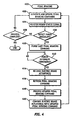
- FIG. 4 is a flow chart that illustrates a pedal braking process 400 suitable for use in connection with an electric brake system for an aircraft.
- the various tasks performed in connection with process 400 may be performed by software, hardware, firmware, or any combination thereof.
- the following description of process 400 may refer to elements mentioned above in connection with FIG. 1 and FIG. 2 .
- portions of process 400 may be performed by different elements of the described system, e.g., a BSCU, an EBAC, a brake mechanism, or a processing element of the electric brake system.
- process 400 may include any number of additional or alternative tasks, the tasks shown in FIG. 4 need not be performed in the illustrated order, and process 400 may be incorporated into a more comprehensive procedure or process having additional functionality not described in detail herein.
- Pedal braking process 400 preferably functions in this manner under normal conditions.
- process 400 can generate, update, and process pedal braking commands (task 402) in an ongoing manner while the aircraft operates the electric brake system in a pedal braking mode.
- pedal braking commands control electric actuation of at least one brake mechanism in the electric brake system, and such pedal braking commands are generated when the pilot depresses the aircraft brake pedal(s).
- process 400 can monitor one or more power status signals of the electric brake system (task 404) and detect the onset of a power interrupt condition (query task 406) in the manner described above for autobraking process 300.
- the onset of the power interrupt condition may cause pedal braking process 400 to proceed as described below beginning with task 410. If, however, process 400 does not detect a power interrupt condition (query task 406), then process 400 may check whether the braking operation is complete (query task 408). If braking is complete, then process 400 ends. If braking is not complete, then process 400 may be re-entered at task 402 to continue generating and updating the pedal braking commands as needed.
- pedal braking process 400 purges or deletes the last (or current) pedal braking command (task 410).
- the last pedal braking command is the most recent command generated by the electric brake system before the power interrupt. Depending upon the specific implementation of the electric brake system and the timing involved, the last pedal braking command may or may not have been executed by the brake mechanism(s).
- the last pedal braking command is purged to ensure that the electric braking system does not inadvertently refresh itself with that command when it regains normal operating power.
- Process 400 may idle until it determines that the power interrupt condition has terminated (query task 412). In other words, process 400 idles until normal operating power has been reestablished in the electric brake system.
- pedal braking process 400 may cause the electric brake system to release the electric brake actuator(s) in the brake mechanism(s) before the brakes are reapplied (task 414). This releasing of the actuators may be desirable to prepare them for subsequent activation and actuation. Moreover, this releasing of the actuators allows the electric brake system to wait until it receives the next pedal braking command (which is desirable to accommodate the situation where the pilot completely releases the brake pedals during the power interrupt). After releasing the actuators, process 400 refreshes the pedal braking command (task 416) by generating an updated pedal braking command that indicates the amount of brake pedal deflection that exists upon termination of the power interrupt condition. Process 400 can then process the updated pedal braking command (task 418) in an appropriate manner.
- the electric brake system processes the updated pedal braking command in a manner that provides seamless application of brakes upon termination of the power interrupt condition.
- the electric brake system controls the electric brake actuator(s) with the updated pedal braking command (task 420).
- the use of the updated pedal braking command ensures that the electric brake system accounts for any pilot interaction with the brake pedal(s) that may have occurred during the power interrupt period. This results in the expected amount of braking force applied by the pilot.
- the electric brake system can resume the normal pedal braking mode, as indicated by the arrow from task 420 to task 402.
Abstract
Description
- Embodiments of the present invention relate generally to an electric brake system for an aircraft. More particularly, embodiments of the present invention relate to a brake control scheme that gracefully handles power interrupts in the electric brake system.
- Under normal operating conditions, an electric brake system for an aircraft relies upon a continuous power supply (or supplies) that provide operating power for the processing components, electric brake actuators, and other elements of the electric brake system. The power supply (which may include an active power source that is driven by the aircraft engine or engines and/or a backup power supply such as a battery) need not be devoted to the electric brake system and, therefore, the supply voltages for the electric brake system may fluctuate within system tolerances in response to the current power demands of the aircraft. Under certain operating conditions the electric brake system may experience a very brief power interrupt during which a supply voltage to the electric brake system drops below a specified voltage.
- Even though aircraft typically recover from power interrupts in a very short time period, the resumption of nominal operating power for the electric brake system may result in discontinuous control of the electric brake actuators. Such discontinuities may cause the aircraft to lurch or apply the brakes in an unusual manner that is noticeable to the passengers and crew. For example, a power interrupt experienced during autobraking may trick the electric brake system, cause the control architecture to interpret the power interrupt as a lack of deceleration, and cause the control architecture to attempt an increase in the clamping force of the electric brake actuators in a compensating manner. Upon resumption of nominal operating power, however, the current state of the electric brake actuators may result in an "overbraking" condition that results in more deceleration than expected by the passengers and crew. On the other hand, a power interrupt experienced during pedal braking may cause the electric brake system to save the pre-interrupt values of the electric brake actuator control signals. Upon resumption of nominal operating power, however, the saved pre-interrupt values may not accurately reflect the current brake pedal deflection entered by the pilot. The effect on the aircraft will vary depending upon the difference (in both sign and magnitude) between the saved pre-interrupt values of the electric brake actuator control signals and the current post- interrupt values.
-
US-A-2001/0045771 describes an electromechanical braking system employing redundancy features so that, in the event of a partial power supply loss, alternative braking modes are implemented. The specific braking mode is determined in dependence upon the identity of the power source that has failed. -
EP-A-1,637,422 describes an elecctromechnical braking system for converting an electrical drive signal into mechanical energy to brake an aircraft wheel. Power is supplied from a DC main supply with a capacitively stored backup. - The techniques and technologies described herein control the operation of an electric brake system of an aircraft to reduce the noticeable side effects that may otherwise result from power interrupts experienced by the electric brake system. In connection with a pedal braking operation, one embodiment discards the pre-interrupt values of the electric brake actuator control signals and refreshes the values upon resumption of nominal operating power. These techniques enable the electric brake system to provide seamless application of the aircraft brakes in response to a power interrupt condition.
- The above and other techniques and technologies may be carried out in accordance with the invention, by a method of operating an electric brake system for an aircraft as set out in claim 1. The method involves monitoring a power status signal of the electric brake system, detecting onset of a power interrupt condition based upon the power status signal, and controlling the electric brake system to provide seamless application of brakes upon termination of the power interrupt condition.
- The above and other techniques and technologies may be carried out in accordance with a further aspect of the invention, by an electric brake system for an aircraft as defined in claim 5. The electric brake system includes a brake mechanism, an electric brake actuator coupled to the brake mechanism, and a brake control architecture coupled to the electric brake actuator. The brake control architecture includes processing logic that is configured to control actuation of the electric brake actuator, monitor a power status signal of the electric brake system, detect onset of a power interrupt condition based upon the power status signal, and control the electric brake actuator to provide seamless actuation of the brake mechanism upon termination of the power interrupt condition.
- Advantageously, the electric brake system comprises a brake system control unit; and monitoring the power status signal comprises monitoring an input power signal of the brake system control unit.
- Advantageously, the electric brake system comprises an electric brake actuator control; and monitoring the power status signal comprises monitoring an input power signal of the electric brake actuator control.
- Advantageously, the detecting onset of the power interrupt condition comprises: comparing the power status signal to a threshold voltage; and if the power status signal is less than the threshold voltage, indicating onset of the power interrupt condition.
- This summary is provided to introduce a selection of concepts in a simplified form that are further described below in the detailed description. This summary is not intended to identify key features or essential features of the claimed subject matter, nor is it intended to be used as an aid in determining the scope of the claimed subject matter.
- A more complete understanding of the present invention may be derived by referring to the detailed description and claims when considered in conjunction with the following figures, wherein like reference numbers refer to similar elements throughout the figures.
-
FIG. 1 is a simplified schematic representation of a portion of an electric brake system suitable for use in an aircraft; -
FIG. 2 is a schematic representation of a brake control architecture suitable for use in an electric brake system for an aircraft; -
FIG. 3 is a flow chart that illustrates an autobraking process suitable for use in connection with an electric brake system for an aircraft; and -
FIG. 4 is a flow chart that illustrates a pedal braking process suitable for use in connection with an electric brake system for an aircraft. - The following detailed description is merely illustrative in nature and is not intended to limit the embodiments of the invention or the application and uses of such embodiments. Furthermore, there is no intention to be bound by any expressed or implied theory presented in the preceding technical field, background, brief summary or the following detailed description.
- Embodiments of the invention may be described herein in terms of functional and/or logical block components and various processing steps. It should be appreciated that such block components may be realized by any number of hardware, software, and/or firmware components configured to perform the specified functions. For example, an embodiment of the invention may employ various integrated circuit components, e.g., memory elements, digital signal processing elements, logic elements, look-up tables, or the like, which may carry out a variety of functions under the control of one or more microprocessors or other control devices. In addition, those skilled in the art will appreciate that embodiments of the present invention may be practiced in conjunction with a variety of different aircraft brake systems and aircraft configurations, and that the system described herein is merely one example embodiment of the invention.
- For the sake of brevity, conventional techniques and components related to signal processing, aircraft brake systems, brake system controls, and other functional aspects of the systems (and the individual operating components of the systems) may not be described in detail herein. Furthermore, the connecting lines shown in the various figures contained herein are intended to represent example functional relationships and/or physical couplings between the various elements. It should be noted that many alternative or additional functional relationships or physical connections may be present in an embodiment of the invention.
- The following description refers to elements or nodes or features being "connected" or "coupled' together. As used herein, unless expressly stated otherwise, "connected" means that one element/node/feature is directly joined to (or directly communicates with) another element/node/feature, and not necessarily mechanically. Likewise, unless expressly stated otherwise, "coupled" means that one element/node/feature is directly or indirectly joined to (or directly or indirectly communicates with) another element/node/feature, and not necessarily mechanically. Thus, although the schematics shown in
FIG. 1 and FIG. 2 depict example arrangement of elements, additional intervening elements, devices, features, or components may be present in an embodiment of the invention. -
FIG. 1 is a schematic representation of a portion of anelectric brake system 100 suitable for use in an aircraft (not shown).Electric brake system 100 includes abrake pedal 102, a brake system control unit (BSCU) 104 coupled tobrake pedal 102, an electric brake actuator control (EBAC) 106 coupled toBSCU 104, and abrake mechanism 108 coupled to EBAC 106.Brake mechanism 108 corresponds to at least onewheel 110 of the aircraft.Electric brake system 100 may also include an axle-mounted remote data concentrator (RDC) 112 coupled towheel 110. Briefly, BSCU 104 reacts to manipulation ofbrake pedal 102 and generates control signals that are received by EBAC 106. In turn, EBAC 106 generates brake mechanism control signals that are received bybrake mechanism 108. In turn,brake mechanism 108 actuates to slow the rotation ofwheel 110. These features and components are described in more detail below. -
Electric brake system 100 can be applied to any number of electric braking configurations for an aircraft, andelectric brake system 100 is depicted in a simplified manner for ease of description. An embodiment ofelectric brake system 100 may include a left subsystem architecture and a right subsystem architecture, where the terms "left" and "right" refer to the port and starboard of the aircraft, respectively. In practice, the two subsystem architectures may be independently controlled in the manner described below. In this regard, an embodiment ofelectric brake system 100 as deployed may include a left brake pedal, a right brake pedal, a left BSCU, a right BSCU, any number of left EBACs coupled to and controlled by the left BSCU, any number of right EBACs coupled to and controlled by the right BSCU, a brake mechanism for each wheel (or for each group of wheels), and an RDC for each wheel (or for each group of wheels). In operation, the electric brake system can independently generate and apply brake actuator control signals for each wheel of the aircraft or concurrently for any group of wheels. -
Brake pedal 102 is configured to provide pilot input toelectric brake system 100 during pedal braking operations. The pilot physically manipulatesbrake pedal 102, resulting in deflection or movement (i.e., some form of physical input) ofbrake pedal 102. This physical deflection is measured from its natural position by a hardware servo or an equivalent component, converted into a BSCU pilot command control signal by a transducer or an equivalent component, and sent toBSCU 104. The BSCU pilot command control signal may convey brake pedal sensor data that may include or indicate the deflection position forbrake pedal 102, the deflection rate forbrake pedal 102, a desired braking condition forbrake mechanism 108, or the like. - An embodiment of
electric brake system 100 may use any number ofBSCUs 104. For ease of description, this example includes only oneBSCU 104.BSCU 104 is an electronic control unit that has embedded software that digitally computes EBAC control signals that represent braking commands. The electrical/software implementation allows further optimization and customization of braking performance and feel if needed for the given aircraft deployment. -
BSCU 104 may be implemented or performed with a general purpose processor, a content addressable memory, a digital signal processor, an application specific integrated circuit, a field programmable gate array, any suitable programmable logic device, discrete gate or transistor logic, discrete hardware components, or any combination thereof, designed to perform the functions described herein. A processor may be realized as a microprocessor, a controller, a microcontroller, or a state machine. A processor may also be implemented as a combination of computing devices, e.g., a combination of a digital signal processor and a microprocessor, a plurality of microprocessors, one or more microprocessors in conjunction with a digital signal processor core, or any other such configuration. In one embodiment,BSCU 104 is implemented with a computer processor (such as a PowerPC 555) that hosts software and provides external interfaces for the software. -
BSCU 104 monitors various aircraft inputs to provide control functions such as, without limitation: pedal braking; parking braking; autobraking; and gear retract braking. In addition,BSCU 104 blends antiskid commands (which could be generated internally or externally from BSCU 104) to provide enhanced control of braking.BSCU 104 obtains pilot command control signals frombrake pedal 102, along with wheel data (e.g., wheel speed, rotational direction, tire pressure, etc.) fromRDC 112.BSCU 104 processes its input signals and generates one or more EBAC control signals that are received byEBAC 106. In practice,BSCU 104 transmits the EBAC control signals to EBAC 106 via a digital data bus. In a generalized architecture (not shown), each BSCU can generate independent output signals for use with any number of EBACs under its control. -
BSCU 104 may be coupled to one or more associatedEBACs 106.EBAC 106 may be implemented, performed, or realized in the manner described above forBSCU 104. In one embodiment,EBAC 106 is realized with a computer processor (such as a PowerPC 555) that hosts software, provides external interfaces for the software, and includes suitable processing logic that is configured to carry out the various EBAC operations described herein.EBAC 106 obtains EBAC control signals fromBSCU 104, processes the EBAC control signals, and generates the brake mechanism control signals (brake actuator signals) forbrake mechanism 108. - Notably, the functionality of
BSCU 104 andEBAC 106 may be combined into a single processor-based feature or component. In this regard,BSCU 104,EBAC 106, or the combination thereof can be considered to be a brake control architecture forelectric brake system 100. Such a brake control architecture includes suitably configured processing logic, functionality, and features that support the brake control operations described herein. -
Wheel 110 may include an associatedbrake mechanism 108, which includes or is coupled to at least one electric brake actuator configured to impart clamping force to a brake rotor ofbrake mechanism 108.EBAC 106controls brake mechanism 108 to apply, release, modulate, and otherwise control the actuation of the respective electric brake actuators. In this regard,EBAC 106 generates the brake mechanism control signals in response to the respective EBAC control signals generated byBSCU 104. The brake mechanism control signals are suitably formatted and arranged for compatibility with theparticular brake mechanism 108 utilized by the aircraft. In practice, the brake mechanism control signals may be regulated to carry out anti-skid and other braking maneuvers. Those skilled in the art are familiar with aircraft brake mechanisms and the general manner in which they are controlled, and such known aspects will not be described in detail here. -
Electric brake system 100 may include or communicate with one or more sensors forwheel 110. These sensors are suitably configured to measure wheel data (wheel speed, direction of wheel rotation, tire pressure, wheel/brake temperature, etc.) forwheel 110, where the wheel data can be utilized byelectrical braking system 100.RDC 112 is generally configured to receive, measure, detect, or otherwise obtain data for processing and/or transmission to another component ofelectric brake system 100. Here,RDC 112 is coupled to (or is otherwise associated with)wheel 110, andRDC 112 is configured to collect and transmit its wheel data toBSCU 104. The digital data communication bus or buses on the aircraft may be configured to communicate the wheel data fromRDC 112 toBSCU 104 using any suitable data communication protocol and any suitable data transmission scheme. In an alternate embodiment,RDC 112 may be configured to communicate the wheel data toEBAC 106. In yet another embodiment,RDC 112 may be configured to communicate the wheel data (or portions thereof) to bothBSCU 104 andEBAC 106. -
Electric brake system 100 may include or cooperate with a suitably configured power control unit orsubsystem 114.Power control unit 114 may be coupled toBSCU 104,EBAC 106,brake mechanism 108, and/or to other components ofelectric brake system 100.Power control unit 114 may be configured to regulate, remove, or otherwise control power to one or more components ofelectric brake system 100 as needed to achieve a desired operating power mode.Power control unit 114 may also be configured to monitor the aircraft power systems and power buses that feedelectric brake system 100. For example,power control unit 114 may be coupled to an active power supply and/or to a backup power supply (e.g., a battery) for the aircraft. The active power supply may include a generator coupled to an engine and a suitably configured AC-to-DC converter, such as a transformer rectifier unit (TRU). In this embodiment, the active power supply provides power generated from the aircraft engine(s), while the backup power supply provides power to the aircraft when the engine(s) are not running.Power control unit 114 may be suitably configured to provide operating power toelectric brake system 100 from the active power supply and/or the backup power supply as needed to support the functionality ofelectric brake system 100. -
FIG. 2 is a schematic representation of abrake control architecture 200 suitable for use in an electric brake system for an aircraft.Electric brake system 100 may employ an embodiment ofbrake control architecture 200. For example,brake control architecture 200 may be implemented or realized inBSCU 104 and/orEBAC 106.Brake control architecture 200 may include, without limitation: aprocessor 202 having suitably configured processing logic; an appropriate amount ofmemory 204; a brake mechanismcontrol signal generator 206;autobraking control logic 208; pedalbraking control logic 210; and power interruptdetection logic 212. These elements may be coupled together using adata communication bus 214 or any suitably configured interconnection architecture or arrangement. In this embodiment,brake control architecture 200 is configured to control the electric brake system in a manner that seamlessly handles power interrupt conditions, as described in more detail below. -
Processor 202 may be implemented, performed, or realized in the manner described above forBSCU 104. The processing logic corresponding toprocessor 202 is designed to carry out various operations and functions associated with the electric brake control schemes described herein. Furthermore, a method or algorithm (or portions thereof) described in connection with the embodiments disclosed herein may be embodied directly in hardware, in firmware, in a software module executed byprocessor 202, or in any practical combination thereof. A software module may reside inmemory 204, which may be realized as one or more physical components having RAM memory, flash memory, ROM memory, EPROM memory, EEPROM memory, registers, a hard disk, a removable disk, a CD-ROM, or any other form of storage medium known in the art. In this regard,memory 204 can be coupled toprocessor 202 such thatprocessor 202 can read information from, and write information to,memory 204. In the alternative,memory 204 may be integral toprocessor 202. As an example,processor 202 andmemory 204 may reside in an ASIC. - Although depicted separately from
processor 202 inFIG. 2 , brake mechanismcontrol signal generator 206,autobraking control logic 208, pedalbraking control logic 210, and/or power interrupt detection logic 212 (or portions thereof) may be implemented inprocessor 202. These functional elements are shows as distinct blocks for clarity and ease of description. -
Memory 204 may be configured to store at least one savedautobrake command 216 for the electric brake system. Autobrake commands control electric actuation of the brake mechanisms in the electric brake system. In this embodiment, savedautobrake commands 216 may be retrieved and processed following a power interrupt condition to provide seamless application of the aircraft brakes during autobraking. In this regard, the operation of brake mechanismcontrol signal generator 206 may be influenced by saved autobrake commands 216. - Brake mechanism
control signal generator 206, which may be realized in the processing logic ofprocessor 202, is suitably configured to generate control signals for the aircraft brake mechanism(s). Referring toFIG. 1 , brake mechanismcontrol signal generator 206 may be implemented inBSCU 104 and therefore configured to generate or influence EBAC control signals, and/or implemented inEBAC 106 and therefore configured to generate or influence brake mechanism control signals. -
Autobraking control logic 208, which may be realized in the processing logic ofprocessor 202, represents the processing intelligence that enables the aircraft to operate the electric brake system in an autobrake mode. Aircraft autobraking can be utilized during a landing operation to enhance the efficiency and performance of the electric brake system. In connection with a typical autobraking operation, the pilot selects a level of autobraking corresponding to a desired deceleration of the aircraft. After the aircraft lands, the autobraking function monitors the actual deceleration and speed of the aircraft and adjusts the actuation of the brake mechanisms in an automated fashion to achieve the desired deceleration characteristic. - Pedal
braking control logic 210, which may be realized in the processing logic ofprocessor 202, represents the processing intelligence that enables the aircraft to operate the electric brake system in a pedal braking mode. Such pedal braking relies upon pilot input and deflection of the brake pedals (as described above in the context ofFIG. 1 ). - Power interrupt
detection logic 212, which may be realized in the processing logic ofprocessor 202, represents the processing intelligence that enables the electric brake system to detect the onset (and termination) of a power interrupt condition. In typical aircraft applications, such power interrupts are very brief-they may last only 50-100 milliseconds. For this embodiment, power interruptdetection logic 212 analyzes a power status signal of the electric brake system to determine whether or not a power interrupt has occurred or is about to occur. The power status signal may represent an input power or voltage signal of a BSCU, an input power or voltage signal of an EBAC, and/or any voltage, current, or power level that is present in the electric brake system or the aircraft. Power interruptdetection logic 212 may be configured to compare the power status signal to a threshold level, potential, or voltage, and to indicate the onset of a power interrupt condition if the power status signal falls below the threshold level. For example, if the nominal operating voltage of the electric brake system is about 28 volts and the normal operating voltage range is 18 to 32 volts, power interruptdetection logic 212 can indicate a power interrupt condition if the voltage drops below 18 volts. -
FIG. 3 is a flow chart that illustrates anautobraking process 300 suitable for use in connection with an electric brake system for an aircraft. The various tasks performed in connection withprocess 300 may be performed by software, hardware, firmware, or any combination thereof. For illustrative purposes, the following description ofprocess 300 may refer to elements mentioned above in connection withFIG. 1 and FIG. 2 . In embodiments of the invention, portions ofprocess 300 may be performed by different elements of the described system, e.g., a BSCU, an EBAC, a brake mechanism, or a processing element of the electric brake system. It should be appreciated thatprocess 300 may include any number of additional or alternative tasks, the tasks shown inFIG. 3 need not be performed in the illustrated order, andprocess 300 may be incorporated into a more comprehensive procedure or process having additional functionality not described in detail herein. - A typical autobraking procedure was described above in the context of
autobraking control logic 208.Autobraking process 300 preferably functions in this manner under normal conditions. In this regard,process 300 can generate, update, and process autobrake commands (task 302) in an ongoing manner while the aircraft operates the electric brake system in an autobraking mode. As mentioned above, autobrake commands control electric actuation of at least one brake mechanism in the electric brake system, and such autobrake commands need not be dependent upon any real-time pilot input. While operating in the autobrake mode,process 300 can monitor one or more power status signals of the electric brake system (task 304). Duringtask 304, the power status signal may be continuously monitored or sampled at a suitable frequency. The monitored power status signal may be, without limitation: an input power/voltage of a BSCU; an input power/voltage of an EBAC; an input power/voltage of a brake mechanism; or the like.Process 300 analyzes the real-time value of this power status signal to detect the onset of a power interrupt condition (query task 306). - In connection with
query task 306,autobraking process 300 may compare the current value of the power status signal to a threshold value, such as a threshold voltage. If the current value of the power status signal is less than the threshold value, then process 300 may indicate that a power interrupt condition has occurred or is about to occur. In practice, the indication of the onset of the power interrupt condition may simply be an internally generated flag or identifier that instructsprocess 300 to proceed as described below beginning withtask 310. If, however,process 300 does not detect a power interrupt condition (query task 306), then process 300 may check whether autobraking is complete (query task 308). If autobraking is complete, then process 300 ends. If autobraking is not complete, then process 300 may be re-entered attask 302 to continue generating and updating the autobrake commands as needed. - In response to the detection of a power interrupt condition,
autobraking process 300 stores the last autobrake command (task 310) as a saved autobrake command in a suitable memory location. The last autobrake command is the most recent autobrake command generated by the electric brake system before the power interrupt. Depending upon the specific implementation of the electric brake system and the timing involved, the last autobrake command may or may not have been executed by the brake mechanism(s). In addition,process 300 may pause autobrake command calculations during the power interrupt to prevent the autobrake algorithm from ramping up its brake application command when the brake mechanisms are incapable of being applied (which might occur during the power interrupt). The saved autobrake command is preserved untilprocess 300 determines that the power interrupt condition has terminated (query task 312). In other words,process 300 idles until normal operating power has been reestablished in the electric brake system. - When normal operating power resumes,
autobraking process 300 can retrieve the saved autobrake command (task 314) from memory and process the saved autobrake command (task 316) in an appropriate manner. For this embodiment, the electric brake system processes the saved autobrake command in a manner that provides seamless application of brakes upon termination of the power interrupt condition. In particular, the electric brake system controls the electric brake actuator(s) with the saved autobrake command (task 318). In practice, the use of the saved autobrake command ensures that the most recent brake actuation state is preserved. Otherwise, the electric brake system may inadvertently increase or decrease the amount of brake clamping force by an excessive amount that results in lurching or jerking of the aircraft when normal operating power resumes. - Once normal operating power has been reestablished, the electric brake system can generate an updated autobrake command (task 320) if needed. After processing the saved autobrake command,
autobraking process 300 can replace the saved autobrake command with the updated autobrake command (task 322) and process the updated autobrake command in an appropriate manner, In other words, once the saved autobrake command has been retrieved and utilized by the electric brake system, the normal autobrake operating mode can be resumed, as indicated by the arrow fromtask 322 totask 302. -
FIG. 4 is a flow chart that illustrates apedal braking process 400 suitable for use in connection with an electric brake system for an aircraft. The various tasks performed in connection withprocess 400 may be performed by software, hardware, firmware, or any combination thereof. For illustrative purposes, the following description ofprocess 400 may refer to elements mentioned above in connection withFIG. 1 and FIG. 2 . In embodiments of the invention, portions ofprocess 400 may be performed by different elements of the described system, e.g., a BSCU, an EBAC, a brake mechanism, or a processing element of the electric brake system. It should be appreciated thatprocess 400 may include any number of additional or alternative tasks, the tasks shown inFIG. 4 need not be performed in the illustrated order, andprocess 400 may be incorporated into a more comprehensive procedure or process having additional functionality not described in detail herein. - A typical pedal braking procedure was described above.
Pedal braking process 400 preferably functions in this manner under normal conditions. In this regard,process 400 can generate, update, and process pedal braking commands (task 402) in an ongoing manner while the aircraft operates the electric brake system in a pedal braking mode. As mentioned above, pedal braking commands control electric actuation of at least one brake mechanism in the electric brake system, and such pedal braking commands are generated when the pilot depresses the aircraft brake pedal(s). While operating in the pedal braking mode,process 400 can monitor one or more power status signals of the electric brake system (task 404) and detect the onset of a power interrupt condition (query task 406) in the manner described above forautobraking process 300. - The onset of the power interrupt condition may cause
pedal braking process 400 to proceed as described below beginning withtask 410. If, however,process 400 does not detect a power interrupt condition (query task 406), then process 400 may check whether the braking operation is complete (query task 408). If braking is complete, then process 400 ends. If braking is not complete, then process 400 may be re-entered attask 402 to continue generating and updating the pedal braking commands as needed. - In response to the detection of a power interrupt condition,
pedal braking process 400 purges or deletes the last (or current) pedal braking command (task 410). The last pedal braking command is the most recent command generated by the electric brake system before the power interrupt. Depending upon the specific implementation of the electric brake system and the timing involved, the last pedal braking command may or may not have been executed by the brake mechanism(s). The last pedal braking command is purged to ensure that the electric braking system does not inadvertently refresh itself with that command when it regains normal operating power.Process 400 may idle until it determines that the power interrupt condition has terminated (query task 412). In other words,process 400 idles until normal operating power has been reestablished in the electric brake system. - When normal operating power resumes,
pedal braking process 400 may cause the electric brake system to release the electric brake actuator(s) in the brake mechanism(s) before the brakes are reapplied (task 414). This releasing of the actuators may be desirable to prepare them for subsequent activation and actuation. Moreover, this releasing of the actuators allows the electric brake system to wait until it receives the next pedal braking command (which is desirable to accommodate the situation where the pilot completely releases the brake pedals during the power interrupt). After releasing the actuators,process 400 refreshes the pedal braking command (task 416) by generating an updated pedal braking command that indicates the amount of brake pedal deflection that exists upon termination of the power interrupt condition.Process 400 can then process the updated pedal braking command (task 418) in an appropriate manner. For this embodiment, the electric brake system processes the updated pedal braking command in a manner that provides seamless application of brakes upon termination of the power interrupt condition. In particular, the electric brake system controls the electric brake actuator(s) with the updated pedal braking command (task 420). In practice, the use of the updated pedal braking command ensures that the electric brake system accounts for any pilot interaction with the brake pedal(s) that may have occurred during the power interrupt period. This results in the expected amount of braking force applied by the pilot. Once normal operating power has been reestablished, the electric brake system can resume the normal pedal braking mode, as indicated by the arrow fromtask 420 totask 402. - While at least one example embodiment has been presented in the foregoing detailed description, it should be appreciated that a vast number of variations exist. It should also be appreciated that the example embodiment or embodiments described herein are not intended to limit the scope, applicability, or configuration of the invention in any way. Rather, the foregoing detailed description will provide those skilled in the art with a convenient road map for implementing the described embodiment or embodiments. It should be understood that various changes can be made in the function and arrangement of elements without departing from the scope of the invention, where the scope of the invention is defined by the claims, which includes known equivalents and foreseeable equivalents at the time of filing this patent application.
Claims (9)
- A method (300, 400) of operating an electric brake system (100) for an aircraft, the method comprising:operating the electric brake system in a pedal braking mode;monitoring (304, 404) a power status signal of the electric brake system (100);detecting (306, 406) onset of a power interrupt condition based upon the power status signal;purging (410) a current pedal braking command in response to detecting (406) onset of the power interrupt condition, the current pedal braking command controlling electric actuation of a brake mechanism (108) in the electric brake system (100);generating (416) an updated pedal braking command that indicates brake pedal deflection upon termination of the power interrupt condition; andcontrolling (318, 420) the electric brake system (100) to provide seamless application of brakes upon termination of the power interrupt condition, wherein controlling (420) the electric brake system comprises processing (418) the updated pedal braking command.
- A method (300, 400) according to claim 1, wherein:the electric brake system (100) comprises a brake system control unit (104); andmonitoring (304, 404) the power status signal comprises monitoring an input power signal of the brake system control unit (104).
- A method (300, 400) according to claim 1, wherein:the electric brake system (100) comprises an electric brake actuator control (106); andmonitoring (304, 404) the power status signal comprises monitoring an input power signal of the electric brake actuator control (106).
- A method (400) according to claim 1, further comprising releasing (414) an electric brake actuator in the brake mechanism (108) upon termination of the power interrupt condition, wherein controlling (420) the electric brake system (100) occurs after releasing (414) the electric brake actuator.
- A method (300, 400) according to claim 1, wherein detecting (306, 406) onset of the power interrupt condition comprises:comparing the power status signal to a threshold voltage; andif the power status signal is less than the threshold voltage, indicating onset of the power interrupt condition.
- An electric brake system for an aircraft, the electric brake system comprising:a brake mechanism;an electric brake actuator coupled to the brake mechanism (108); anda brake control architecture coupled to the electric brake actuator, the brake control architecture comprising processing logic (202) configured to:operate the electric brake system in a pedal braking mode (400);control actuation of the electric brake actuator,monitor a power status signal of the electric brake system;detect onset of a power interrupt condition based upon the power status signal;purge a current pedal braking command in response to onset of the power interrupt condition (410);generate an updated pedal braking command (402) that indicates current brake pedal deflection upon termination of the power interrupt condition; andcontrol the electric brake actuator to provide seamless actuation of the brake mechanism upon termination of the power interrupt condition, wherein pedal braking commands control operation of the electric brake actuator.
- An electric brake system according to claim 6, wherein:the brake control architecture comprises a brake system control unit (104); andthe power status signal represents an input power signal of the brake system control unit.
- An electric brake system according to claim 6, wherein:the brake control architecture comprises an electric brake actuator control (106); andthe power status signal represents an input power signal of the electric brake actuator control.
- An electric brake system according to claim 6, wherein:the processing logic of the brake control architecture is configured to release the electric brake actuator upon termination of the power interrupt condition (414); andthe updated pedal braking command is generated and processed after releasing the electric brake actuator.
Applications Claiming Priority (2)
| Application Number | Priority Date | Filing Date | Title |
|---|---|---|---|
| US11/535,449 US7784882B2 (en) | 2006-09-26 | 2006-09-26 | Power interrupt management for an aircraft electric brake system |
| EP07873752A EP2069170B1 (en) | 2006-09-26 | 2007-08-24 | Power interrupt management for an aircraft electric brake system |
Related Parent Applications (1)
| Application Number | Title | Priority Date | Filing Date |
|---|---|---|---|
| EP07873752.5 Division | 2007-08-24 |
Publications (2)
| Publication Number | Publication Date |
|---|---|
| EP2277752A1 EP2277752A1 (en) | 2011-01-26 |
| EP2277752B1 true EP2277752B1 (en) | 2013-07-03 |
Family
ID=39224168
Family Applications (2)
| Application Number | Title | Priority Date | Filing Date |
|---|---|---|---|
| EP07873752A Active EP2069170B1 (en) | 2006-09-26 | 2007-08-24 | Power interrupt management for an aircraft electric brake system |
| EP10009500.9A Active EP2277752B1 (en) | 2006-09-26 | 2007-08-24 | Power interrupt management for an aircraft electric brake system |
Family Applications Before (1)
| Application Number | Title | Priority Date | Filing Date |
|---|---|---|---|
| EP07873752A Active EP2069170B1 (en) | 2006-09-26 | 2007-08-24 | Power interrupt management for an aircraft electric brake system |
Country Status (9)
| Country | Link |
|---|---|
| US (1) | US7784882B2 (en) |
| EP (2) | EP2069170B1 (en) |
| JP (2) | JP5330244B2 (en) |
| CN (1) | CN101516695B (en) |
| AT (1) | ATE486753T1 (en) |
| CA (2) | CA2745738C (en) |
| DE (1) | DE602007010328D1 (en) |
| ES (2) | ES2424234T3 (en) |
| WO (1) | WO2008105821A2 (en) |
Families Citing this family (13)
| Publication number | Priority date | Publication date | Assignee | Title |
|---|---|---|---|---|
| US8244428B2 (en) * | 2006-05-10 | 2012-08-14 | The Boeing Company | Automatic fore-aft detection for an aircraft |
| US7784882B2 (en) | 2006-09-26 | 2010-08-31 | The Boeing Company | Power interrupt management for an aircraft electric brake system |
| US20100038188A1 (en) * | 2006-10-24 | 2010-02-18 | Goodrich Corporation | Aircraft brake actuation measurement unit |
| US7857107B2 (en) * | 2006-11-01 | 2010-12-28 | The Boeing Company | Ground towing power architecture for an electric brake system of an aircraft |
| DE102009046231A1 (en) * | 2009-10-30 | 2011-05-05 | Robert Bosch Gmbh | Electric Brake System, particularly electro-mechanical brake system for motor vehicle, has brake circuit, and control unit for implementation of driver braking demand |
| US8423256B2 (en) * | 2009-12-23 | 2013-04-16 | Goodrich Corporation | Systems and methods for adaptive deceleration |
| CN102092373B (en) * | 2010-12-16 | 2013-09-04 | 西安航空制动科技有限公司 | Automatic braking method and device for plane |
| US9811130B2 (en) | 2011-09-12 | 2017-11-07 | The Boeing Company | Power management control system |
| JP6706877B2 (en) * | 2012-09-12 | 2020-06-10 | ザ・ボーイング・カンパニーThe Boeing Company | Power management control system |
| CA2902662C (en) * | 2013-03-06 | 2020-08-04 | Bombardier Inc. | Electric braking system and method relying on voltage hysteresis for applied brake power control |
| JP6297883B2 (en) * | 2014-03-28 | 2018-03-20 | マツダ株式会社 | Electric brake device |
| US10308352B2 (en) * | 2014-12-12 | 2019-06-04 | Borealis Technical Limited | Monitoring system for aircraft drive wheel system |
| GB2555834A (en) * | 2016-11-11 | 2018-05-16 | Airbus Operations Ltd | Braking energy dissipation |
Family Cites Families (20)
| Publication number | Priority date | Publication date | Assignee | Title |
|---|---|---|---|---|
| US1004A (en) * | 1838-11-09 | Abnee e | ||
| FR2608975B1 (en) * | 1986-12-26 | 1989-11-17 | Messier Hispano Sa | AIRCRAFT BRAKE CONTROL DEVICE |
| JP2807837B2 (en) * | 1989-12-01 | 1998-10-08 | 日清紡績株式会社 | Failure detection circuit of anti-skid control device |
| DE4117099A1 (en) * | 1991-03-30 | 1992-10-01 | Teves Gmbh Alfred | CIRCUIT ARRANGEMENT FOR A REGULATOR |
| DE4339570B4 (en) * | 1993-11-19 | 2004-03-04 | Robert Bosch Gmbh | Electronic braking system |
| US6003640A (en) | 1997-05-09 | 1999-12-21 | The B.F. Goodrich Company | Electronic braking system with brake wear measurement and running clearance adjustment |
| US6317675B1 (en) * | 1997-11-22 | 2001-11-13 | Continental Teves Ag & Co., Ohg | Electromechanical brake system |
| US6095293A (en) | 1998-02-13 | 2000-08-01 | The B. F. Goodrich Company | Aircraft brake and method with electromechanical actuator modules |
| US6513885B1 (en) * | 1999-05-14 | 2003-02-04 | Hydro-Aire, Inc. | Dual redundant active/active brake-by-wire architecture |
| EP1080009B1 (en) * | 1999-05-14 | 2002-12-18 | Hydro-Aire, Inc. | Dual redundant active/active brake-by-wire architecture |
| US6402259B2 (en) * | 1999-07-14 | 2002-06-11 | Goodrich Corporation | Electromechanical braking system with power distribution and redundancy |
| JP3867268B2 (en) * | 2001-12-28 | 2007-01-10 | 株式会社日立製作所 | Electric disc brake device |
| FR2852144B1 (en) | 2003-03-05 | 2005-06-10 | Commissariat Energie Atomique | METHOD FOR DELIMITATING A CONDUCTIVE ELEMENT HAVING AN INSULATING LAYER, DEVICE AND TRANSISTOR OBTAINED THEREBY |
| US7128376B2 (en) * | 2003-05-30 | 2006-10-31 | Goodrich Corporation | Redundant architecture for brake-by-wire system |
| JP4715079B2 (en) * | 2003-06-26 | 2011-07-06 | パナソニック株式会社 | Vehicle power supply |
| FR2857642B1 (en) * | 2003-07-16 | 2006-02-03 | Messier Bugatti | INTEMPESTIVE BRAKE PROTECTION DEVICE ESPECIALLY ADAPTED TO AN ELECTROMECHANICAL BRAKE |
| US6984001B2 (en) * | 2003-09-29 | 2006-01-10 | Haldex Brake Products Ab | Power supply network for brake system |
| US20060061210A1 (en) * | 2004-09-17 | 2006-03-23 | Mihai Ralea | Electromechanical braking system with electrical energy back-up |
| FR2880602B1 (en) * | 2005-01-11 | 2007-03-16 | Messier Bugatti Sa | PROTECTIVE METHOD IN A BRAKE SYSTEM OF A VEHICLE WITH ELECTRIC BRAKES |
| US7784882B2 (en) | 2006-09-26 | 2010-08-31 | The Boeing Company | Power interrupt management for an aircraft electric brake system |
-
2006
- 2006-09-26 US US11/535,449 patent/US7784882B2/en active Active
-
2007
- 2007-08-24 AT AT07873752T patent/ATE486753T1/en not_active IP Right Cessation
- 2007-08-24 ES ES10009500T patent/ES2424234T3/en active Active
- 2007-08-24 EP EP07873752A patent/EP2069170B1/en active Active
- 2007-08-24 CA CA2745738A patent/CA2745738C/en active Active
- 2007-08-24 ES ES07873752T patent/ES2353627T3/en active Active
- 2007-08-24 WO PCT/US2007/018829 patent/WO2008105821A2/en active Application Filing
- 2007-08-24 DE DE602007010328T patent/DE602007010328D1/en active Active
- 2007-08-24 CA CA2659444A patent/CA2659444C/en active Active
- 2007-08-24 EP EP10009500.9A patent/EP2277752B1/en active Active
- 2007-08-24 CN CN2007800358147A patent/CN101516695B/en active Active
- 2007-08-24 JP JP2009529177A patent/JP5330244B2/en active Active
-
2013
- 2013-01-07 JP JP2013000535A patent/JP5643848B2/en active Active
Also Published As
| Publication number | Publication date |
|---|---|
| CN101516695A (en) | 2009-08-26 |
| CA2745738A1 (en) | 2008-09-04 |
| DE602007010328D1 (en) | 2010-12-16 |
| EP2069170A2 (en) | 2009-06-17 |
| CA2659444A1 (en) | 2008-09-04 |
| JP5330244B2 (en) | 2013-10-30 |
| EP2069170B1 (en) | 2010-11-03 |
| CA2745738C (en) | 2014-03-18 |
| JP2013100097A (en) | 2013-05-23 |
| WO2008105821A3 (en) | 2008-11-13 |
| ES2353627T3 (en) | 2011-03-03 |
| ATE486753T1 (en) | 2010-11-15 |
| US20080073970A1 (en) | 2008-03-27 |
| JP2010504875A (en) | 2010-02-18 |
| CN101516695B (en) | 2012-09-05 |
| US7784882B2 (en) | 2010-08-31 |
| CA2659444C (en) | 2011-11-08 |
| JP5643848B2 (en) | 2014-12-17 |
| ES2424234T3 (en) | 2013-09-30 |
| WO2008105821A2 (en) | 2008-09-04 |
| EP2277752A1 (en) | 2011-01-26 |
Similar Documents
| Publication | Publication Date | Title |
|---|---|---|
| EP2277752B1 (en) | Power interrupt management for an aircraft electric brake system | |
| EP2094549B1 (en) | Reduced power mode for an aircraft electric brake system | |
| US9139292B2 (en) | System and methods for dynamically stable braking | |
| US7618100B2 (en) | Braking interlock for an electric brake system of an aircraft | |
| US11312343B2 (en) | Motor vehicle control unit for an electric parking brake | |
| EP2097300B1 (en) | Electric brake system for an aircraft | |
| US8393689B2 (en) | Autobraking interlock for an aircraft electric brake system | |
| US6296325B1 (en) | Method to connect and distribute power to an electromechanical braking system | |
| US8641154B2 (en) | Parking brake adjustment for an aircraft having an electric brake system | |
| US20070222284A1 (en) | Brake control system | |
| JP2002274348A (en) | Brake device for automobile and its control method | |
| JP2729755B2 (en) | Torque control type anti-skid braking method and device |
Legal Events
| Date | Code | Title | Description |
|---|---|---|---|
| PUAI | Public reference made under article 153(3) epc to a published international application that has entered the european phase |
Free format text: ORIGINAL CODE: 0009012 |
|
| AC | Divisional application: reference to earlier application |
Ref document number: 2069170 Country of ref document: EP Kind code of ref document: P |
|
| AK | Designated contracting states |
Kind code of ref document: A1 Designated state(s): AT BE BG CH CY CZ DE DK EE ES FI FR GB GR HU IE IS IT LI LT LU LV MC MT NL PL PT RO SE SI SK TR |
|
| 17P | Request for examination filed |
Effective date: 20110726 |
|
| GRAP | Despatch of communication of intention to grant a patent |
Free format text: ORIGINAL CODE: EPIDOSNIGR1 |
|
| GRAS | Grant fee paid |
Free format text: ORIGINAL CODE: EPIDOSNIGR3 |
|
| GRAA | (expected) grant |
Free format text: ORIGINAL CODE: 0009210 |
|
| AC | Divisional application: reference to earlier application |
Ref document number: 2069170 Country of ref document: EP Kind code of ref document: P |
|
| AK | Designated contracting states |
Kind code of ref document: B1 Designated state(s): AT BE BG CH CY CZ DE DK EE ES FI FR GB GR HU IE IS IT LI LT LU LV MC MT NL PL PT RO SE SI SK TR |
|
| REG | Reference to a national code |
Ref country code: GB Ref legal event code: FG4D |
|
| REG | Reference to a national code |
Ref country code: AT Ref legal event code: REF Ref document number: 619531 Country of ref document: AT Kind code of ref document: T Effective date: 20130715 Ref country code: CH Ref legal event code: EP |
|
| REG | Reference to a national code |
Ref country code: IE Ref legal event code: FG4D |
|
| REG | Reference to a national code |
Ref country code: DE Ref legal event code: R096 Ref document number: 602007031490 Country of ref document: DE Effective date: 20130829 |
|
| REG | Reference to a national code |
Ref country code: ES Ref legal event code: FG2A Ref document number: 2424234 Country of ref document: ES Kind code of ref document: T3 Effective date: 20130930 |
|
| PG25 | Lapsed in a contracting state [announced via postgrant information from national office to epo] |
Ref country code: SI Free format text: LAPSE BECAUSE OF FAILURE TO SUBMIT A TRANSLATION OF THE DESCRIPTION OR TO PAY THE FEE WITHIN THE PRESCRIBED TIME-LIMIT Effective date: 20130703 |
|
| REG | Reference to a national code |
Ref country code: AT Ref legal event code: MK05 Ref document number: 619531 Country of ref document: AT Kind code of ref document: T Effective date: 20130703 |
|
| REG | Reference to a national code |
Ref country code: NL Ref legal event code: VDEP Effective date: 20130703 |
|
| REG | Reference to a national code |
Ref country code: LT Ref legal event code: MG4D |
|
| PG25 | Lapsed in a contracting state [announced via postgrant information from national office to epo] |
Ref country code: CY Free format text: LAPSE BECAUSE OF FAILURE TO SUBMIT A TRANSLATION OF THE DESCRIPTION OR TO PAY THE FEE WITHIN THE PRESCRIBED TIME-LIMIT Effective date: 20130918 Ref country code: AT Free format text: LAPSE BECAUSE OF FAILURE TO SUBMIT A TRANSLATION OF THE DESCRIPTION OR TO PAY THE FEE WITHIN THE PRESCRIBED TIME-LIMIT Effective date: 20130703 Ref country code: SE Free format text: LAPSE BECAUSE OF FAILURE TO SUBMIT A TRANSLATION OF THE DESCRIPTION OR TO PAY THE FEE WITHIN THE PRESCRIBED TIME-LIMIT Effective date: 20130703 Ref country code: IS Free format text: LAPSE BECAUSE OF FAILURE TO SUBMIT A TRANSLATION OF THE DESCRIPTION OR TO PAY THE FEE WITHIN THE PRESCRIBED TIME-LIMIT Effective date: 20131103 Ref country code: BE Free format text: LAPSE BECAUSE OF FAILURE TO SUBMIT A TRANSLATION OF THE DESCRIPTION OR TO PAY THE FEE WITHIN THE PRESCRIBED TIME-LIMIT Effective date: 20130703 Ref country code: PT Free format text: LAPSE BECAUSE OF FAILURE TO SUBMIT A TRANSLATION OF THE DESCRIPTION OR TO PAY THE FEE WITHIN THE PRESCRIBED TIME-LIMIT Effective date: 20131104 Ref country code: LT Free format text: LAPSE BECAUSE OF FAILURE TO SUBMIT A TRANSLATION OF THE DESCRIPTION OR TO PAY THE FEE WITHIN THE PRESCRIBED TIME-LIMIT Effective date: 20130703 |
|
| PG25 | Lapsed in a contracting state [announced via postgrant information from national office to epo] |
Ref country code: FI Free format text: LAPSE BECAUSE OF FAILURE TO SUBMIT A TRANSLATION OF THE DESCRIPTION OR TO PAY THE FEE WITHIN THE PRESCRIBED TIME-LIMIT Effective date: 20130703 Ref country code: NL Free format text: LAPSE BECAUSE OF FAILURE TO SUBMIT A TRANSLATION OF THE DESCRIPTION OR TO PAY THE FEE WITHIN THE PRESCRIBED TIME-LIMIT Effective date: 20130703 Ref country code: LV Free format text: LAPSE BECAUSE OF FAILURE TO SUBMIT A TRANSLATION OF THE DESCRIPTION OR TO PAY THE FEE WITHIN THE PRESCRIBED TIME-LIMIT Effective date: 20130703 Ref country code: GR Free format text: LAPSE BECAUSE OF FAILURE TO SUBMIT A TRANSLATION OF THE DESCRIPTION OR TO PAY THE FEE WITHIN THE PRESCRIBED TIME-LIMIT Effective date: 20131004 Ref country code: PL Free format text: LAPSE BECAUSE OF FAILURE TO SUBMIT A TRANSLATION OF THE DESCRIPTION OR TO PAY THE FEE WITHIN THE PRESCRIBED TIME-LIMIT Effective date: 20130703 |
|
| PG25 | Lapsed in a contracting state [announced via postgrant information from national office to epo] |
Ref country code: CY Free format text: LAPSE BECAUSE OF FAILURE TO SUBMIT A TRANSLATION OF THE DESCRIPTION OR TO PAY THE FEE WITHIN THE PRESCRIBED TIME-LIMIT Effective date: 20130703 |
|
| REG | Reference to a national code |
Ref country code: CH Ref legal event code: PL |
|
| PG25 | Lapsed in a contracting state [announced via postgrant information from national office to epo] |
Ref country code: RO Free format text: LAPSE BECAUSE OF FAILURE TO SUBMIT A TRANSLATION OF THE DESCRIPTION OR TO PAY THE FEE WITHIN THE PRESCRIBED TIME-LIMIT Effective date: 20130703 Ref country code: EE Free format text: LAPSE BECAUSE OF FAILURE TO SUBMIT A TRANSLATION OF THE DESCRIPTION OR TO PAY THE FEE WITHIN THE PRESCRIBED TIME-LIMIT Effective date: 20130703 Ref country code: SK Free format text: LAPSE BECAUSE OF FAILURE TO SUBMIT A TRANSLATION OF THE DESCRIPTION OR TO PAY THE FEE WITHIN THE PRESCRIBED TIME-LIMIT Effective date: 20130703 Ref country code: LI Free format text: LAPSE BECAUSE OF NON-PAYMENT OF DUE FEES Effective date: 20130831 Ref country code: MC Free format text: LAPSE BECAUSE OF FAILURE TO SUBMIT A TRANSLATION OF THE DESCRIPTION OR TO PAY THE FEE WITHIN THE PRESCRIBED TIME-LIMIT Effective date: 20130703 Ref country code: DK Free format text: LAPSE BECAUSE OF FAILURE TO SUBMIT A TRANSLATION OF THE DESCRIPTION OR TO PAY THE FEE WITHIN THE PRESCRIBED TIME-LIMIT Effective date: 20130703 Ref country code: CZ Free format text: LAPSE BECAUSE OF FAILURE TO SUBMIT A TRANSLATION OF THE DESCRIPTION OR TO PAY THE FEE WITHIN THE PRESCRIBED TIME-LIMIT Effective date: 20130703 Ref country code: CH Free format text: LAPSE BECAUSE OF NON-PAYMENT OF DUE FEES Effective date: 20130831 |
|
| PLBE | No opposition filed within time limit |
Free format text: ORIGINAL CODE: 0009261 |
|
| STAA | Information on the status of an ep patent application or granted ep patent |
Free format text: STATUS: NO OPPOSITION FILED WITHIN TIME LIMIT |
|
| REG | Reference to a national code |
Ref country code: IE Ref legal event code: MM4A |
|
| 26N | No opposition filed |
Effective date: 20140404 |
|
| REG | Reference to a national code |
Ref country code: DE Ref legal event code: R097 Ref document number: 602007031490 Country of ref document: DE Effective date: 20140404 |
|
| PG25 | Lapsed in a contracting state [announced via postgrant information from national office to epo] |
Ref country code: IE Free format text: LAPSE BECAUSE OF NON-PAYMENT OF DUE FEES Effective date: 20130824 |
|
| PG25 | Lapsed in a contracting state [announced via postgrant information from national office to epo] |
Ref country code: MT Free format text: LAPSE BECAUSE OF FAILURE TO SUBMIT A TRANSLATION OF THE DESCRIPTION OR TO PAY THE FEE WITHIN THE PRESCRIBED TIME-LIMIT Effective date: 20130703 |
|
| PG25 | Lapsed in a contracting state [announced via postgrant information from national office to epo] |
Ref country code: LU Free format text: LAPSE BECAUSE OF NON-PAYMENT OF DUE FEES Effective date: 20130824 Ref country code: BG Free format text: LAPSE BECAUSE OF FAILURE TO SUBMIT A TRANSLATION OF THE DESCRIPTION OR TO PAY THE FEE WITHIN THE PRESCRIBED TIME-LIMIT Effective date: 20130703 Ref country code: HU Free format text: LAPSE BECAUSE OF FAILURE TO SUBMIT A TRANSLATION OF THE DESCRIPTION OR TO PAY THE FEE WITHIN THE PRESCRIBED TIME-LIMIT; INVALID AB INITIO Effective date: 20070824 |
|
| REG | Reference to a national code |
Ref country code: FR Ref legal event code: PLFP Year of fee payment: 10 |
|
| REG | Reference to a national code |
Ref country code: FR Ref legal event code: PLFP Year of fee payment: 11 |
|
| REG | Reference to a national code |
Ref country code: FR Ref legal event code: PLFP Year of fee payment: 12 |
|
| P01 | Opt-out of the competence of the unified patent court (upc) registered |
Effective date: 20230516 |
|
| PGFP | Annual fee paid to national office [announced via postgrant information from national office to epo] |
Ref country code: TR Payment date: 20230809 Year of fee payment: 17 Ref country code: IT Payment date: 20230822 Year of fee payment: 17 Ref country code: GB Payment date: 20230828 Year of fee payment: 17 Ref country code: ES Payment date: 20230901 Year of fee payment: 17 |
|
| PGFP | Annual fee paid to national office [announced via postgrant information from national office to epo] |
Ref country code: FR Payment date: 20230825 Year of fee payment: 17 Ref country code: DE Payment date: 20230829 Year of fee payment: 17 |