EP2277706A1 - Printing density adjusting apparatus, printing density adjusting method and printing density adjusting program - Google Patents
Printing density adjusting apparatus, printing density adjusting method and printing density adjusting program Download PDFInfo
- Publication number
- EP2277706A1 EP2277706A1 EP09827595A EP09827595A EP2277706A1 EP 2277706 A1 EP2277706 A1 EP 2277706A1 EP 09827595 A EP09827595 A EP 09827595A EP 09827595 A EP09827595 A EP 09827595A EP 2277706 A1 EP2277706 A1 EP 2277706A1
- Authority
- EP
- European Patent Office
- Prior art keywords
- vertex
- print density
- bent
- image information
- Prior art date
- Legal status (The legal status is an assumption and is not a legal conclusion. Google has not performed a legal analysis and makes no representation as to the accuracy of the status listed.)
- Withdrawn
Links
Images




Classifications
-
- B—PERFORMING OPERATIONS; TRANSPORTING
- B41—PRINTING; LINING MACHINES; TYPEWRITERS; STAMPS
- B41J—TYPEWRITERS; SELECTIVE PRINTING MECHANISMS, i.e. MECHANISMS PRINTING OTHERWISE THAN FROM A FORME; CORRECTION OF TYPOGRAPHICAL ERRORS
- B41J3/00—Typewriters or selective printing or marking mechanisms characterised by the purpose for which they are constructed
- B41J3/407—Typewriters or selective printing or marking mechanisms characterised by the purpose for which they are constructed for marking on special material
- B41J3/4073—Printing on three-dimensional objects not being in sheet or web form, e.g. spherical or cubic objects
-
- B—PERFORMING OPERATIONS; TRANSPORTING
- B41—PRINTING; LINING MACHINES; TYPEWRITERS; STAMPS
- B41J—TYPEWRITERS; SELECTIVE PRINTING MECHANISMS, i.e. MECHANISMS PRINTING OTHERWISE THAN FROM A FORME; CORRECTION OF TYPOGRAPHICAL ERRORS
- B41J11/00—Devices or arrangements of selective printing mechanisms, e.g. ink-jet printers or thermal printers, for supporting or handling copy material in sheet or web form
- B41J11/008—Controlling printhead for accurately positioning print image on printing material, e.g. with the intention to control the width of margins
-
- H—ELECTRICITY
- H04—ELECTRIC COMMUNICATION TECHNIQUE
- H04N—PICTORIAL COMMUNICATION, e.g. TELEVISION
- H04N1/00—Scanning, transmission or reproduction of documents or the like, e.g. facsimile transmission; Details thereof
- H04N1/46—Colour picture communication systems
- H04N1/56—Processing of colour picture signals
- H04N1/60—Colour correction or control
Definitions
- the present invention relates to a print density adjusting device, a print density adjusting method and a print density adjusting program, with which printing is performed by an inkjet printer on a medium that is to be bent later.
- a membrane switch has been commonly utilized as a switch for an electric apparatus or the like.
- the membrane switch is formed so that, after a switch image or the like has been printed on a sheet-shaped film by an inkjet printer, the film is bent in a recessed and projected shape (see, for example, Patent Literatures 1 and 2).
- an objective of the present invention is to provide a print density adjusting device, a print density adjusting method and a print density adjusting program which are capable of restraining deterioration of an ink layer which is printed on a medium formed in a projected and recessed shape.
- the present invention provides a print density adjusting device of print image information for printing with an inkjet printer on a medium which is to be bent, including a print image information acquiring means which acquires the print image information, a forming information acquiring means which acquires forming information of the medium, a vertex detecting means which detects a vertex of a bent part which is to be bent on the basis of the forming information, a bending angle detecting means which detects a bending angle of the bent part on the basis of the forming information, and a print density adjusting means which adjusts print density of the print image information which is acquired by the print image information acquiring means on the basis of the vertex detected by the vertex detecting means and the bending angle detected by the bending angle detecting means.
- a vertex and its bending angle to be bent are detected by acquiring the forming information of a medium in addition to print image information.
- the print image information can be adjusted to the optimum print density corresponding to expansion and contraction of the ink layer which will be occurred when the medium is bent in a projected and recessed shape. Therefore, the quality degradation of the image which is printed on the medium to be bent is restrained.
- the print density adjusting means adjusts the print density of the print image information depending on a distance from the vertex.
- the print density adjusting device in consideration of that the ink layer is gradually expanded or contracted with the vertex of the bent part as a center, the print density variation around the bent part is gradated by means of that the print density is adjusted depending on the distance from the vertex. Therefore, the print density can be made uniform.
- the print density adjusting means sets the print density to be lowered as approaching to the vertex of the bent part.
- the print density adjusting device in consideration of that the ink layer is contracted at the bent part which is formed in a recessed shape, the print density is lowered as approaching to the vertex.
- the print density around the bent part can be made uniform by bending of the medium in the recessed shape and floating of the ink layer and separation of the ink layer can be restrained.
- the print density adjusting means sets the print density to be heightened as approaching to the vertex of the bent part.
- the print density adjusting device in consideration of that the ink layer is expanded in the bent part which is formed in a projected shape, the print density is heightened as approaching to the vertex and thus the print density around the bent part can be made uniform by bending of the medium in the projected shape and cracking of the ink layer can be restrained.
- the print density adjusting means adjusts the print density of the print image information by varying ejection density of ink droplets which are ejected from the inkjet printer.
- an interval of ink droplets is capable of being varied by changing the ejection density of the ink droplets as the adjusting means of the print density. Therefore, even when the medium is bent in a projected and recessed shape, interference between the ink droplets can be suppressed to a minimum and thus destruction of the ink layer due to the interference between the ink droplets can be restrained.
- the present invention further provides a print density adjusting method of print image information for printing with an inkjet printer on a medium which is to be bent, including a print image information acquiring step in which print image information is acquired, a forming information acquiring step in which forming information of the medium is acquired, a vertex detecting step in which a vertex of a bent part which is to be bent is detected on the basis of the forming information, a bending angle detecting step in which a bending angle of the bent part is detected on the basis of the forming information, and a print density adjusting step in which print density of the print image information acquired in the print image information acquiring step is adjusted on the basis of the vertex detected in the vertex detecting step and the bending angle detected in the bending angle detecting step.
- a vertex and its bending angle to be bent are detected by acquiring the forming information of a medium in addition to print image information.
- the print image information can be adjusted in the optimum print density corresponding to the expansion and contraction of the ink layer which will be occurred when the medium is bent in a projected and recessed shape. In this manner, quality degradation of the image which is printed on the medium to be bent is restrained.
- the present invention further provides a print density adjusting program of print image information for printing with an inkjet printer on a medium which is to be bent and the print density adjusting program is executed by a computer.
- the print density adjusting program includes a print image information acquiring step in which print image information is acquired, a forming information acquiring step in which forming information of the medium is acquired, a vertex detecting step in which a vertex of a bent part which is to be bent is detected on the basis of the forming information, a bending angle detecting step in which a bending angle of the bent part is detected on the basis of the forming information, and a print density adjusting step in which print density of the print image information acquired by the print image information acquiring step is adjusted on the basis of the vertex detected in the vertex detecting step and the bending angle detected in the bending angle detecting step.
- a step is provided in which the forming information of a medium is acquired in addition to the print image information and thus a vertex and its bending angle to be bent are detected.
- a step is provided in which the print density of the print image information is adjusted on the basis of the vertex and the bending angle and thus the print image information can be adjusted in the optimum print density corresponding to the expansion and contraction of the ink layer which will be occurred when the medium is bent in a projected and recessed shape. In this manner, the quality degradation of the image which is printed on the medium to be bent is restrained.
- the quality degradation of the image which is printed on the medium to be bent is restrained.
- a print density adjusting device, a print density adjusting method and a print density adjusting program in accordance with a preferred embodiment of the present invention will be described in detail below with reference to the accompanying drawings.
- a print density adjusting device and a print density adjusting method in the present invention are realized in an RIP (Raster Image Processor).
- An RIP in accordance with this embodiment is a processor in which a print density of print image data is adjusted for printing on a medium such as a membrane switch which will be bent in a projected and recessed shape in a subsequent process.
- a membrane switch is a well-known switch, which is structured so that a resin film or the like formed in a projected shape is disposed on a contact point.
- the same reference signs are used for the same portions or the corresponding portions.
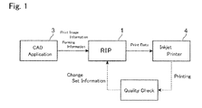
- Fig. 1 is a view showing a printing system in which an RIP in accordance with this embodiment is used
- Fig. 2 is a function block diagram of an RIP in accordance with this embodiment.
- an RIP 1 in accordance with this embodiment is physically or logically connected with a CAD application 3 and an inkjet printer 4.
- the CAD application 3 is a drawing application which is built in a personal computer or the like.
- the CAD application 3 prepares forming information for forming and bending a film and print image information for printing on the film.
- the forming information includes three-dimensional figure information, two-dimensional figure information or the like.
- the forming information includes a positional coordinate of a vertex of a bent part and a bending angle of the bent part as the information regarding to the bent part of the film.
- the CAD application 3 transmits the forming information and the print image information which have been prepared to the RIP 1.
- the inkjet printer 4 prints an image on the surface of the film as a print medium by means of that ink droplets of one or plural colors are ejected from an inkjet head not shown.
- the RIP 1 acquires the forming information and the print image information transmitted from the CAD application 3 and performs the acquired print image information with density adjustment and the like to prepare print data, which are transmitted to the inkjet printer 4.
- the RIP 1 is provided with functions of a print image information acquiring part 11, a forming information acquiring part 12, a vertex detecting part 13, a bending angle detecting part 14 and a print density adjusting part 15.
- the print image information acquiring part 11 acquires print image information which is transmitted from the CAD application 3.
- the forming information acquiring part 12 acquires forming information which is transmitted from the CAD application 3.
- the vertex detecting part 13 detects a vertex of a bent part where the film is bent on the basis of the forming information acquired in the forming information acquiring part 12. In other words, the vertex detecting part 13 searches for a bent part from a figure information when the forming information is a three-dimensional figure information and, when the forming information is a two-dimensional figure information, the vertex detecting part 13 searches for a bent part on the basis of a bending information which has been added to the figure information or a bending line on a plane.
- the vertex detecting part 13 detects an angular part as a vertex when the searched bent part is bent in an angular shape and, when the searched bent part is bent in a curved shape, an arc center of the curved face is detected as a vertex.
- the bending angle detecting part 14 detects a bending angle of a vertex which has been detected in the vertex detecting part 13 on the basis of the forming information acquired in the forming information acquiring part 12. In other words, the bending angle detecting part 14 calculates a bending angle of the bent part on the basis of the figure information when the forming information is a three-dimensional figure information and, when the forming information is a two-dimensional figure information, the bending angle detecting part 14 calculates a bending angle of the bent part on the basis of a bending angle information or the like which has been added to the figure information.
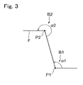
- Fig. 3 is an explanatory view showing a vertex and a bending angle.
- the vertex detecting part 13 detects points “P1” and “P2” as vertexes.
- the bending angle detecting part 14 detects angles “ ⁇ 1” and “ ⁇ 2” around the vertexes "P1” and “P2” as the bending angles of the bent parts "B1" and “B2".
- the bending angle " ⁇ 1" of the bent part “B1” is smaller than 180° and thus the bent part “B1” is judged to be bent in a recessed shape and, since the bending angle " ⁇ 2" of the bent part “B2" is larger than 180°, the bent part “B2" is judged to be bent in a projected shape.
- the print density adjusting part 15 adjusts print density of the print image information which has been acquired in the print image information acquiring part 11 on the basis of the vertex "P" detected in the vertex detecting part 13 and the bending angle " ⁇ " detected in the bending angle detecting part 14. In other words, the print density adjusting part 15 adjusts the print density of the print image information depending on a distance from the vertex "P" and the bending angle " ⁇ ".
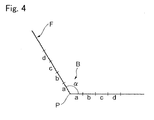
- Fig. 4 is an explanatory view showing a distance from the vertex in the bent part.
- the bent part "B” is bent with the bending angle " ⁇ " and with the vertex "P" as the center. Regions of "a”, “b”, “c” and “d” are set from the vertex “P” in this order and the regions approach to the vertex “P” in the order of "d", “c", "b” and "a”.
- the print density adjusting part 15 sets the print density of the print image information to be lowered as approaching to the vertex "P" when the bent part "B” is bent in a recessed shape and, on the contrary, when the bent part "B” is bent in a projected shape, the print density of the print image information is set to be heightened as approaching to the vertex "P".
- the print density adjusting part 15 manages a print density setting table for setting the print density.
- Fig. 5 shows a print density setting table in a bent part which is formed in a recessed shape
- Fig. 6 shows a print density setting table in a bent part which is formed in a projected shape.
- the print density setting tables shown in Figs. 5 and 6 are tables in which a color printing with the use of cyan "C", magenta "M” and yellow “Y" is performed by the inkjet printer 4 and the total density and density ratios of the respective colors are set in the print density setting table.
- a plurality of print density setting tables is provided for respective predetermined ranges of the bending angle " ⁇ ".
- the print density setting table shown in Fig. 5 is correspondent to the bent part "B" formed in a recessed shape and thus the densities are set so as to be lowered as approaching to the vertex "P".
- the total density is lowered as 100% ⁇ 80% ⁇ 60% ⁇ 40% in the order from the positions "d" through “a”.
- the inks of respective colors are set as approaching to the vertex "P” so that the cyan "C” is lowered as 20% ⁇ 16% ⁇ 12% ⁇ 8%, the magenta “M” is lowered as 30% ⁇ 24% ⁇ 18% ⁇ 12%, and the yellow “Y” is lowered as 50% ⁇ 40% ⁇ 30% ⁇ 20%.
- the print density table shown in Fig. 6 is correspondent to the bent part "B" formed in a projected shape and thus the densities are set so as to be heightened as approaching to the vertex "P".
- the total density is set to be heightened as 100% ⁇ 120% ⁇ 140% ⁇ 160% in the order from the positions "d" through "a".
- the inks of respective colors are set as approaching to the vertex "P" so that the cyan “C” is set to be heightened as 20% ⁇ 24% ⁇ 28% ⁇ 32%, the magenta “M” is set to be heightened as 30% ⁇ 36% ⁇ 42% ⁇ 48%, and the yellow “Y” is set to be heightened as 50% ⁇ 60% ⁇ 70% ⁇ 80%.
- the total densities and the density ratios of the inks of the respective colors shown in Figs. 5 and 6 are only examples and may be appropriately set depending on the kinds of ink and various conditions. Further, the print density setting table is also capable of being appropriately changed through an operation of an operator or the like.
- the print density adjusting part 15 refers to the print density setting tables shown in Figs. 5 and 6 and changes the print density of the print image information to a print density on the basis of the bending angle " ⁇ " of the bent part "B" and the distance from the vertex "P". In other words, the print density adjusting part 15 changes ejection density of ink droplets ejected from the inkjet printer 4 and adjusts the print density to prepare print data which are transmitted to the inkjet printer 4.
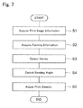
- Fig. 7 is a flow chart showing a processing operation of the RIP.
- the operation of the RIP 1 described below is executed according to a program recorded in a storage device such as a ROM by means of that a processing part (not shown) structured of CPU or the like integrally manages the functions such as the print image information acquiring part 11, the forming information acquiring part 12, the vertex detecting part 13, the bending angle detecting part 14 and the print density adjusting part 15.
- the RIP 1 acquires print image information which is transmitted from the CAD application 3 (step S1).
- the RIP 1 acquires forming information which is transmitted from the CAD application 3 (step S2).
- the RIP 1 detects a bent part "B" of the film "F” on the basis of the forming information which has been acquired in the step S2 to detect a vertex "P" of the bent part "B” (step S3).
- the RIP 1 detects a bending angle " ⁇ " of the bent part "B" which has been detected in the step S3 on the basis of the forming information which has been acquired in the step S2 (step S4).
- the RIP 1 adjusts a print density of the print image information which has been acquired in the step S1 on the basis of the vertex "P" detected in the step S3 and the bending angle " ⁇ " detected in the step S4 (step S5).
- adjustment of the print density is executed with reference to the print density setting table so that the print density is set to be lowered as approaching to the vertex "P" in the bent part "B” formed in a recessed shape and the print density is set to be heightened as approaching to the vertex "P" in the bent part “B” formed in a projected shape.
- an ejection density of ink droplets which are to be ejected from the inkjet printer 4 is calculated depending on the print density which has been set, and print data are created by using the calculated result and transmitted to the inkjet printer 4.
- an ink ejection control is executed on the basis of the print data which have been transmitted from the RIP 1 and ink droplets are ejected on the film "F" to print an image.
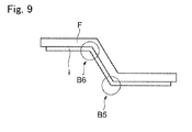
- Figs. 8 and 9 are cross-sectional views showing films which have been bent in a projected and recessed shape.
- an ink layer "i” made of ink droplets which have been ejected from the inkjet printer 4 is formed on a front face of the film "F".
- the film “F” is formed to be bent from its front face side by the forming equipment and a bent part "B3" formed in a recessed shape and a bent part "B4" formed in a projected shape are formed in the film "F".
- a bent part "B3" formed in a recessed shape and a bent part "B4" formed in a projected shape
- an ink layer "i” made of ink droplets which have been ejected from the inkjet printer 4 is formed on a rear face of the film "F". Also, the film “F” is formed to be bent from its front face side by the forming equipment and a bent part "B5" formed in a projected shape and a bent part “B6" formed in a recessed shape are formed in the film "F".
- an operator for the RIP 1 checks quality of the image printed on the film "F".
- the quality check is especially performed on the quality of the print image around the bent part of the film “F”.
- the print images around the bent parts "B3" through “B6" shown in Figs. 8 and 9 are observed and checked by the operator whether floating or cracking is occurred in the ink layer “i” or not, whether the ink layer “i” is separated from or not, or whether the print density is uniform or not, and so forth.
- the operator changes the respective density set values in the print density setting table which is managed in the RIP 1.
- the processing from the step S1 is repeated again and an image is printed on the film "F".
- the print image information is adjusted to the optimum print density corresponding to expansion and contraction of the ink layer "i", which will be occurred when the film "F” is bent in a projected and recessed shape, by means of that the print density of the print image information is adjusted on the basis of the vertex "P" and the bending angle " ⁇ ". In this manner, the quality degradation of the image which is printed on the film "F” to be bent is restrained.
- the print density variation around the bent part "B” is gradated by means of that the print density is adjusted depending on the distance from the vertex "P" and thus the print density can be made uniform.
- the print density around the bent part "B” can be made uniform by bending of the film “F” in the recessed shape and floating of the ink layer “i” and separation of the ink layer “i” can be restrained.
- the print density around the bent part "B” can be made uniform by bending of the film “F” in the projected shape and cracking of the ink layer “i” can be restrained.
- an interval of ink droplets can be varied by changing the ejection density of the ink droplets as the adjusting means of the print density. Therefore, even when the film "F" is bent in a projected and recessed shape, interference between the ink droplets can be suppressed to a minimum and destruction of the ink layer "i" due to the interference between the ink droplets can be restrained.
- the print density of the print image information is adjusted by referring to the print density management table.
- the print density of the print image information may be adjusted by calculating the optimum print density through a predetermined arithmetic expression.
- the quality check of the image which has been printed on the film "F” is performed through observation by an operator.
- the quality check of the image may be performed such that the image printed on the film "F” is image-pickuped by a monitor or the like and density variation or the like of the image having been image-pickuped is analyzed by a computer or the like and, on the basis of the analyzed result, the print density management table or the predetermined arithmetic expression is changed automatically.
- the present invention may be applicable to an RIP.
Landscapes
- Engineering & Computer Science (AREA)
- Multimedia (AREA)
- Signal Processing (AREA)
- Manufacturing & Machinery (AREA)
- Ink Jet (AREA)
Abstract
Description
- The present invention relates to a print density adjusting device, a print density adjusting method and a print density adjusting program, with which printing is performed by an inkjet printer on a medium that is to be bent later.
- A membrane switch has been commonly utilized as a switch for an electric apparatus or the like. The membrane switch is formed so that, after a switch image or the like has been printed on a sheet-shaped film by an inkjet printer, the film is bent in a recessed and projected shape (see, for example,
Patent Literatures 1 and 2). -
- [PTL 1] Japanese Patent Laid-Open No.
Hei 09-193368 - [PTL 2] Japanese Patent Laid-Open No.
2008-126505 - However, in a conventional inkjet printer, printing is performed only on a medium which has been already bent in a projected and recessed shape. Therefore, when printing is performed on a medium like a membrane switch which will be bent in a projected and recessed shape in a subsequent process, ink layer located on the bent portion is expanded or contracted and deteriorated by bending of the medium in the recessed and projected shape. In other words, in the bent part which is bent in a projected shape, the ink layer is expanded and thus its print density is lowered and a crack may be occurred in the ink layer. On the other hand, in the bent part which is bent in a recessed shape, the ink layer is contracted and thus the ink layer may be floated and separated.
- In view of the problems described above, an objective of the present invention is to provide a print density adjusting device, a print density adjusting method and a print density adjusting program which are capable of restraining deterioration of an ink layer which is printed on a medium formed in a projected and recessed shape.
- The present invention provides a print density adjusting device of print image information for printing with an inkjet printer on a medium which is to be bent, including a print image information acquiring means which acquires the print image information, a forming information acquiring means which acquires forming information of the medium, a vertex detecting means which detects a vertex of a bent part which is to be bent on the basis of the forming information, a bending angle detecting means which detects a bending angle of the bent part on the basis of the forming information, and a print density adjusting means which adjusts print density of the print image information which is acquired by the print image information acquiring means on the basis of the vertex detected by the vertex detecting means and the bending angle detected by the bending angle detecting means.
- According to the print density adjusting device in accordance with the present invention, a vertex and its bending angle to be bent are detected by acquiring the forming information of a medium in addition to print image information. In addition, since print density of the print image information is adjusted on the basis of the vertex and the bending angle, the print image information can be adjusted to the optimum print density corresponding to expansion and contraction of the ink layer which will be occurred when the medium is bent in a projected and recessed shape. Therefore, the quality degradation of the image which is printed on the medium to be bent is restrained.
- In this case, it is preferable that the print density adjusting means adjusts the print density of the print image information depending on a distance from the vertex. According to this print density adjusting device, in consideration of that the ink layer is gradually expanded or contracted with the vertex of the bent part as a center, the print density variation around the bent part is gradated by means of that the print density is adjusted depending on the distance from the vertex. Therefore, the print density can be made uniform.
- Further, it is preferable that, when the bent part is to be bent in a recessed shape, the print density adjusting means sets the print density to be lowered as approaching to the vertex of the bent part. According to this print density adjusting device, in consideration of that the ink layer is contracted at the bent part which is formed in a recessed shape, the print density is lowered as approaching to the vertex. As a result, the print density around the bent part can be made uniform by bending of the medium in the recessed shape and floating of the ink layer and separation of the ink layer can be restrained.
- On the other hand, it is preferable that, when the bent part is to be bent in a projected shape, the print density adjusting means sets the print density to be heightened as approaching to the vertex of the bent part. According to this print density adjusting device, in consideration of that the ink layer is expanded in the bent part which is formed in a projected shape, the print density is heightened as approaching to the vertex and thus the print density around the bent part can be made uniform by bending of the medium in the projected shape and cracking of the ink layer can be restrained.
- Further, it is preferable that the print density adjusting means adjusts the print density of the print image information by varying ejection density of ink droplets which are ejected from the inkjet printer. According to this print density adjusting device, an interval of ink droplets is capable of being varied by changing the ejection density of the ink droplets as the adjusting means of the print density. Therefore, even when the medium is bent in a projected and recessed shape, interference between the ink droplets can be suppressed to a minimum and thus destruction of the ink layer due to the interference between the ink droplets can be restrained.
- The present invention further provides a print density adjusting method of print image information for printing with an inkjet printer on a medium which is to be bent, including a print image information acquiring step in which print image information is acquired, a forming information acquiring step in which forming information of the medium is acquired, a vertex detecting step in which a vertex of a bent part which is to be bent is detected on the basis of the forming information, a bending angle detecting step in which a bending angle of the bent part is detected on the basis of the forming information, and a print density adjusting step in which print density of the print image information acquired in the print image information acquiring step is adjusted on the basis of the vertex detected in the vertex detecting step and the bending angle detected in the bending angle detecting step.
- According to the print density adjusting method in accordance with the present invention, a vertex and its bending angle to be bent are detected by acquiring the forming information of a medium in addition to print image information. In addition, since print density of the print image information is adjusted on the basis of the vertex and the bending angle, the print image information can be adjusted in the optimum print density corresponding to the expansion and contraction of the ink layer which will be occurred when the medium is bent in a projected and recessed shape. In this manner, quality degradation of the image which is printed on the medium to be bent is restrained.
- The present invention further provides a print density adjusting program of print image information for printing with an inkjet printer on a medium which is to be bent and the print density adjusting program is executed by a computer. In this case, the print density adjusting program includes a print image information acquiring step in which print image information is acquired, a forming information acquiring step in which forming information of the medium is acquired, a vertex detecting step in which a vertex of a bent part which is to be bent is detected on the basis of the forming information, a bending angle detecting step in which a bending angle of the bent part is detected on the basis of the forming information, and a print density adjusting step in which print density of the print image information acquired by the print image information acquiring step is adjusted on the basis of the vertex detected in the vertex detecting step and the bending angle detected in the bending angle detecting step.
- According to the print density adjusting program in accordance with the present invention, a step is provided in which the forming information of a medium is acquired in addition to the print image information and thus a vertex and its bending angle to be bent are detected. In addition, a step is provided in which the print density of the print image information is adjusted on the basis of the vertex and the bending angle and thus the print image information can be adjusted in the optimum print density corresponding to the expansion and contraction of the ink layer which will be occurred when the medium is bent in a projected and recessed shape. In this manner, the quality degradation of the image which is printed on the medium to be bent is restrained.
- According to the present invention, the quality degradation of the image which is printed on the medium to be bent is restrained.
-
- [
Fig. 1 ]
Fig. 1 is a view showing a printing system in which an RIP is used in accordance with an embodiment of the present invention. - [
Fig. 2 ]
Fig. 2 is a function block diagram showing an RIP in accordance with an embodiment of the present invention. - [
Fig. 3 ]
Fig. 3 is an explanatory view showing a vertex and a bending angle. - [
Fig. 4 ]
Fig. 4 is an explanatory view showing a distance from a vertex in a bent part. - [
Fig. 5 ]
Fig. 5 shows a print density setting table in a bent part which is formed in a recessed shape. - [
Fig. 6 ]
Fig. 6 is a print density setting table in a bent part which is formed in a projected shape. - [
Fig. 7 ]
Fig. 7 is a flow chart showing a processing operation of an RIP. - [
Fig. 8 ]
Fig. 8 is a cross-sectional view showing a film which is bent in a projected and recessed shape. - [
Fig. 9 ]
Fig. 9 is a cross-sectional view showing a film which is bent in a projected and recessed shape. - A print density adjusting device, a print density adjusting method and a print density adjusting program in accordance with a preferred embodiment of the present invention will be described in detail below with reference to the accompanying drawings. In the present embodiment, a print density adjusting device and a print density adjusting method in the present invention are realized in an RIP (Raster Image Processor). An RIP in accordance with this embodiment is a processor in which a print density of print image data is adjusted for printing on a medium such as a membrane switch which will be bent in a projected and recessed shape in a subsequent process. A membrane switch is a well-known switch, which is structured so that a resin film or the like formed in a projected shape is disposed on a contact point. In all drawings, the same reference signs are used for the same portions or the corresponding portions.
-
Fig. 1 is a view showing a printing system in which an RIP in accordance with this embodiment is used, andFig. 2 is a function block diagram of an RIP in accordance with this embodiment. As shown inFig. 1 , anRIP 1 in accordance with this embodiment is physically or logically connected with aCAD application 3 and aninkjet printer 4. - The
CAD application 3 is a drawing application which is built in a personal computer or the like. TheCAD application 3 prepares forming information for forming and bending a film and print image information for printing on the film. The forming information includes three-dimensional figure information, two-dimensional figure information or the like. In addition, the forming information includes a positional coordinate of a vertex of a bent part and a bending angle of the bent part as the information regarding to the bent part of the film. Further, theCAD application 3 transmits the forming information and the print image information which have been prepared to theRIP 1. - The
inkjet printer 4 prints an image on the surface of the film as a print medium by means of that ink droplets of one or plural colors are ejected from an inkjet head not shown. - The
RIP 1 acquires the forming information and the print image information transmitted from theCAD application 3 and performs the acquired print image information with density adjustment and the like to prepare print data, which are transmitted to theinkjet printer 4. In order to perform this operation, theRIP 1 is provided with functions of a print imageinformation acquiring part 11, a forminginformation acquiring part 12, avertex detecting part 13, a bendingangle detecting part 14 and a printdensity adjusting part 15. - The print image
information acquiring part 11 acquires print image information which is transmitted from theCAD application 3. - The forming
information acquiring part 12 acquires forming information which is transmitted from theCAD application 3. - The
vertex detecting part 13 detects a vertex of a bent part where the film is bent on the basis of the forming information acquired in the forminginformation acquiring part 12. In other words, thevertex detecting part 13 searches for a bent part from a figure information when the forming information is a three-dimensional figure information and, when the forming information is a two-dimensional figure information, thevertex detecting part 13 searches for a bent part on the basis of a bending information which has been added to the figure information or a bending line on a plane. Thevertex detecting part 13 detects an angular part as a vertex when the searched bent part is bent in an angular shape and, when the searched bent part is bent in a curved shape, an arc center of the curved face is detected as a vertex. - The bending
angle detecting part 14 detects a bending angle of a vertex which has been detected in thevertex detecting part 13 on the basis of the forming information acquired in the forminginformation acquiring part 12. In other words, the bendingangle detecting part 14 calculates a bending angle of the bent part on the basis of the figure information when the forming information is a three-dimensional figure information and, when the forming information is a two-dimensional figure information, the bendingangle detecting part 14 calculates a bending angle of the bent part on the basis of a bending angle information or the like which has been added to the figure information. -
Fig. 3 is an explanatory view showing a vertex and a bending angle. As shown inFig. 3 , when a film "F" is to be bent at bent parts "B1" and "B2", thevertex detecting part 13 detects points "P1" and "P2" as vertexes. Further, the bendingangle detecting part 14 detects angles "α1" and "α2" around the vertexes "P1" and "P2" as the bending angles of the bent parts "B1" and "B2". The bending angle "α1" of the bent part "B1" is smaller than 180° and thus the bent part "B1" is judged to be bent in a recessed shape and, since the bending angle "α2" of the bent part "B2" is larger than 180°, the bent part "B2" is judged to be bent in a projected shape. - The print
density adjusting part 15 adjusts print density of the print image information which has been acquired in the print imageinformation acquiring part 11 on the basis of the vertex "P" detected in thevertex detecting part 13 and the bending angle "α" detected in the bendingangle detecting part 14. In other words, the printdensity adjusting part 15 adjusts the print density of the print image information depending on a distance from the vertex "P" and the bending angle "α". -
Fig. 4 is an explanatory view showing a distance from the vertex in the bent part. InFig. 4 , the bent part "B" is bent with the bending angle "α" and with the vertex "P" as the center. Regions of "a", "b", "c" and "d" are set from the vertex "P" in this order and the regions approach to the vertex "P" in the order of "d", "c", "b" and "a". The printdensity adjusting part 15 sets the print density of the print image information to be lowered as approaching to the vertex "P" when the bent part "B" is bent in a recessed shape and, on the contrary, when the bent part "B" is bent in a projected shape, the print density of the print image information is set to be heightened as approaching to the vertex "P". - Specifically, the print
density adjusting part 15 manages a print density setting table for setting the print density.Fig. 5 shows a print density setting table in a bent part which is formed in a recessed shape andFig. 6 shows a print density setting table in a bent part which is formed in a projected shape. The print density setting tables shown inFigs. 5 and6 are tables in which a color printing with the use of cyan "C", magenta "M" and yellow "Y" is performed by theinkjet printer 4 and the total density and density ratios of the respective colors are set in the print density setting table. In this embodiment, a plurality of print density setting tables is provided for respective predetermined ranges of the bending angle "α". - The print density setting table shown in
Fig. 5 is correspondent to the bent part "B" formed in a recessed shape and thus the densities are set so as to be lowered as approaching to the vertex "P". In other words, the total density is lowered as 100% → 80% → 60% → 40% in the order from the positions "d" through "a". Further, the inks of respective colors are set as approaching to the vertex "P" so that the cyan "C" is lowered as 20% → 16% → 12% → 8%, the magenta "M" is lowered as 30% → 24% → 18% → 12%, and the yellow "Y" is lowered as 50% → 40% → 30% → 20%. - On the other hand, the print density table shown in
Fig. 6 is correspondent to the bent part "B" formed in a projected shape and thus the densities are set so as to be heightened as approaching to the vertex "P". In other words, the total density is set to be heightened as 100% → 120% → 140% → 160% in the order from the positions "d" through "a". Further, the inks of respective colors are set as approaching to the vertex "P" so that the cyan "C" is set to be heightened as 20% → 24% → 28% → 32%, the magenta "M" is set to be heightened as 30% → 36% → 42% → 48%, and the yellow "Y" is set to be heightened as 50% → 60% → 70% → 80%. - The total densities and the density ratios of the inks of the respective colors shown in
Figs. 5 and6 are only examples and may be appropriately set depending on the kinds of ink and various conditions. Further, the print density setting table is also capable of being appropriately changed through an operation of an operator or the like. - The print
density adjusting part 15 refers to the print density setting tables shown inFigs. 5 and6 and changes the print density of the print image information to a print density on the basis of the bending angle "α" of the bent part "B" and the distance from the vertex "P". In other words, the printdensity adjusting part 15 changes ejection density of ink droplets ejected from theinkjet printer 4 and adjusts the print density to prepare print data which are transmitted to theinkjet printer 4. - Next, an operation of the
RIP 1 in accordance with this embodiment will be described below with reference toFig. 7. Fig. 7 is a flow chart showing a processing operation of the RIP. In this embodiment, the operation of theRIP 1 described below is executed according to a program recorded in a storage device such as a ROM by means of that a processing part (not shown) structured of CPU or the like integrally manages the functions such as the print imageinformation acquiring part 11, the forminginformation acquiring part 12, thevertex detecting part 13, the bendingangle detecting part 14 and the printdensity adjusting part 15. - First, the
RIP 1 acquires print image information which is transmitted from the CAD application 3 (step S1). - Further, the
RIP 1 acquires forming information which is transmitted from the CAD application 3 (step S2). - Next, the
RIP 1 detects a bent part "B" of the film "F" on the basis of the forming information which has been acquired in the step S2 to detect a vertex "P" of the bent part "B" (step S3). - Further, the
RIP 1 detects a bending angle "α" of the bent part "B" which has been detected in the step S3 on the basis of the forming information which has been acquired in the step S2 (step S4). - Next, the
RIP 1 adjusts a print density of the print image information which has been acquired in the step S1 on the basis of the vertex "P" detected in the step S3 and the bending angle "α" detected in the step S4 (step S5). As described above, adjustment of the print density is executed with reference to the print density setting table so that the print density is set to be lowered as approaching to the vertex "P" in the bent part "B" formed in a recessed shape and the print density is set to be heightened as approaching to the vertex "P" in the bent part "B" formed in a projected shape. Further, in the step S5, an ejection density of ink droplets which are to be ejected from theinkjet printer 4 is calculated depending on the print density which has been set, and print data are created by using the calculated result and transmitted to theinkjet printer 4. - In the
inkjet printer 4, an ink ejection control is executed on the basis of the print data which have been transmitted from theRIP 1 and ink droplets are ejected on the film "F" to print an image. - The film "F" on which the image has been printed is bent by a forming equipment not shown in a projected and recessed shape.
Figs. 8 and9 are cross-sectional views showing films which have been bent in a projected and recessed shape. In the film "F" shown inFig. 8 , an ink layer "i" made of ink droplets which have been ejected from theinkjet printer 4 is formed on a front face of the film "F". Also, the film "F" is formed to be bent from its front face side by the forming equipment and a bent part "B3" formed in a recessed shape and a bent part "B4" formed in a projected shape are formed in the film "F". On the other hand, in the film "F" shown inFig. 9 , an ink layer "i" made of ink droplets which have been ejected from theinkjet printer 4 is formed on a rear face of the film "F". Also, the film "F" is formed to be bent from its front face side by the forming equipment and a bent part "B5" formed in a projected shape and a bent part "B6" formed in a recessed shape are formed in the film "F". - When the film "F" has been bent as described above, as shown in
Fig. 1 , an operator for theRIP 1 checks quality of the image printed on the film "F". The quality check is especially performed on the quality of the print image around the bent part of the film "F". Specifically, the print images around the bent parts "B3" through "B6" shown inFigs. 8 and9 are observed and checked by the operator whether floating or cracking is occurred in the ink layer "i" or not, whether the ink layer "i" is separated from or not, or whether the print density is uniform or not, and so forth. When judged that these check items are not satisfied, the operator changes the respective density set values in the print density setting table which is managed in theRIP 1. When the print density setting table in theRIP 1 has been changed, the processing from the step S1 is repeated again and an image is printed on the film "F". - As described above, according to this embodiment, in addition to the print image information, the forming information for the film "F" is acquired and thus the vertex "P" and the bending angle "α" where the film "F" is to be bent are detected. Therefore, the print image information is adjusted to the optimum print density corresponding to expansion and contraction of the ink layer "i", which will be occurred when the film "F" is bent in a projected and recessed shape, by means of that the print density of the print image information is adjusted on the basis of the vertex "P" and the bending angle "α". In this manner, the quality degradation of the image which is printed on the film "F" to be bent is restrained.
- Further, in consideration of that the ink layer "i" is gradually expanded and contracted with the vertex "P" of the bent part "B" as a center, the print density variation around the bent part "B" is gradated by means of that the print density is adjusted depending on the distance from the vertex "P" and thus the print density can be made uniform.
- In this case, in consideration of that the ink layer "i" is contracted at the bent part "B" which is formed in a recessed shape, the print density is lowered as approaching to the vertex "P". Therefore, the print density around the bent part "B" can be made uniform by bending of the film "F" in the recessed shape and floating of the ink layer "i" and separation of the ink layer "i" can be restrained.
- On the other hand, in consideration of that the ink layer "i" is expanded at the bent part "B" which is formed in a projected shape, the print density is heightened as approaching to the vertex "P". Therefore, the print density around the bent part "B" can be made uniform by bending of the film "F" in the projected shape and cracking of the ink layer "i" can be restrained.
- Further, an interval of ink droplets can be varied by changing the ejection density of the ink droplets as the adjusting means of the print density. Therefore, even when the film "F" is bent in a projected and recessed shape, interference between the ink droplets can be suppressed to a minimum and destruction of the ink layer "i" due to the interference between the ink droplets can be restrained.
- Although the present invention has been shown and described with reference to a specific embodiment, the present invention is not limited to this embodiment. For example, in the embodiment described above, the print density of the print image information is adjusted by referring to the print density management table. However, for example, the print density of the print image information may be adjusted by calculating the optimum print density through a predetermined arithmetic expression.
- Further, in the embodiment described above, the quality check of the image which has been printed on the film "F" is performed through observation by an operator. However, for example, the quality check of the image may be performed such that the image printed on the film "F" is image-pickuped by a monitor or the like and density variation or the like of the image having been image-pickuped is analyzed by a computer or the like and, on the basis of the analyzed result, the print density management table or the predetermined arithmetic expression is changed automatically.
- The present invention may be applicable to an RIP.
- 1 ... RIP, 11 ... print image information acquiring part, 12 ... forming information acquiring part, 13 ... vertex detecting part, 14 ... bending angle detecting part, 15 ... print density adjusting part, 3 ... CAD application, 4 ... inkjet printer, "F" ... film (medium), "P" ... vertex, "α" ... bending angle, "B1" through "B4" ... bent part, "i" ... ink layer.
Claims (7)
- A print density adjusting device of print image information for printing with an inkjet printer on a medium which is to be bent, comprising:a print image information acquiring means which acquires the print image information;a forming information acquiring means which acquires forming information of the medium;a vertex detecting means which detects a vertex of a bent part which is to be bent on a basis of the forming information;a bending angle detecting means which detects a bending angle of the bent part on the basis of the forming information; anda print density adjusting means which adjusts print density of the print image information which is acquired in the print image information acquiring means on a basis of the vertex detected in the vertex detecting means and the bending angle detected in the bending angle detecting means.
- The print density adjusting device according to claim 1, wherein the print density adjusting means adjusts the print density of the print image information depending on a distance from the vertex.
- The print density adjusting device according to claim 2, wherein when the bent part is to be bent in a recessed shape, the print density adjusting means sets the print density to be lowered as approaching to the vertex of the bent part.
- The print density adjusting device according to claim 2 or 3, wherein when the bent part is to be bent in a projected shape, the print density adjusting means sets the print density to be heightened as approaching to the vertex of the bent part.
- The print density adjusting device according to one of claims 1 through 4, wherein the print density adjusting means adjusts the print density of the print image information by varying ejection density of ink droplets which are ejected from the inkjet printer.
- A print density adjusting method of print image information for printing with an inkjet printer on a medium which is to be bent, comprising:a print image information acquiring step in which print image information is acquired;a forming information acquiring step in which forming information of the medium is acquired;a vertex detecting step in which a vertex of a bent part which is to be bent is detected on a basis of the forming information;a bending angle detecting step in which a bending angle of the bent part is detected on the basis of the forming information; anda print density adjusting step in which print density of the print image information acquired in the print image information acquiring step is adjusted on a basis of the vertex detected in the vertex detecting step and the bending angle detected in the bending angle detecting step.
- A print density adjusting program of print image information for printing with an inkjet printer on a medium which is to be bent, the print density adjusting program being executed by a computer and the print density adjusting program comprising:a print image information acquiring step in which print image information is acquired;a forming information acquiring step in which forming information of the medium is acquired;a vertex detecting step in which a vertex of a bent part which is to be bent is detected on a basis of the forming information;a bending angle detecting step in which a bending angle of the bent part is detected on the basis of the forming information; anda print density adjusting step in which print density of the print image information acquired in the print image information acquiring step is adjusted on a basis of the vertex detected in the vertex detecting step and the bending angle detected in the bending angle detecting step.
Applications Claiming Priority (2)
| Application Number | Priority Date | Filing Date | Title |
|---|---|---|---|
| JP2008298239A JP4456648B1 (en) | 2008-11-21 | 2008-11-21 | Print density adjustment apparatus, print density adjustment method, and print density adjustment program |
| PCT/JP2009/069620 WO2010058814A1 (en) | 2008-11-21 | 2009-11-19 | Printing density adjusting apparatus, printing density adjusting method and printing density adjusting program |
Publications (2)
| Publication Number | Publication Date |
|---|---|
| EP2277706A1 true EP2277706A1 (en) | 2011-01-26 |
| EP2277706A4 EP2277706A4 (en) | 2017-04-05 |
Family
ID=42198253
Family Applications (1)
| Application Number | Title | Priority Date | Filing Date |
|---|---|---|---|
| EP09827595.1A Withdrawn EP2277706A4 (en) | 2008-11-21 | 2009-11-19 | Printing density adjusting apparatus, printing density adjusting method and printing density adjusting program |
Country Status (6)
| Country | Link |
|---|---|
| US (1) | US8079658B2 (en) |
| EP (1) | EP2277706A4 (en) |
| JP (1) | JP4456648B1 (en) |
| KR (1) | KR101180070B1 (en) |
| CN (1) | CN102015310B (en) |
| WO (1) | WO2010058814A1 (en) |
Families Citing this family (11)
| Publication number | Priority date | Publication date | Assignee | Title |
|---|---|---|---|---|
| US9061521B2 (en) * | 2010-09-22 | 2015-06-23 | 3Dphotoworks Llc | Method and apparatus for three-dimensional digital printing |
| JP5541105B2 (en) * | 2010-11-16 | 2014-07-09 | セイコーエプソン株式会社 | Printing method |
| JP5625920B2 (en) * | 2011-01-06 | 2014-11-19 | セイコーエプソン株式会社 | Image processing apparatus, image processing method, and program thereof |
| JP5760469B2 (en) * | 2011-02-07 | 2015-08-12 | セイコーエプソン株式会社 | Image processing apparatus and image processing method |
| JP5772097B2 (en) * | 2011-03-14 | 2015-09-02 | セイコーエプソン株式会社 | Image processing apparatus and image processing method |
| EP3230076B1 (en) | 2014-12-11 | 2019-09-11 | Hewlett-Packard Development Company, L.P. | A printer comprising a bend sensor |
| US10265951B2 (en) * | 2016-06-29 | 2019-04-23 | Canon Kabushiki Kaisha | Inkjet printing apparatus and control method |
| EP3809255A1 (en) * | 2019-10-16 | 2021-04-21 | Heidelberger Druckmaschinen AG | Special rasterizing pattern at folding edge |
| JP7629723B2 (en) * | 2020-12-11 | 2025-02-14 | ローランドディー.ジー.株式会社 | Printer |
| GB2604399A (en) * | 2021-03-05 | 2022-09-07 | Domino Uk Ltd | Shrink film colour adjustment |
| CN113467728B (en) * | 2021-09-02 | 2021-11-16 | 深圳市汉森软件有限公司 | Cloud printing method, device, equipment and storage medium |
Family Cites Families (16)
| Publication number | Priority date | Publication date | Assignee | Title |
|---|---|---|---|---|
| JP2752898B2 (en) * | 1993-06-16 | 1998-05-18 | 株式会社小松製作所 | Springback angle measuring device in V-bending |
| JPH08189592A (en) * | 1995-01-11 | 1996-07-23 | Koyo Seiko Co Ltd | Metallic bending pipe |
| JPH09193368A (en) | 1996-01-12 | 1997-07-29 | Canon Inc | INK JET PRINTING APPARATUS AND INK JET PRINTING METHOD |
| JP2000051951A (en) * | 1998-08-10 | 2000-02-22 | Amada Denshi:Kk | Bending machine, method and device for bend angle measuring in bending machine |
| US6330019B1 (en) * | 1998-11-13 | 2001-12-11 | Matsushita Graphic Communication Systems, Inc. | Image recording apparatus and optical recording head |
| JP3887516B2 (en) * | 1999-12-28 | 2007-02-28 | 株式会社フジシールインターナショナル | Heat shrink label continuum |
| CN1223981C (en) * | 2000-02-01 | 2005-10-19 | 匹克托罗杰克公司 | Method and apparatus for quantizing a color image through a single dither matrix |
| JP4077661B2 (en) * | 2002-05-31 | 2008-04-16 | ポリマテック株式会社 | Membrane switch and method for forming membrane switch operation sheet |
| EP1679191B1 (en) * | 2003-10-31 | 2011-04-20 | Seiko Epson Corporation | Printing method and printing system |
| JP2005199625A (en) * | 2004-01-16 | 2005-07-28 | Dainippon Printing Co Ltd | Method for manufacturing in-mold decoration film |
| JP2006209427A (en) * | 2005-01-27 | 2006-08-10 | Konica Minolta Medical & Graphic Inc | Image output controller and image output system |
| JP4533805B2 (en) * | 2005-06-06 | 2010-09-01 | 株式会社ミマキエンジニアリング | Inkjet printer for 3D media printing and printing method using the same |
| JP4989886B2 (en) * | 2005-12-21 | 2012-08-01 | 有限会社ペイントスタッフ | Method for manufacturing an object having an inorganic coating film |
| KR20080012643A (en) * | 2006-08-04 | 2008-02-12 | 삼성전자주식회사 | Image forming apparatus having an array head cartridge |
| JP5116289B2 (en) * | 2006-11-20 | 2013-01-09 | 株式会社フオトクラフト社 | Method and apparatus for printing on uneven printing surface |
| JP2008310123A (en) * | 2007-06-15 | 2008-12-25 | Canon Inc | Image forming apparatus and image forming method |
-
2008
- 2008-11-21 JP JP2008298239A patent/JP4456648B1/en not_active Expired - Fee Related
-
2009
- 2009-11-19 KR KR1020107024055A patent/KR101180070B1/en not_active Expired - Fee Related
- 2009-11-19 WO PCT/JP2009/069620 patent/WO2010058814A1/en not_active Ceased
- 2009-11-19 EP EP09827595.1A patent/EP2277706A4/en not_active Withdrawn
- 2009-11-19 CN CN2009801155454A patent/CN102015310B/en not_active Expired - Fee Related
-
2010
- 2010-10-08 US US12/900,786 patent/US8079658B2/en not_active Expired - Fee Related
Also Published As
| Publication number | Publication date |
|---|---|
| CN102015310B (en) | 2013-04-24 |
| EP2277706A4 (en) | 2017-04-05 |
| JP4456648B1 (en) | 2010-04-28 |
| US8079658B2 (en) | 2011-12-20 |
| CN102015310A (en) | 2011-04-13 |
| KR20100136525A (en) | 2010-12-28 |
| KR101180070B1 (en) | 2012-09-06 |
| JP2010120342A (en) | 2010-06-03 |
| US20110074853A1 (en) | 2011-03-31 |
| WO2010058814A1 (en) | 2010-05-27 |
Similar Documents
| Publication | Publication Date | Title |
|---|---|---|
| US8079658B2 (en) | Print density adjusting device, print density adjusting method and print density adjusting program | |
| EP3305532B1 (en) | Image inspection device, image inspection method, program, and ink jet printing system | |
| US8562099B2 (en) | Ink jet recording apparatus and method for detecting faulty discharge in ink jet recording apparatus | |
| US8851618B2 (en) | Inkjet printing apparatus and inkjet printing method | |
| EP3228465B1 (en) | Method and apparatus for detecting streak, and printing apparatus | |
| US20180236799A1 (en) | Test pattern creation method, test pattern, printing apparatus, and program | |
| US20100315459A1 (en) | Method for printing on a curved surface | |
| JP6945060B2 (en) | Image forming device and method, abnormality nozzle detection method, and printed matter manufacturing method | |
| US9792514B2 (en) | Image inspection method and apparatus, and ink jet printing apparatus | |
| JP5482626B2 (en) | Printing system, correspondence information creation method | |
| US11318753B2 (en) | Control device and control method | |
| US9162496B2 (en) | Printing method and printing apparatus | |
| CN102016785A (en) | Print data generating device, print data generating method, and print data generating program | |
| JP5916531B2 (en) | Image recording apparatus, ejection failure detection method, test chart creation method, and test chart data generation program | |
| US9227424B1 (en) | System and method for missing ejector correction for half-toned images in three-dimensional object printing by adding drops in other layers | |
| US8814301B2 (en) | Printing apparatus and printing method | |
| US10661587B2 (en) | Test pattern creation method, test pattern, printing apparatus, and program | |
| JP2012226322A5 (en) | ||
| US20140354721A1 (en) | Printing apparatus, printing medium, and printing method | |
| US20160031249A1 (en) | Printing apparatus and printing method | |
| US8777358B2 (en) | Inkjet printer | |
| JP2007230090A (en) | Recorder | |
| US20250074071A1 (en) | Printing apparatus and print control method | |
| JP2023020130A (en) | Recording device, control method, and program | |
| JP2023020131A (en) | Recording device, control method, and program |
Legal Events
| Date | Code | Title | Description |
|---|---|---|---|
| PUAI | Public reference made under article 153(3) epc to a published international application that has entered the european phase |
Free format text: ORIGINAL CODE: 0009012 |
|
| 17P | Request for examination filed |
Effective date: 20101110 |
|
| AK | Designated contracting states |
Kind code of ref document: A1 Designated state(s): AT BE BG CH CY CZ DE DK EE ES FI FR GB GR HR HU IE IS IT LI LT LU LV MC MK MT NL NO PL PT RO SE SI SK SM TR |
|
| AX | Request for extension of the european patent |
Extension state: AL BA RS |
|
| DAX | Request for extension of the european patent (deleted) | ||
| STAA | Information on the status of an ep patent application or granted ep patent |
Free format text: STATUS: THE APPLICATION HAS BEEN WITHDRAWN |
|
| RA4 | Supplementary search report drawn up and despatched (corrected) |
Effective date: 20170303 |
|
| RIC1 | Information provided on ipc code assigned before grant |
Ipc: B41J 2/01 20060101AFI20170227BHEP |
|
| 18W | Application withdrawn |
Effective date: 20170303 |