EP2277629A1 - Disposable container for paint fluid and method for producing such a disposable container - Google Patents
Disposable container for paint fluid and method for producing such a disposable container Download PDFInfo
- Publication number
- EP2277629A1 EP2277629A1 EP09169523A EP09169523A EP2277629A1 EP 2277629 A1 EP2277629 A1 EP 2277629A1 EP 09169523 A EP09169523 A EP 09169523A EP 09169523 A EP09169523 A EP 09169523A EP 2277629 A1 EP2277629 A1 EP 2277629A1
- Authority
- EP
- European Patent Office
- Prior art keywords
- container
- attachment
- disposable
- storage volume
- disposable container
- Prior art date
- Legal status (The legal status is an assumption and is not a legal conclusion. Google has not performed a legal analysis and makes no representation as to the accuracy of the status listed.)
- Withdrawn
Links
Images

Classifications
-
- B—PERFORMING OPERATIONS; TRANSPORTING
- B05—SPRAYING OR ATOMISING IN GENERAL; APPLYING FLUENT MATERIALS TO SURFACES, IN GENERAL
- B05B—SPRAYING APPARATUS; ATOMISING APPARATUS; NOZZLES
- B05B9/00—Spraying apparatus for discharge of liquids or other fluent material, without essentially mixing with gas or vapour
- B05B9/03—Spraying apparatus for discharge of liquids or other fluent material, without essentially mixing with gas or vapour characterised by means for supplying liquid or other fluent material
- B05B9/04—Spraying apparatus for discharge of liquids or other fluent material, without essentially mixing with gas or vapour characterised by means for supplying liquid or other fluent material with pressurised or compressible container; with pump
- B05B9/08—Apparatus to be carried on or by a person, e.g. of knapsack type
- B05B9/0805—Apparatus to be carried on or by a person, e.g. of knapsack type comprising a pressurised or compressible container for liquid or other fluent material
- B05B9/0833—Apparatus to be carried on or by a person, e.g. of knapsack type comprising a pressurised or compressible container for liquid or other fluent material comprising a compressed gas container, e.g. a nitrogen cartridge
Definitions
- the invention relates to a disposable container for color fluid, in particular for receiving and applying a color fluid by spraying, a method for producing a disposable colored container and the use of such a container for paint, varnish, glaze, wood preservatives or similar fluids.
- Disposable color containers are known from the prior art, for example in the form of aerosol spray cans.
- a color fluid and a pressurized propellant container are arranged in the can.
- a dispensing valve is provided, upon which actuation by the propellant pressurized color fluid can be sprayed via a spray nozzle provided on the valve.
- the entire aerosol can is handled to disperse the color fluid onto a surface or object as desired.
- Such aerosol cans are therefore limited to sizes or filling volumes between usually 250 ml and 1000 ml. In larger aerosol aerosol cans, the handling is adversely affected or even impossible. If a user wants to apply a correspondingly large amount of paint, he is forced to use several such aerosol spray cans, which leads to an increased incidence of deflated spray cans that must be disposed of or recycled under appropriate environmental impact.
- known aerosol spray cans have the disadvantage that they must be held and operated at the same time in one hand, which is ergonomically unfavorable and tiring especially for larger amounts of color fluid to be applied.
- the present invention seeks to provide a disposable container for color fluid, in particular for receiving and applying a color fluid by spraying, which is easy to handle even with large container sizes, especially in a range between 1 to 20 liters can be transported, with which even large amounts of paint can be sprayed in an ergonomic manner, can be stored in the color fluid in particular after a partial consumption for long periods without loss of quality and which is finally good disposal or recyclable. Furthermore, the object of the invention is to provide a method with which such a disposable container can be produced.
- a disposable container for color fluid in particular for receiving and applying color fluid by spraying, with a storage volume for color fluid forming container with container bottom and container wall, wherein the container is closed with an essay on the essay with a propellant reservoir connectable pressure control unit is arranged, with which a propellant in the storage volume can be introduced to adjust therein a regulated overpressure to the environment, and wherein on the attachment a hose is arranged, via which a spray device, in particular spray gun is connected to the storage volume.
- the spray device and the container forming the storage volume for color fluid are not formed as a unit to be handled together when spraying colored fluid.
- the use of a spray device connected to the container via a hose opens up the possibility of providing containers for large quantities of color fluid as disposable containers, whereby during the spraying of colored fluid the container can be placed on the floor or a corresponding surface and only the spraying device independent of the container and its weight can be easily operated and handled.
- spraying the color fluid it is not necessary to move the entire container with the color fluid received therein, which considerably simplifies the spraying and dispensing.
- the handling and operation of a not directly on the container arranged spray device, eg. B. in the form of a spray gun is compared to a handling and operation of an aerosol spray can ergonomically favorable and therefore longer feasible operation, so that correspondingly large amount of paint can be applied under less stress and fatigue.
- the spray device may be formed independently of the shape, size and material of the container. It can therefore be adapted to the anatomy of the hand with greater freedom of design. It is preferably designed as an injection-molded part, so that it can be inexpensively and easily manufactured in the appropriate form with low weight.
- the container according to the invention is designed as a disposable container, it is inexpensive to manufacture and disposable compared to reusable Farbsprüh- or Lackiersystemen. Thus, even for occasional users the use of a Farbsprühsystems at relatively low cost possible. Especially It is advantageous that a cleaning, as is necessary in professional Mehrweglackiersystemen eliminated, and the disposable container after emptying completely disposed of or can be recycled.
- the disposable container is advantageously made of easily disposable or recyclable materials.
- the container made of metal, preferably made of tinplate or aluminum sheet.
- Such containers are well known from overpressure applications of the beverage industry and have excellent resistance to optionally reactive liquids and good handling and storage. Furthermore, they are well suited for recycling and have with correspondingly low weight excellent stability.
- the article may advantageously be designed as a plastic component, in particular as a plastic injection molded component according to another proposal.
- Plastic is also good as a recycling material.
- the plastic attachment in almost any shapes can be produced inexpensively, with particular advantage, the pressure control unit can be used in the form of a common plastic assembly.
- the article is arranged according to a further proposal of the invention by the end user substantially insoluble on the container.
- the attachment with locking elements for example in the form of a clip connection, may be fastened to the container rim.
- attachment by gluing, welding, soldering or similar types of attachment is possible.
- the container edge is formed bead-shaped or provided with a fold. At this bead or fold the article can be defined outwardly or inwardly across by means of locking projections or clips.
- Another way to set the attachment to the container is that on the opposite side of the container bottom of the container wall, a container lid is provided.
- the container lid can be formed integrally with the container wall or arranged pressure-tight as a separate element on this in a known manner.
- the container lid is made of the same material as the rest of the container. It may be provided in the middle of a filling opening in the container lid, through which the storage volume filled on the one hand with color fluid and on the other hand color fluid can be removed from the storage volume.
- This filling opening can now be used with particular advantage to the essay solely or in addition to the above-mentioned attachment to the edge of the container in the same or similar manner on the container set.
- a riser pipe is arranged on the attachment, which protrudes into the storage volume. It can be glued, stuck, screwed or otherwise connected to the essay or be integrally formed with this.
- the riser is fluidly connected tightly to the hose and serves to receive color fluid from a region as close to the bottom of the container and to promote via the hose to the spray device.
- the container bottom is curved, so that the center or edge of a deepest point of the container is formed.
- the riser ends preferably in this lowest point or in its vicinity, so that an almost complete emptying of the disposable container is possible.
- the riser pipe projects through the filling opening into the storage volume.
- a separate opening in the container for the riser is also possible to provide a separate opening in the container for the riser.
- the arrangement of the riser in the filling opening allows with particular advantage that only an opening for filling and emptying is provided in the container and only this is an opening to seal fluid and pressure-tight.
- a sealing plug preferably made of rubber, can be arranged, which seals the space between riser pipe and opening edge in a fluid-tight and pressure-tight manner. It is particularly useful in terms of manufacturing, when the sealing plug is fixedly arranged on the riser pipe or connected thereto.
- the sealing plug can be glued to the riser pipe or molded onto it.
- the riser pipe can be arranged sealingly in the container opening together with the sealing plug in one operation.
- the sealing plug can initially be arranged in the container opening in the intended manner and, where appropriate, held there by positive locking, adhesion, molding or gluing. In this case, the riser is introduced when arranging the attachment in the sealing plug and possibly glued.
- the riser in addition to the promotion of the color fluid from the container at the same time fulfills the further function of feeding the propellant into the storage volume.
- This is supplied via the pressure control device to the storage volume, wherein the Examsch barnlass in the storage volume can basically be designed in any way.
- the riser used for the supply of propellant this advantageously no further passages and seals in the container or in the essay provided.
- the cap closing the container fulfills, in addition to its function as a closure of the container, at the same time further tasks. So he may according to a further proposal of the invention some or all necessary for a removal of the color fluid units such as pressure control unit, propellant reservoir, riser, hose, spray gun and optionally provided safety and shut-off valves.
- the basic shape of the attachment corresponds to the basic shape of the container.
- the attachment has an essentially circular basic shape. Its lower edge preferably has a slightly larger diameter than the edge of the container on which the attachment is arranged, so that the attachment is the container edge encompassing on or on the container anordbar.
- the attachment is designed so that it forms the disposable container in a well stackable and manageable shape together with the container.
- the attachment may be shaped so that the entire disposable container has a cylindrical or barrel-shaped shape.
- the overall shape of the disposable container formed from container and attachment then contributes to a good stackability.
- the attachment can have a recess or groove on the outside or inside. Preferably, this extends around the tower in an annular manner.
- the width and depth of the groove are preferably matched to the length of the hose between sprayer and attachment, so that the hose can be rolled up in the recess or groove to save space and largely protected from damage.
- a receptacle is formed in or on the attachment, in which the spray device can be preferably held by clamping or positive engagement or by releasable retaining means, so they also safe and protected against damage and incorrect operation can be arranged on the attachment.
- one or more handles are provided on the essay.
- the handles are formed on the side facing away from the container or end face of the attachment.
- An embodiment of the handle in the form of circular segment-like handles is Particularly preferred, since such handles can form an at least partially circumferential boundary on the side facing away from the container of the essay.
- the pressure regulating unit is arranged in a region bounded outwardly from the attachment or within the attachment. It is particularly advantageous if other functional units of the disposable package are also arranged within this area of the attachment.
- the outwardly limited area may be formed by the attachment itself, for example, by its handle and the structure containing the recess or groove for the tube. The functional units of the disposable package arranged within the area are protected against damage by the structure of the attachment.
- the handle / handles are / are arranged in a circular or circular segment parallel to the container bottom, so that the basic structure of the disposable container consisting of attachment and container is essentially cylindrical, so that disposable containers according to the invention are particularly easy to stack, store and transport.
- CO 2 cartridge as propellant reservoir has been found to be particularly advantageous.
- the amount of CO 2 contained in the cartridge depends essentially on the internal pressure of the container required for spraying the color fluid and the container volume. Particularly advantageous is the use of a commercially available 38g CO 2 cartridge together with a 5 liter container. Depending on the spray nozzle used, a container internal pressure between 2.0 bar and 3 bar, preferably 2.5 bar has been found to be particularly advantageous. At a pressure of 2.5 bar, 5 liters of color fluid can be sprayed by means of a commercially available 38 g CO 2 cartridge. However, these values may vary depending on the color fluid.
- a color fluid in the context of the present invention, in particular paints, varnishes, wood preservatives, oils, or similar liquids are to be understood, which must be spread as evenly distributed by means of the spray nozzle.
- spray pressure, nozzle size and viscosity of the color fluid to be sprayed must be coordinated.
- other blowing agents can be used instead of CO 2 . Examples include nitrogen (N 2 ) or nitrous oxide (laughing gas, N 2 O).
- the invention further proposes a method for producing a disposable color thread.
- the method is used in particular for the production of the above-described disposable ink pack in its various embodiments.
- a container is provided which has a filling opening, for example by merely consisting of the container bottom and container wall or additionally provided with a container lid having a filling opening.
- the container can be produced as a semi-finished product by means of known production methods and can advantageously be used as such semifinished product, e.g. be provided to a paint manufacturing company.
- the container is filled via the filling opening in a known manner with color fluid.
- the filling can be done by means of conventional filling either with the container in an upright position or by means of a filling lance.
- the attachment is also advantageously designed as a semi-finished product and preferably provided with all the functional units that are necessary for the operation of the disposable Farbgebindes.
- a pressure-regulating unit which can be connected to a propellant reservoir or is already connected, with which a propellant can be introduced into the storage volume of the container in order to set therein a regulated overpressure relative to the environment, is arranged on the attachment as semifinished product.
- a hose is further arranged on the attachment, which in turn is connected at its opposite end of the essay with a spray device.
- the attachment is formed as all functional units already exhibiting semi-finished, since then filled with color fluid container must be closed only by proper arrangement of the essay in the production of disposable ink container and no further steps after filling are necessary.
- the attachment is provided in one embodiment with locking elements, in particular in the form of a clip connection and can be securely and permanently attached to the container and pressing particularly easy during assembly of the disposable ink container. It is particularly advantageous when sealing means used to seal the filling opening of the container are necessary, are already pre-assembled or molded to the essay, so that prior to mounting the attachment to the container no further steps are required, and arranging, attaching and sealing of the attachment to the container can be performed in one operation.
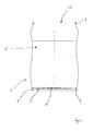
- FIG. 1 a container 2 for the disposable container 1 in a first embodiment without mounted attachment 3 is shown.
- the container 2 has a substantially circular container bottom 4 and a container wall 5 connected thereto.
- the container bottom 4 is curved in its inner region in the direction of the container interior.
- the outer edge 6 of the container bottom 4 in this way forms an annular standing area, on which the disposable container 1 can be set up safely and stably.
- the outer edge 6 has a folded outwardly and in the direction of the container wall 5 fold 7, in which the outer edge 6 of the bottom 4 is received fluid and pressure-tight.
- a container lid 10 is disposed on the container bottom 4 opposite side of the container wall 5.
- the container lid 10 is curved in its inner region as well as the container bottom 4 in the direction of the container interior, so that a peripheral lid edge 11 is formed. This is similar to the container bottom 4 with the upper fold 9 of the container wall 5 by a flange fluid and pressure-tight manner.
- the peripheral lid edge 11 forms a base, on which the container 2 can be turned off and stored as a semi-finished product or for a filling by means of filling lance.
- the shape of the container bottom 4 and the outer edge 6 are adapted to the shape of the container lid 10 and the lid edge 11, so that container bottom 4 and container lid 10 of two successive Stacked container 2 into each other and partly can grip around each other, so that the container 2 as a semi-finished are particularly good stackable, storable and transportable.
- a filling opening 13 is provided centrally.
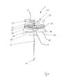
- the attachment 3 for the disposable container 1 is shown separately in a schematic side view in FIG. 3 shown.
- the attachment 3 has a base body 14. This is at the intended arrangement of the article 3 the container 2 facing side corresponding to the shape of the container, for example, circular and has an annular end edge 15 whose inner diameter is slightly larger than the outer diameter of the upper lid edge 11, so that he the container 2 can embrace.
- the annular end edge 15 is seated on a disc-shaped cover portion 16, in the middle of the filling opening 13 is provided.
- hook-like locking elements 17 are provided which project from the lid portion 16 in the direction of the container 2 and, as from FIG. 4 can be seen, engage around the cover rim 11 at a proper arrangement of the article 3 on the container 2.
- a riser 18 is provided, which is either formed directly on the lid portion 16 or sealingly connected thereto.
- the length of the riser 18 is dimensioned such that its open lower riser end 19 terminates in a trough-like depression 20 of the container bottom 4. In this way, it is ensured that color fluid received via the riser 18 in the container 2 can be removed substantially completely and without residue.
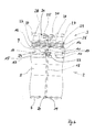
- FIG. 4 shows the disposable container 1 with in FIG. 2 illustrated variant of the container 2 with container lid 10 and filling opening 13.
- the riser 18 is passed through the filling opening 13.
- the seal between riser 18 and container lid 10 via a introduced into the filling opening 13 and the riser 18 fluidly and pressure-tight surrounding plug 23.
- attachment of the attachment 3 takes place on the container 2 via the lid edge 11 and the upper fold 9 encompassing locking elements 17th
- the riser 18 opens into a tube 24. This connects the riser 18 with a spray gun 25. From the container interior via the riser 18 sucked Color fluid is passed through the tube 24 to the spray gun 25.
- the tube 24 is wound in a recess 26 formed on the outside of the attachment 3 for transport and storage purposes and can be unwound for spraying the color fluid.
- two opposing and ring-segment-like handles 27 are formed.
- the facing away from the container 2 end faces 28 of the handle 27 are formed flat and parallel to the outer edge 6 level, so that several disposable containers 1 are stacked one above the other by a disposable container is placed on another disposable container, the outer edge 6 of the upper disposable container, the handles 27th can embrace the lower disposable container, so that a particularly stable state is possible.
- FIG. 4 shows that the spray gun 25 in this inner region 21 can be arranged and durable by means of a clamping device, not shown.
- a CO 2 print cartridge 29 filled with 38g CO 2 as blowing agent is indicated.
- the CO 2 print cartridge 29 is a in the Figures 3 and 4 only schematically indicated pressure control valve 30 connected to the container interior. Via the pressure control valve 30 it is achieved that during a removal of the color fluid in the interior of the container 2 continuously the desired pressure prevails, so that a uniform spray result can be achieved up to a complete emptying of the disposable container 1.
- the spray gun 25 is formed in the form of a plastic injection molded component as a disposable spray gun. It has a non-illustrated in the figures and actuated by a handle shut-off valve. For spraying of recorded in the container 2 color fluid, the container interior is acted upon via the pressure control valve unit 30 with CO 2 as blowing agent from the CO 2 -Printpatrone 29, so that the desired and largely constant internal pressure is ensured for the removal.
- the shut-off valve is opened by actuating the spray gun 25, color fluid contained in the container 2 under overpressure is sprayed out through the riser pipe 18, the hose 24 and the spray gun 25.
Landscapes
- Containers And Packaging Bodies Having A Special Means To Remove Contents (AREA)
Abstract
Description
Die Erfindung betrifft ein Einweggebinde für Farbfluid, insbesondere zum Aufnehmen und Ausbringen eines Farbfluids durch Versprühen, ein Verfahren zum Herstellen eines Einwegfarbgebindes sowie die Verwendung eines solchen Gebindes für Farbe, Lack, Lasur, Holzschutzmittel oder ähnliche Fluide.The invention relates to a disposable container for color fluid, in particular for receiving and applying a color fluid by spraying, a method for producing a disposable colored container and the use of such a container for paint, varnish, glaze, wood preservatives or similar fluids.
Einwegfarbgebinde sind aus dem Stand der Technik bekannt, beispielsweise in Form von Aerosol-Sprühdosen. Bei diesen sind ein Farbfluid sowie ein unter Druck stehender Treibmittelbehälter in der Dose angeordnet. An der Dosenoberseite ist ein Ausgabeventil vorgesehen, bei dessen Betätigung durch das Treibmittel unter Druck gesetztes Farbfluid über eine an dem Ventil vorgesehene Sprühdüse versprüht werden kann.Disposable color containers are known from the prior art, for example in the form of aerosol spray cans. In these, a color fluid and a pressurized propellant container are arranged in the can. At the top of the can, a dispensing valve is provided, upon which actuation by the propellant pressurized color fluid can be sprayed via a spray nozzle provided on the valve.
Beim Versprühen des Farbfluids wird die gesamte Aerosol-Dose gehandhabt, um das Farbfluid in gewünschter Weise auf eine Fläche oder einen Gegenstand auszubringen. Solche Aerosol-Dosen sind daher auf Größen bzw. Füllvolumina zwischen üblicherweise 250 ml und 1000 ml beschränkt. Bei Aerosol-Sprühdosen größeren Inhalts ist die Handhabbarkeit in nachteiliger Weise verschlechtert oder gar unmöglich. Möchte ein Nutzer eine entsprechend große Farbmenge ausbringen, ist er gezwungen, mehrere solcher Aerosol-Sprühdosen zu verwenden, was zu einem erhöhten Anfall entleerter Sprühdosen führt, die unter entsprechender Umweltbelastung entsorgt oder recycelt werden müssen. Des Weiteren beinhalten bekannte Aerosol-Sprühdosen den Nachteil, dass sie gleichzeitig in einer Hand gehalten und betätigt werden müssen, was ergonomisch ungünstig und insbesondere bei größeren auszubringenden Farbfluidmengen ermüdend ist.Upon spraying the color fluid, the entire aerosol can is handled to disperse the color fluid onto a surface or object as desired. Such aerosol cans are therefore limited to sizes or filling volumes between usually 250 ml and 1000 ml. In larger aerosol aerosol cans, the handling is adversely affected or even impossible. If a user wants to apply a correspondingly large amount of paint, he is forced to use several such aerosol spray cans, which leads to an increased incidence of deflated spray cans that must be disposed of or recycled under appropriate environmental impact. Furthermore, known aerosol spray cans have the disadvantage that they must be held and operated at the same time in one hand, which is ergonomically unfavorable and tiring especially for larger amounts of color fluid to be applied.
Ausgehend von dem zuvor beschriebenen Stand der Technik liegt der Erfindung die Aufgabe zugrunde, ein Einweggebinde für Farbfluid, insbesondere zum Aufnehmen und Ausbringen eines Farbfluids mittels Versprühen bereitzustellen, welches auch bei großen Gebindegrößen, insbesondere in einem Bereich zwischen 1 bis 20 Liter, leicht handhabbar und transportierbar ist, mit dem auch große Farbmengen in ergonomischer Weise versprüht werden können, in dem Farbfluid insbesondere auch nach einem Teilverbrauch über längere Zeiträume ohne Qualitätseinbußen gelagert werden kann und welches schließlich gut entsorg- oder recycelbar ist. Des Weiteren liegt der Erfindung die Aufgabe zugrunde, ein Verfahren bereitzustellen, mit dem ein derartiges Einweggebinde erzeugt werden kann.Based on the above-described prior art, the present invention seeks to provide a disposable container for color fluid, in particular for receiving and applying a color fluid by spraying, which is easy to handle even with large container sizes, especially in a range between 1 to 20 liters can be transported, with which even large amounts of paint can be sprayed in an ergonomic manner, can be stored in the color fluid in particular after a partial consumption for long periods without loss of quality and which is finally good disposal or recyclable. Furthermore, the object of the invention is to provide a method with which such a disposable container can be produced.
Vorrichtungsseitig wird die Aufgabe gelöst durch ein Einweggebinde für Farbfluid, insbesondere zum Aufnehmen und Ausbringen von Farbfluid durch Versprühen, mit einem ein Speichervolumen für Farbfluid ausbildenden Behälter mit Behälterboden und Behälterwand, wobei der Behälter mit einem Aufsatz verschlossen ist, an dem Aufsatz eine mit einem Treibmittelreservoir verbindbare Druckregeleinheit angeordnet ist, mit der ein Treibmittel in das Speichervolumen einleitbar ist, um darin einen geregelten Überdruck gegenüber der Umgebung einzustellen, und wobei an dem Aufsatz ein Schlauch angeordnet ist, über den eine Sprühvorrichtung, insbesondere Sprühpistole mit dem Speichervolumen verbunden ist.On the device side, the object is achieved by a disposable container for color fluid, in particular for receiving and applying color fluid by spraying, with a storage volume for color fluid forming container with container bottom and container wall, wherein the container is closed with an essay on the essay with a propellant reservoir connectable pressure control unit is arranged, with which a propellant in the storage volume can be introduced to adjust therein a regulated overpressure to the environment, and wherein on the attachment a hose is arranged, via which a spray device, in particular spray gun is connected to the storage volume.
Erfindungsgemäß sind die Sprühvorrichtung und der das Speichervolumen für Farbfluid ausbildende Behälter nicht als eine beim Versprühen von Farbfluid gemeinsam zu handhabende Einheit ausgebildet. Durch die Verwendung einer über einen Schlauch mit dem Behälter verbundenen Sprühvorrichtung wird die Möglichkeit eröffnet, Behälter für große Farbfluidmengen als Einweggebinde bereitzustellen, wobei während des Versprühens von Farbfluid der Behälter auf dem Boden oder einer entsprechenden Fläche abgestellt werden kann und nur die Sprühvorrichtung unabhängig vom Behälter und dessen Gewicht in einfacher Weise betätigt und gehandhabt werden kann. Beim Versprühen des Farbfluids ist es nicht notwendig, den gesamten Behälter mit dem darin aufgenommenen Farbfluid zu bewegen, was das Versprühen und Ausbringen in erheblicher Weise vereinfacht.According to the invention, the spray device and the container forming the storage volume for color fluid are not formed as a unit to be handled together when spraying colored fluid. The use of a spray device connected to the container via a hose opens up the possibility of providing containers for large quantities of color fluid as disposable containers, whereby during the spraying of colored fluid the container can be placed on the floor or a corresponding surface and only the spraying device independent of the container and its weight can be easily operated and handled. When spraying the color fluid, it is not necessary to move the entire container with the color fluid received therein, which considerably simplifies the spraying and dispensing.
Die Handhabung und Betätigung einer nicht direkt am Behälter angeordneten Sprühvorrichtung, z. B. in Form einer Sprühpistole stellt gegenüber einer Handhabung und Betätigung einer Aerosol-Sprühdose einen ergonomisch günstigeren und daher auch länger durchführbaren Arbeitsvorgang dar, so dass entsprechend große Farbmenge unter geringerer Belastung und Ermüdung ausgebracht werden können. Die Sprühvorrichtung kann unabhängig von Form, Größe und Material des Behälters ausgebildet sein. Sie kann daher mit größerer Gestaltungsfreiheit an die Anatomie der Hand angepasst werden. Sie ist vorzugsweise als Spritzgussteil ausgebildet, so dass sie in der entsprechenden Form mit geringem Gewicht kostengünstig und einfach hergestellt werden kann.The handling and operation of a not directly on the container arranged spray device, eg. B. in the form of a spray gun is compared to a handling and operation of an aerosol spray can ergonomically favorable and therefore longer feasible operation, so that correspondingly large amount of paint can be applied under less stress and fatigue. The spray device may be formed independently of the shape, size and material of the container. It can therefore be adapted to the anatomy of the hand with greater freedom of design. It is preferably designed as an injection-molded part, so that it can be inexpensively and easily manufactured in the appropriate form with low weight.
Da das erfindungsgemäße Gebinde als Einweggebinde konzipiert ist, ist es im Vergleich zu wiedereinsetzbaren Farbsprüh- oder Lackiersystemen kostengünstig herstellbar und vertreibbar. So wird auch für Gelegenheitsanwender die Nutzung eines Farbsprühsystems zu verhältnismäßig günstigen Kosten ermöglicht. Besonders vorteilhaft ist dabei, dass eine Reinigung, wie sie bei professionellen Mehrweglackiersystemen notwendig ist, entfällt und das Einweggebinde nach Entleerung vollständig entsorgt oder einem Recyclingvorgang zugeführt werden kann.Since the container according to the invention is designed as a disposable container, it is inexpensive to manufacture and disposable compared to reusable Farbsprüh- or Lackiersystemen. Thus, even for occasional users the use of a Farbsprühsystems at relatively low cost possible. Especially It is advantageous that a cleaning, as is necessary in professional Mehrweglackiersystemen eliminated, and the disposable container after emptying completely disposed of or can be recycled.
Das Einweggebinde besteht mit Vorteil aus gut entsorg- oder recycelbaren Materialien. Beispielsweise kann der Behälter aus Metall, vorzugsweise aus Weißblech oder Aluminiumblech bestehen. Derartige Behälter sind aus Überdruckanwendungen der Getränkeindustrie hinreichend bekannt und weisen eine ausgezeichnete Beständigkeit gegenüber gegebenenfalls reaktiven Flüssigkeiten sowie eine gute Handhabbarkeit und Lagerbarkeit auf. Des Weiteren sind sie gut für Recycling geeignet und weisen mit entsprechend geringem Gewicht eine ausgezeichnete Stabilität auf.The disposable container is advantageously made of easily disposable or recyclable materials. For example, the container made of metal, preferably made of tinplate or aluminum sheet. Such containers are well known from overpressure applications of the beverage industry and have excellent resistance to optionally reactive liquids and good handling and storage. Furthermore, they are well suited for recycling and have with correspondingly low weight excellent stability.
Der Aufsatz kann gemäß einem weiteren Vorschlag vorteilhaft als Kunststoffbauteil, insbesondere als Kunststoffspritzguss-Bauteil ausgeführt sein. Kunststoff eignet sich ebenfalls gut als Recyclingmaterial. Im Spritzguss ist der Kunststoffaufsatz in nahezu beliebigen Formgebungen kostengünstig herstellbar, wobei mit besonderem Vorteil die Druckregeleinheit in Form einer gängigen Kunststoffbaugruppe verwendet werden kann.The article may advantageously be designed as a plastic component, in particular as a plastic injection molded component according to another proposal. Plastic is also good as a recycling material. In injection molding, the plastic attachment in almost any shapes can be produced inexpensively, with particular advantage, the pressure control unit can be used in the form of a common plastic assembly.
Der Aufsatz ist nach einem weiteren Vorschlag der Erfindung durch den Endverbraucher im Wesentlichen unlösbar am Behälter angeordnet. Auf diese Weise kann die Dichtigkeit, Funktionstüchtigkeit und Sicherheit des Einweggebindes gewahrt werden. Insbesondere kann der Aufsatz mit Rastelementen, beispielsweise in Form einer Clipverbindung, an dem Behälterrand befestigt sein. Zusätzlich oder alternativ ist eine Befestigung mittels Kleben, Schweißen, Löten oder ähnlichen Befestigungsarten möglich. Es ist besonders vorteilhaft, wenn der Behälterrand wulstförmig ausgebildet oder mit einem Falz versehen ist. An diesem Wulst oder Falz kann der Aufsatz nach außen oder nach innen übergreifend mittels Rastvorsprüngen oder Clipsen festgelegt werden. Eine weitere Möglichkeit, den Aufsatz am Behälter festzulegen, besteht darin, dass an der dem Behälterboden gegenüberliegenden Seite der Behälterwand ein Behälterdeckel vorgesehen ist. Der Behälterdeckel kann einteilig mit der Behälterwand ausgebildet oder als separates Element an dieser in bekannter Weise druckdicht angeordnet sein. Vorzugsweise besteht der Behälterdeckel aus dem gleichen Material wie der übrige Behälter. Es kann mittig eine Füllöffnung in dem Behälterdeckel vorgesehen sein, durch die das Speichervolumen einerseits mit Farbfluid befüllt und aus der andererseits Farbfluid aus dem Speichervolumen entnommen werden kann. Diese Füllöffnung kann nun mit besonderem Vorteil verwendet werden, um den Aufsatz ausschließlich oder zusätzlich zu der vorgenannten Befestigung am Behälterrand in gleicher oder ähnlicher Weise am Behälter festzulegen.The article is arranged according to a further proposal of the invention by the end user substantially insoluble on the container. In this way, the tightness, functionality and safety of the disposable container can be maintained. In particular, the attachment with locking elements, for example in the form of a clip connection, may be fastened to the container rim. Additionally or alternatively, attachment by gluing, welding, soldering or similar types of attachment is possible. It is particularly advantageous if the container edge is formed bead-shaped or provided with a fold. At this bead or fold the article can be defined outwardly or inwardly across by means of locking projections or clips. Another way to set the attachment to the container, is that on the opposite side of the container bottom of the container wall, a container lid is provided. The container lid can be formed integrally with the container wall or arranged pressure-tight as a separate element on this in a known manner. Preferably, the container lid is made of the same material as the rest of the container. It may be provided in the middle of a filling opening in the container lid, through which the storage volume filled on the one hand with color fluid and on the other hand color fluid can be removed from the storage volume. This filling opening can now be used with particular advantage to the essay solely or in addition to the above-mentioned attachment to the edge of the container in the same or similar manner on the container set.
In einer weiteren Ausführungsform ist vorgesehen, dass an dem Aufsatz ein Steigrohr angeordnet ist, das in das Speichervolumen hineinragt. Es kann geklebt, gesteckt, geschraubt oder in anderer Weise mit dem Aufsatz verbunden oder einteilig mit diesem ausgebildet sein. Vorzugsweise ist das Steigrohr strömungstechnisch dicht mit dem Schlauch verbunden und dient dazu, Farbfluid aus einem Bereich möglichst nahe am Boden des Behälters aufzunehmen und über den Schlauch zur Sprühvorrichtung zu fördern. Mit besonderem Vorteil ist der Behälterboden gewölbt ausgebildet, so dass mittig oder randseitig ein tiefster Punkt des Behälters ausgebildet wird. Das Steigrohr endet vorzugsweise in diesem tiefsten Punkt oder in dessen Nähe, so dass ein nahezu vollständiges Entleeren des Einweggebindes möglich ist.In a further embodiment it is provided that a riser pipe is arranged on the attachment, which protrudes into the storage volume. It can be glued, stuck, screwed or otherwise connected to the essay or be integrally formed with this. Preferably, the riser is fluidly connected tightly to the hose and serves to receive color fluid from a region as close to the bottom of the container and to promote via the hose to the spray device. With particular advantage, the container bottom is curved, so that the center or edge of a deepest point of the container is formed. The riser ends preferably in this lowest point or in its vicinity, so that an almost complete emptying of the disposable container is possible.
Nach einem weiteren Vorschlag ist vorgesehen, dass das Steigrohr durch die Füllöffnung hindurch in das Speichervolumen ragt. Alternativ ist ebenfalls möglich, für das Steigrohr eine gesonderte Öffnung im Behälter vorzusehen. Die Anordnung des Steigrohrs in der Füllöffnung ermöglicht mit besonderem Vorteil, dass in dem Behälter lediglich eine Öffnung zum Befüllen sowie Entleeren vorgesehen ist und lediglich diese eine Öffnung fluid- und druckdicht abzudichten ist. Zu diesem Zweck kann in der Steigrohröffnung oder Füllöffnung zwischen Steigrohr und dem die Öffnung umgebenden Rand des Behälters ein Dichtstopfen, vorzugsweise aus Gummi, angeordnet sein, der den Zwischenraum zwischen Steigrohr und Öffnungsrand fluid-und druckdicht abdichtet. Es ist fertigungstechnisch besonders sinnvoll, wenn der Dichtstopfen fest an dem Steigrohr angeordnet oder mit diesem verbunden ist. Insbesondere kann der Dichtstopfen mit dem Steigrohr verklebt oder an diesem angeformt sein. So wird ermöglicht, dass bei einer bestimmungsgemäßen Anordnung des Aufsatzes am Behälter das Steigrohr zusammen mit dem Dichtstopfen in einem Arbeitsgang dichtend in der Behälteröffnung angeordnet werden kann. Ebenfalls kann der Dichtstopfen zunächst in bestimmungsgemäßer Weise in der Behälteröffnung angeordnet und dort ggf. durch Formschluss, Kraftschluss, Anformen oder Kleben gehalten sein. In diesem Fall wird das Steigrohr beim Anordnen des Aufsatzes in den Dichtstopfen eingeführt und ggf. verklebt.According to a further proposal, it is provided that the riser pipe projects through the filling opening into the storage volume. Alternatively, it is also possible to provide a separate opening in the container for the riser. The arrangement of the riser in the filling opening allows with particular advantage that only an opening for filling and emptying is provided in the container and only this is an opening to seal fluid and pressure-tight. For this purpose, in the riser opening or filling opening between the riser pipe and the edge of the container surrounding the opening, a sealing plug, preferably made of rubber, can be arranged, which seals the space between riser pipe and opening edge in a fluid-tight and pressure-tight manner. It is particularly useful in terms of manufacturing, when the sealing plug is fixedly arranged on the riser pipe or connected thereto. In particular, the sealing plug can be glued to the riser pipe or molded onto it. This makes it possible that, in a proper arrangement of the attachment to the container, the riser pipe can be arranged sealingly in the container opening together with the sealing plug in one operation. Likewise, the sealing plug can initially be arranged in the container opening in the intended manner and, where appropriate, held there by positive locking, adhesion, molding or gluing. In this case, the riser is introduced when arranging the attachment in the sealing plug and possibly glued.
Mit besonderem Vorteil erfüllt das Steigrohr neben der Förderung des Farbfluids aus dem Behälter heraus gleichzeitig die weitere Funktion einer Zuführung des Treibmittels in das Speichervolumen hinein. Dieses wird über die Druckregeleinrichtung dem Speichervolumen zugeführt, wobei der Treibmitteldurchlass in das Speichervolumen grundsätzlich in beliebiger Weise ausgebildet sein kann. Wird jedoch das Steigrohr für die Zuführung von Treibmittel genutzt, sind hierfür in vorteilhafter Weise keine weiteren Durchlässe und Dichtungen im Behälter oder im Aufsatz vorzusehen.With particular advantage, the riser, in addition to the promotion of the color fluid from the container at the same time fulfills the further function of feeding the propellant into the storage volume. This is supplied via the pressure control device to the storage volume, wherein the Treibmitteldurchlass in the storage volume can basically be designed in any way. However, if the riser used for the supply of propellant, this advantageously no further passages and seals in the container or in the essay provided.
Der den Behälter verschließende Aufsatz erfüllt neben seiner Funktion als Verschluss des Behälters gleichzeitig weitere Aufgaben. So kann er nach einem weiteren Vorschlag der Erfindung einige oder sämtliche für eine Entnahme des Farbfluids notwendige Einheiten wie Druckregeleinheit, Treibmittelreservoir, Steigrohr, Schlauch, Sprühpistole sowie gegebenenfalls vorgesehene Sicherheits- und Absperrventile tragen. Es ist besonders vorteilhaft, wenn die Grundform des Aufsatzes der Grundform des Behälters entspricht. Im Falle eines von der Fertigungstechnik und Logistik besonders günstigen im Wesentlichen zylinderförmigen Behälters besitzt der Aufsatz eine im Wesentlichen kreisförmige Grundform. Sein unterer Rand besitzt vorzugsweise einen leicht größeren Durchmesser als der Rand des Behälters, an dem der Aufsatz angeordnet ist, so dass der Aufsatz den Behälterrand umgreifend auf oder an dem Behälter anordbar ist. Es ist von besonderem Vorteil, wenn der Aufsatz so ausgebildet ist, dass er zusammen mit dem Behälter das Einweggebinde in einer gut stapel- und handhabbaren Gestalt formt. Im Falle eines z.B. zylinder- oder fassförmigen Behälters kann der Aufsatz so geformt sein, dass das gesamte Einweggebinde eine zylinder- oder fassförmige Gestalt besitzt. Die aus Behälter und Aufsatz gebildete Gesamtform des Einweggebindes trägt dann zu einer guten Stapelbarkeit bei. Auf der vom Behälter abgewanden Seite kann der Aufsatz außen- oder innenseitig eine Vertiefung oder Nut aufweisen. Vorzugsweise verläuft diese ringförmig um den Aufsatz herum. Die Breite und Tiefe der Nut sind vorzugsweise auf die Länge des Schlauches zwischen Sprühvorrichtung und Aufsatz abgestimmt, so dass der Schlauch in der Vertiefung oder Nut Platz sparend und weitgehend vor Beschädigungen geschützt aufgerollt werden kann. Es ist besonders vorteilhaft, wenn nach einem weiteren Vorschlag der Erfindung für die am Ende des Schlauches angeordnete Sprühvorrichtung eine Aufnahme im oder am Aufsatz ausgebildet ist, in der die Sprühvorrichtung vorzugsweise durch Klemmen oder Formschluss oder mittels lösbarer Haltemittel gehalten werden kann, so dass sie ebenfalls sicher und vor Beschädigung sowie Fehlbetätigung geschützt am Aufsatz angeordnet werden kann.The cap closing the container fulfills, in addition to its function as a closure of the container, at the same time further tasks. So he may according to a further proposal of the invention some or all necessary for a removal of the color fluid units such as pressure control unit, propellant reservoir, riser, hose, spray gun and optionally provided safety and shut-off valves. It is particularly advantageous if the basic shape of the attachment corresponds to the basic shape of the container. In the case of a substantially cylindrical container which is particularly favorable from production engineering and logistics, the attachment has an essentially circular basic shape. Its lower edge preferably has a slightly larger diameter than the edge of the container on which the attachment is arranged, so that the attachment is the container edge encompassing on or on the container anordbar. It is of particular advantage if the attachment is designed so that it forms the disposable container in a well stackable and manageable shape together with the container. In the case of e.g. cylindrical or barrel-shaped container, the attachment may be shaped so that the entire disposable container has a cylindrical or barrel-shaped shape. The overall shape of the disposable container formed from container and attachment then contributes to a good stackability. On the side turned away from the container, the attachment can have a recess or groove on the outside or inside. Preferably, this extends around the tower in an annular manner. The width and depth of the groove are preferably matched to the length of the hose between sprayer and attachment, so that the hose can be rolled up in the recess or groove to save space and largely protected from damage. It is particularly advantageous if according to a further proposal of the invention for the arranged at the end of the hose sprayer a receptacle is formed in or on the attachment, in which the spray device can be preferably held by clamping or positive engagement or by releasable retaining means, so they also safe and protected against damage and incorrect operation can be arranged on the attachment.
Um den Transport des erfindungsgemäßen Einweggebindes zu erleichtern sowie dessen Handhabbarkeit zu verbessern, wird des Weiteren vorgeschlagen, dass an dem Aufsatz eine oder mehrere Handhaben vorgesehen sind. Vorzugsweise sind die Handhaben an der von dem Behälter abgewandten Seite oder Stirnseite des Aufsatzes ausgebildet. Eine Ausbildung der Handhabe in Form von kreissegmentartigen Griffen ist besonders bevorzugt, da derartige Handhaben eine zumindest bereichsweise umlaufende Begrenzung an der dem Behälter abgewandten Seite des Aufsatzes ausbilden können.In order to facilitate the transport of Einweggebindes invention and to improve its handling, it is further proposed that one or more handles are provided on the essay. Preferably, the handles are formed on the side facing away from the container or end face of the attachment. An embodiment of the handle in the form of circular segment-like handles is Particularly preferred, since such handles can form an at least partially circumferential boundary on the side facing away from the container of the essay.
In einer weiteren Ausführungsform ist die Druckregeleinheit in einem von dem Aufsatz nach außen begrenzten Bereich oder innerhalb des Aufsatzes angeordnet. Es ist besonders vorteilhaft, wenn auch andere Funktionseinheiten des Einweggebindes ebenfalls innerhalb dieses Bereiches des Aufsatzes angeordnet sind. Der nach außen begrenzte Bereich kann durch den Aufsatz selbst ausgebildet sein, beispielsweise durch dessen Handhabe (Handhaben) sowie die die Vertiefung oder Nut für den Schlauch enthaltende Struktur. Die innerhalb des Bereiches angeordneten Funktionseinheiten des Einweggebindes sind durch die Struktur des Aufsatzes geschützt vor Beschädigungen aufgenommen.In a further embodiment, the pressure regulating unit is arranged in a region bounded outwardly from the attachment or within the attachment. It is particularly advantageous if other functional units of the disposable package are also arranged within this area of the attachment. The outwardly limited area may be formed by the attachment itself, for example, by its handle and the structure containing the recess or groove for the tube. The functional units of the disposable package arranged within the area are protected against damage by the structure of the attachment.
Mit besonderem Vorteil ist/sind die Handhabe/Handhaben kreisförmig bzw. kreissegmentförmig parallel zum Behälterboden angeordnet, so dass die Grundstruktur des aus Aufsatz und Behälter bestehenden Einweggebindes im Wesentlichen zylinderförmig ist, so dass erfindungsgemäße Einweggebinde besonders gut stapel- und lagerbar sowie transportfähig sind.The handle / handles are / are arranged in a circular or circular segment parallel to the container bottom, so that the basic structure of the disposable container consisting of attachment and container is essentially cylindrical, so that disposable containers according to the invention are particularly easy to stack, store and transport.
Die Verwendung einer CO2-Patrone als Treibmittelreservoir hat sich als besonders vorteilhaft herausgestellt. Die Menge des in der Patrone enthaltenen CO2 hängt im Wesentlichen vom zum Versprühen des Farbfluids erforderlichen Innendruck des Behälters sowie dem Behältervolumen ab. Besonders vorteilhaft ist die Verwendung einer handelsüblichen 38g CO2-Patrone zusammen mit einem 5 Ltr.-Behälter. In Abhängigkeit von der verwendeten Sprühdüse hat sich ein Behälterinnendruck zwischen 2,0 bar und 3 bar, vorzugsweise von 2,5 bar als besonders vorteilhaft herausgestellt. Bei einem Druck von 2,5 bar sind 5 Ltr. Farbfluid mittels einer handelsüblichen 38g CO2-Patrone versprühbar. Diese Werte können in Abhängigkeit vom Farbfluid jedoch variieren. Unter einem Farbfluid im Sinne der vorliegenden Erfindung sind insbesondere Farben, Lacke, Holzschutzmittel, Öle, oder ähnliche Flüssigkeiten zu verstehen, die mittels der Sprühdüse möglichst gleichmäßig verteilt ausgebracht werden müssen. Es ist anzumerken, dass Sprühdruck, Düsengröße und Viskosität des zu versprühenden Farbfluids aufeinander abgestimmt sein müssen. Je nach Farbfluid können anstelle von CO2 andere Treibmittel verwendet werden. Zu nennen sind hier beispielsweise Stickstoff (N2) oder Distickstoffmonoxid (Lachgas, N2O).The use of a CO 2 cartridge as propellant reservoir has been found to be particularly advantageous. The amount of CO 2 contained in the cartridge depends essentially on the internal pressure of the container required for spraying the color fluid and the container volume. Particularly advantageous is the use of a commercially available 38g CO 2 cartridge together with a 5 liter container. Depending on the spray nozzle used, a container internal pressure between 2.0 bar and 3 bar, preferably 2.5 bar has been found to be particularly advantageous. At a pressure of 2.5 bar, 5 liters of color fluid can be sprayed by means of a commercially available 38 g CO 2 cartridge. However, these values may vary depending on the color fluid. Under a color fluid in the context of the present invention, in particular paints, varnishes, wood preservatives, oils, or similar liquids are to be understood, which must be spread as evenly distributed by means of the spray nozzle. It should be noted that spray pressure, nozzle size and viscosity of the color fluid to be sprayed must be coordinated. Depending on the color fluid, other blowing agents can be used instead of CO 2 . Examples include nitrogen (N 2 ) or nitrous oxide (laughing gas, N 2 O).
Mit der Erfindung wird des Weiteren ein Verfahren zum Herstellen eines Einweg-Farbgewindes vorgeschlagen. Das Verfahren dient insbesondere der Herstellung des vorbeschriebenen Einweg-Farbgebindes in seinen verschiedenen Ausführungsformen. Bei dem Verfahren wird ein Behälter bereitgestellt, der eine Füllöffnung aufweist, beispielsweise indem er lediglich aus Behälterboden und Behälterwand besteht oder zusätzlich mit einem eine Füllöffnung aufweisenden Behälterdeckel versehen ist. In beiden Ausführungsformen ist der Behälter als Halbzeug mittels bekannter Fertigungsverfahren herstellbar und kann in vorteilhafter Weise als solches Halbzeug z.B. einem Farben herstellenden Betrieb zur Verfügung gestellt werden. Der Behälter wird über die Füllöffnung in bekannter Weise mit Farbfluid befüllt. Die Befüllung kann mittels herkömmlicher Abfüllanlagen entweder mit dem Behälter in aufrechter Position oder mittels einer Fülllanze erfolgen. Nach dem Befüllen wird die Füllöffnung dichtend verschlossen. Dazu wird an dem Behälter ein Aufsatz angeordnet und/oder befestigt, wie er im Zusammenhang mit den vorgeschriebenen Einweg-Farbgebinden erläutert wurde. Der Aufsatz ist in vorteilhafter Weise ebenfalls als Halbzeug ausgebildet und vorzugsweise mit sämtlichen Funktionseinheiten versehen, die für den Betrieb des Einweg-Farbgebindes notwendig sind. So ist an dem Aufsatz als Halbzeug beispielsweise eine mit einem Treibmittelreservoir verbindbare oder bereits verbundene Druckregeleinheit angeordnet, mit der ein Treibmittel in das Speichervolumen des Behälters einleitbar ist, um darin einen geregelten Überdruck gegenüber der Umgebung einzustellen. Vorzugsweise ist des Weiteren an dem Aufsatz ein Schlauch angeordnet, der wiederum an seinem dem Aufsatz gegenüberliegenden Ende mit einer Sprühvorrichtung verbunden ist. Es ist besonders vorteilhaft, wenn der Aufsatz als sämtliche Funktionseinheiten bereits aufweisendes Halbzeug ausgebildet ist, da dann bei der Herstellung des Einweg-Farbgebindes der mit Farbfluid befüllte Behälter lediglich durch bestimmungsgemäßes Anordnen des Aufsatzes verschlossen werden muß und keine weiteren Arbeitsschritte nach Befüllung notwendig sind. Es ist jedoch ebenfalls möglich, eine oder mehrere Funktionseinheiten erst nach dem Anordnen des Aufsatzes an dem Behälter zu montieren. Dieses kann beispielsweise beim Treibmittelreservoir sinnvoll sein, da durch ein nicht montiertes Treibmittelreservoir eine Fehlfunktion oder eine übermäßige Druckbeaufschlagung des Behälters nach dem Befüllen und vor der eigentlichen Fluidentnahme unmöglich ist.The invention further proposes a method for producing a disposable color thread. The method is used in particular for the production of the above-described disposable ink pack in its various embodiments. In the method, a container is provided which has a filling opening, for example by merely consisting of the container bottom and container wall or additionally provided with a container lid having a filling opening. In both embodiments, the container can be produced as a semi-finished product by means of known production methods and can advantageously be used as such semifinished product, e.g. be provided to a paint manufacturing company. The container is filled via the filling opening in a known manner with color fluid. The filling can be done by means of conventional filling either with the container in an upright position or by means of a filling lance. After filling, the filling opening is sealed. For this purpose, a cap is arranged and / or fixed to the container, as it has been explained in connection with the prescribed disposable ink containers. The attachment is also advantageously designed as a semi-finished product and preferably provided with all the functional units that are necessary for the operation of the disposable Farbgebindes. For example, a pressure-regulating unit which can be connected to a propellant reservoir or is already connected, with which a propellant can be introduced into the storage volume of the container in order to set therein a regulated overpressure relative to the environment, is arranged on the attachment as semifinished product. Further, a hose is further arranged on the attachment, which in turn is connected at its opposite end of the essay with a spray device. It is particularly advantageous if the attachment is formed as all functional units already exhibiting semi-finished, since then filled with color fluid container must be closed only by proper arrangement of the essay in the production of disposable ink container and no further steps after filling are necessary. However, it is also possible to mount one or more functional units only after arranging the attachment to the container. This can be useful, for example, in the propellant reservoir, as a malfunction or excessive pressurization of the container after filling and before the actual fluid removal is impossible by an unassembled propellant reservoir.
Wie bereits zuvor beschrieben wurde, ist der Aufsatz in einer Ausführungsform mit Rastelementen, insbesondere in Form einer Clip-Verbindung versehen und kann so besonders einfach bei der Montage des Einweg-Farbgebindes durch Aufsetzen auf den Behälter und Andrücken sicher und dauerhaft befestigt werden. Es ist besonders vorteilhaft, wenn Dichtmittel, die zum Abdichten der Füllöffnung des Behälters notwendig sind, bereits an dem Aufsatz vormontiert oder angeformt sind, so dass vor dem Montieren des Aufsatzes am Behälter keine weiteren Arbeitsschritte erforderlich sind, und das Anordnen, Befestigen und Abdichten des Aufsatzes an dem Behälter in einem Arbeitsgang durchgeführt werden kann.As has already been described above, the attachment is provided in one embodiment with locking elements, in particular in the form of a clip connection and can be securely and permanently attached to the container and pressing particularly easy during assembly of the disposable ink container. It is particularly advantageous when sealing means used to seal the filling opening of the container are necessary, are already pre-assembled or molded to the essay, so that prior to mounting the attachment to the container no further steps are required, and arranging, attaching and sealing of the attachment to the container can be performed in one operation.
Weitere Merkmale und Einzelheiten ergeben sich aus der folgenden Beschreibung nicht beschränkender Ausführungsbeispiele anhand der Figuren, in denen zeigt:
- Figur 1
- einen Behälter für das Einweggebinde in einer ersten Ausgestaltung,
-
Figur 2 - einen Behälter für das Einweggebinde in einer zweiten Ausgestaltung,
-
Figur 3 - einen Aufsatz für das Einweggebinde in einer schematischen seitlichen Schnittansicht und
-
Figur 4 - das Einweggebinde im befüllten und fertig montierten Zustand.
- FIG. 1
- a container for the disposable container in a first embodiment,
- FIG. 2
- a container for the disposable container in a second embodiment,
- FIG. 3
- an attachment for the disposable container in a schematic side sectional view and
- FIG. 4
- the disposable container in the filled and fully assembled state.
In der
In der in
Der Aufsatz 3 für das Einweggebinde 1 ist separat in einer schematischen seitlichen Ansicht in
In der Füllöffnung 13 ist ein Steigrohr 18 vorgesehen, das entweder direkt an den Deckelbereich 16 angeformt ist oder dichtend mit diesem verbunden ist. Wie
Wird für das Einweggebinde 1 die in der
Das Steigrohr 18 mündet in einen Schlauch 24. Dieser verbindet das Steigrohr 18 mit einer Sprühpistole 25. Aus dem Behälterinneren über das Steigrohr 18 angesaugtes Farbfluid wird durch den Schlauch 24 zur Sprühpistole 25 geleitet. Der Schlauch 24 ist in einer außenseitig am Aufsatz 3 ausgebildeten Vertiefung 26 zu Transport- und Lagerzwecken aufgewickelt und kann zum Versprühen des Farbfluids abgewickelt werden. An der dem ringförmigen Abschlussrand 15 gegenüberliegenden Seite des Deckelbereiches 16 sind zwei einander gegenüberliegende und ringsegmentartige Handhaben 27 ausgebildet. Die vom Behälter 2 abgewandten Stirnseiten 28 der Handhabe 27 sind flächig und parallel zur Ebene des Außenrandes 6 ausgebildet, so dass mehrere Einweggebinde 1 übereinander stapelbar sind, indem ein Einweggebinde auf ein anderes Einweggebinde aufgesetzt wird, wobei der Außenrand 6 des oberen Einweggebindes die Handhaben 27 des unteren Einweggebindes umgreifen kann, so dass ein besonders stabiler Stand ermöglicht wird.The
In dem von den Handhaben 27, der Vertiefung 26 und dem Deckelbereich 16 umgrenzten Innenbereich 21 des Aufsatzes 3 sind weitere Funktionseinheiten angeordnet.
Die Sprühpistole 25 ist in Form eines Kunststoffspritzgussbauteils als Einwegsprühpistole ausgebildet. Sie weist ein in den Figuren nicht dargestelltes und mittels eines Handgriffs betätigbares Absperrventil auf. Zum Versprühen von im Behälter 2 aufgenommenem Farbfluid wird der Behälterinnenraum über die Druckregelventileinheit 30 mit CO2 als Treibmittel aus der CO2-Druckpatrone 29 beaufschlagt, so dass der gewünschte und weitgehend konstante Innendruck für die Entnahme gewährleistet ist. Bei einem Öffnen des Absperrventils durch Betätigen der Sprühpistole 25 wird in dem Behälter 2 unter Überdruck enthaltenes Farbfluid durch das Steigrohr 18, den Schlauch 24 und die Sprühpistole 25 ausgesprüht.The
- 11
- Einweggebindedisposable containers
- 22
- Behältercontainer
- 33
- Aufsatzessay
- 44
- Behälterbodencontainer bottom
- 55
- Behälterwandcontainer wall
- 66
- Außenrandouter edge
- 77
- Falzfold
- 88th
- 99
- Falz(oben)Fold (above)
- 1010
- Behälterdeckelcontainer lid
- 1111
- Deckelrandcover edge
- 1212
- 1313
- Füllöffnungfill opening
- 1414
- Grundkörperbody
- 1515
- Abschlussrandend edge
- 1616
- Deckelbereichcover region
- 1717
- Rastelementlocking element
- 1818
- Steigrohrriser
- 1919
- SteigrohrendeStandpipe end
- 2020
- muldenartige Vertiefungtrough-like depression
- 2121
- Innenbereichinterior
- 2222
- 2323
- StopfenPlug
- 2424
- Schlauchtube
- 2525
- Sprühpistolespray gun
- 2626
- Vertiefungdeepening
- 2727
- Handhabehandle
- 2828
- Stirnseitefront
- 2929
- CO2-DruckpatroneCO2 cartridge
- 3030
- DruckregelventilPressure control valve
Claims (15)
mit einem ein Speichervolumen für Farbfluid ausbildenden Behälter (2) mit Behälterboden (4) und Behälterwand (5),
wobei der Behälter (2) mit einem Aufsatz (3) verschlossen ist,
wobei an dem Aufsatz (3) eine mit einem Treibmittelreservoir (29) verbindbare Druckregeleinheit (30) angeordnet ist, mit der ein Treibmittel in das Speichervolumen einleitbar ist, um darin einen geregelten Überdruck gegenüber der Umgebung einzustellen,
wobei an dem Aufsatz (3) ein Schlauch (24) angeordnet ist, über den eine Sprühvorrichtung (25) mit dem Speichervolumen verbunden ist. Disposable container (1) for colored fluid, in particular for receiving and applying a colored fluid by spraying,
with a container (2) forming a storage volume for colored fluid with container bottom (4) and container wall (5),
wherein the container (2) is closed with an attachment (3),
wherein on the attachment (3) a with a propellant reservoir (29) connectable pressure control unit (30) is arranged, with a propellant in the storage volume can be introduced to set therein a regulated overpressure to the environment,
wherein on the attachment (3) a hose (24) is arranged, via which a spray device (25) is connected to the storage volume.
Priority Applications (5)
| Application Number | Priority Date | Filing Date | Title |
|---|---|---|---|
| EP09169523A EP2277629A1 (en) | 2009-07-23 | 2009-09-04 | Disposable container for paint fluid and method for producing such a disposable container |
| EP10730814A EP2456566A1 (en) | 2009-07-23 | 2010-07-15 | Disposable container for colored fluid and method for producing such a disposable container |
| PCT/EP2010/060262 WO2011009809A1 (en) | 2009-07-23 | 2010-07-15 | Disposable container for colored fluid and method for producing such a disposable container |
| RU2012100620/05A RU2012100620A (en) | 2009-07-23 | 2010-07-15 | DISPOSABLE CONTAINER FOR COLORED LIQUID AND METHOD FOR PRODUCING SUCH CONTAINER |
| US13/386,664 US20120193451A1 (en) | 2009-07-23 | 2010-07-15 | Disposable container for colored fluid and method for producing such a disposal container |
Applications Claiming Priority (2)
| Application Number | Priority Date | Filing Date | Title |
|---|---|---|---|
| EP09009567 | 2009-07-23 | ||
| EP09169523A EP2277629A1 (en) | 2009-07-23 | 2009-09-04 | Disposable container for paint fluid and method for producing such a disposable container |
Publications (1)
| Publication Number | Publication Date |
|---|---|
| EP2277629A1 true EP2277629A1 (en) | 2011-01-26 |
Family
ID=42245952
Family Applications (2)
| Application Number | Title | Priority Date | Filing Date |
|---|---|---|---|
| EP09169523A Withdrawn EP2277629A1 (en) | 2009-07-23 | 2009-09-04 | Disposable container for paint fluid and method for producing such a disposable container |
| EP10730814A Withdrawn EP2456566A1 (en) | 2009-07-23 | 2010-07-15 | Disposable container for colored fluid and method for producing such a disposable container |
Family Applications After (1)
| Application Number | Title | Priority Date | Filing Date |
|---|---|---|---|
| EP10730814A Withdrawn EP2456566A1 (en) | 2009-07-23 | 2010-07-15 | Disposable container for colored fluid and method for producing such a disposable container |
Country Status (4)
| Country | Link |
|---|---|
| US (1) | US20120193451A1 (en) |
| EP (2) | EP2277629A1 (en) |
| RU (1) | RU2012100620A (en) |
| WO (1) | WO2011009809A1 (en) |
Families Citing this family (1)
| Publication number | Priority date | Publication date | Assignee | Title |
|---|---|---|---|---|
| DE102014223307B4 (en) * | 2014-11-14 | 2020-07-16 | Gema Switzerland Gmbh | Powder container for supplying a spray coating system with coating powder |
Citations (6)
| Publication number | Priority date | Publication date | Assignee | Title |
|---|---|---|---|---|
| GB1196965A (en) * | 1967-09-19 | 1970-07-01 | Nat Can Corp | Attachment for Supplying Gas Pressure to and Dispensing a Product from a Disposable Container |
| AT313780B (en) * | 1970-07-24 | 1974-03-11 | Schmidt Max | Spray bottle or spray can |
| DE9000880U1 (en) * | 1988-11-14 | 1990-03-29 | Prevor International S.A.R.L., Paris, Fr | |
| WO1992019386A1 (en) * | 1991-05-08 | 1992-11-12 | Zeljko Bodulovic | Liquid applicator |
| DE69103126T2 (en) * | 1990-11-09 | 1995-03-23 | Prevor Int | Container for sterile, portable, independent shower and shower equipped with it. |
| US6481642B1 (en) * | 2000-08-28 | 2002-11-19 | Ralph Frank Louis, Jr. | Portable misting apparatus and method for delivering a mist |
-
2009
- 2009-09-04 EP EP09169523A patent/EP2277629A1/en not_active Withdrawn
-
2010
- 2010-07-15 RU RU2012100620/05A patent/RU2012100620A/en not_active Application Discontinuation
- 2010-07-15 US US13/386,664 patent/US20120193451A1/en not_active Abandoned
- 2010-07-15 EP EP10730814A patent/EP2456566A1/en not_active Withdrawn
- 2010-07-15 WO PCT/EP2010/060262 patent/WO2011009809A1/en active Application Filing
Patent Citations (6)
| Publication number | Priority date | Publication date | Assignee | Title |
|---|---|---|---|---|
| GB1196965A (en) * | 1967-09-19 | 1970-07-01 | Nat Can Corp | Attachment for Supplying Gas Pressure to and Dispensing a Product from a Disposable Container |
| AT313780B (en) * | 1970-07-24 | 1974-03-11 | Schmidt Max | Spray bottle or spray can |
| DE9000880U1 (en) * | 1988-11-14 | 1990-03-29 | Prevor International S.A.R.L., Paris, Fr | |
| DE69103126T2 (en) * | 1990-11-09 | 1995-03-23 | Prevor Int | Container for sterile, portable, independent shower and shower equipped with it. |
| WO1992019386A1 (en) * | 1991-05-08 | 1992-11-12 | Zeljko Bodulovic | Liquid applicator |
| US6481642B1 (en) * | 2000-08-28 | 2002-11-19 | Ralph Frank Louis, Jr. | Portable misting apparatus and method for delivering a mist |
Also Published As
| Publication number | Publication date |
|---|---|
| US20120193451A1 (en) | 2012-08-02 |
| EP2456566A1 (en) | 2012-05-30 |
| RU2012100620A (en) | 2013-08-27 |
| WO2011009809A1 (en) | 2011-01-27 |
Similar Documents
| Publication | Publication Date | Title |
|---|---|---|
| EP2490819B1 (en) | Paint container, in particular for paint spray guns | |
| DE60209540T2 (en) | NOZZLE | |
| DE1303782B (en) | ||
| DE19513886A1 (en) | Reusable compressed air aerosol spray | |
| DE3008837C2 (en) | ||
| EP2022751B1 (en) | Tapping device | |
| EP1991469A1 (en) | Arrangement for pouring free-flowing media out of a container | |
| DE102004037448B4 (en) | Paste dispenser with center column | |
| DE2903599C2 (en) | ||
| WO1994006703A1 (en) | Container for storing and transporting pourable media, preferably liquids | |
| EP2277629A1 (en) | Disposable container for paint fluid and method for producing such a disposable container | |
| EP2414103B1 (en) | Disposable container, its utilisation and a method of pressurizing the disposable container | |
| EP3684706A1 (en) | Inliner | |
| EP2328816B1 (en) | Tubular dosing container | |
| DE4327442A1 (en) | Drum, particularly suitable for dispatching chemicals or waste | |
| EP3371068B1 (en) | Single-use beverage barrel made of stainless steel and method of producing the same | |
| DE2127259A1 (en) | CONTAINER OF THE DISPOSABLE TYPE, EQUIPPED WITH A DISPENSER | |
| DE8214181U1 (en) | Accordion-shaped wine container | |
| DE102008056813A1 (en) | Container and method for filling a container | |
| DE4431181C1 (en) | Container for viscous fluids | |
| EP1123252A1 (en) | Closure for the charging hole of a liquid container | |
| DE10326474B4 (en) | pressure vessel | |
| DE1802746A1 (en) | Dispensing device, in particular for aerosols, with a supply pipe running through the propellant container | |
| DE4302446A1 (en) | Refillable aerosol can | |
| DE19940614C2 (en) | Method and device for filling containers for flowable media |
Legal Events
| Date | Code | Title | Description |
|---|---|---|---|
| PUAI | Public reference made under article 153(3) epc to a published international application that has entered the european phase |
Free format text: ORIGINAL CODE: 0009012 |
|
| AK | Designated contracting states |
Kind code of ref document: A1 Designated state(s): AT BE BG CH CY CZ DE DK EE ES FI FR GB GR HR HU IE IS IT LI LT LU LV MC MK MT NL NO PL PT RO SE SI SK SM TR |
|
| AX | Request for extension of the european patent |
Extension state: AL BA RS |
|
| STAA | Information on the status of an ep patent application or granted ep patent |
Free format text: STATUS: THE APPLICATION IS DEEMED TO BE WITHDRAWN |
|
| 18D | Application deemed to be withdrawn |
Effective date: 20110727 |