EP2277461B1 - Aiming guide for bone plates - Google Patents
Aiming guide for bone plates Download PDFInfo
- Publication number
- EP2277461B1 EP2277461B1 EP10189845A EP10189845A EP2277461B1 EP 2277461 B1 EP2277461 B1 EP 2277461B1 EP 10189845 A EP10189845 A EP 10189845A EP 10189845 A EP10189845 A EP 10189845A EP 2277461 B1 EP2277461 B1 EP 2277461B1
- Authority
- EP
- European Patent Office
- Prior art keywords
- bone plate
- bore
- hole
- guide system
- aiming
- Prior art date
- Legal status (The legal status is an assumption and is not a legal conclusion. Google has not performed a legal analysis and makes no representation as to the accuracy of the status listed.)
- Active
Links
- 210000000988 bone and bone Anatomy 0.000 title claims description 99
- 230000008878 coupling Effects 0.000 claims description 9
- 238000010168 coupling process Methods 0.000 claims description 9
- 238000005859 coupling reaction Methods 0.000 claims description 9
- 210000003813 thumb Anatomy 0.000 claims description 8
- 230000013011 mating Effects 0.000 claims description 2
- 230000007935 neutral effect Effects 0.000 description 18
- 238000003780 insertion Methods 0.000 description 6
- 230000037431 insertion Effects 0.000 description 5
- 238000012986 modification Methods 0.000 description 3
- 230000004048 modification Effects 0.000 description 3
- 239000008186 active pharmaceutical agent Substances 0.000 description 1
- 238000004891 communication Methods 0.000 description 1
- 230000000295 complement effect Effects 0.000 description 1
- 238000013461 design Methods 0.000 description 1
- 230000000694 effects Effects 0.000 description 1
- 238000007373 indentation Methods 0.000 description 1
- 238000005259 measurement Methods 0.000 description 1
- 230000000149 penetrating effect Effects 0.000 description 1
- 210000002303 tibia Anatomy 0.000 description 1
Images


Classifications
-
- A—HUMAN NECESSITIES
- A61—MEDICAL OR VETERINARY SCIENCE; HYGIENE
- A61B—DIAGNOSIS; SURGERY; IDENTIFICATION
- A61B17/00—Surgical instruments, devices or methods, e.g. tourniquets
- A61B17/16—Bone cutting, breaking or removal means other than saws, e.g. Osteoclasts; Drills or chisels for bones; Trepans
- A61B17/17—Guides or aligning means for drills, mills, pins or wires
- A61B17/1728—Guides or aligning means for drills, mills, pins or wires for holes for bone plates or plate screws
-
- A—HUMAN NECESSITIES
- A61—MEDICAL OR VETERINARY SCIENCE; HYGIENE
- A61B—DIAGNOSIS; SURGERY; IDENTIFICATION
- A61B17/00—Surgical instruments, devices or methods, e.g. tourniquets
- A61B17/16—Bone cutting, breaking or removal means other than saws, e.g. Osteoclasts; Drills or chisels for bones; Trepans
- A61B17/17—Guides or aligning means for drills, mills, pins or wires
-
- A—HUMAN NECESSITIES
- A61—MEDICAL OR VETERINARY SCIENCE; HYGIENE
- A61B—DIAGNOSIS; SURGERY; IDENTIFICATION
- A61B17/00—Surgical instruments, devices or methods, e.g. tourniquets
- A61B17/56—Surgical instruments or methods for treatment of bones or joints; Devices specially adapted therefor
- A61B17/58—Surgical instruments or methods for treatment of bones or joints; Devices specially adapted therefor for osteosynthesis, e.g. bone plates, screws, setting implements or the like
- A61B17/60—Surgical instruments or methods for treatment of bones or joints; Devices specially adapted therefor for osteosynthesis, e.g. bone plates, screws, setting implements or the like for external osteosynthesis, e.g. distractors, contractors
-
- A—HUMAN NECESSITIES
- A61—MEDICAL OR VETERINARY SCIENCE; HYGIENE
- A61B—DIAGNOSIS; SURGERY; IDENTIFICATION
- A61B17/00—Surgical instruments, devices or methods, e.g. tourniquets
- A61B17/56—Surgical instruments or methods for treatment of bones or joints; Devices specially adapted therefor
- A61B17/58—Surgical instruments or methods for treatment of bones or joints; Devices specially adapted therefor for osteosynthesis, e.g. bone plates, screws, setting implements or the like
- A61B17/68—Internal fixation devices, including fasteners and spinal fixators, even if a part thereof projects from the skin
- A61B17/80—Cortical plates, i.e. bone plates; Instruments for holding or positioning cortical plates, or for compressing bones attached to cortical plates
- A61B17/8004—Cortical plates, i.e. bone plates; Instruments for holding or positioning cortical plates, or for compressing bones attached to cortical plates with means for distracting or compressing the bone or bones
- A61B17/8014—Cortical plates, i.e. bone plates; Instruments for holding or positioning cortical plates, or for compressing bones attached to cortical plates with means for distracting or compressing the bone or bones the extension or compression force being caused by interaction of the plate hole and the screws
-
- A—HUMAN NECESSITIES
- A61—MEDICAL OR VETERINARY SCIENCE; HYGIENE
- A61B—DIAGNOSIS; SURGERY; IDENTIFICATION
- A61B17/00—Surgical instruments, devices or methods, e.g. tourniquets
- A61B17/56—Surgical instruments or methods for treatment of bones or joints; Devices specially adapted therefor
- A61B17/58—Surgical instruments or methods for treatment of bones or joints; Devices specially adapted therefor for osteosynthesis, e.g. bone plates, screws, setting implements or the like
- A61B17/68—Internal fixation devices, including fasteners and spinal fixators, even if a part thereof projects from the skin
- A61B17/80—Cortical plates, i.e. bone plates; Instruments for holding or positioning cortical plates, or for compressing bones attached to cortical plates
- A61B17/8052—Cortical plates, i.e. bone plates; Instruments for holding or positioning cortical plates, or for compressing bones attached to cortical plates immobilised relative to screws by interlocking form of the heads and plate holes, e.g. conical or threaded
- A61B17/8057—Cortical plates, i.e. bone plates; Instruments for holding or positioning cortical plates, or for compressing bones attached to cortical plates immobilised relative to screws by interlocking form of the heads and plate holes, e.g. conical or threaded the interlocking form comprising a thread
Definitions
- the present invention relates to an apparatus for aligning surgical tools (e.g., drill bit, trochar) with a hole in bone plate.
- surgical tools e.g., drill bit, trochar
- Surgical devices which align tools (e.g., drill bits, trochars) to bone plate holes are known in the art. Many of these devices are not adjustable. Some of these known devices can be adjusted by the surgeon or operator to tailor it for use with a number of different bone plates which have varying hole placement arrangements or patterns. These adjustable devices, however, require the surgeon or operator to manually adjust the guide to suit the particular plate being used. Making these adjustments can be tedious and often requires trial and error. Furthermore, even after a surgeon adjusts one of these devices, the alignment between the guide and a respective plate hole may be imprecise.
- tools e.g., drill bits, trochars
- a "combination hole,” as used here, means any kind of hole in which there are multiple “hole positions” any one of which a surgeon can drill or operate through.
- a tool e.g., a drill bit
- a "combination hole” means any kind of hole in which there are multiple "hole positions” any one of which a surgeon can drill or operate through.
- the present invention addresses this problem and others by providing an aiming arm which has aligning bores, whose arrangement matches or corresponds to the arrangement of holes of a particular bone plate type.
- the present invention may provide an aiming arm that has guide bores, each guide bore having multiple (i.e., at least 2) preset positions in which to introduce or position a guide sleeve, each position providing for alignment with a particular, different hole portion. Because the positions are preset, maneuvering each guide sleeve to the desired position is very easy and takes a very short amount of time.
- the aiming guide system of the present invention provides alignment between at least one surgical tool (e.g., a drill bit, a trochar) and holes or hole in a bone plate.
- the aiming guide system comprising an arm portion having a longitudinal axis, top and bottom surfaces and first and second ends, and at least one bore extending through the arm portion from the top surface to the bottom surface and a tool guide having a longitudinal axis and a channel in the direction of the longitudinal axis of the tool guide.
- the tool guide has a head and a sleeve portion, whereby the head is positioned at least in part within said bore, the channel being centered with respect to the sleeve portion and the sleeve portion and channel being eccentric with respect to the head.
- the bore of the arm portion and tool guide are configured and adapted such that the tool guide is received in the bore in at least two different preset positions which locates the channel in at least two different hole positions.
- the aiming guide system may be used with a bone plate having virtually any hole distribution arrangement and virtually any hole configuration.
- the aiming guide system is used with a plate having "combination holes.”
- a combination hole is any kind of hole in which there are multiple "hole positions" any one of which a surgeon can penetrate or access.
- One example of a combination hole is an elongated hole extending from an upper surface of a bone plate to a lower surface of a bone plate, and which has a threaded portion and a non-threaded portion. The threaded portion may extend over a range of greater than half of the hole's circumference.
- the threaded portion of the hole may be dimensioned and configured to engage a threaded head of a bone screw, and fix the bone screw at a predetermined angle with respect to the bone plate.
- the same type of screw or other types of screws, including screws not having threaded heads, may pass through the non-threaded portion of a combination hole at any one of a number of angles.
- the aiming guide system may have an aiming arm.
- the arm extends substantially parallel to the bone plate in its lengthwise direction and has multiple bores.
- the arm curves sideways, away from the bone plate.
- the arrangement/pattern of the bores preferably matches or corresponds to the arrangement/pattern of the holes in the bone plate.
- Each bore is preferably aligned with the center of a corresponding bone plate hole (which may be in between the respective centers of each hole portion).
- the bores may be oriented at a non-perpendicular angle with, respect to the plane defined by the top surface of the arm.
- a tool guide may be positioned to run substantially straight between a bore of the aiming arm and a corresponding bone plate hole.
- the guide has a head and a sleeve.
- a channel may extend through the head and sleeve. The channel may be centered with respect to the sleeve.
- the channel and sleeve may be eccentric with respect to the head of the guide and the bore of the arm (i.e., the channel and sleeve may not be positioned at the geometric center of the head and bore). This eccentricity serves, as described below, to align the guide sleeve with any one of multiple positions within a given combination hole.
- the tool guides have, at their heads, two radially-extending, diametrically-opposed knobs.
- the knobs may mate with two corresponding diametrically opposed slots formed in the inner surface of each of the bores of aiming arm.
- the lock neutral guide may be placed within the bore in either of two possible positions. In one position, the eccentric channel (and sleeve) is offset from center in one direction and is therefore aligned with one side of a combination hole.
- the eccentric channel (and sleeve) is offset from center in the opposite direction and is therefore aligned with the other side of the combination hole.
- the knobs of the tool guide and the slots of the bores may be dimensioned and configured such that the eccentricity of the sleeve and channel is offset from the center in a direction corresponding with the direction of the array of hole positions within a given plate hole. The surgeon thus has the option to align the sleeve, and hence the surgical tool being used, with either of the hole portions of a combination hole.
- a handle connects the aiming arm to the bone plate.
- the handle at its lower end, may be secured to the bone plate.
- a locking bolt may penetrate a substantially vertical chamber in the handle and may secure the handle to the bone plate by being threaded into a bone plate hole.
- the handle at its upper end, may be secured to the aiming arm.
- the handle is secured to the aiming arm by a coupling bolt.
- the coupling bolt may have a head and a shaft. The shaft may pass through a corresponding hole in the aiming arm and mate with a hole located at the top surface of the head of the interlocking bolt or at an upper surface of the handle.
- FIG. 1A is a plan view of a segment of a bone plate having combination holes.
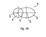
- FIG. 1B is a schematic representation of a combination hole of the bone plate of FIG. 1A .
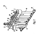
- FIG. 2 is a perspective view of the assembled components of a first embodiment of the aiming guide system of the present invention.
- FIG. 3 is a side view of the aiming guide system of FIG. 2 .
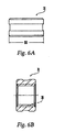
- FIG. 4A is a side view of the interlocking bolt.
- FIG. 4B is a cross-sectional view of the interlocking bolt of FIG. 4A .
- FIG. 5A is a cross-sectional view of the handle of FIG. 2 .
- FIG. 5B is a top view of the handle of FIG. 2 .
- FIG. 6A is a side view of the locking nut.
- FIG. 6B is a cross-sectional view of the locking nut of FIG. 6A .
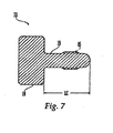
- FIG. 7 is a cross-sectional view of the coupling bolt.
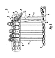
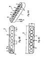
- FIG. 8A is a perspective view of the aiming arm of FIG. 2 .
- FIG. 8B is a bottom view of the aiming arm of FIG. 2 .
- FIG. 8C is a top view of the aiming arm of FIG. 2 .
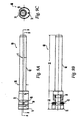
- FIG. 9A is a side view of the lock neutral guide.
- FIG. 9B is a side view, and partial cross-sectional, of the lock neutral guide of FIG. 9A , rotated 90 degrees.
- FIG. 9C is a plan view of the lock neutral guide of FIG. 9A .
- FIG. 10A is a side view of the thumb screw.
- FIG. 10B is a cross-sectional view of the thumb screw of FIG. 10A .
- FIG. 11 is a perspective view of the assembled components of a second embodiment of the aiming guide system of the present invention.
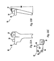
- FIG. 12A is a side view of the handle of FIG. 11 .
- FIG. 12B is a side view of the handle of FIG. 11 , rotated 90° from the view of FIG. 12A .
- FIG. 12C is a top view of the handle of FIG. 2 .
- FIG. 12D is a rear view of the assembled components of the aiming guide system of FIG. 11 .
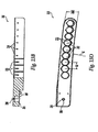
- FIG. 13A is a side view of the arm of FIG. 11 .
- FIG. 13B is a side view, and partial cross-sectional view, of the arm of FIG. 11 .
- FIG. 13C is a bottom view of the aiming arm of FIG. 11 .
- FIG. 13D is a top view of the aiming arm of FIG. 11 .
- FIG. 13E is a side cross-sectional side view of the arm of FIG. 11 .
- FIG. 13F is a cross-sectional view taken along axis 9A-9A of FIG. 13E .
- FIGS. 14A and 14B are side views of two examples of a bone anchor that may be used with the aiming guide system.
- FIG. 1A illustrates one example of a section of a bone plate 90 having one illustrative embodiment of holes 4 with which the aiming guide system is intended to be used.
- FIG. 1A illustrates a bone plate 90 which includes an upper surface 1, a bone contacting or lower surface 2 (not shown), and a plurality of combination holes 4 extending through the upper surface 1 and lower surface 2.
- the holes 4 may be elongated (e.g., in a direction substantially aligned with a longitudinal axis of the plate) and may include a threaded portion 5 and a non- threaded portion 6.
- the threaded portion 5 may extend over a range of greater than about 180° with respect to a center point C1 of a first circular portion P1 along which the threaded portion lies (discussed below).
- the threaded portion 5 of the hole 4 may be dimensioned and configured to engage a threaded head of a bone screw, and fix the bone screw at a predetermined angle with respect to the bone plate.
- the threaded portion 5 extends through the full thickness of the bone plate, i.e., from the upper surface 1 to the lower surface 2, thus maximizing the stability of the bone screw to bone plate interface.
- the same type of screw, or other types of screws, including screws not having threaded heads, may pass through the non-threaded portion 6 of a combination hole 4.
- the specifications of U.S. patent No. 6,669,701 and of United States patent No. 6,719,759 disclose combination holes.
- FIG. 1B is a schematic representation of the combination hole of FIG. 1A .
- This combination hole may have a first circular portion PI (along which the threaded portion 5 may lie) and a second elongated portion P2 (along which the non-threaded portion 6 may lie).
- the first circular portion P1 and the second elongated portion P2 overlap one another and are thus in communication with one another.
- the first circular portion P1 defines a first center point C1.
- the second elongated portion P2 defines a second center point C2. In between these two points is a central point C3.
- FIG. 2 is a perspective view of the assembled components of a first preferred embodiment of the aiming guide system 20.
- the aiming guide system 20 provides alignment between a surgical tool (e.g., a drill bit 100, a trochar 101) and holes or hole portions in a bone plate.
- a bone anchor e.g., bone screws 150 and 151 shown in FIGS. 14A and 14B , a pin, a tack
- a bone anchor e.g., bone screws 150 and 151 shown in FIGS. 14A and 14B , a pin, a tack
- aiming guide systems 20 and 220 are described in the context of certain bone plates with certain hole arrangements and hole configurations, it should be noted that the aiming device may be utilized with any bone plate with virtually any hole distribution arrangement and virtually any hole configuration.
- the aiming guide system 20 includes a handle 30.
- the handle 30, at its lower end 34, may be attached to a bone plate 90.
- the handle 30, at its upper end 35, may be attached to, or may be integral with, an aiming arm 10.
- the aiming arm 10 may extend substantially parallel to the bone plate 90 in the lengthwise direction and may have multiple bores 12. There may be any number of bores 12 in aiming arm 10.
- the arrangement/pattern of the bores 12 preferably matches the arrangement/pattern of the holes in the bone plate 90.
- FIG. 8C is a plan view of the top surface of aiming arm 10.
- the bores 12 may be staggered to match a bone plate with a corresponding arrangement of staggered holes.
- Each bore 12 is preferably aligned with the central point (C3 in FIGS. 1A and IB) of a corresponding bone plate hole.
- the aiming arm 10 is substantially straight along its longitudinal axis and the bores 12 may be substantially perpendicular to the top surface 8 of the aiming arm 10.
- the top surface 8 of the aiming arm 10 is also substantially flat and planar.
- the bores 12 may extend through the arm 10 at a non-perpendicular angle with respect to the top surface 8 of arm 10 and may be angled in one, two, or three planes.
- the top surface 8 of the arm 10 may be curved and/or twisted along its longitudinal axis, curved and/or twisted along its width, or curved in both directions.
- the aiming arm 10 also may bowed instead of flat and planar.
- a tool guide for example lock neutral guide 60, may be positioned in a bore 12 of the aiming arm and may extend to a corresponding bone plate hole 4. Thumb screws 15 may be inserted (e.g., threaded) into side holes 14 in the aiming arm 10 in order to retain the guides 60 in the bores 12.
- the guide 60 may be inserted into the bore 12 in one of at least two different preset positions in order to align the guide 60 with a particular hole portion of a bone plate hole 4. (The details of which are illustrated in FIGS. 3 , 8A-8C and 9A-9C and are discussed more fully below.)
- a tool e.g., a drill bit, a trochar
- FIG. 3 is a side view of the assembled components of the first preferred embodiment of the present invention.
- the handle 30 may, at its lower end 34, be attached to the bone plate 90 in any number of ways.
- the handle 30 is attached to the bone plate 90 by an interlocking bolt 40, which threads into a specific reference-point hole 91 in the bone plate 90.
- the interlocking bolt 40 may have a head 41, a shaft 42, and an externally-threaded end 43.
- the lower end 34 of handle 30 is wider than, and straddles, the bone plate 90.
- the handle 30 may have a longitudinal bore or chamber 37 for insertion of interlocking bolt 40.
- the chamber 37 may extend from the upper surface to the lower surface of handle 30.
- interlocking bolt 40 may be cannulated to allow for the insertion of a guide wire through the interlocking bolt 40 and into hole 91 in the bone plate 90.
- a locking nut 31 (shown in FIG. 6A ) may be positioned on the shaft 42 of the interlocking bolt 40 and positioned to abut the head 41 of the interlocking bolt 40. As shown in FIGS. 6B and 4B , the locking nut 31 may have internal threads 38 to mate with an externally threaded portion 48 on the interlocking bolt 40. After the interlocking bolt 40 has been inserted through the chamber 37 of the handle and threaded into the hole 91 of the bone plate, the locking nut 31 may be rotated to take up any slack in the connection between the handle 30 and the bone plate 90. As shown in FIG. 6A , the locking nut 31 may knurled to aid the operator in gripping the nut 31 when rotating it.
- the nut 31 preferably has a diameter DN of about 1.0cm to 1.8cm.
- the interlocking bolt 40 preferably has a length LI of about 13cm to 14cm and a primary diameter DI of about 0.7cm to about 0.9cm.
- the chamber 37 may have a diameter suitable to accommodate the interlocking bolt 40.
- Handle 30, at its upper end 35, may be integral with, or attachable to, the aiming arm 10.
- the aiming arm 10 may be aligned with the handle 30 in any number of ways as those skilled in the art will appreciate.
- pins 32 serve to align the handle 30 with the aiming arm 10.
- the pins may be integral with the handle 30 and mate with corresponding holes 17 in the arm 10, or vice versa, hi another embodiment, unattached pins 32 may mate with corresponding holes 36 and 17 in both the handle 30 and arm 10, respectively.
- Pin holes 36 in the top surface of handle 30 are shown in FIG. 5B .
- Pin holes 17 in the bottom surface of aiming arm 10 are shown in FIG. 8B .
- the handle 30 is removably attachable to the aiming arm 10.
- the handle 30 may be secured to the aiming arm 10 in any number of ways.
- One end of the aiming arm may be positioned over the top surface of the handle.
- the handle 30 is secured to the aiming arm 10 by a coupling bolt 33.
- coupling bolt 33 may have a head 18 and a shaft 19. The shaft 19 may pass through a corresponding hole 16 (shown in FIG.
- Shaft 19 may have external threads 85 (shown in FIG. 7 ) to mate with corresponding internal threads 86 (identified in FIG. 8B ) of the hole 16 of aiming arm 10 and to mate with corresponding internal threads 46 (shown in FIG. 4B ) on the inner surface of hole 44 of the interlocking bolt 40.
- Shaft 19 preferably has a length LC of about 1.1cm to 1.7cm and a diameter DC of about 0.4cm to 0.6cm.
- Handle 30 preferably has a height HH of about 10cm to 14cm.
- FIGS. 8A (a perspective view of the aiming arm 10) and 8C (a top view of the aiming arm 10) illustrate bores 12, each having two diametrically opposed slots 13 formed in their inner surfaces 49. Slots 13 preferably do not extend from the top surface 8 to the bottom surface 7 of the aiming arm 10.
- FIG. 8B which is a bottom view of the arm 10.
- the arm 10 preferably has a length LA of about 14cm to about 19cm and a width WA of about 2.5cm to about 3.5cm.
- Bore 12 preferably has a diameter DB of about 1.3cm to about 1.9cm.
- the distance b between adjacent bore 12 centers is preferably about 1.5cm to about 2.1 cm.
- the length LA, width WA, distance b between adjacent bore holes, and the orientation of the bores 12 can be varied.
- the lock neutral guide 60 may have a head 61 and a sleeve 62.
- a channel 65 may extend through the head 61 and sleeve 62.
- the channel 65 and sleeve 62 may be eccentric with respect to the head 61 and bore 12 (i.e., the channel and sleeve may not be positioned at the geometric center of the head 61 and bore 12).
- the central longitudinal axis B-B of the sleeve 62 may be offset from the central longitudinal axis A-A of the head 61.
- the distance d between axis A-A and axis B-B is preferably about 0.16cm to about 0.20cm. It will be appreciated that this eccentricity will serve to align the guide sleeve 62 with different portions of a combination hole (e.g., combination hole 4).
- the heads 61 of the lock neutral guides 60 may have a first portion 70 with diameter DI and a second portion 71 with diameter D2, the diameter D2 being greater than the diameter DI.
- the diameter D2 may also be greater than the Diameter D3 (shown in FIG. 9A ) of the bore.
- Diameter DI may be slightly smaller than D3 such that there is a slip fit between the first portion 70 of head 61 of guide 60 and the bore 12.
- the outer surface of the first portion 70 of guide 60 may contact the inner surface of the bore 12, but the "fit" between the two may be sufficiently loose to allow for manual movement of the guide 60 with respect to the bore 12.
- Diameter DI is preferably about 1.3cm to about 1.8cm.
- Diameter D2 is preferably about 1.7cm to about 2.1 cm.
- Diameter D3 is preferably about 1.3cm to about 1.9cm.
- the lock neutral guides 60 may have, at the circumferential outer surface of their heads 61, two radially-extending, diametrically-opposed knobs 63. Knobs 63 may mate with the two corresponding diametrically opposed slots 13 (shown in FIG. 8A ) formed in the inner surface of the bores 12 of aiming arm 10. Thus, when positioned in slots 13, the knobs 63 prevent a lock neutral guide 60 from rotational movement relative to the bore 12 and arm 10. Lock neutral guide 60, in the embodiment of FIGS. 2 and 11 , may be positioned within the bore 12 in either of two possible predetermined positions.
- the eccentric channel 65 and sleeve 62 In one position, the eccentric channel 65 and sleeve 62 is offset in one direction and is therefore aligned with one side of the combination hole. In the other position, 180 degrees rotated from the first position, the eccentric channel 65 (and sleeve 62) is offset in the opposite direction and is therefore aligned with the other side of the combination hole.
- the knobs 63 of the tool guide and the slots 13 of the bores 12 may be dimensioned and configured such that the eccentricity of the sleeve 62 and channel 65 is offset from the center (of the bore 3 and head 61) in a direction and distance corresponding to the dimensions of the given plate hole. The surgeon thus has the option to align the sleeve 62, and hence the surgical tool, with either of the hole portions of a combination hole.
- Shaft 62 of guide 60 preferably has a length LS of about 11 cm to about 12cm and a diameter DS of about 0.7cm to about 1.1 cm.
- Head 61 preferably has a length LH of about 3.0cm to about 3.5cm.
- Knobs 63 extend radially beyond the outer circumference of the head 61 preferably by about 0.20cm to about 0.22cm.
- the heads 62 of the lock neutral guides 60 may be generally circular.
- the second portion 71 of the head 62 may be generally circular, but have two segments of the circumference interrupted by two flat portions 74. Second portion 71 of head 62 may therefore be wide enough to prevent over-insertion of the guide 60 into the bore 12, but narrow enough in the direction facing other bores 12 to prevent heads 62 of guides 60 placed in closely adjacent bores from obstructing each other.
- any configuration or relationship between the lock neutral guide 60 and the bore 12 may be established and used to limit the guide 60 to preset positions within a bore 12 and to prevent relative rotational movement.
- the mating arrangement could be reversed: the knobs could extend radially inward from the bore 12 and mate with slots formed on the outside of the guide 60.
- the guide 60 could have more sizeable (e.g. wider and longer) radially extending protrusions, to mate with corresponding recesses on the internal surface of the bore 12.
- head 62 and bores 12 could be keys so as to limit the position of the sleeve within the bore to one, two, or more predetermined positions so that the channel 65 will align with different areas of the bone plate hole depending upon the position of the head 62 with respect to the bore 12.
- the eccentric channel 65 and sleeve 62 may be used with aiming arms having properties, features, and a configuration that are different from the aforedescribed aiming arm 10.
- the bores 12 of the aiming arm 10 may be perfectly aligned with the center (e.g., center C1 or C2 shown in FIGS. 1A and 1B ) of one of multiple hole positions of a combination hole (rather than with the central point, e.g., center C3 shown in FIGS. 1A and 1B of a combination hole).
- the bore 12 may receive a tool guide in only one position (rather than in two positions).
- a guide with a center sleeve could be used to align a tool with the portion of a combination hole that the bore is aligned with. If a surgeon wishes to penetrate or access another portion of a hole, a guide with a suitably eccentric sleeve may be used. The degree of eccentricity, it will be appreciated, would be greater in this embodiment than in the aforementioned embodiments.
- a surgeon can access different portions of a hole, preferably an elongated or overlapping hole, by selecting the appropriate sleeve (rather than by using one sleeve and selecting the appropriate orientation).
- the one-sleeve system is preferred.
- FIG. 10A is a side view of the thumb screw 15.
- thumb screw 15 has a head 80 and a penetrating shaft 81.
- Thumb screws 15 penetrate through side holes 14 of aiming arm 10 and into grooves 79 formed in the outer surface of heads 61 of lock neutral guides 60 in order to retain guides 60 in the bores 12.
- shaft 81 has external threads 88 (shown in FIG. 10B ) which mate with internal threads (not shown) of side holes 14 of aiming arm 10.
- Shaft 81 preferably has a length LT of about 0.8cm to about 1.2cm and a diameter DT of about 0.19cm to about 0.25cm.
- FIG. 11 is a perspective view of the assembled components of an aiming guide system 220.
- the embodiment shown in FIG. 11 is intended for use with a bone plate which, for example, along its shaft, has a twist.
- the plate may be a proximal tibia plate, but could be a bone plate for other bones as well, including plates for other long bones.
- the plate 290 may have a head 294 and a shaft 298.
- the plate 290 may have holes which, due to the twist of the shaft 298, may be angled in one, two, or three planes.
- most or all of the plate holes on the shaft 298 may be oriented at progressively increasing angles (i.e., in FIG. 11 each hole may be oriented at an angle greater than the hole to its left, with the hole at the free end of the shaft 298, the end opposite the head 294, having the greatest angle as a result of the greater twist of the free end of the shaft 298).
- the aiming arm 10 may not be compatible with the plate 290 (i.e., the lock neutral guides would not be positioned at the plate holes at the proper insertion angles).
- the aiming arm 210 is specifically designed to complement a plate having a twist, a bend, or holes oriented at different angles.
- the aiming arm 210 unlike the aiming arm 10, may extend and be substantially non-parallel to the bone plate in a lengthwise direction. As shown in FIG. 13D (which is a top view of aiming arm 210), aiming arm 210 may be curved sideways.
- the radius of curvature R of arm 210 may be about 140cm to about 170cm.
- the curvature of the aiming arm 210 places the bores 212 laterally away from the plate holes. As the aiming arm 210 extends in a the general direction of the length of the bone plate 290 and away from the handle 230, most of the bores 212 are distanced progressively further away from the corresponding holes in the plate 290. The effect of locating the bores 212 away from the plate holes is to accommodate the twist in the bone plate which orients the axes of the bone plate holes at an angle relative to the top surface 208 and the bottom surface 207 of the aiming arm 210.
- the arm bores 212 may be angled in a direction and at a degree dictated by and matching the angle of the corresponding hole. Thus, as the plate holes are biased from the head end 55 of the shaft 298 to the free end 56 of the shaft 298 at progressively increasing angles, so too may the bores 212 be oriented from the handle-end 58 of the arm 210 to the free end 59 of the arm 210 at progressively increasing angles.
- the arm bores 212 may have an angled countersink region 57 to accommodate the heads of lock neutral guides 60. Without the countersink region 57, there is only minimal contact and hence minimal stability between the heads of the lock neutral guides 60 and the aiming arm 210.
- the countersink region 57 which may be formed of one or more cutouts or indentations around at least a portion of the bores 212 near the upper surface 208 of the aiming arm 210, provides for additional contact between the heads of lock neutral guides 60 and the aiming arm 210.
- each of the bores 212 may be oriented at an angle relative to the aiming arm 210 in two planes.
- a first plane defined by the cross section of the arm 210 shown in FIG. 13E
- the bores 212 may all be biased to the same degree, creating an angle ⁇ , as shown in FIG. 13E .
- the bores may be oriented in a direction toward the free end of the arm 210 by about 0.1° to about 1.5°, creating an angle ⁇ of about 90.1° to about 91.5°.
- the boxes 212 can be oriented in the plane shown in FIG. 13E by a larger or smaller angle and in a different direction. It can further be appreciated that the angle of the orientation in this first plane can change for each bore 212.
- the bores 212 may be oriented in a second plane through the aiming arm.
- the bores 212 may be oriented in a direction toward the bone plate at varying degrees denoted by angle in FIG. 13F (which is a cross-sectional view of the arm 210 taken along the axis 9A-9A of FIG. 13E ).
- the second plane in this illustrative embodiment is defined by the plane perpendicular to the first plane and in the plane defined by each pair of slots 213.
- angle ⁇ may vary from about 0° to about 5°.
- the bore 212' shown in FIGS.
- the bore 212" located nearest to the handle 230 may have no angle (i.e., angle ⁇ of 0°), and the bore 212" (noted at cross section 9A-9A and shown in FIGS. 13E and 13F ) located at the opposite and free end of arm 210 may have an angle ⁇ of about 5°.
- the bores 212 in between the two end bores 212' and 212" may each have different angles ⁇ between about 0° and about 5°, gradually increasing from about 0° to about 5° along the aiming arm 210 from the end bore 212' to 212".
- the respective angles ⁇ may be different from the aforementioned angles ⁇ , in range, in progression/assortment, and/or in direction.
- the arm 210 has nine bores 212, and the arm 210 preferably has a length LA2 of about 21 cm to about 27cm and a width WA2 of about 3.0cm to about 3.6cm.
- each bore 212 has a diameter DB2 of about 2.0cm to about 2.4cm.
- the distance b2 between adjacent bore 212 centers may be about 1.5cm to about 2.1 cm.
- an aiming arm having a twist and curve corresponding to the twist and curve of a bone plate, and having straight bores may be used to accommodate a bone plate having a twist.
- FIGS. 12A, 12B, and 12C are side and top views of a handle 230 for the aiming guide system 220.
- the handle 230 may have a longitudinal bore or chamber 237 for insertion of an interlocking bolt, which may secure the handle 230 to the bone plate 290 in similar fashion to how the interlocking bolt 40 secures the handle 30 to the plate 90, as described above.
- the interlocking bolt of this embodiment may be similar in form and function to the interlocking bolt 40.
- the interlocking bolt of this embodiment may have similar dimensions and measurements to those of the interlocking bolt 40 or may be varied as necessary.
- the handle may have a platform 239 on which the end portion 211 (shown in FIG. 13A ) of arm 210 sits, and may have an upward projection 238, which may be received in a corresponding hole 287 (shown in FIGS. 13B and 13E ) on the end portion 211 of arm 210.
- pins like pins 32
- holes 236 shown in FIG. 12C
- holes 217 shown in FIG. 13C and 13E
- a coupling bolt 33 may be used to secure the arm 210 to the handle 230.
- the coupling bolt 33 may have a shaft 19 which may pass through a hole 216 (shown in FIGS. 13B, 13D , and 13E ) in the aiming arm 210 and mate with a hole 233 on the upper surface of the projection 238 of the handle 230.
- Shaft 19 of coupling bolt 33 may have external threads 85 (shown in FIG. 7 ) to mate with corresponding internal threads 286 (identified in FIG. 13D ) of the hole 216 of aiming arm 210 and with corresponding internal threads 246 on the inner surface of hole 233 on the platform 239 of the handle 230.
- the handle 230 may extend from the plate at a non-perpendicular angle [delta] with respect to trie plane defined by the upper surface of the head 294 of the plate 290.
- the handle 230 may extend at a non-perpendicular angle, for example, in order to provide space for the use of additional instrumentation to be used to operate the system.
- handle 230 may extend from the plate 290 at an angle ⁇ from about 10° to about 20° as shown in FIG. 12D .
- the angle ⁇ may be determined by the orientation of the reference hole in which the interlocking bolt is inserted.
- the handle 230 preferably, in a non-limiting example, has a height HH2 of about 10cm to about 14cm, although other dimensions are probable.
- the lock neutral guides 60 may be used with aiming arm 210 as they are used with aiming arm 10. Bores 212 have diametrically opposed slots 213 on their inner surfaces. To secure the guides 60 in the bores 212, thumb screws 15 may penetrate side holes 214 of aiming arm 210 and may otherwise be used as described above in connection with the first preferred embodiment.
- the bores through the aiming arm can be arranged at different angles -- and in one, two, or three planes -- through the aiming arm and the aiming arm can be curved, twisted, or bent in one, two, or three planes which will all be a matter of design choice. Accordingly, it should be understood that the embodiments of the invention described above are not intended as limitations on the scope of the invention, which is defined only by the following claims.
Landscapes
- Health & Medical Sciences (AREA)
- Life Sciences & Earth Sciences (AREA)
- Orthopedic Medicine & Surgery (AREA)
- Surgery (AREA)
- Medical Informatics (AREA)
- Engineering & Computer Science (AREA)
- Biomedical Technology (AREA)
- Heart & Thoracic Surgery (AREA)
- Nuclear Medicine, Radiotherapy & Molecular Imaging (AREA)
- Molecular Biology (AREA)
- Animal Behavior & Ethology (AREA)
- General Health & Medical Sciences (AREA)
- Public Health (AREA)
- Veterinary Medicine (AREA)
- Dentistry (AREA)
- Oral & Maxillofacial Surgery (AREA)
- Surgical Instruments (AREA)
Description
- The present invention relates to an apparatus for aligning surgical tools (e.g., drill bit, trochar) with a hole in bone plate.
- Surgical devices which align tools (e.g., drill bits, trochars) to bone plate holes are known in the art. Many of these devices are not adjustable. Some of these known devices can be adjusted by the surgeon or operator to tailor it for use with a number of different bone plates which have varying hole placement arrangements or patterns. These adjustable devices, however, require the surgeon or operator to manually adjust the guide to suit the particular plate being used. Making these adjustments can be tedious and often requires trial and error. Furthermore, even after a surgeon adjusts one of these devices, the alignment between the guide and a respective plate hole may be imprecise. These problems become even more salient when the device being used is intended to align a tool (e.g., a drill bit) with so-called bone plate "combination holes." Indeed, it appears that no existing alignment device is designed for, or even particularly compatible with, a plate that has combination holes. A "combination hole," as used here, means any kind of hole in which there are multiple "hole positions" any one of which a surgeon can drill or operate through. For an example, see the combination holes disclosed in
U.S. patent No. 6,669,701 and the combination holes disclosed in United States patent No.6,719,759 . An aiming guide system according to the preamble of claim 1 of the present patent application is disclosed inEP-A-0468192 . - There thus exists a need for a device that will align a surgical tool (e.g., drill bit) with a bone plate hole or that can be "adjusted" or aligned with a bone plate hole or a portion of a bone plate hole with minimal effort and maximum precision. This need is especially evident when a bone plate having combination holes is used. The present invention addresses this problem and others by providing an aiming arm which has aligning bores, whose arrangement matches or corresponds to the arrangement of holes of a particular bone plate type. When adjustment is needed, for example when a bone plate that has combination holes is being used, the present invention may provide an aiming arm that has guide bores, each guide bore having multiple (i.e., at least 2) preset positions in which to introduce or position a guide sleeve, each position providing for alignment with a particular, different hole portion. Because the positions are preset, maneuvering each guide sleeve to the desired position is very easy and takes a very short amount of time.
- The aiming guide system of the present invention provides alignment between at least one surgical tool (e.g., a drill bit, a trochar) and holes or hole in a bone plate. The aiming guide system comprising an arm portion having a longitudinal axis, top and bottom surfaces and first and second ends, and at least one bore extending through the arm portion from the top surface to the bottom surface and a tool guide having a longitudinal axis and a channel in the direction of the longitudinal axis of the tool guide. The tool guide has a head and a sleeve portion, whereby the head is positioned at least in part within said bore, the channel being centered with respect to the sleeve portion and the sleeve portion and channel being eccentric with respect to the head. The bore of the arm portion and tool guide are configured and adapted such that the tool guide is received in the bore in at least two different preset positions which locates the channel in at least two different hole positions.
- The aiming guide system may be used with a bone plate having virtually any hole distribution arrangement and virtually any hole configuration. In a preferred embodiment, the aiming guide system is used with a plate having "combination holes." A combination hole is any kind of hole in which there are multiple "hole positions" any one of which a surgeon can penetrate or access. One example of a combination hole is an elongated hole extending from an upper surface of a bone plate to a lower surface of a bone plate, and which has a threaded portion and a non-threaded portion. The threaded portion may extend over a range of greater than half of the hole's circumference. The threaded portion of the hole may be dimensioned and configured to engage a threaded head of a bone screw, and fix the bone screw at a predetermined angle with respect to the bone plate. The same type of screw or other types of screws, including screws not having threaded heads, may pass through the non-threaded portion of a combination hole at any one of a number of angles.
- The aiming guide system may have an aiming arm. In a first preferred embodiment, the arm extends substantially parallel to the bone plate in its lengthwise direction and has multiple bores. In a second preferred embodiment, the arm curves sideways, away from the bone plate. There may be any number of bores in the aiming arm. The arrangement/pattern of the bores preferably matches or corresponds to the arrangement/pattern of the holes in the bone plate. Each bore is preferably aligned with the center of a corresponding bone plate hole (which may be in between the respective centers of each hole portion). In the second preferred embodiment in which the arm curves away from the bone plate, the bores may be oriented at a non-perpendicular angle with, respect to the plane defined by the top surface of the arm.
- In a preferred embodiment, a tool guide may be positioned to run substantially straight between a bore of the aiming arm and a corresponding bone plate hole. In a preferred embodiment, the guide has a head and a sleeve. A channel may extend through the head and sleeve. The channel may be centered with respect to the sleeve.
- The channel and sleeve may be eccentric with respect to the head of the guide and the bore of the arm (i.e., the channel and sleeve may not be positioned at the geometric center of the head and bore). This eccentricity serves, as described below, to align the guide sleeve with any one of multiple positions within a given combination hole.
- In a preferred embodiment, the tool guides have, at their heads, two radially-extending, diametrically-opposed knobs. The knobs may mate with two corresponding diametrically opposed slots formed in the inner surface of each of the bores of aiming arm. Thus, when positioned in the slots, the knobs prevent a tool guide from rotational movement relative to the bore and arm. The lock neutral guide may be placed within the bore in either of two possible positions. In one position, the eccentric channel (and sleeve) is offset from center in one direction and is therefore aligned with one side of a combination hole. In the other position, 180 degrees rotated from the first position, the eccentric channel (and sleeve) is offset from center in the opposite direction and is therefore aligned with the other side of the combination hole. To accomplish this, the knobs of the tool guide and the slots of the bores may be dimensioned and configured such that the eccentricity of the sleeve and channel is offset from the center in a direction corresponding with the direction of the array of hole positions within a given plate hole. The surgeon thus has the option to align the sleeve, and hence the surgical tool being used, with either of the hole portions of a combination hole.
- In a preferred embodiment, a handle connects the aiming arm to the bone plate. The handle, at its lower end, may be secured to the bone plate. A locking bolt may penetrate a substantially vertical chamber in the handle and may secure the handle to the bone plate by being threaded into a bone plate hole. The handle, at its upper end, may be secured to the aiming arm. In a preferred embodiment, the handle is secured to the aiming arm by a coupling bolt. The coupling bolt may have a head and a shaft. The shaft may pass through a corresponding hole in the aiming arm and mate with a hole located at the top surface of the head of the interlocking bolt or at an upper surface of the handle.
- These figures represent preferred embodiments of the aiming guide system. Those skilled in the art will recognize that numerous variations and modifications may be made without departing from the scope of the present invention. Accordingly, it should be understood that these figures are not intended as limitations on the scope of the invention, which is defined only by the claims.
-
FIG. 1A is a plan view of a segment of a bone plate having combination holes. -
FIG. 1B is a schematic representation of a combination hole of the bone plate ofFIG. 1A . -
FIG. 2 is a perspective view of the assembled components of a first embodiment of the aiming guide system of the present invention. -
FIG. 3 is a side view of the aiming guide system ofFIG. 2 . -
FIG. 4A is a side view of the interlocking bolt. -
FIG. 4B is a cross-sectional view of the interlocking bolt ofFIG. 4A . -
FIG. 5A is a cross-sectional view of the handle ofFIG. 2 . -
FIG. 5B is a top view of the handle ofFIG. 2 . -
FIG. 6A is a side view of the locking nut. -
FIG. 6B is a cross-sectional view of the locking nut ofFIG. 6A . -
FIG. 7 is a cross-sectional view of the coupling bolt. -
FIG. 8A is a perspective view of the aiming arm ofFIG. 2 . -
FIG. 8B is a bottom view of the aiming arm ofFIG. 2 . -
FIG. 8C is a top view of the aiming arm ofFIG. 2 . -
FIG. 9A is a side view of the lock neutral guide. -
FIG. 9B is a side view, and partial cross-sectional, of the lock neutral guide ofFIG. 9A , rotated 90 degrees. -
FIG. 9C is a plan view of the lock neutral guide ofFIG. 9A . -
FIG. 10A is a side view of the thumb screw. -
FIG. 10B is a cross-sectional view of the thumb screw ofFIG. 10A . -
FIG. 11 is a perspective view of the assembled components of a second embodiment of the aiming guide system of the present invention. -
FIG. 12A is a side view of the handle ofFIG. 11 . -
FIG. 12B is a side view of the handle ofFIG. 11 , rotated 90° from the view ofFIG. 12A . -
FIG. 12C is a top view of the handle ofFIG. 2 . -
FIG. 12D is a rear view of the assembled components of the aiming guide system ofFIG. 11 . -
FIG. 13A is a side view of the arm ofFIG. 11 . -
FIG. 13B is a side view, and partial cross-sectional view, of the arm ofFIG. 11 . -
FIG. 13C is a bottom view of the aiming arm ofFIG. 11 . -
FIG. 13D is a top view of the aiming arm ofFIG. 11 . -
FIG. 13E is a side cross-sectional side view of the arm ofFIG. 11 . -
FIG. 13F is a cross-sectional view taken along axis 9A-9A ofFIG. 13E . -
FIGS. 14A and 14B are side views of two examples of a bone anchor that may be used with the aiming guide system. - The aiming guide system is described below with reference to the illustrated embodiments. Those skilled in the art will recognize that numerous variations and modifications may be made without departing from the scope of the present invention. Accordingly, it should be understood that the embodiments of the invention described above are not intended as limitations on the scope of the invention, which is defined only by the claims.
-
FIG. 1A illustrates one example of a section of a bone plate 90 having one illustrative embodiment of holes 4 with which the aiming guide system is intended to be used.FIG. 1A illustrates a bone plate 90 which includes an upper surface 1, a bone contacting or lower surface 2 (not shown), and a plurality of combination holes 4 extending through the upper surface 1 andlower surface 2. The holes 4 may be elongated (e.g., in a direction substantially aligned with a longitudinal axis of the plate) and may include a threaded portion 5 and a non- threadedportion 6. The threaded portion 5 may extend over a range of greater than about 180° with respect to a center point C1 of a first circular portion P1 along which the threaded portion lies (discussed below). The threaded portion 5 of the hole 4 may be dimensioned and configured to engage a threaded head of a bone screw, and fix the bone screw at a predetermined angle with respect to the bone plate. Preferably, the threaded portion 5 extends through the full thickness of the bone plate, i.e., from the upper surface 1 to thelower surface 2, thus maximizing the stability of the bone screw to bone plate interface. The same type of screw, or other types of screws, including screws not having threaded heads, may pass through thenon-threaded portion 6 of a combination hole 4. The specifications ofU.S. patent No. 6,669,701 and of United States patent No.6,719,759 disclose combination holes. -
FIG. 1B is a schematic representation of the combination hole ofFIG. 1A . This combination hole may have a first circular portion PI (along which the threaded portion 5 may lie) and a second elongated portion P2 (along which thenon-threaded portion 6 may lie). The first circular portion P1 and the second elongated portion P2 overlap one another and are thus in communication with one another. The first circular portion P1 defines a first center point C1. The second elongated portion P2 defines a second center point C2. In between these two points is a central point C3. - Reference is now made to
FIG. 2 , which is a perspective view of the assembled components of a first preferred embodiment of the aiming guide system 20. The aiming guide system 20 provides alignment between a surgical tool (e.g., a drill bit 100, a trochar 101) and holes or hole portions in a bone plate. By use of the aiming guide system, a bone anchor (e.g., bone screws 150 and 151 shown inFIGS. 14A and 14B , a pin, a tack) can be properly aligned with the holes in the bone plate. - Though the aiming
guide systems 20 and 220 are described in the context of certain bone plates with certain hole arrangements and hole configurations, it should be noted that the aiming device may be utilized with any bone plate with virtually any hole distribution arrangement and virtually any hole configuration. - In this first preferred embodiment, the aiming guide system 20 includes a handle 30. The handle 30, at its lower end 34, may be attached to a bone plate 90. The handle 30, at its upper end 35, may be attached to, or may be integral with, an aiming arm 10. The aiming arm 10 may extend substantially parallel to the bone plate 90 in the lengthwise direction and may have
multiple bores 12. There may be any number ofbores 12 in aiming arm 10. The arrangement/pattern of thebores 12 preferably matches the arrangement/pattern of the holes in the bone plate 90.FIG. 8C is a plan view of the top surface of aiming arm 10. Thebores 12 may be staggered to match a bone plate with a corresponding arrangement of staggered holes. Each bore 12 is preferably aligned with the central point (C3 inFIGS. 1A and IB) of a corresponding bone plate hole. - The aiming arm 10 is substantially straight along its longitudinal axis and the
bores 12 may be substantially perpendicular to the top surface 8 of the aiming arm 10. The top surface 8 of the aiming arm 10 is also substantially flat and planar. As discussed more fully below in connection with the description of another embodiment, thebores 12 may extend through the arm 10 at a non-perpendicular angle with respect to the top surface 8 of arm 10 and may be angled in one, two, or three planes. In addition, as discussed more fully below, the top surface 8 of the arm 10 may be curved and/or twisted along its longitudinal axis, curved and/or twisted along its width, or curved in both directions. The aiming arm 10 also may bowed instead of flat and planar. - A tool guide, for example lock neutral guide 60, may be positioned in a
bore 12 of the aiming arm and may extend to a corresponding bone plate hole 4. Thumb screws 15 may be inserted (e.g., threaded) into side holes 14 in the aiming arm 10 in order to retain the guides 60 in thebores 12. The guide 60 may be inserted into thebore 12 in one of at least two different preset positions in order to align the guide 60 with a particular hole portion of a bone plate hole 4. (The details of which are illustrated inFIGS. 3 ,8A-8C and 9A-9C and are discussed more fully below.) A tool (e.g., a drill bit, a trochar) may be received by the guide 60 and thereby aligned with a targeted hole portion of a given hole 4. - Reference is now made to
FIG. 3 , which is a side view of the assembled components of the first preferred embodiment of the present invention. The handle 30 may, at its lower end 34, be attached to the bone plate 90 in any number of ways. In a preferred embodiment, the handle 30 is attached to the bone plate 90 by an interlocking bolt 40, which threads into a specific reference-point hole 91 in the bone plate 90. As shown inFIG. 4A , the interlocking bolt 40 may have a head 41, a shaft 42, and an externally-threaded end 43. - In a preferred embodiment, the lower end 34 of handle 30 is wider than, and straddles, the bone plate 90. As shown in
FIGS. 5A and 5B , the handle 30 may have a longitudinal bore or chamber 37 for insertion of interlocking bolt 40. As shown inFIG. 5A , the chamber 37 may extend from the upper surface to the lower surface of handle 30. After the handle 30 is positioned on the bone plate 90, the interlocking bolt 40, may be dropped or rotated through the chamber 37 and threaded into hole 91 in the bone plate 90, while the handle 30 is kept stationary. For ease of alignment between the interlocking bolt 40 and the reference hole 91 during insertion of the interlocking bolt 40, interlocking bolt 40 may be cannulated to allow for the insertion of a guide wire through the interlocking bolt 40 and into hole 91 in the bone plate 90. - Before inserting the interlocking bolt 40 through the chamber 37 of the handle 30, a locking nut 31 (shown in
FIG. 6A ) may be positioned on the shaft 42 of the interlocking bolt 40 and positioned to abut the head 41 of the interlocking bolt 40. As shown inFIGS. 6B and4B , the locking nut 31 may have internal threads 38 to mate with an externally threaded portion 48 on the interlocking bolt 40. After the interlocking bolt 40 has been inserted through the chamber 37 of the handle and threaded into the hole 91 of the bone plate, the locking nut 31 may be rotated to take up any slack in the connection between the handle 30 and the bone plate 90. As shown inFIG. 6A , the locking nut 31 may knurled to aid the operator in gripping the nut 31 when rotating it. - The nut 31 preferably has a diameter DN of about 1.0cm to 1.8cm. The interlocking bolt 40 preferably has a length LI of about 13cm to 14cm and a primary diameter DI of about 0.7cm to about 0.9cm. The chamber 37 may have a diameter suitable to accommodate the interlocking bolt 40.
- Handle 30, at its upper end 35, may be integral with, or attachable to, the aiming arm 10. The aiming arm 10 may be aligned with the handle 30 in any number of ways as those skilled in the art will appreciate. In a preferred embodiment, pins 32 serve to align the handle 30 with the aiming arm 10. In one embodiment, the pins may be integral with the handle 30 and mate with corresponding holes 17 in the arm 10, or vice versa, hi another embodiment, unattached pins 32 may mate with corresponding holes 36 and 17 in both the handle 30 and arm 10, respectively. (See
FIG. 8A .) Pin holes 36 in the top surface of handle 30 are shown inFIG. 5B . Pin holes 17 in the bottom surface of aiming arm 10 are shown inFIG. 8B . - In a preferred embodiment, the handle 30 is removably attachable to the aiming arm 10. The handle 30 may be secured to the aiming arm 10 in any number of ways. One end of the aiming arm may be positioned over the top surface of the handle. There may be a space 87 (shown in
FIG. 8B ) in the bottom surface of aiming arm 10 to provide clearance for the head 41 of the interlocking bolt 40. In a preferred embodiment, the handle 30 is secured to the aiming arm 10 by a coupling bolt 33. As shown inFIG. 7 , coupling bolt 33 may have ahead 18 and ashaft 19. Theshaft 19 may pass through a corresponding hole 16 (shown inFIG. 8B ) in the aiming arm 10 and mate with a hole 44 located at the top surface of the head 41 of the interlocking bolt 40.Shaft 19 may have external threads 85 (shown inFIG. 7 ) to mate with corresponding internal threads 86 (identified inFIG. 8B ) of the hole 16 of aiming arm 10 and to mate with corresponding internal threads 46 (shown inFIG. 4B ) on the inner surface of hole 44 of the interlocking bolt 40. -
Shaft 19 preferably has a length LC of about 1.1cm to 1.7cm and a diameter DC of about 0.4cm to 0.6cm. Handle 30 preferably has a height HH of about 10cm to 14cm. -
FIGS. 8A (a perspective view of the aiming arm 10) and 8C (a top view of the aiming arm 10) illustrate bores 12, each having two diametricallyopposed slots 13 formed in their inner surfaces 49.Slots 13 preferably do not extend from the top surface 8 to the bottom surface 7 of the aiming arm 10. Reference is made toFIG. 8B , which is a bottom view of the arm 10. In one embodiment in which the arm 10 has sevenbores 12, the arm 10 preferably has a length LA of about 14cm to about 19cm and a width WA of about 2.5cm to about 3.5cm.Bore 12 preferably has a diameter DB of about 1.3cm to about 1.9cm. The distance b betweenadjacent bore 12 centers is preferably about 1.5cm to about 2.1 cm. Depending upon the size of the bone plate and the arrangement of the bone plate holes, the length LA, width WA, distance b between adjacent bore holes, and the orientation of thebores 12 can be varied. - As shown in
FIGS 9A and 9B , the lock neutral guide 60 may have a head 61 and a sleeve 62. A channel 65 may extend through the head 61 and sleeve 62. The channel 65 and sleeve 62 may be eccentric with respect to the head 61 and bore 12 (i.e., the channel and sleeve may not be positioned at the geometric center of the head 61 and bore 12). As shown inFIG. 9A , the central longitudinal axis B-B of the sleeve 62 may be offset from the central longitudinal axis A-A of the head 61. In a preferred embodiment, the distance d between axis A-A and axis B-B is preferably about 0.16cm to about 0.20cm. It will be appreciated that this eccentricity will serve to align the guide sleeve 62 with different portions of a combination hole (e.g., combination hole 4). - The heads 61 of the lock neutral guides 60 may have a first portion 70 with diameter DI and a
second portion 71 with diameter D2, the diameter D2 being greater than the diameter DI. The diameter D2 may also be greater than the Diameter D3 (shown inFIG. 9A ) of the bore. Diameter DI may be slightly smaller than D3 such that there is a slip fit between the first portion 70 of head 61 of guide 60 and thebore 12. The outer surface of the first portion 70 of guide 60 may contact the inner surface of thebore 12, but the "fit" between the two may be sufficiently loose to allow for manual movement of the guide 60 with respect to thebore 12. And when, as in this embodiment, diameter D2 of thesecond portion 71 is greater than diameter D3 of the bore, thesecond portion 71 will not fit within thebore 12 and instead will, at the appropriate point, stop the advancement of the guide 60 through thebore 12. Diameter DI is preferably about 1.3cm to about 1.8cm. Diameter D2 is preferably about 1.7cm to about 2.1 cm. Diameter D3 is preferably about 1.3cm to about 1.9cm. - In a preferred embodiment, as shown in
FIG. 9B , the lock neutral guides 60 may have, at the circumferential outer surface of their heads 61, two radially-extending, diametrically-opposedknobs 63.Knobs 63 may mate with the two corresponding diametrically opposed slots 13 (shown inFIG. 8A ) formed in the inner surface of thebores 12 of aiming arm 10. Thus, when positioned inslots 13, theknobs 63 prevent a lock neutral guide 60 from rotational movement relative to thebore 12 and arm 10. Lock neutral guide 60, in the embodiment ofFIGS. 2 and11 , may be positioned within thebore 12 in either of two possible predetermined positions. In one position, the eccentric channel 65 and sleeve 62 is offset in one direction and is therefore aligned with one side of the combination hole. In the other position, 180 degrees rotated from the first position, the eccentric channel 65 (and sleeve 62) is offset in the opposite direction and is therefore aligned with the other side of the combination hole. To accomplish this, theknobs 63 of the tool guide and theslots 13 of thebores 12 may be dimensioned and configured such that the eccentricity of the sleeve 62 and channel 65 is offset from the center (of the bore 3 and head 61) in a direction and distance corresponding to the dimensions of the given plate hole. The surgeon thus has the option to align the sleeve 62, and hence the surgical tool, with either of the hole portions of a combination hole. - Shaft 62 of guide 60 preferably has a length LS of about 11 cm to about 12cm and a diameter DS of about 0.7cm to about 1.1 cm. Head 61 preferably has a length LH of about 3.0cm to about 3.5cm.
Knobs 63 extend radially beyond the outer circumference of the head 61 preferably by about 0.20cm to about 0.22cm. - In one embodiment, the heads 62 of the lock neutral guides 60 may be generally circular. In a preferred embodiment, as shown in
Figure 9C , thesecond portion 71 of the head 62 may be generally circular, but have two segments of the circumference interrupted by twoflat portions 74.Second portion 71 of head 62 may therefore be wide enough to prevent over-insertion of the guide 60 into thebore 12, but narrow enough in the direction facingother bores 12 to prevent heads 62 of guides 60 placed in closely adjacent bores from obstructing each other. - Any configuration or relationship between the lock neutral guide 60 and the
bore 12 may be established and used to limit the guide 60 to preset positions within abore 12 and to prevent relative rotational movement. For example, the mating arrangement could be reversed: the knobs could extend radially inward from thebore 12 and mate with slots formed on the outside of the guide 60. Also for example, instead ofknobs 63, the guide 60 could have more sizeable (e.g. wider and longer) radially extending protrusions, to mate with corresponding recesses on the internal surface of thebore 12. In addition, the circumferential shape of head 62 and bores 12 could be keys so as to limit the position of the sleeve within the bore to one, two, or more predetermined positions so that the channel 65 will align with different areas of the bone plate hole depending upon the position of the head 62 with respect to thebore 12. - It will be appreciated that the eccentric channel 65 and sleeve 62 may be used with aiming arms having properties, features, and a configuration that are different from the aforedescribed aiming arm 10. For example, the
bores 12 of the aiming arm 10 may be perfectly aligned with the center (e.g., center C1 or C2 shown inFIGS. 1A and1B ) of one of multiple hole positions of a combination hole (rather than with the central point, e.g., center C3 shown inFIGS. 1A and1B of a combination hole). Thebore 12 may receive a tool guide in only one position (rather than in two positions). Thus, it will be appreciated that a guide with a center sleeve (rather than one with an eccentric sleeve) could be used to align a tool with the portion of a combination hole that the bore is aligned with. If a surgeon wishes to penetrate or access another portion of a hole, a guide with a suitably eccentric sleeve may be used. The degree of eccentricity, it will be appreciated, would be greater in this embodiment than in the aforementioned embodiments. Thus, in one embodiment, a surgeon can access different portions of a hole, preferably an elongated or overlapping hole, by selecting the appropriate sleeve (rather than by using one sleeve and selecting the appropriate orientation). The one-sleeve system, however, is preferred. - Reference is now made to
FIGS. 10A and 10B. FIG. 10A is a side view of thethumb screw 15. In this embodiment,thumb screw 15 has a head 80 and a penetratingshaft 81. Thumb screws 15 penetrate through side holes 14 of aiming arm 10 and into grooves 79 formed in the outer surface of heads 61 of lock neutral guides 60 in order to retain guides 60 in thebores 12. In a preferred embodiment,shaft 81 has external threads 88 (shown inFIG. 10B ) which mate with internal threads (not shown) of side holes 14 of aiming arm 10.Shaft 81 preferably has a length LT of about 0.8cm to about 1.2cm and a diameter DT of about 0.19cm to about 0.25cm. - Another embodiment, having an arm and a handle with characteristics different from those of the first embodiment, is illustrated in
FIG. 11 , which is a perspective view of the assembled components of an aimingguide system 220. The embodiment shown inFIG. 11 is intended for use with a bone plate which, for example, along its shaft, has a twist. The plate may be a proximal tibia plate, but could be a bone plate for other bones as well, including plates for other long bones. Theplate 290 may have a head 294 and a shaft 298. Theplate 290 may have holes which, due to the twist of the shaft 298, may be angled in one, two, or three planes. Moving away from the head 294, most or all of the plate holes on the shaft 298 may be oriented at progressively increasing angles (i.e., inFIG. 11 each hole may be oriented at an angle greater than the hole to its left, with the hole at the free end of the shaft 298, the end opposite the head 294, having the greatest angle as a result of the greater twist of the free end of the shaft 298). - Because the holes of the
plate 290 are, unlike the holes of the plate 90, oriented at different angles, the aiming arm 10 may not be compatible with the plate 290 (i.e., the lock neutral guides would not be positioned at the plate holes at the proper insertion angles). The aimingarm 210, however, is specifically designed to complement a plate having a twist, a bend, or holes oriented at different angles. The aimingarm 210, unlike the aiming arm 10, may extend and be substantially non-parallel to the bone plate in a lengthwise direction. As shown inFIG. 13D (which is a top view of aiming arm 210), aimingarm 210 may be curved sideways. In one non-limiting illustrative embodiment, the radius of curvature R ofarm 210 may be about 140cm to about 170cm. The curvature of the aimingarm 210 places thebores 212 laterally away from the plate holes. As the aimingarm 210 extends in a the general direction of the length of thebone plate 290 and away from thehandle 230, most of thebores 212 are distanced progressively further away from the corresponding holes in theplate 290. The effect of locating thebores 212 away from the plate holes is to accommodate the twist in the bone plate which orients the axes of the bone plate holes at an angle relative to the top surface 208 and thebottom surface 207 of the aimingarm 210. - The arm bores 212 may be angled in a direction and at a degree dictated by and matching the angle of the corresponding hole. Thus, as the plate holes are biased from the
head end 55 of the shaft 298 to the free end 56 of the shaft 298 at progressively increasing angles, so too may thebores 212 be oriented from the handle-end 58 of thearm 210 to the free end 59 of thearm 210 at progressively increasing angles. The arm bores 212 may have an angled countersink region 57 to accommodate the heads of lock neutral guides 60. Without the countersink region 57, there is only minimal contact and hence minimal stability between the heads of the lock neutral guides 60 and the aimingarm 210. Thus, the countersink region 57, which may be formed of one or more cutouts or indentations around at least a portion of thebores 212 near the upper surface 208 of the aimingarm 210, provides for additional contact between the heads of lock neutral guides 60 and the aimingarm 210. - In one embodiment, each of the
bores 212 may be oriented at an angle relative to the aimingarm 210 in two planes. In a first plane (defined by the cross section of thearm 210 shown inFIG. 13E ), thebores 212 may all be biased to the same degree, creating an angle α, as shown inFIG. 13E . In one embodiment the bores may be oriented in a direction toward the free end of thearm 210 by about 0.1° to about 1.5°, creating an angle α of about 90.1° to about 91.5°. It should be appreciated that theboxes 212 can be oriented in the plane shown inFIG. 13E by a larger or smaller angle and in a different direction. It can further be appreciated that the angle of the orientation in this first plane can change for eachbore 212. Thebores 212 may be oriented in a second plane through the aiming arm. Thebores 212 may be oriented in a direction toward the bone plate at varying degrees denoted by angle inFIG. 13F (which is a cross-sectional view of thearm 210 taken along the axis 9A-9A ofFIG. 13E ). The second plane in this illustrative embodiment is defined by the plane perpendicular to the first plane and in the plane defined by each pair ofslots 213. In one embodiment, angle γ may vary from about 0° to about 5°. In one embodiment, the bore 212' (shown inFIGS. 13E and 13F ) located nearest to thehandle 230 may have no angle (i.e., angle γ of 0°), and thebore 212" (noted at cross section 9A-9A and shown inFIGS. 13E and 13F ) located at the opposite and free end ofarm 210 may have an angle γ of about 5°. Thebores 212 in between the two end bores 212' and 212" may each have different angles γ between about 0° and about 5°, gradually increasing from about 0° to about 5° along the aimingarm 210 from the end bore 212' to 212". In other embodiments, the respective angles γ may be different from the aforementioned angles γ, in range, in progression/assortment, and/or in direction. - In an illustrative embodiment shown in
FIGS. 13A-13F , thearm 210 has ninebores 212, and thearm 210 preferably has a length LA2 of about 21 cm to about 27cm and a width WA2 of about 3.0cm to about 3.6cm. In one embodiment, each bore 212 has a diameter DB2 of about 2.0cm to about 2.4cm. In one embodiment, the distance b2 betweenadjacent bore 212 centers may be about 1.5cm to about 2.1 cm. - In an alternative embodiment, an aiming arm having a twist and curve corresponding to the twist and curve of a bone plate, and having straight bores, may be used to accommodate a bone plate having a twist.
- Reference is now made to
FIGS. 12A, 12B, and 12C , which are side and top views of ahandle 230 for the aimingguide system 220. As shown inFIG. 12A , thehandle 230 may have a longitudinal bore orchamber 237 for insertion of an interlocking bolt, which may secure thehandle 230 to thebone plate 290 in similar fashion to how the interlocking bolt 40 secures the handle 30 to the plate 90, as described above. The interlocking bolt of this embodiment may be similar in form and function to the interlocking bolt 40. The interlocking bolt of this embodiment may have similar dimensions and measurements to those of the interlocking bolt 40 or may be varied as necessary. - The connection between the
arm 210 and thehandle 230 will now be described. As shown inFIG. 12A , the handle may have aplatform 239 on which the end portion 211 (shown inFIG. 13A ) ofarm 210 sits, and may have anupward projection 238, which may be received in a corresponding hole 287 (shown inFIGS. 13B and13E ) on theend portion 211 ofarm 210. Further aligning thehandle 230 andarm portion 210, are pins (like pins 32) which may be received by holes 236 (shown inFIG. 12C ) in thehandle 230 and by holes 217 (shown inFIG. 13C and13E ) of the aimingarm 210. To secure thearm 210 to thehandle 230, a coupling bolt 33 may be used. The coupling bolt 33 may have ashaft 19 which may pass through a hole 216 (shown inFIGS. 13B, 13D , and13E ) in the aimingarm 210 and mate with ahole 233 on the upper surface of theprojection 238 of thehandle 230.Shaft 19 of coupling bolt 33 may have external threads 85 (shown inFIG. 7 ) to mate with corresponding internal threads 286 (identified inFIG. 13D ) of thehole 216 of aimingarm 210 and with correspondinginternal threads 246 on the inner surface ofhole 233 on theplatform 239 of thehandle 230. - In an optional embodiment, the
handle 230, unlike the handle 30, may extend from the plate at a non-perpendicular angle [delta] with respect to trie plane defined by the upper surface of the head 294 of theplate 290. Thehandle 230 may extend at a non-perpendicular angle, for example, in order to provide space for the use of additional instrumentation to be used to operate the system. As a non-limiting example, handle 230 may extend from theplate 290 at an angle δ from about 10° to about 20° as shown inFIG. 12D . The angle δ may be determined by the orientation of the reference hole in which the interlocking bolt is inserted. Thehandle 230 preferably, in a non-limiting example, has a height HH2 of about 10cm to about 14cm, although other dimensions are probable. - The lock neutral guides 60 may be used with aiming
arm 210 as they are used with aiming arm 10.Bores 212 have diametrically opposedslots 213 on their inner surfaces. To secure the guides 60 in thebores 212, thumb screws 15 may penetrateside holes 214 of aimingarm 210 and may otherwise be used as described above in connection with the first preferred embodiment. - While the present invention has been described with reference to the preferred embodiments, those skilled in the art will recognize that numerous variations and modifications may be made without departing from the scope of the present invention. As a non-limiting illustrative example, in order to obtain the proper alignment between the guide sleeves and the desired bone plate, the bores through the aiming arm can be arranged at different angles -- and in one, two, or three planes -- through the aiming arm and the aiming arm can be curved, twisted, or bent in one, two, or three planes which will all be a matter of design choice. Accordingly, it should be understood that the embodiments of the invention described above are not intended as limitations on the scope of the invention, which is defined only by the following claims.
Claims (21)
- An aiming guide system (20, 220) for aligning at least one surgical tool with a hole (4) in a bone plate (90, 290) comprising:an arm portion (10, 210) having a longitudinal axis, top (8, 208) and bottom surfaces (7, 207), and first and second ends, and at least one bore (12, 212) extending through the arm portion (10, 210) from the top surface (8, 208) to the bottom surface (7, 207); anda tool guide (60) having a longitudinal axis (A-A) and a channel (65) in thedirection of the longitudinal axis (A-A) of the tool guide (60) the tool guide (60) having a head (61) and a sleeve portion (62), characterized in that
the head (61) being positioned at least in part within said bore (12, 212), the channel (65) being centered with respect to the sleeve portion (62), and the sleeve portion (62) and channel (65) being eccentric with respect to the head (61),wherein the bore (12, 212) and tool guide (60) are configured and adapted such that the tool guide (60) is received in the bore (12, 212) in at least two different preset positions which locates the channel (65) in at least two different hole positions. - The aiming guide system of claim 1, wherein the at least one bore (12, 212) is offset from the longitudinal axis of the arm portion (10, 210).
- The aiming guide system of claim 1 or 2, wherein the at least one bore (12, 212) includes two diametrically opposed slots (13, 213) extending along at least a portion of a length of the bore (12, 212), the slots (13, 213) configured and dimensioned to mate with diametrically opposed knobs (63) extending radially outward from a tool guide (60).
- The aiming guide system of claim 3, wherein the tool guide (60) is inserted at a first preset position or at a second preset position rotated 180° from the first preset position, or
wherein the aiming guide system (20, 220) further comprises a bone plate (90, 290) having a hole (4), and wherein, in a first preset position, the eccentric sleeve portion (62) of the tool guide (60) and the channel (65) are aligned with a first portion of the hole (4) in the bone plate (90, 290) and, in a second preset position, the eccentric sleeve portion (62) and channel (65) are aligned with a second portion of the hole (4) in the bone plate (90, 290). - The aiming guide system of any one of claims 1 to 4, further comprising a bone plate (90, 290) having a hole (4),
wherein the bore (12, 212) is aligned with a central point (C3) of the bone plate hole (4), or
wherein the bore (12, 212) is aligned with the center of one portion (C1, C2) of the bone plate hole (4), or
wherein the arrangement of bores (12, 212) along the arm portion (10) substantially matches the arrangement of holes (4) along at least a portion of the bone plate (90, 290), or
wherein the at least one bore (12, 212) is oriented perpendicular to the top surface (8, 208) of the arm portion (10, 210). - The aiming guide system of any one of claims 1 to 5, wherein the at least one bore (12, 212) is oriented at a non-perpendicular angle with respect to the top surface (8, 208) of the arm portion (10, 210).
- The aiming guide system of claim 6, wherein the at least one bore (212) is angled in one, two, or three planes with respect to the top surface (208) of the arm portion (210), wherein preferably the angle (γ) formed in each plane is approximately 0° to approximately 5°.
- The aiming guide system of claim 1, wherein the aiming guide (20, 220) further comprises a handle portion (30, 230), the handle portion (30, 230) is adapted to connect the arm (10, 210) with a bone plate (90, 290),
wherein preferably the handle portion (30, 230) is adapted to be attached to a bone plate (90, 290). - The aiming guide system of claim 8, wherein the handle portion (30, 230) is aligned with the arm portion (10, 210) by the mating of pins both with holes (12, 212) at the bottom surface (7, 207) of arm portion (10, 210) and with corresponding holes (36, 236) at the top surface of the handle portion (30), or wherein the handle portion (30, 230) is secured to the arm portion (10, 210) by a coupling bolt (33).
- The aiming guide system of claim 9, further comprising a bone plate (90, 290) having a further hole (4), wherein the handle portion (30, 230) has a chamber (37, 237) through its length, and further comprising an interlocking bolt (40) which extends through the chamber (37, 237) and into the further hole (4) in the bone plate (90, 290),
wherein preferably the chamber (37, 237) extends the length of the handle portion (30, 230). - The aiming guide system of claim 10, wherein the interlocking bolt (40) has a head (41), a shaft (42) and an end portion, the end portion having
threads (43) for engaging said further hole (4) in a bone plate (90, 290),
wherein preferably the connection between the interlocking bolt (40) and a bone plate (90, 290) is tightened with a locking nut (31) positioned between the head (41) of the interlocking bolt (40) and the top surface of the handle portion (30, 230). - The aiming guide system of any one of claims 8 to 11, further comprising a bone plate (90, 290), wherein the handle portion (230) extends from the
bone plate (290) at a non-perpendicular angle with respect to a plane defined by a top surface of a contact region of the bone plate (290), if the surface is flat or, if the top surface is not flat, a plane that is tangential to a peak of the top surface of the contact region of the bone plate (290),
wherein preferably the angle is between approximately 10° and approximately 20°. - The aiming guide system of any one of claims 1 to 12, wherein a thumb screw (15) may be threaded into a corresponding recess in a side surface of the arm portion (10, 210) to retain the tool guide (60) in the bore (12, 212).
- The aiming guide system of any one of claims 1 to 13, wherein the central longitudinal axis (B-B) of the sleeve portion (62) of the tool guide (60) is offset from the central longitudinal axis (A-A) of the head (61) of the tool guide (60) a by distance of approximately 0.16 cm to 0.20 cm.
- The aiming guide system of any one of claims 1 to 14, wherein the arm portion (210) is curved along at least a portion of its side surfaces, wherein the radius of curvature preferably of the curved portion of the arm portion (210) is between approximately 140 cm and approximately 170 cm.
- The aiming guide system of claim 15, wherein the arm portion (210) is curved in two or three planes.
- The aiming guide system of claim 7, or of claim 7 and any one of claims 8 to 16, wherein the at least one angled bore (212) is countersunk.
- The aiming guide system of claim 7, or of claim 7 and any one of claims 8 to 17, wherein there are a plurality of angled bores (212),
- The aiming guide system of claim 18, wherein the aiming guide system (220) further comprises a bone plate (290) and each angled bore (212) is angled in a first plane with respect to a plane defined by an upper surface of the bone plate (290) and in a second different plane with respect to a plane defined by an upper surface of the bone plate (290).
- The aiming guide system of claim 19, wherein all angled bores (212) are angled, in the first plane, to the same degree,
wherein preferably the angle is between approximately 0.1° and approximately 1.5°. - The aiming guide system of claim 19 or 20, wherein each of the angled bores (212) is angled, in the second plane, to a degree different from that of any other hole,
wherein preferably the angles range from approximately 0.01° to approximately 5°.
Applications Claiming Priority (2)
| Application Number | Priority Date | Filing Date | Title |
|---|---|---|---|
| US10/981,191 US8043297B2 (en) | 2004-11-03 | 2004-11-03 | Aiming arm for bone plates |
| EP05817496A EP1809186B1 (en) | 2004-11-03 | 2005-11-03 | Aiming arm for bone plates |
Related Parent Applications (2)
| Application Number | Title | Priority Date | Filing Date |
|---|---|---|---|
| EP05817496.2 Division | 2005-11-03 | ||
| EP05817496A Division EP1809186B1 (en) | 2004-11-03 | 2005-11-03 | Aiming arm for bone plates |
Publications (2)
| Publication Number | Publication Date |
|---|---|
| EP2277461A1 EP2277461A1 (en) | 2011-01-26 |
| EP2277461B1 true EP2277461B1 (en) | 2012-08-22 |
Family
ID=35781397
Family Applications (3)
| Application Number | Title | Priority Date | Filing Date |
|---|---|---|---|
| EP10189845A Active EP2277461B1 (en) | 2004-11-03 | 2005-11-03 | Aiming guide for bone plates |
| EP10189848A Active EP2277462B1 (en) | 2004-11-03 | 2005-11-03 | Aiming guide for bone plates |
| EP05817496A Active EP1809186B1 (en) | 2004-11-03 | 2005-11-03 | Aiming arm for bone plates |
Family Applications After (2)
| Application Number | Title | Priority Date | Filing Date |
|---|---|---|---|
| EP10189848A Active EP2277462B1 (en) | 2004-11-03 | 2005-11-03 | Aiming guide for bone plates |
| EP05817496A Active EP1809186B1 (en) | 2004-11-03 | 2005-11-03 | Aiming arm for bone plates |
Country Status (10)
| Country | Link |
|---|---|
| US (2) | US8043297B2 (en) |
| EP (3) | EP2277461B1 (en) |
| JP (1) | JP5121457B2 (en) |
| KR (1) | KR101220309B1 (en) |
| CN (2) | CN101653368B (en) |
| AU (1) | AU2005301963A1 (en) |
| BR (1) | BRPI0517981B8 (en) |
| CA (1) | CA2587167C (en) |
| WO (1) | WO2006050507A1 (en) |
| ZA (1) | ZA200704518B (en) |
Families Citing this family (198)
| Publication number | Priority date | Publication date | Assignee | Title |
|---|---|---|---|---|
| US20060129151A1 (en) * | 2002-08-28 | 2006-06-15 | Allen C W | Systems and methods for securing fractures using plates and cable clamps |
| US8043297B2 (en) * | 2004-11-03 | 2011-10-25 | Synthes Usa, Llc | Aiming arm for bone plates |
| US7648508B2 (en) * | 2004-11-30 | 2010-01-19 | Stryker Trauma S.A. | Bone plating implants, instruments and methods |
| US8591516B2 (en) * | 2006-02-27 | 2013-11-26 | Biomet Manufacturing, Llc | Patient-specific orthopedic instruments |
| US9907659B2 (en) | 2007-04-17 | 2018-03-06 | Biomet Manufacturing, Llc | Method and apparatus for manufacturing an implant |
| US9339278B2 (en) | 2006-02-27 | 2016-05-17 | Biomet Manufacturing, Llc | Patient-specific acetabular guides and associated instruments |
| US9918740B2 (en) | 2006-02-27 | 2018-03-20 | Biomet Manufacturing, Llc | Backup surgical instrument system and method |
| US9173661B2 (en) | 2006-02-27 | 2015-11-03 | Biomet Manufacturing, Llc | Patient specific alignment guide with cutting surface and laser indicator |
| US8608749B2 (en) | 2006-02-27 | 2013-12-17 | Biomet Manufacturing, Llc | Patient-specific acetabular guides and associated instruments |
| US8133234B2 (en) | 2006-02-27 | 2012-03-13 | Biomet Manufacturing Corp. | Patient specific acetabular guide and method |
| US7967868B2 (en) | 2007-04-17 | 2011-06-28 | Biomet Manufacturing Corp. | Patient-modified implant and associated method |
| US8377066B2 (en) | 2006-02-27 | 2013-02-19 | Biomet Manufacturing Corp. | Patient-specific elbow guides and associated methods |
| US9345548B2 (en) | 2006-02-27 | 2016-05-24 | Biomet Manufacturing, Llc | Patient-specific pre-operative planning |
| US20150335438A1 (en) | 2006-02-27 | 2015-11-26 | Biomet Manufacturing, Llc. | Patient-specific augments |
| US8298237B2 (en) * | 2006-06-09 | 2012-10-30 | Biomet Manufacturing Corp. | Patient-specific alignment guide for multiple incisions |
| US9289253B2 (en) | 2006-02-27 | 2016-03-22 | Biomet Manufacturing, Llc | Patient-specific shoulder guide |
| US8603180B2 (en) | 2006-02-27 | 2013-12-10 | Biomet Manufacturing, Llc | Patient-specific acetabular alignment guides |
| US8407067B2 (en) | 2007-04-17 | 2013-03-26 | Biomet Manufacturing Corp. | Method and apparatus for manufacturing an implant |
| US10278711B2 (en) | 2006-02-27 | 2019-05-07 | Biomet Manufacturing, Llc | Patient-specific femoral guide |
| US8568487B2 (en) | 2006-02-27 | 2013-10-29 | Biomet Manufacturing, Llc | Patient-specific hip joint devices |
| US8473305B2 (en) | 2007-04-17 | 2013-06-25 | Biomet Manufacturing Corp. | Method and apparatus for manufacturing an implant |
| US8864769B2 (en) | 2006-02-27 | 2014-10-21 | Biomet Manufacturing, Llc | Alignment guides with patient-specific anchoring elements |
| US8241293B2 (en) | 2006-02-27 | 2012-08-14 | Biomet Manufacturing Corp. | Patient specific high tibia osteotomy |
| US9113971B2 (en) | 2006-02-27 | 2015-08-25 | Biomet Manufacturing, Llc | Femoral acetabular impingement guide |
| US8282646B2 (en) | 2006-02-27 | 2012-10-09 | Biomet Manufacturing Corp. | Patient specific knee alignment guide and associated method |
| US8858561B2 (en) | 2006-06-09 | 2014-10-14 | Blomet Manufacturing, LLC | Patient-specific alignment guide |
| US8092465B2 (en) | 2006-06-09 | 2012-01-10 | Biomet Manufacturing Corp. | Patient specific knee alignment guide and associated method |
| US8608748B2 (en) | 2006-02-27 | 2013-12-17 | Biomet Manufacturing, Llc | Patient specific guides |
| US8535387B2 (en) * | 2006-02-27 | 2013-09-17 | Biomet Manufacturing, Llc | Patient-specific tools and implants |
| US9795399B2 (en) | 2006-06-09 | 2017-10-24 | Biomet Manufacturing, Llc | Patient-specific knee alignment guide and associated method |
| EP1878393A1 (en) * | 2006-07-10 | 2008-01-16 | Stryker Trauma GmbH | Drill assembly for bone reconstruction plate |
| US20080132900A1 (en) * | 2006-11-13 | 2008-06-05 | Stryker Trauma Gmbh | Drill alignment assembly for a bone plate using tissue protection sleeves that are fixed in the bone plate |
| US9028520B2 (en) | 2006-12-22 | 2015-05-12 | The Spectranetics Corporation | Tissue separating systems and methods |
| US8961551B2 (en) | 2006-12-22 | 2015-02-24 | The Spectranetics Corporation | Retractable separating systems and methods |
| US9351744B2 (en) | 2007-05-14 | 2016-05-31 | Queen's University At Kingston | Patient-specific surgical guidance tool and method of use |
| EP2157926B1 (en) * | 2007-05-14 | 2015-04-22 | Queen's University At Kingston | Patient-specific surgical guidance tool |
| US10758283B2 (en) | 2016-08-11 | 2020-09-01 | Mighty Oak Medical, Inc. | Fixation devices having fenestrations and methods for using the same |
| US8900237B2 (en) * | 2007-08-31 | 2014-12-02 | DePuy Synthes Products, LLC | Minimally invasive guide system |
| US20090088804A1 (en) * | 2007-09-27 | 2009-04-02 | Depuy Products, Inc. | Plate holder assembly having movable guide component |
| US8808300B2 (en) * | 2007-09-27 | 2014-08-19 | Biomet C.V. | Guide assembly for use in a medical procedure |
| US8162950B2 (en) * | 2007-12-17 | 2012-04-24 | Stryker Leibinger Gmbh & Co. Kg | Bone plate instrument and method |
| SE532211C2 (en) * | 2008-03-27 | 2009-11-17 | Swemac Innovation Ab | Device for fixing bone fragments in case of bone fracture |
| EP2158863B1 (en) * | 2008-09-02 | 2013-12-11 | Stryker Trauma AG | Bone plate with synchronized thread |
| DE102009028503B4 (en) | 2009-08-13 | 2013-11-14 | Biomet Manufacturing Corp. | Resection template for the resection of bones, method for producing such a resection template and operation set for performing knee joint surgery |
| GB2473874A (en) * | 2009-09-29 | 2011-03-30 | Peter Giannoudis | Surgical plate and nail implant |
| JP2013510692A (en) | 2009-11-17 | 2013-03-28 | クィーンズ ユニバーシティー アット キングストン | Patient-specific guide for acetabular cup placement |
| US8328809B2 (en) * | 2010-01-07 | 2012-12-11 | Zimmer, Inc. | Bone plate fixation system |
| US8632547B2 (en) | 2010-02-26 | 2014-01-21 | Biomet Sports Medicine, Llc | Patient-specific osteotomy devices and methods |
| CN102791211B (en) * | 2010-03-04 | 2015-08-12 | 新特斯有限责任公司 | Ulna osteotomy system |
| US8439932B2 (en) * | 2010-05-03 | 2013-05-14 | Biomet Manufacturing Corp. | Submuscular plating system |
| US8603148B2 (en) | 2010-05-07 | 2013-12-10 | Raymond B. Raven, III | System for treating bone fractures |
| EP2389884B1 (en) | 2010-05-25 | 2013-07-31 | Stryker Trauma SA | Implant for bone fixation |
| WO2017066518A1 (en) | 2010-06-29 | 2017-04-20 | Mighty Oak Medical, Inc. | Patient-matched apparatus and methods for performing surgical procedures |
| US11806197B2 (en) | 2010-06-29 | 2023-11-07 | Mighty Oak Medical, Inc. | Patient-matched apparatus for use in spine related surgical procedures and methods for using the same |
| US11376073B2 (en) | 2010-06-29 | 2022-07-05 | Mighty Oak Medical Inc. | Patient-matched apparatus and methods for performing surgical procedures |
| US9642633B2 (en) | 2010-06-29 | 2017-05-09 | Mighty Oak Medical, Inc. | Patient-matched apparatus and methods for performing surgical procedures |
| US11039889B2 (en) | 2010-06-29 | 2021-06-22 | Mighty Oak Medical, Inc. | Patient-matched apparatus and methods for performing surgical procedures |
| GB2487331B (en) | 2010-09-27 | 2012-10-24 | Acumed Llc | Instruments having a radiopaque region to facilitate positioning a bone plate on bone |
| US9271744B2 (en) | 2010-09-29 | 2016-03-01 | Biomet Manufacturing, Llc | Patient-specific guide for partial acetabular socket replacement |
| WO2012058353A1 (en) * | 2010-10-29 | 2012-05-03 | The Cleveland Clinic Foundation | System and method for assisting with arrangement of a stock instrument with respect to a patient tissue |
| US9968376B2 (en) | 2010-11-29 | 2018-05-15 | Biomet Manufacturing, Llc | Patient-specific orthopedic instruments |
| US9241745B2 (en) | 2011-03-07 | 2016-01-26 | Biomet Manufacturing, Llc | Patient-specific femoral version guide |
| US8715289B2 (en) | 2011-04-15 | 2014-05-06 | Biomet Manufacturing, Llc | Patient-specific numerically controlled instrument |
| US9675400B2 (en) | 2011-04-19 | 2017-06-13 | Biomet Manufacturing, Llc | Patient-specific fracture fixation instrumentation and method |
| US9622759B2 (en) * | 2011-04-21 | 2017-04-18 | DePuy Synthes Products, Inc. | Spline oriented indexing guide |
| US8956364B2 (en) | 2011-04-29 | 2015-02-17 | Biomet Manufacturing, Llc | Patient-specific partial knee guides and other instruments |
| US8668700B2 (en) | 2011-04-29 | 2014-03-11 | Biomet Manufacturing, Llc | Patient-specific convertible guides |
| WO2012158253A1 (en) * | 2011-05-18 | 2012-11-22 | Synthes Usa, Llc | Aiming on plate |
| US8532807B2 (en) | 2011-06-06 | 2013-09-10 | Biomet Manufacturing, Llc | Pre-operative planning and manufacturing method for orthopedic procedure |
| US9084618B2 (en) | 2011-06-13 | 2015-07-21 | Biomet Manufacturing, Llc | Drill guides for confirming alignment of patient-specific alignment guides |
| USD738498S1 (en) | 2013-12-16 | 2015-09-08 | George Frey | Sacroiliac surgical guide |
| USD745672S1 (en) | 2012-09-18 | 2015-12-15 | George Frey | Thoracic surgical guide |
| USD775335S1 (en) | 2011-06-29 | 2016-12-27 | Mighty Oak Medical, Inc. | Multi-level surgical guide |
| US8764760B2 (en) | 2011-07-01 | 2014-07-01 | Biomet Manufacturing, Llc | Patient-specific bone-cutting guidance instruments and methods |
| US20130001121A1 (en) | 2011-07-01 | 2013-01-03 | Biomet Manufacturing Corp. | Backup kit for a patient-specific arthroplasty kit assembly |
| US8597365B2 (en) | 2011-08-04 | 2013-12-03 | Biomet Manufacturing, Llc | Patient-specific pelvic implants for acetabular reconstruction |
| US9295497B2 (en) | 2011-08-31 | 2016-03-29 | Biomet Manufacturing, Llc | Patient-specific sacroiliac and pedicle guides |
| US9066734B2 (en) | 2011-08-31 | 2015-06-30 | Biomet Manufacturing, Llc | Patient-specific sacroiliac guides and associated methods |
| US9386993B2 (en) | 2011-09-29 | 2016-07-12 | Biomet Manufacturing, Llc | Patient-specific femoroacetabular impingement instruments and methods |
| US9301812B2 (en) | 2011-10-27 | 2016-04-05 | Biomet Manufacturing, Llc | Methods for patient-specific shoulder arthroplasty |
| US9554910B2 (en) | 2011-10-27 | 2017-01-31 | Biomet Manufacturing, Llc | Patient-specific glenoid guide and implants |
| EP2770918B1 (en) | 2011-10-27 | 2017-07-19 | Biomet Manufacturing, LLC | Patient-specific glenoid guides |
| KR20130046336A (en) | 2011-10-27 | 2013-05-07 | 삼성전자주식회사 | Multi-view device of display apparatus and contol method thereof, and display system |
| US9451973B2 (en) | 2011-10-27 | 2016-09-27 | Biomet Manufacturing, Llc | Patient specific glenoid guide |
| US9662156B2 (en) * | 2011-11-18 | 2017-05-30 | DePuy Synthes Products, Inc. | Femoral neck fracture implant |
| US9237950B2 (en) | 2012-02-02 | 2016-01-19 | Biomet Manufacturing, Llc | Implant with patient-specific porous structure |
| US9050151B2 (en) | 2012-03-06 | 2015-06-09 | Stryker Trauma Sa | Bone plate and aiming block |
| WO2013165558A1 (en) | 2012-05-03 | 2013-11-07 | DePuy Synthes Products, LLC | Surgical guides from scanned implant data |
| US9949744B2 (en) * | 2012-08-30 | 2018-04-24 | Wright Medical Technology, Inc. | Implant suitable for calcaneal osteotomy |
| US9411939B2 (en) | 2012-09-12 | 2016-08-09 | DePuy Synthes Products, Inc. | Method for producing patient-specific plate |
| US9724122B2 (en) | 2012-09-14 | 2017-08-08 | The Spectranetics Corporation | Expandable lead jacket |
| KR102193250B1 (en) * | 2012-09-14 | 2020-12-23 | 신세스 게엠바하 | Multihole drill sleeve with protection sleeve |
| TW201412283A (en) * | 2012-09-17 | 2014-04-01 | Metal Ind Res & Dev Ct | Guiding device for bone fixation surgery |
| USD745673S1 (en) | 2012-09-18 | 2015-12-15 | George Frey | Lumbar surgical guide |
| USD745671S1 (en) | 2012-09-18 | 2015-12-15 | George Frey | Transitional surgical guide |
| US9204977B2 (en) | 2012-12-11 | 2015-12-08 | Biomet Manufacturing, Llc | Patient-specific acetabular guide for anterior approach |
| US9060788B2 (en) | 2012-12-11 | 2015-06-23 | Biomet Manufacturing, Llc | Patient-specific acetabular guide for anterior approach |
| US9839438B2 (en) | 2013-03-11 | 2017-12-12 | Biomet Manufacturing, Llc | Patient-specific glenoid guide with a reusable guide holder |
| US9579107B2 (en) | 2013-03-12 | 2017-02-28 | Biomet Manufacturing, Llc | Multi-point fit for patient specific guide |
| US9283040B2 (en) | 2013-03-13 | 2016-03-15 | The Spectranetics Corporation | Device and method of ablative cutting with helical tip |
| US9291663B2 (en) | 2013-03-13 | 2016-03-22 | The Spectranetics Corporation | Alarm for lead insulation abnormality |
| US9456872B2 (en) | 2013-03-13 | 2016-10-04 | The Spectranetics Corporation | Laser ablation catheter |
| US9883885B2 (en) | 2013-03-13 | 2018-02-06 | The Spectranetics Corporation | System and method of ablative cutting and pulsed vacuum aspiration |
| US10383691B2 (en) | 2013-03-13 | 2019-08-20 | The Spectranetics Corporation | Last catheter with helical internal lumen |
| US9498233B2 (en) | 2013-03-13 | 2016-11-22 | Biomet Manufacturing, Llc. | Universal acetabular guide and associated hardware |
| US9826981B2 (en) | 2013-03-13 | 2017-11-28 | Biomet Manufacturing, Llc | Tangential fit of patient-specific guides |
| US10835279B2 (en) | 2013-03-14 | 2020-11-17 | Spectranetics Llc | Distal end supported tissue slitting apparatus |
| US10136913B2 (en) | 2013-03-15 | 2018-11-27 | The Spectranetics Corporation | Multiple configuration surgical cutting device |
| US10842532B2 (en) | 2013-03-15 | 2020-11-24 | Spectranetics Llc | Medical device for removing an implanted object |
| US9918737B2 (en) | 2013-03-15 | 2018-03-20 | The Spectranetics Corporation | Medical device for removing an implanted object |
| US9925366B2 (en) | 2013-03-15 | 2018-03-27 | The Spectranetics Corporation | Surgical instrument for removing an implanted object |
| US9668765B2 (en) | 2013-03-15 | 2017-06-06 | The Spectranetics Corporation | Retractable blade for lead removal device |
| WO2017048486A1 (en) | 2013-03-15 | 2017-03-23 | The Spectranetics Corporation | Medical device for removing an implanted object using laser cut hypotubes |
| US10448999B2 (en) | 2013-03-15 | 2019-10-22 | The Spectranetics Corporation | Surgical instrument for removing an implanted object |
| US9517145B2 (en) | 2013-03-15 | 2016-12-13 | Biomet Manufacturing, Llc | Guide alignment system and method |
| WO2014197844A1 (en) * | 2013-06-07 | 2014-12-11 | George Frey | Patient-matched apparatus and methods for performing surgical procedures |
| AU2014321392B2 (en) | 2013-09-19 | 2018-11-08 | Mcginley Engineered Solutions, Llc | Variable angle blade plate system and method |
| US20150112349A1 (en) | 2013-10-21 | 2015-04-23 | Biomet Manufacturing, Llc | Ligament Guide Registration |
| US20150119943A1 (en) * | 2013-10-29 | 2015-04-30 | Emerge Medical, Inc. | Systems and methods for securing a bone plate |
| US12053203B2 (en) | 2014-03-03 | 2024-08-06 | Spectranetics, Llc | Multiple configuration surgical cutting device |
| US10282488B2 (en) | 2014-04-25 | 2019-05-07 | Biomet Manufacturing, Llc | HTO guide with optional guided ACL/PCL tunnels |
| US9408616B2 (en) | 2014-05-12 | 2016-08-09 | Biomet Manufacturing, Llc | Humeral cut guide |
| US10405924B2 (en) | 2014-05-30 | 2019-09-10 | The Spectranetics Corporation | System and method of ablative cutting and vacuum aspiration through primary orifice and auxiliary side port |
| US9839436B2 (en) | 2014-06-03 | 2017-12-12 | Biomet Manufacturing, Llc | Patient-specific glenoid depth control |
| US9561040B2 (en) | 2014-06-03 | 2017-02-07 | Biomet Manufacturing, Llc | Patient-specific glenoid depth control |
| ES2959457T3 (en) | 2014-07-02 | 2024-02-26 | Paragon 28 Inc | Mobile bone plate implantation system |
| US9826994B2 (en) | 2014-09-29 | 2017-11-28 | Biomet Manufacturing, Llc | Adjustable glenoid pin insertion guide |
| US9833245B2 (en) | 2014-09-29 | 2017-12-05 | Biomet Sports Medicine, Llc | Tibial tubercule osteotomy |
| CN105816236A (en) * | 2015-01-06 | 2016-08-03 | 上海微创骨科医疗科技有限公司 | Medical guide device and guide system |
| USD770616S1 (en) | 2015-02-20 | 2016-11-01 | The Spectranetics Corporation | Medical device handle |
| USD765243S1 (en) | 2015-02-20 | 2016-08-30 | The Spectranetics Corporation | Medical device handle |
| US9820868B2 (en) | 2015-03-30 | 2017-11-21 | Biomet Manufacturing, Llc | Method and apparatus for a pin apparatus |
| US10226262B2 (en) | 2015-06-25 | 2019-03-12 | Biomet Manufacturing, Llc | Patient-specific humeral guide designs |
| US10568647B2 (en) | 2015-06-25 | 2020-02-25 | Biomet Manufacturing, Llc | Patient-specific humeral guide designs |
| US11197682B2 (en) | 2015-08-27 | 2021-12-14 | Globus Medical, Inc. | Proximal humeral stabilization system |
| US11076898B2 (en) | 2015-08-27 | 2021-08-03 | Globus Medical, Inc. | Proximal humeral stabilization system |
| US10687874B2 (en) | 2015-08-27 | 2020-06-23 | Globus Medical, Inc | Proximal humeral stabilization system |
| US10130402B2 (en) | 2015-09-25 | 2018-11-20 | Globus Medical, Inc. | Bone fixation devices having a locking feature |
| US9974581B2 (en) | 2015-11-20 | 2018-05-22 | Globus Medical, Inc. | Expandable intramedullary systems and methods of using the same |
| US10537371B2 (en) * | 2015-12-23 | 2020-01-21 | Osteomed Llc | Wrist plate and drill guide |
| US10939943B2 (en) * | 2016-01-04 | 2021-03-09 | OsteoCertus, LLC | Orthopedic bone plate system |
| US9795411B2 (en) | 2016-03-02 | 2017-10-24 | Globus Medical, Inc. | Fixators for bone stabilization and associated systems and methods |
| US10531905B2 (en) | 2016-04-19 | 2020-01-14 | Globus Medical, Inc. | Implantable compression screws |
| US12016573B2 (en) | 2016-08-11 | 2024-06-25 | Mighty Oak Medical, Inc. | Drill apparatus and surgical fixation devices and methods for using the same |
| US10743890B2 (en) | 2016-08-11 | 2020-08-18 | Mighty Oak Medical, Inc. | Drill apparatus and surgical fixation devices and methods for using the same |
| US11213327B2 (en) | 2016-08-17 | 2022-01-04 | Globus Medical, Inc. | Fracture plates, systems, and methods |
| US10687873B2 (en) | 2016-08-17 | 2020-06-23 | Globus Medical Inc. | Stabilization systems |
| US10420596B2 (en) | 2016-08-17 | 2019-09-24 | Globus Medical, Inc. | Volar distal radius stabilization system |
| US11432857B2 (en) | 2016-08-17 | 2022-09-06 | Globus Medical, Inc. | Stabilization systems |
| US10751098B2 (en) | 2016-08-17 | 2020-08-25 | Globus Medical Inc. | Stabilization systems |
| US11197701B2 (en) | 2016-08-17 | 2021-12-14 | Globus Medical, Inc. | Stabilization systems |
| US10575884B2 (en) | 2016-08-17 | 2020-03-03 | Globus Medical, Inc. | Fracture plates, systems, and methods |
| US10383668B2 (en) | 2016-08-17 | 2019-08-20 | Globus Medical, Inc. | Volar distal radius stabilization system |
| US11331128B2 (en) | 2016-08-17 | 2022-05-17 | Globus Medical Inc. | Distal radius stabilization system |
| US11141204B2 (en) | 2016-08-17 | 2021-10-12 | Globus Medical Inc. | Wrist stabilization systems |
| US10299847B2 (en) | 2016-09-22 | 2019-05-28 | Globus Medical, Inc. | Systems and methods for intramedullary nail implantation |
| BR112019013207A2 (en) * | 2016-12-27 | 2019-12-10 | Depuy Synthes Products Inc | bone plate fixation system |
| US10881438B2 (en) | 2017-03-10 | 2021-01-05 | Globus Medical, Inc. | Clavicle fixation system |
| US10722310B2 (en) | 2017-03-13 | 2020-07-28 | Zimmer Biomet CMF and Thoracic, LLC | Virtual surgery planning system and method |
| US10905477B2 (en) * | 2017-03-13 | 2021-02-02 | Globus Medical, Inc. | Bone stabilization systems |
| US10368928B2 (en) | 2017-03-13 | 2019-08-06 | Globus Medical, Inc. | Bone stabilization systems |
| CN107007338B (en) * | 2017-03-30 | 2019-05-14 | 天津天好医疗器械有限公司 | Fracture of distal radius external fixation system |
| US11033333B2 (en) | 2017-04-06 | 2021-06-15 | Stryker European Holdings I, Llc | Plate selection user interface and design tool with database |
| EP3424452B1 (en) | 2017-06-16 | 2024-03-13 | Stryker European Operations Holdings LLC | Patient-specific bridging plates |
| US10842511B2 (en) * | 2017-09-05 | 2020-11-24 | Cutting Edge Spine Llc | Instruments for guiding placement of implants |
| US11096730B2 (en) * | 2017-09-13 | 2021-08-24 | Globus Medical Inc. | Bone stabilization systems |
| US10856920B2 (en) | 2017-09-13 | 2020-12-08 | Globus Medical Inc. | Bone stabilization systems |
| US20220039846A1 (en) * | 2017-09-13 | 2022-02-10 | Globus Medical, Inc. | Bone stabilization systems |
| WO2019075119A1 (en) | 2017-10-11 | 2019-04-18 | Tornier, Inc. | Humeral fixation plate guides |
| USD857893S1 (en) | 2017-10-26 | 2019-08-27 | Mighty Oak Medical, Inc. | Cortical surgical guide |
| USD858765S1 (en) | 2017-10-26 | 2019-09-03 | Mighty Oak Medical, Inc. | Cortical surgical guide |
| US10603054B2 (en) * | 2017-10-31 | 2020-03-31 | Sicage Llc | Parallel guide for surgical implants |
| CN108261233A (en) * | 2018-02-06 | 2018-07-10 | 魏奇峰 | A kind of intertrochanter fracture of femur combined splint inner fixing device and auxiliary sight tool |
| CN108056808A (en) * | 2018-02-08 | 2018-05-22 | 重庆医科大学附属永川医院 | A kind of long bone fracture Minimally Invasive Surgery bone-knitting device and its application method |
| US11224468B2 (en) | 2018-03-02 | 2022-01-18 | Globus Medical, Inc. | Distal tibial plating system |
| US11071570B2 (en) | 2018-03-02 | 2021-07-27 | Globus Medical, Inc. | Distal tibial plating system |
| CN108742821B (en) * | 2018-03-27 | 2021-02-05 | 李莉 | Nail guiding device is put in wicresoft's steel sheet coaptation art |
| US11141172B2 (en) | 2018-04-11 | 2021-10-12 | Globus Medical, Inc. | Method and apparatus for locking a drill guide in a polyaxial hole |
| USD895111S1 (en) | 2018-06-04 | 2020-09-01 | Mighty Oak Medical, Inc. | Sacro-iliac guide |
| USD948717S1 (en) | 2018-06-04 | 2022-04-12 | Mighty Oak Medical, Inc. | Sacro-iliac guide |
| EP3808294B1 (en) | 2018-06-12 | 2024-08-07 | Olympus Terumo Biomaterials Corp. | Bone plate and bone plate kit |
| WO2019240103A1 (en) * | 2018-06-12 | 2019-12-19 | オリンパステルモバイオマテリアル株式会社 | Bone surgery instrument |
| CN109512498A (en) * | 2018-08-20 | 2019-03-26 | 云南欧铂斯医疗科技有限公司 | Adjustable stick connected nail board fixer |
| US10849665B2 (en) | 2018-10-29 | 2020-12-01 | Stryker European Operations Holdings Llc | Snap-fit cutting guides and plating systems |
| CN109646105A (en) * | 2019-01-25 | 2019-04-19 | 大连医科大学附属第医院 | Remote interface fracture Minimally Invasive Surgery utensil in humerus |
| US11202663B2 (en) | 2019-02-13 | 2021-12-21 | Globus Medical, Inc. | Proximal humeral stabilization systems and methods thereof |
| AU2020244839B2 (en) | 2019-03-26 | 2023-02-09 | Mighty Oak Medical, Inc. | Patient-matched apparatus for use in augmented reality assisted surgical procedures and methods for using the same |
| US11517358B2 (en) | 2019-10-02 | 2022-12-06 | Arthrex, Inc. | Interfragmentary guide and plate system |
| US11129627B2 (en) | 2019-10-30 | 2021-09-28 | Globus Medical, Inc. | Method and apparatus for inserting a bone plate |
| US11723647B2 (en) | 2019-12-17 | 2023-08-15 | Globus Medical, Inc. | Syndesmosis fixation assembly |
| CN111281515A (en) * | 2020-02-25 | 2020-06-16 | 自贡市第四人民医院(自贡市急救中心) | Fracture fixing auxiliary tool |
| US11478260B2 (en) | 2020-07-17 | 2022-10-25 | Asfora Ip, Llc | Parallel guide for access needle |
| US11432832B2 (en) | 2020-12-03 | 2022-09-06 | Stryker European Operations Limited | Minimally invasive surgery targeting guides and methods of use |
| WO2022172172A2 (en) * | 2021-02-10 | 2022-08-18 | DePuy Synthes Products, Inc. | Bone plates having compression holes, and related systems and methods |
| US20240115299A1 (en) * | 2021-02-11 | 2024-04-11 | Smith & Nephew, Inc. | A targeting system for a periprosthetic bone plate |
| KR102585926B1 (en) * | 2021-07-27 | 2023-10-06 | 주식회사 아이키 | Targeting unit for fixing bones in the human body |
| EP4169461A1 (en) * | 2021-10-25 | 2023-04-26 | Globus Medical, Inc. | Aiming guide systems |
| US12064150B2 (en) | 2022-01-19 | 2024-08-20 | Globus Medical Inc. | System and method for treating bone fractures |
Family Cites Families (21)
| Publication number | Priority date | Publication date | Assignee | Title |
|---|---|---|---|---|
| US2424485A (en) * | 1944-07-03 | 1947-07-22 | Thomas W Maskell | Adjustable jig bushing |
| GB1571713A (en) * | 1976-04-21 | 1980-07-16 | Gil J L | Apparatus for use in the treatment of bone fractures |
| CH681199A5 (en) | 1990-07-23 | 1993-02-15 | Synthes Ag | |
| JP3532622B2 (en) * | 1993-03-28 | 2004-05-31 | ゴットフリード イェチエル | Surgical instruments for percutaneous connection |
| IL105183A (en) * | 1993-03-28 | 1996-07-23 | Yehiel Gotfried | Surgical device for connection of fractured bones |
| IT1268313B1 (en) * | 1994-07-28 | 1997-02-27 | Orthofix Srl | MECHANICAL EQUIPMENT FOR CENTERING BLIND HOLES FOR BONE SCREWS OF INTRAMIDOLLAR NAILS |
| DE19510372C1 (en) * | 1995-03-22 | 1996-07-25 | Aesculap Ag | Drilling gauge for surgical drilling instruments with sleeve |
| US5741266A (en) * | 1996-09-19 | 1998-04-21 | Biomet, Inc. | Pin placement guide and method of making a bone entry hole for implantation of an intramedullary nail |
| US6066142A (en) * | 1998-10-22 | 2000-05-23 | Depuy Orthopaedics, Inc. | Variable position bone drilling alignment guide |
| DE19851370C2 (en) * | 1998-11-07 | 2000-09-21 | Aesculap Ag & Co Kg | Endoscopic insertion instruments |
| JP4121141B2 (en) | 1999-03-09 | 2008-07-23 | ジンテーズ ゲゼルシャフト ミト ベシュレンクテル ハフツング | Bone plate |
| KR100706291B1 (en) | 2000-01-27 | 2007-04-11 | 신세스 게엠바하 | Bone plate |
| US20020156474A1 (en) * | 2001-04-20 | 2002-10-24 | Michael Wack | Polyaxial locking plate |
| US20050049594A1 (en) * | 2001-04-20 | 2005-03-03 | Wack Michael A. | Dual locking plate and associated method |
| US6916323B2 (en) * | 2001-08-21 | 2005-07-12 | Depuy Products, Inc. | Method and apparatus for percutaneously securing a bone screw and a bone plate to a bone of a patient |
| US7316687B2 (en) * | 2001-08-24 | 2008-01-08 | Zimmer Technology, Inc. | Blade plate and instruments |
| US7094242B2 (en) * | 2001-10-31 | 2006-08-22 | K2M, Inc. | Polyaxial drill guide |
| US7011665B2 (en) * | 2002-07-22 | 2006-03-14 | Sdgi Holdings, Inc. | Guide assembly for engaging a bone plate to a bony segment |
| US7357804B2 (en) * | 2003-08-13 | 2008-04-15 | Synthes (U.S.A.) | Quick-release drill-guide assembly for bone-plate |
| US7033363B2 (en) * | 2004-05-19 | 2006-04-25 | Sean Powell | Snap-lock for drill sleeve |
| US8043297B2 (en) * | 2004-11-03 | 2011-10-25 | Synthes Usa, Llc | Aiming arm for bone plates |
-
2004
- 2004-11-03 US US10/981,191 patent/US8043297B2/en active Active
-
2005
- 2005-11-03 BR BRPI0517981A patent/BRPI0517981B8/en active IP Right Grant
- 2005-11-03 CA CA2587167A patent/CA2587167C/en not_active Expired - Fee Related
- 2005-11-03 CN CN2009101606906A patent/CN101653368B/en active Active
- 2005-11-03 WO PCT/US2005/040057 patent/WO2006050507A1/en active Application Filing
- 2005-11-03 KR KR1020077011146A patent/KR101220309B1/en active IP Right Grant
- 2005-11-03 AU AU2005301963A patent/AU2005301963A1/en not_active Abandoned
- 2005-11-03 EP EP10189845A patent/EP2277461B1/en active Active
- 2005-11-03 CN CNB2005800458061A patent/CN100542493C/en active Active
- 2005-11-03 EP EP10189848A patent/EP2277462B1/en active Active
- 2005-11-03 JP JP2007539359A patent/JP5121457B2/en active Active
- 2005-11-03 ZA ZA200704518A patent/ZA200704518B/en unknown
- 2005-11-03 EP EP05817496A patent/EP1809186B1/en active Active
-
2010
- 2010-02-05 US US12/701,213 patent/US9011457B2/en active Active
Also Published As
| Publication number | Publication date |
|---|---|
| KR101220309B1 (en) | 2013-01-09 |
| CN101653368B (en) | 2012-07-04 |
| CA2587167C (en) | 2014-04-22 |
| JP2008518690A (en) | 2008-06-05 |
| EP2277461A1 (en) | 2011-01-26 |
| WO2006050507A1 (en) | 2006-05-11 |
| US8043297B2 (en) | 2011-10-25 |
| BRPI0517981B8 (en) | 2021-06-22 |
| CN100542493C (en) | 2009-09-23 |
| AU2005301963A1 (en) | 2006-05-11 |
| JP5121457B2 (en) | 2013-01-16 |
| EP1809186A1 (en) | 2007-07-25 |
| EP2277462B1 (en) | 2012-05-30 |
| CA2587167A1 (en) | 2006-05-11 |
| US20100137873A1 (en) | 2010-06-03 |
| EP2277462A1 (en) | 2011-01-26 |
| ZA200704518B (en) | 2008-09-25 |
| BRPI0517981A (en) | 2008-10-21 |
| BRPI0517981B1 (en) | 2017-06-06 |
| US9011457B2 (en) | 2015-04-21 |
| CN101653368A (en) | 2010-02-24 |
| CN101094615A (en) | 2007-12-26 |
| KR20070084286A (en) | 2007-08-24 |
| US20060095044A1 (en) | 2006-05-04 |
| EP1809186B1 (en) | 2012-08-01 |
Similar Documents
| Publication | Publication Date | Title |
|---|---|---|
| EP2277461B1 (en) | Aiming guide for bone plates | |
| US9149310B2 (en) | Bone plate having combination locking and compression screw holes | |
| EP1940303B1 (en) | Bone fastening assembly and bushing and screw for use therewith | |
| US6432108B1 (en) | Transverse connector | |
| EP2072016B1 (en) | Bone plate instrument and method | |
| US20090036933A1 (en) | System and method for vertebral body plating | |
| US9980757B2 (en) | Anchor and rod connector | |
| KR20160096660A (en) | Aiming device for targeted drilling of bone | |
| EP4087505A1 (en) | Jigs, systems, and methods for correcting joint deformities |
Legal Events
| Date | Code | Title | Description |
|---|---|---|---|
| PUAI | Public reference made under article 153(3) epc to a published international application that has entered the european phase |
Free format text: ORIGINAL CODE: 0009012 |
|
| AC | Divisional application: reference to earlier application |
Ref document number: 1809186 Country of ref document: EP Kind code of ref document: P |
|
| AK | Designated contracting states |
Kind code of ref document: A1 Designated state(s): AT BE BG CH CY CZ DE DK EE ES FI FR GB GR HU IE IS IT LI LT LU LV MC NL PL PT RO SE SI SK TR |
|
| 17P | Request for examination filed |
Effective date: 20110725 |
|
| GRAP | Despatch of communication of intention to grant a patent |
Free format text: ORIGINAL CODE: EPIDOSNIGR1 |
|
| RIC1 | Information provided on ipc code assigned before grant |
Ipc: A61B 17/17 20060101AFI20111129BHEP |
|
| GRAS | Grant fee paid |
Free format text: ORIGINAL CODE: EPIDOSNIGR3 |
|
| GRAA | (expected) grant |
Free format text: ORIGINAL CODE: 0009210 |
|
| AC | Divisional application: reference to earlier application |
Ref document number: 1809186 Country of ref document: EP Kind code of ref document: P |
|
| AK | Designated contracting states |
Kind code of ref document: B1 Designated state(s): AT BE BG CH CY CZ DE DK EE ES FI FR GB GR HU IE IS IT LI LT LU LV MC NL PL PT RO SE SI SK TR |
|
| REG | Reference to a national code |
Ref country code: GB Ref legal event code: FG4D |
|
| REG | Reference to a national code |
Ref country code: CH Ref legal event code: EP |
|
| REG | Reference to a national code |
Ref country code: IE Ref legal event code: FG4D |
|
| REG | Reference to a national code |
Ref country code: CH Ref legal event code: NV Representative=s name: E. BLUM & CO. AG PATENT- UND MARKENANWAELTE VSP |
|
| REG | Reference to a national code |
Ref country code: AT Ref legal event code: REF Ref document number: 571485 Country of ref document: AT Kind code of ref document: T Effective date: 20120915 |
|
| REG | Reference to a national code |
Ref country code: DE Ref legal event code: R096 Ref document number: 602005035835 Country of ref document: DE Effective date: 20121018 |
|
| REG | Reference to a national code |
Ref country code: NL Ref legal event code: VDEP Effective date: 20120822 |
|
| REG | Reference to a national code |
Ref country code: AT Ref legal event code: MK05 Ref document number: 571485 Country of ref document: AT Kind code of ref document: T Effective date: 20120822 |
|
| REG | Reference to a national code |
Ref country code: LT Ref legal event code: MG4D Effective date: 20120822 |
|
| PG25 | Lapsed in a contracting state [announced via postgrant information from national office to epo] |
Ref country code: IS Free format text: LAPSE BECAUSE OF FAILURE TO SUBMIT A TRANSLATION OF THE DESCRIPTION OR TO PAY THE FEE WITHIN THE PRESCRIBED TIME-LIMIT Effective date: 20121222 Ref country code: LT Free format text: LAPSE BECAUSE OF FAILURE TO SUBMIT A TRANSLATION OF THE DESCRIPTION OR TO PAY THE FEE WITHIN THE PRESCRIBED TIME-LIMIT Effective date: 20120822 Ref country code: FI Free format text: LAPSE BECAUSE OF FAILURE TO SUBMIT A TRANSLATION OF THE DESCRIPTION OR TO PAY THE FEE WITHIN THE PRESCRIBED TIME-LIMIT Effective date: 20120822 Ref country code: AT Free format text: LAPSE BECAUSE OF FAILURE TO SUBMIT A TRANSLATION OF THE DESCRIPTION OR TO PAY THE FEE WITHIN THE PRESCRIBED TIME-LIMIT Effective date: 20120822 |
|
| PG25 | Lapsed in a contracting state [announced via postgrant information from national office to epo] |
Ref country code: SI Free format text: LAPSE BECAUSE OF FAILURE TO SUBMIT A TRANSLATION OF THE DESCRIPTION OR TO PAY THE FEE WITHIN THE PRESCRIBED TIME-LIMIT Effective date: 20120822 Ref country code: SE Free format text: LAPSE BECAUSE OF FAILURE TO SUBMIT A TRANSLATION OF THE DESCRIPTION OR TO PAY THE FEE WITHIN THE PRESCRIBED TIME-LIMIT Effective date: 20120822 Ref country code: LV Free format text: LAPSE BECAUSE OF FAILURE TO SUBMIT A TRANSLATION OF THE DESCRIPTION OR TO PAY THE FEE WITHIN THE PRESCRIBED TIME-LIMIT Effective date: 20120822 Ref country code: PT Free format text: LAPSE BECAUSE OF FAILURE TO SUBMIT A TRANSLATION OF THE DESCRIPTION OR TO PAY THE FEE WITHIN THE PRESCRIBED TIME-LIMIT Effective date: 20121224 Ref country code: BE Free format text: LAPSE BECAUSE OF FAILURE TO SUBMIT A TRANSLATION OF THE DESCRIPTION OR TO PAY THE FEE WITHIN THE PRESCRIBED TIME-LIMIT Effective date: 20120822 Ref country code: GR Free format text: LAPSE BECAUSE OF FAILURE TO SUBMIT A TRANSLATION OF THE DESCRIPTION OR TO PAY THE FEE WITHIN THE PRESCRIBED TIME-LIMIT Effective date: 20121123 |
|
| PG25 | Lapsed in a contracting state [announced via postgrant information from national office to epo] |
Ref country code: NL Free format text: LAPSE BECAUSE OF FAILURE TO SUBMIT A TRANSLATION OF THE DESCRIPTION OR TO PAY THE FEE WITHIN THE PRESCRIBED TIME-LIMIT Effective date: 20120822 |
|
| PG25 | Lapsed in a contracting state [announced via postgrant information from national office to epo] |
Ref country code: EE Free format text: LAPSE BECAUSE OF FAILURE TO SUBMIT A TRANSLATION OF THE DESCRIPTION OR TO PAY THE FEE WITHIN THE PRESCRIBED TIME-LIMIT Effective date: 20120822 Ref country code: RO Free format text: LAPSE BECAUSE OF FAILURE TO SUBMIT A TRANSLATION OF THE DESCRIPTION OR TO PAY THE FEE WITHIN THE PRESCRIBED TIME-LIMIT Effective date: 20120822 Ref country code: ES Free format text: LAPSE BECAUSE OF FAILURE TO SUBMIT A TRANSLATION OF THE DESCRIPTION OR TO PAY THE FEE WITHIN THE PRESCRIBED TIME-LIMIT Effective date: 20121203 Ref country code: DK Free format text: LAPSE BECAUSE OF FAILURE TO SUBMIT A TRANSLATION OF THE DESCRIPTION OR TO PAY THE FEE WITHIN THE PRESCRIBED TIME-LIMIT Effective date: 20120822 Ref country code: CZ Free format text: LAPSE BECAUSE OF FAILURE TO SUBMIT A TRANSLATION OF THE DESCRIPTION OR TO PAY THE FEE WITHIN THE PRESCRIBED TIME-LIMIT Effective date: 20120822 |
|
| PG25 | Lapsed in a contracting state [announced via postgrant information from national office to epo] |
Ref country code: PL Free format text: LAPSE BECAUSE OF FAILURE TO SUBMIT A TRANSLATION OF THE DESCRIPTION OR TO PAY THE FEE WITHIN THE PRESCRIBED TIME-LIMIT Effective date: 20120822 Ref country code: SK Free format text: LAPSE BECAUSE OF FAILURE TO SUBMIT A TRANSLATION OF THE DESCRIPTION OR TO PAY THE FEE WITHIN THE PRESCRIBED TIME-LIMIT Effective date: 20120822 |
|
| PLBE | No opposition filed within time limit |
Free format text: ORIGINAL CODE: 0009261 |
|
| STAA | Information on the status of an ep patent application or granted ep patent |
Free format text: STATUS: NO OPPOSITION FILED WITHIN TIME LIMIT |
|
| 26N | No opposition filed |
Effective date: 20130523 |
|
| PG25 | Lapsed in a contracting state [announced via postgrant information from national office to epo] |
Ref country code: BG Free format text: LAPSE BECAUSE OF FAILURE TO SUBMIT A TRANSLATION OF THE DESCRIPTION OR TO PAY THE FEE WITHIN THE PRESCRIBED TIME-LIMIT Effective date: 20121122 |
|
| REG | Reference to a national code |
Ref country code: IE Ref legal event code: MM4A |
|
| REG | Reference to a national code |
Ref country code: DE Ref legal event code: R097 Ref document number: 602005035835 Country of ref document: DE Effective date: 20130523 |
|
| PG25 | Lapsed in a contracting state [announced via postgrant information from national office to epo] |
Ref country code: IE Free format text: LAPSE BECAUSE OF NON-PAYMENT OF DUE FEES Effective date: 20121103 |
|
| PG25 | Lapsed in a contracting state [announced via postgrant information from national office to epo] |
Ref country code: CY Free format text: LAPSE BECAUSE OF FAILURE TO SUBMIT A TRANSLATION OF THE DESCRIPTION OR TO PAY THE FEE WITHIN THE PRESCRIBED TIME-LIMIT Effective date: 20120822 |
|
| PG25 | Lapsed in a contracting state [announced via postgrant information from national office to epo] |
Ref country code: TR Free format text: LAPSE BECAUSE OF FAILURE TO SUBMIT A TRANSLATION OF THE DESCRIPTION OR TO PAY THE FEE WITHIN THE PRESCRIBED TIME-LIMIT Effective date: 20120822 Ref country code: MC Free format text: LAPSE BECAUSE OF NON-PAYMENT OF DUE FEES Effective date: 20121130 |
|
| PG25 | Lapsed in a contracting state [announced via postgrant information from national office to epo] |
Ref country code: LU Free format text: LAPSE BECAUSE OF NON-PAYMENT OF DUE FEES Effective date: 20121103 |
|
| PG25 | Lapsed in a contracting state [announced via postgrant information from national office to epo] |
Ref country code: HU Free format text: LAPSE BECAUSE OF FAILURE TO SUBMIT A TRANSLATION OF THE DESCRIPTION OR TO PAY THE FEE WITHIN THE PRESCRIBED TIME-LIMIT Effective date: 20051103 |
|
| REG | Reference to a national code |
Ref country code: FR Ref legal event code: PLFP Year of fee payment: 11 |
|
| REG | Reference to a national code |
Ref country code: FR Ref legal event code: PLFP Year of fee payment: 12 |
|
| REG | Reference to a national code |
Ref country code: DE Ref legal event code: R082 Ref document number: 602005035835 Country of ref document: DE Representative=s name: KLUNKER IP PATENTANWAELTE PARTG MBB, DE |
|
| REG | Reference to a national code |
Ref country code: FR Ref legal event code: PLFP Year of fee payment: 13 |
|
| REG | Reference to a national code |
Ref country code: FR Ref legal event code: PLFP Year of fee payment: 14 |
|
| PGFP | Annual fee paid to national office [announced via postgrant information from national office to epo] |
Ref country code: GB Payment date: 20230928 Year of fee payment: 19 |
|
| PGFP | Annual fee paid to national office [announced via postgrant information from national office to epo] |
Ref country code: FR Payment date: 20230929 Year of fee payment: 19 |
|
| PGFP | Annual fee paid to national office [announced via postgrant information from national office to epo] |
Ref country code: IT Payment date: 20231010 Year of fee payment: 19 Ref country code: DE Payment date: 20230929 Year of fee payment: 19 |
|
| PGFP | Annual fee paid to national office [announced via postgrant information from national office to epo] |
Ref country code: CH Payment date: 20240127 Year of fee payment: 19 |