EP2277405B1 - A construction kit. - Google Patents
A construction kit. Download PDFInfo
- Publication number
- EP2277405B1 EP2277405B1 EP20100169794 EP10169794A EP2277405B1 EP 2277405 B1 EP2277405 B1 EP 2277405B1 EP 20100169794 EP20100169794 EP 20100169794 EP 10169794 A EP10169794 A EP 10169794A EP 2277405 B1 EP2277405 B1 EP 2277405B1
- Authority
- EP
- European Patent Office
- Prior art keywords
- blocks
- rod
- ornamental object
- making
- construction kit
- Prior art date
- Legal status (The legal status is an assumption and is not a legal conclusion. Google has not performed a legal analysis and makes no representation as to the accuracy of the status listed.)
- Not-in-force
Links
Images

Classifications
-
- A—HUMAN NECESSITIES
- A44—HABERDASHERY; JEWELLERY
- A44C—PERSONAL ADORNMENTS, e.g. JEWELLERY; COINS
- A44C3/00—Medals; Badges
- A44C3/004—Medals
-
- A—HUMAN NECESSITIES
- A44—HABERDASHERY; JEWELLERY
- A44B—BUTTONS, PINS, BUCKLES, SLIDE FASTENERS, OR THE LIKE
- A44B15/00—Key-rings
-
- A—HUMAN NECESSITIES
- A44—HABERDASHERY; JEWELLERY
- A44C—PERSONAL ADORNMENTS, e.g. JEWELLERY; COINS
- A44C15/00—Other forms of jewellery
-
- A—HUMAN NECESSITIES
- A44—HABERDASHERY; JEWELLERY
- A44C—PERSONAL ADORNMENTS, e.g. JEWELLERY; COINS
- A44C25/00—Miscellaneous fancy ware for personal wear, e.g. pendants, crosses, crucifixes, charms
- A44C25/001—Pendants
Definitions
- This invention relates to a construction kit for making an ornamental object and, more specifically, to a constuction kit for making an ornamental object such as a key ring, an ornament, a promotional giveaway or a jewel, to which explicit reference is made herein without thereby limiting the scope of the invention.
- This invention also relates to an ornamental object obtained using the kit and a method for making the ornamental object.
- any handcrafted item is intrinsically unique, making it more precious for anyone showing it off.
- French document FR2344245 relates to a jewel comprising a support in which a guide is made for a precious stone which can therefore move along the guide relative to the support.
- the main technical purpose of this invention is to propose a construction kit for making an ornamental object which overcomes the above-mentioned disadvantages.
- One aim of this invention is to propose a construction kit which allows the production of highly customised ornamental objects.
- Another aim of this invention is to propose a construction kit which allows the production of ornamental objects with relatively low costs.
- the numeral 1 denotes an ornamental object made in accordance with this invention.
- the object 1 is a jewel to which explicit reference is made herein without in any way limiting the scope of the invention, since the structure and the kit described below could be suitable for making ornaments, promotional giveaways, jewellery, key rings and other items.
- the jewel 1 comprises a rod 2 and a plurality of blocks 3 fitted on the rod 2.
- the rod 2 has a main axis A and is twisted about the axis A.
- the rod 2 was subjected to a twisting moment applied at the two ends 2a, 2b to give them the preferred twisted shape.
- a section of the rod 2 preferably at an upper end 2a of the rod 2 is therefore rotated relative to a cross-section of the rod 2 at its lower end 2b. As illustrated, the end sections are kept substantially parallel.
- the relative rotation of the two end sections is an angle of between 20 and 360 sexagesimal degrees.
- the blocks 3 are positioned according to the profile of the rod, that it so say, their orientation in space follows the curvature of the rod 2.
- the hole 4 is preferably shaped to match the cross-section of the rod 2 in such a way that, once fitted from the end 2a and moved towards the end 2b, it can follow the profile of the rod.
- the dimensions of the cross-section of the holes 4 are greater than the dimensions of the cross-section of the rod 2, allowing the blocks 3 to slide along the rod 2, following the profile of the rod.
- a preferred tolerance value for the holes 4 relative to the rod 2 is ⁇ 0.3 mm, allowing said sliding.
- Each block 3 preferably a parallelepiped, has a front face 5, divided into a first portion 5a and a second portion 5b, a first face 6 and a second face 7.
- the first and second portions preferably have the same size and shape.
- the jewel 1 comprises a first type of block 3a and a second type of block 3b.
- Each block has its front face 5 divided into the first and second portions 5a, 5b.
- the first and second portions 5a, 5b of the first type of blocks 3a are respectively decorated with a first pattern 8 and with a second pattern 9.
- the first and second portions 5a, 5b of the second type of blocks 3b are respectively decorated with a third pattern 10 and with a fourth pattern 11.
- the arrangement of the blocks 3 on the twisted rod 2 and the corresponding superposed patterns 8, 9, 10 and 11 resemble the double helix structure of DNA.
- the preferred angular range gives the object 1 a precise resemblance to DNA helixes.
- the parallelepiped shape of the blocks 3 allows them to be fitted on the rod 2 in two ways, that is to say, with the first face 6 facing the upper end 2a of the rod 2 or facing its lower end 2b, so that for each block 3, it is possible to invert the position of the two portions 5a and 5b and of the corresponding patterns 8, 9, 10 and 11.
- the rod 2 has a plate 12 against which the blocks 3 fitted on the rod 2 stop.
- the plate 12 is substituted by a deformation of the end 2b which prevents the blocks 3 from sliding beyond the end 2b.
- the end 2b is threaded in such a way as to receive and engage with a nut which stops the blocks 3.
- Said configuration also allows the fitting of another ornamental component from the end 2b.
- the plate 12 or the deformation or the nut therefore forms stop means for the blocks at the lower end 2b of the rod 2.
- the rod 2 has a through hole 13 made in the upper end 2a.
- a locking or fastening element 14 engages in the hole 13 and prevents the blocks 3 from coming off the rod 2, therefore forming stop means for the blocks 3 at the end 2a of the rod 2.
- the construction kit for making an ornamental object 1 such as that described above therefore comprises the rod 2, a plurality of blocks 3, preferably both of the first type and of the second type, and a locking element 14, both the hole 13 and the first stop means 12 already being made in the rod 2.
- the kit comprises a number of blocks 3 of the first type equal to the maximum number of blocks 3 which can be fitted on the rod 2 and a number of blocks 3 of the second type which is also equal to the maximum number of blocks 3 which can be fitted on the rod 2.
- the kit comprises all of the blocks 3 necessary for recreating any DNA. It should be noticed that in DNA the combinations of elements in the two helixes are unique and therefore two types of blocks with a total of four patterns arranged in pairs are sufficient.
- Figure 7 shows a second embodiment of the ornamental object 1 in which the blocks 3 substantially have the shape of a disk.
- the blocks 3 are preferably substantially cylindrical.
- the blocks 3 are substantially spherical in shape.
- the blocks 3 have a substantially curvilinear outer profile.
- the case where the ornamental object 1 is a bracelet worn on a person's wrist is imaginable.
- the blocks 3 each have the hole 4 made in them and the patterns 8, 9, 10, 11 are made on the outer surface of the block 3.
- the patterns 8, 9, 10 and 11 are preferably made as described above with reference to the accompanying drawings in which the blocks are illustrated, for example, as parallelepipeds.
- the blocks 3 are substantially in the shape of a disk and comprise a bevel 15.
- the patterns 8, 9, 19 and 11 are preferably made on the bevel 15 in such a way as to obtain substantially the same aesthetic and customised effect as described above.
- bevelled blocks 3 have the hole 4 made in them which allows them to be fitted on the twisted rod 2.
- the blocks 3 are fitted along the rod 2 and follow its profile.
- a method for making a substantially unique ornamental object 1 using the kit described above comprises the steps of defining a unique sequence of blocks 3 and fitting the blocks 3 on the rod 2.
- the sequence proposed by the superposed patterns 8, 9, 10 and 11 is the same as the typical representation of double helix DNA, the patterns 8, 9, 10 and 11 preferably each comprising their own colour, a preferred sequence of superposed blocks is inspired by the DNA sequence of the generic user.
- the patterns 8, 9, 10, 11 in alternative embodiments not illustrated are formed by materials which are set on the corresponding block 3, in particular in the portions 5a and 5b.
- the patterns 8, 9, 10, 11 comprise surface processing such as polishing, satin finishing and the like.
- the step of defining a unique sequence for superposing the blocks 3 comprises the step of defining a DNA sequence to be recreated using the patterns 8, 9, 10 and 11 of the blocks.
- the patterns 8, 9, 10 and 11 can each be linked to a corresponding nitrogenous base present in the formation of nucleotides to be incorporated in the DNA molecule.
- the first pattern 8 is linked to adenine
- the second pattern 9 is linked to thymine
- the third pattern 10 is linked to cytosine
- the pattern 11 is linked to guanine, since it is known that in DNA the links between the nitrogenous bases are always and only of the adenine - thymine and cytosine - guanine type.
- the step of defining a unique sequence is performed starting with a set of personal information relating to the generic user which, when suitably processed in a way not described here because it is not part of this invention, provides the DNA sequence for the user, which is then recreated by superposing the blocks 3.
- the personal information that contributes to the formation of the sequence comprises eye colour, nose shape, hair colour, skin colour and other information.
- the construction kit described allows the production of highly customised ornamental objects such as the jewel 1.
- a kit seller can be asked to make the object, or it can be made by the end user.
Landscapes
- Adornments (AREA)
- Catching Or Destruction (AREA)
Description
- This invention relates to a construction kit for making an ornamental object and, more specifically, to a constuction kit for making an ornamental object such as a key ring, an ornament, a promotional giveaway or a jewel, to which explicit reference is made herein without thereby limiting the scope of the invention.
- This invention also relates to an ornamental object obtained using the kit and a method for making the ornamental object.
- The value of any type of ornamental object is enhanced the more unique and customised for the user it is.
- For example, in the case of jewellery, it is known that precious stones such as diamonds are very much appreciated also because of their unique nature due to the cut of the rough stone.
- More generally, any handcrafted item is intrinsically unique, making it more precious for anyone showing it off.
- French document
FR2344245 - In this context, the main technical purpose of this invention is to propose a construction kit for making an ornamental object which overcomes the above-mentioned disadvantages.
- One aim of this invention is to propose a construction kit which allows the production of highly customised ornamental objects.
- Another aim of this invention is to propose a construction kit which allows the production of ornamental objects with relatively low costs.
- The stated technical purpose and the aims specified are substantially achieved by a construction kit for making an ornamental object as described in
claim 1 and in one or more of the dependent claims herein. - Further features and advantages of this invention are more apparent in the description below, with reference to a preferred, non-limiting, embodiment of a construction kit for making an ornamental object, illustrated in the accompanying drawings, in which:
-
Figure 1 is a schematic perspective view of an ornamental object, in particular a jewel, obtained using a kit in accordance with this invention; -
Figure 2 is a schematic perspective view of a component of the kit ofFigure 1 ; -
Figure 3 is a schematic perspective view of a second component of the kit ofFigure 1 ; -
Figure 4 is a schematic perspective view of the ornamental object ofFigure 1 at an intermediate assembly step; -
Figure 5 is a schematic top plan view of the ornamental object ofFigure 1 ; -
Figure 6 is a schematic side view of the ornamental object ofFigure 1 ; -
Figure 7 is a schematic perspective view of a second embodiment of an ornamental object in accordance with this invention; -
Figure 8 is a schematic top plan view of a third embodiment of an ornamental object in accordance with this invention; -
Figure 9 is a schematic side view of a portion of a fourth embodiment of an ornamental object in accordance with this invention. - With reference to the accompanying drawings, and in particular with reference to
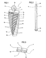
Figure 1 , thenumeral 1 denotes an ornamental object made in accordance with this invention. - In the example illustrated the
object 1 is a jewel to which explicit reference is made herein without in any way limiting the scope of the invention, since the structure and the kit described below could be suitable for making ornaments, promotional giveaways, jewellery, key rings and other items. Thejewel 1 comprises arod 2 and a plurality ofblocks 3 fitted on therod 2. - The
rod 2 has a main axis A and is twisted about the axis A. - In other words, during its production, the
rod 2 was subjected to a twisting moment applied at the twoends - As illustrated in particular in
Figure 2 , a section of therod 2, preferably at anupper end 2a of therod 2, is therefore rotated relative to a cross-section of therod 2 at itslower end 2b. As illustrated, the end sections are kept substantially parallel. - Advantageously, the relative rotation of the two end sections is an angle of between 20 and 360 sexagesimal degrees.
- The
blocks 3 are positioned according to the profile of the rod, that it so say, their orientation in space follows the curvature of therod 2. - In particular with reference to
Figure 3 , looking in more detail at theblocks 3, it is clear that theblocks 3 have ahole 4 made in them, through which therod 2 is passed when assembling thejewel 1. - The
hole 4 is preferably shaped to match the cross-section of therod 2 in such a way that, once fitted from theend 2a and moved towards theend 2b, it can follow the profile of the rod. Appropriately, the dimensions of the cross-section of theholes 4 are greater than the dimensions of the cross-section of therod 2, allowing theblocks 3 to slide along therod 2, following the profile of the rod. - A preferred tolerance value for the
holes 4 relative to therod 2 is ±0.3 mm, allowing said sliding. - Each
block 3, preferably a parallelepiped, has afront face 5, divided into afirst portion 5a and asecond portion 5b, afirst face 6 and asecond face 7. - The first and second portions preferably have the same size and shape.
- More particularly, with reference to
Figures 1 and4 , thejewel 1 comprises a first type ofblock 3a and a second type ofblock 3b. - Each block has its
front face 5 divided into the first andsecond portions - The first and
second portions blocks 3a are respectively decorated with afirst pattern 8 and with asecond pattern 9. - The first and
second portions blocks 3b are respectively decorated with athird pattern 10 and with afourth pattern 11. - As illustrated, the arrangement of the
blocks 3 on thetwisted rod 2 and the correspondingsuperposed patterns - The preferred angular range gives the object 1 a precise resemblance to DNA helixes.
- It should be noticed that the parallelepiped shape of the
blocks 3 allows them to be fitted on therod 2 in two ways, that is to say, with thefirst face 6 facing theupper end 2a of therod 2 or facing itslower end 2b, so that for eachblock 3, it is possible to invert the position of the twoportions corresponding patterns - With reference to
Figure 2 , at itslower end 2b therod 2 has aplate 12 against which theblocks 3 fitted on therod 2 stop. In an alternative embodiment, not illustrated, theplate 12 is substituted by a deformation of theend 2b which prevents theblocks 3 from sliding beyond theend 2b. - Alternatively, in another embodiment which is not illustrated, the
end 2b is threaded in such a way as to receive and engage with a nut which stops theblocks 3. - Said configuration also allows the fitting of another ornamental component from the
end 2b. - The
plate 12 or the deformation or the nut therefore forms stop means for the blocks at thelower end 2b of therod 2. - In particular with reference to
Figure 6 , it should be noticed that therod 2 has a throughhole 13 made in theupper end 2a. - A locking or fastening
element 14, for example a ring, engages in thehole 13 and prevents theblocks 3 from coming off therod 2, therefore forming stop means for theblocks 3 at theend 2a of therod 2. - The construction kit for making an
ornamental object 1 such as that described above therefore comprises therod 2, a plurality ofblocks 3, preferably both of the first type and of the second type, and alocking element 14, both thehole 13 and the first stop means 12 already being made in therod 2. - In the preferred embodiment, the kit comprises a number of
blocks 3 of the first type equal to the maximum number ofblocks 3 which can be fitted on therod 2 and a number ofblocks 3 of the second type which is also equal to the maximum number ofblocks 3 which can be fitted on therod 2. - In that way, since as indicated the
individual blocks 3 can be turned over, the kit comprises all of theblocks 3 necessary for recreating any DNA. It should be noticed that in DNA the combinations of elements in the two helixes are unique and therefore two types of blocks with a total of four patterns arranged in pairs are sufficient. -
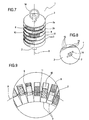
Figure 7 shows a second embodiment of theornamental object 1 in which theblocks 3 substantially have the shape of a disk. - The
blocks 3 are preferably substantially cylindrical. - In alternative embodiments not illustrated, the
blocks 3 are substantially spherical in shape. - In that way, if the
ornamental object 1, once put on, is in contact with the body of a generic wearer, not illustrated, the outer surface of theobject 1 does not have sharp edges which could be uncomfortable. - In other words, preferably, to improve the wearability of the
ornamental object 1, theblocks 3 have a substantially curvilinear outer profile. For example, the case where theornamental object 1 is a bracelet worn on a person's wrist is imaginable. - Advantageously, the
blocks 3 each have thehole 4 made in them and thepatterns block 3. - The
patterns - As shown in
Figure 8 , in a third embodiment, theblocks 3 are substantially in the shape of a disk and comprise abevel 15. - The
patterns bevel 15 in such a way as to obtain substantially the same aesthetic and customised effect as described above. - Advantageously, even the
bevelled blocks 3 have thehole 4 made in them which allows them to be fitted on thetwisted rod 2. - As shown in
Figure 9 , in a fourth embodiment of theornamental object 1 the axis A of therod 2 is curved. - Similarly to what is described above, in this embodiment too the
blocks 3 are fitted along therod 2 and follow its profile. - That optimises the possibility of wearing the
object 1, for example if the object is a bracelet. According to this invention, a method for making a substantially uniqueornamental object 1 using the kit described above comprises the steps of defining a unique sequence ofblocks 3 and fitting theblocks 3 on therod 2. - Since the sequence proposed by the superposed
patterns patterns - It should be noticed that the
patterns corresponding block 3, in particular in theportions - Alternatively, the
patterns - According to this assembly method, the step of defining a unique sequence for superposing the
blocks 3 comprises the step of defining a DNA sequence to be recreated using thepatterns - Advantageously, the
patterns - For example, the
first pattern 8 is linked to adenine, thesecond pattern 9 is linked to thymine, thethird pattern 10 is linked to cytosine and thepattern 11 is linked to guanine, since it is known that in DNA the links between the nitrogenous bases are always and only of the adenine - thymine and cytosine - guanine type. - Preferably, the step of defining a unique sequence is performed starting with a set of personal information relating to the generic user which, when suitably processed in a way not described here because it is not part of this invention, provides the DNA sequence for the user, which is then recreated by superposing the
blocks 3. - For example, the personal information that contributes to the formation of the sequence comprises eye colour, nose shape, hair colour, skin colour and other information.
- The invention described brings important advantages.
- The construction kit described allows the production of highly customised ornamental objects such as the
jewel 1. - Such objects have a low cost thanks to their simplicity.
- The definition of the superposing layouts based on the DNA of the user offers the possibility of an extremely unique model, since in general the DNA of every person is different.
- Advantageously, a kit seller can be asked to make the object, or it can be made by the end user.
Claims (16)
- A construction kit for making an ornamental object comprising a rod (2) having a main axis (A), a plurality of blocks (3) each having a hole (4) made in it, the kit also comprising stop means (12) for the blocks (3) which can be associated with a first end (2b) of the rod (2), second stop means (13, 14) for the blocks (3) which can with associated with a second end (2a) of the rod, the kit being characterised in that the rod (2) is twisted about the main axis (A) and the holes (4) are shaped in such a way that the corresponding block (3) can be fitted along the rod (2) in such a way as to follow the profile of the rod (2).
- The construction kit for making an ornamental object according to claim 1, characterised in that the holes (4) are substantially shaped to match the cross-section of the rod (2).
- The construction kit for making an ornamental object according to claim 1 or 2, characterised in that it comprises a first type of blocks (3a) each having a front face (5) divided into a first portion and a second portion (5a, 5b), the first and second portions (5a, 5b) respectively being decorated with a first and a second pattern (8, 9).
- The construction kit for making an ornamental object according to any of the foregoing claims, characterised in that it comprises a second type of blocks (3b) each having a front face (5) divided into a first portion and a second portion (5a, 5b), the first and second portions (5a, 5b) respectively being decorated with a third and a fourth pattern (10, 11).
- The construction kit for making an ornamental object according to claims 3 and 4, characterised in that it comprises a number of blocks (3a) of the first type and a number of blocks (3b) of the second type which are both equal to the maximum number of blocks (3) that can be fitted on the rod (2).
- The construction kit for making an ornamental object according to any of the foregoing claims, characterised in that a section of the rod (2) at the first end (2b) is rotated relative to a cross-section of the rod (2) at the second end (2a) by an angle of between 20° and 360°.
- The construction kit for making an ornamental object according to any of the foregoing claims, characterised in that the first stop means (12) are formed by a deformation of the first end (2b) of the rod (2).
- The construction kit for making an ornamental object according to any of the foregoing claims, characterised in that the second stop means (13, 14) comprise a through hole (13) made in the second end (2a) of the rod (2) and a locking element (14) which can engage in the through hole.
- The construction kit for making an ornamental object according to any of the foregoing claims, characterised in that the blocks (3) have a curvilinear profile, in particular, they are substantially in the shape of a disk or cylinder or sphere.
- The construction kit for making an ornamental object according to claim 9, characterised in that the blocks (3) have at least one pattern (8, 9, 10, 11) on their outer surface.
- The construction kit for making an ornamental object according to claim 9 or 10, characterised in that the blocks (3) substantially in the shape of a disk comprise a bevel (15), the pattern (8, 9, 10, 11) preferably being made on the bevel (15).
- The construction kit for making an ornamental object according to any of the foregoing claims, characterised in that the axis (A) is curved.
- An ornamental object using a construction kit according to any one of preceeding claims wherein the blocks (3) are fitted along the rod (2), the stop means (12) for the blocks (3) are associated at a first end (2b) of the rod (2), the second stop means (13, 14) for the blocks are associated at a second end (2a) of the rod (2), the ornamental object being characterised in that and the blocks (3) are positioned according to the profile of the rod (2).
- The ornamental object according to claim 13, characterised in that the blocks (3) are fitted along the rod (2) in such a way that superposing the first, second, third and fourth patterns (8, 9, 10, 11) of superposed blocks (3) represents the double helix structure of DNA.
- A method for making an ornamental object using a construction kit according to any of the claims from 1 to 12, the method being characterised in that it comprises the steps of:defining a unique sequence of blocks (3);fitting the blocks (3) on the rod (2) in such a way that they reproduce said sequence;preventing the blocks (3) from sliding on the rod (2).
- The method according to claim 15, characterised in that the step of defining a unique sequence comprises the step of defining a DNA sequence to be recreated using the blocks (3).
Applications Claiming Priority (1)
| Application Number | Priority Date | Filing Date | Title |
|---|---|---|---|
| ITBO2009A000488A IT1395022B1 (en) | 2009-07-24 | 2009-07-24 | CONSTRUCTION KIT. |
Publications (2)
| Publication Number | Publication Date |
|---|---|
| EP2277405A1 EP2277405A1 (en) | 2011-01-26 |
| EP2277405B1 true EP2277405B1 (en) | 2012-09-19 |
Family
ID=41800725
Family Applications (1)
| Application Number | Title | Priority Date | Filing Date |
|---|---|---|---|
| EP20100169794 Not-in-force EP2277405B1 (en) | 2009-07-24 | 2010-07-16 | A construction kit. |
Country Status (2)
| Country | Link |
|---|---|
| EP (1) | EP2277405B1 (en) |
| IT (1) | IT1395022B1 (en) |
Families Citing this family (1)
| Publication number | Priority date | Publication date | Assignee | Title |
|---|---|---|---|---|
| DE102010034004B4 (en) * | 2010-08-11 | 2014-11-20 | Christian Rogg | Jewelery stones holding |
Family Cites Families (4)
| Publication number | Priority date | Publication date | Assignee | Title |
|---|---|---|---|---|
| FR2344245A1 (en) * | 1976-03-18 | 1977-10-14 | Gay Xavier | Jewellery piece with movable precious stones - has pendant with stone set in and movable along surface groove with V-section side walls |
| US20020055118A1 (en) * | 1998-06-24 | 2002-05-09 | Yong-Bin Eym | Method of preparing objects containing DNA |
| JP2003041537A (en) * | 2001-07-31 | 2003-02-13 | Yagikuma:Kk | Structural body for joint type cushion block |
| JP3111240U (en) * | 2005-03-14 | 2005-07-14 | 敏貴 並木 | tie |
-
2009
- 2009-07-24 IT ITBO2009A000488A patent/IT1395022B1/en active
-
2010
- 2010-07-16 EP EP20100169794 patent/EP2277405B1/en not_active Not-in-force
Also Published As
| Publication number | Publication date |
|---|---|
| ITBO20090488A1 (en) | 2011-01-25 |
| IT1395022B1 (en) | 2012-09-05 |
| EP2277405A1 (en) | 2011-01-26 |
Similar Documents
| Publication | Publication Date | Title |
|---|---|---|
| US20080209943A1 (en) | Setting for gemstones, particularly diamonds | |
| US20100300146A1 (en) | Removable bracelet charm | |
| CN100518571C (en) | Precious stones with invisible mosaic structure | |
| EP2277405B1 (en) | A construction kit. | |
| CN210492921U (en) | Chain bead embedded composite jade bracelet | |
| KR102359670B1 (en) | A multi-hollow decoration manufacturing method that can set up a three-dimensional volume increase structure and a multi-expression structure | |
| US20050193769A1 (en) | Ring | |
| EP3051971B1 (en) | Modular element for jewellery or costume jewellery articles | |
| Pichaničová et al. | Precious Stones in Religious Objects. Use and Representation in the Early Medieval Latin West | |
| CN207949120U (en) | A kind of jewellery being convenient for changing decoration | |
| CN209750025U (en) | Rotatable ornament capable of realizing multiple wearing modes through magnetic combination | |
| CN207590179U (en) | A kind of diamond rabbet structure | |
| CN205492831U (en) | Ornament | |
| CN202425731U (en) | Bracelet | |
| CN216220462U (en) | Embedded jewelry | |
| KR200393782Y1 (en) | decoration jewel of ceramic material | |
| CN217117685U (en) | Pendant with embedded rotating structure | |
| CN218044074U (en) | Improved elastic bead chain | |
| CN210809578U (en) | Necklace pendant capable of being used as finger ring head or ear stud head | |
| CN211021270U (en) | Hand string | |
| CN206852195U (en) | A kind of jewellery | |
| CN205696119U (en) | A kind of bracelet movable decoration fastener | |
| CN2787039Y (en) | Coloured glaze ornament | |
| CN210184728U (en) | Wear comfortable heart-shaped ring | |
| CN212661281U (en) | Jewelry capable of being disassembled and assembled |
Legal Events
| Date | Code | Title | Description |
|---|---|---|---|
| PUAI | Public reference made under article 153(3) epc to a published international application that has entered the european phase |
Free format text: ORIGINAL CODE: 0009012 |
|
| AK | Designated contracting states |
Kind code of ref document: A1 Designated state(s): AL AT BE BG CH CY CZ DE DK EE ES FI FR GB GR HR HU IE IS IT LI LT LU LV MC MK MT NL NO PL PT RO SE SI SK SM TR |
|
| AX | Request for extension of the european patent |
Extension state: BA ME RS |
|
| 17P | Request for examination filed |
Effective date: 20110715 |
|
| GRAP | Despatch of communication of intention to grant a patent |
Free format text: ORIGINAL CODE: EPIDOSNIGR1 |
|
| GRAS | Grant fee paid |
Free format text: ORIGINAL CODE: EPIDOSNIGR3 |
|
| GRAA | (expected) grant |
Free format text: ORIGINAL CODE: 0009210 |
|
| RAP1 | Party data changed (applicant data changed or rights of an application transferred) |
Owner name: THESIS S.R.L. |
|
| AK | Designated contracting states |
Kind code of ref document: B1 Designated state(s): AL AT BE BG CH CY CZ DE DK EE ES FI FR GB GR HR HU IE IS IT LI LT LU LV MC MK MT NL NO PL PT RO SE SI SK SM TR |
|
| REG | Reference to a national code |
Ref country code: GB Ref legal event code: FG4D |
|
| REG | Reference to a national code |
Ref country code: CH Ref legal event code: EP |
|
| REG | Reference to a national code |
Ref country code: IE Ref legal event code: FG4D |
|
| REG | Reference to a national code |
Ref country code: AT Ref legal event code: REF Ref document number: 575558 Country of ref document: AT Kind code of ref document: T Effective date: 20121015 |
|
| REG | Reference to a national code |
Ref country code: DE Ref legal event code: R096 Ref document number: 602010002857 Country of ref document: DE Effective date: 20121115 |
|
| PG25 | Lapsed in a contracting state [announced via postgrant information from national office to epo] |
Ref country code: FI Free format text: LAPSE BECAUSE OF FAILURE TO SUBMIT A TRANSLATION OF THE DESCRIPTION OR TO PAY THE FEE WITHIN THE PRESCRIBED TIME-LIMIT Effective date: 20120919 Ref country code: LT Free format text: LAPSE BECAUSE OF FAILURE TO SUBMIT A TRANSLATION OF THE DESCRIPTION OR TO PAY THE FEE WITHIN THE PRESCRIBED TIME-LIMIT Effective date: 20120919 Ref country code: NO Free format text: LAPSE BECAUSE OF FAILURE TO SUBMIT A TRANSLATION OF THE DESCRIPTION OR TO PAY THE FEE WITHIN THE PRESCRIBED TIME-LIMIT Effective date: 20121219 Ref country code: HR Free format text: LAPSE BECAUSE OF FAILURE TO SUBMIT A TRANSLATION OF THE DESCRIPTION OR TO PAY THE FEE WITHIN THE PRESCRIBED TIME-LIMIT Effective date: 20120919 |
|
| REG | Reference to a national code |
Ref country code: NL Ref legal event code: VDEP Effective date: 20120919 |
|
| REG | Reference to a national code |
Ref country code: AT Ref legal event code: MK05 Ref document number: 575558 Country of ref document: AT Kind code of ref document: T Effective date: 20120919 |
|
| REG | Reference to a national code |
Ref country code: LT Ref legal event code: MG4D Effective date: 20120919 |
|
| PG25 | Lapsed in a contracting state [announced via postgrant information from national office to epo] |
Ref country code: GR Free format text: LAPSE BECAUSE OF FAILURE TO SUBMIT A TRANSLATION OF THE DESCRIPTION OR TO PAY THE FEE WITHIN THE PRESCRIBED TIME-LIMIT Effective date: 20121220 Ref country code: SI Free format text: LAPSE BECAUSE OF FAILURE TO SUBMIT A TRANSLATION OF THE DESCRIPTION OR TO PAY THE FEE WITHIN THE PRESCRIBED TIME-LIMIT Effective date: 20120919 Ref country code: LV Free format text: LAPSE BECAUSE OF FAILURE TO SUBMIT A TRANSLATION OF THE DESCRIPTION OR TO PAY THE FEE WITHIN THE PRESCRIBED TIME-LIMIT Effective date: 20120919 Ref country code: SE Free format text: LAPSE BECAUSE OF FAILURE TO SUBMIT A TRANSLATION OF THE DESCRIPTION OR TO PAY THE FEE WITHIN THE PRESCRIBED TIME-LIMIT Effective date: 20120919 |
|
| PG25 | Lapsed in a contracting state [announced via postgrant information from national office to epo] |
Ref country code: RO Free format text: LAPSE BECAUSE OF FAILURE TO SUBMIT A TRANSLATION OF THE DESCRIPTION OR TO PAY THE FEE WITHIN THE PRESCRIBED TIME-LIMIT Effective date: 20120919 Ref country code: IS Free format text: LAPSE BECAUSE OF FAILURE TO SUBMIT A TRANSLATION OF THE DESCRIPTION OR TO PAY THE FEE WITHIN THE PRESCRIBED TIME-LIMIT Effective date: 20130119 Ref country code: EE Free format text: LAPSE BECAUSE OF FAILURE TO SUBMIT A TRANSLATION OF THE DESCRIPTION OR TO PAY THE FEE WITHIN THE PRESCRIBED TIME-LIMIT Effective date: 20120919 Ref country code: NL Free format text: LAPSE BECAUSE OF FAILURE TO SUBMIT A TRANSLATION OF THE DESCRIPTION OR TO PAY THE FEE WITHIN THE PRESCRIBED TIME-LIMIT Effective date: 20120919 Ref country code: ES Free format text: LAPSE BECAUSE OF FAILURE TO SUBMIT A TRANSLATION OF THE DESCRIPTION OR TO PAY THE FEE WITHIN THE PRESCRIBED TIME-LIMIT Effective date: 20121230 Ref country code: BE Free format text: LAPSE BECAUSE OF FAILURE TO SUBMIT A TRANSLATION OF THE DESCRIPTION OR TO PAY THE FEE WITHIN THE PRESCRIBED TIME-LIMIT Effective date: 20120919 Ref country code: CZ Free format text: LAPSE BECAUSE OF FAILURE TO SUBMIT A TRANSLATION OF THE DESCRIPTION OR TO PAY THE FEE WITHIN THE PRESCRIBED TIME-LIMIT Effective date: 20120919 |
|
| PG25 | Lapsed in a contracting state [announced via postgrant information from national office to epo] |
Ref country code: PT Free format text: LAPSE BECAUSE OF FAILURE TO SUBMIT A TRANSLATION OF THE DESCRIPTION OR TO PAY THE FEE WITHIN THE PRESCRIBED TIME-LIMIT Effective date: 20130121 Ref country code: PL Free format text: LAPSE BECAUSE OF FAILURE TO SUBMIT A TRANSLATION OF THE DESCRIPTION OR TO PAY THE FEE WITHIN THE PRESCRIBED TIME-LIMIT Effective date: 20120919 Ref country code: SK Free format text: LAPSE BECAUSE OF FAILURE TO SUBMIT A TRANSLATION OF THE DESCRIPTION OR TO PAY THE FEE WITHIN THE PRESCRIBED TIME-LIMIT Effective date: 20120919 |
|
| PG25 | Lapsed in a contracting state [announced via postgrant information from national office to epo] |
Ref country code: AT Free format text: LAPSE BECAUSE OF FAILURE TO SUBMIT A TRANSLATION OF THE DESCRIPTION OR TO PAY THE FEE WITHIN THE PRESCRIBED TIME-LIMIT Effective date: 20120919 |
|
| PLBE | No opposition filed within time limit |
Free format text: ORIGINAL CODE: 0009261 |
|
| STAA | Information on the status of an ep patent application or granted ep patent |
Free format text: STATUS: NO OPPOSITION FILED WITHIN TIME LIMIT |
|
| PG25 | Lapsed in a contracting state [announced via postgrant information from national office to epo] |
Ref country code: DK Free format text: LAPSE BECAUSE OF FAILURE TO SUBMIT A TRANSLATION OF THE DESCRIPTION OR TO PAY THE FEE WITHIN THE PRESCRIBED TIME-LIMIT Effective date: 20120919 Ref country code: BG Free format text: LAPSE BECAUSE OF FAILURE TO SUBMIT A TRANSLATION OF THE DESCRIPTION OR TO PAY THE FEE WITHIN THE PRESCRIBED TIME-LIMIT Effective date: 20121219 |
|
| 26N | No opposition filed |
Effective date: 20130620 |
|
| REG | Reference to a national code |
Ref country code: DE Ref legal event code: R097 Ref document number: 602010002857 Country of ref document: DE Effective date: 20130620 |
|
| PG25 | Lapsed in a contracting state [announced via postgrant information from national office to epo] |
Ref country code: CY Free format text: LAPSE BECAUSE OF FAILURE TO SUBMIT A TRANSLATION OF THE DESCRIPTION OR TO PAY THE FEE WITHIN THE PRESCRIBED TIME-LIMIT Effective date: 20120919 |
|
| PG25 | Lapsed in a contracting state [announced via postgrant information from national office to epo] |
Ref country code: MC Free format text: LAPSE BECAUSE OF FAILURE TO SUBMIT A TRANSLATION OF THE DESCRIPTION OR TO PAY THE FEE WITHIN THE PRESCRIBED TIME-LIMIT Effective date: 20120919 |
|
| REG | Reference to a national code |
Ref country code: IE Ref legal event code: MM4A |
|
| PG25 | Lapsed in a contracting state [announced via postgrant information from national office to epo] |
Ref country code: IE Free format text: LAPSE BECAUSE OF NON-PAYMENT OF DUE FEES Effective date: 20130716 |
|
| PGFP | Annual fee paid to national office [announced via postgrant information from national office to epo] |
Ref country code: FR Payment date: 20140731 Year of fee payment: 5 Ref country code: GB Payment date: 20140729 Year of fee payment: 5 |
|
| PGFP | Annual fee paid to national office [announced via postgrant information from national office to epo] |
Ref country code: IT Payment date: 20140729 Year of fee payment: 5 |
|
| PGFP | Annual fee paid to national office [announced via postgrant information from national office to epo] |
Ref country code: DE Payment date: 20140930 Year of fee payment: 5 |
|
| REG | Reference to a national code |
Ref country code: CH Ref legal event code: PL |
|
| PG25 | Lapsed in a contracting state [announced via postgrant information from national office to epo] |
Ref country code: CH Free format text: LAPSE BECAUSE OF NON-PAYMENT OF DUE FEES Effective date: 20140731 Ref country code: LI Free format text: LAPSE BECAUSE OF NON-PAYMENT OF DUE FEES Effective date: 20140731 |
|
| PG25 | Lapsed in a contracting state [announced via postgrant information from national office to epo] |
Ref country code: SM Free format text: LAPSE BECAUSE OF FAILURE TO SUBMIT A TRANSLATION OF THE DESCRIPTION OR TO PAY THE FEE WITHIN THE PRESCRIBED TIME-LIMIT Effective date: 20120919 |
|
| PG25 | Lapsed in a contracting state [announced via postgrant information from national office to epo] |
Ref country code: MT Free format text: LAPSE BECAUSE OF FAILURE TO SUBMIT A TRANSLATION OF THE DESCRIPTION OR TO PAY THE FEE WITHIN THE PRESCRIBED TIME-LIMIT Effective date: 20120919 Ref country code: TR Free format text: LAPSE BECAUSE OF FAILURE TO SUBMIT A TRANSLATION OF THE DESCRIPTION OR TO PAY THE FEE WITHIN THE PRESCRIBED TIME-LIMIT Effective date: 20120919 |
|
| PG25 | Lapsed in a contracting state [announced via postgrant information from national office to epo] |
Ref country code: LU Free format text: LAPSE BECAUSE OF NON-PAYMENT OF DUE FEES Effective date: 20130716 Ref country code: HU Free format text: LAPSE BECAUSE OF FAILURE TO SUBMIT A TRANSLATION OF THE DESCRIPTION OR TO PAY THE FEE WITHIN THE PRESCRIBED TIME-LIMIT; INVALID AB INITIO Effective date: 20100716 Ref country code: MK Free format text: LAPSE BECAUSE OF FAILURE TO SUBMIT A TRANSLATION OF THE DESCRIPTION OR TO PAY THE FEE WITHIN THE PRESCRIBED TIME-LIMIT Effective date: 20120919 |
|
| REG | Reference to a national code |
Ref country code: DE Ref legal event code: R119 Ref document number: 602010002857 Country of ref document: DE |
|
| GBPC | Gb: european patent ceased through non-payment of renewal fee |
Effective date: 20150716 |
|
| PG25 | Lapsed in a contracting state [announced via postgrant information from national office to epo] |
Ref country code: IT Free format text: LAPSE BECAUSE OF NON-PAYMENT OF DUE FEES Effective date: 20150716 Ref country code: GB Free format text: LAPSE BECAUSE OF NON-PAYMENT OF DUE FEES Effective date: 20150716 Ref country code: DE Free format text: LAPSE BECAUSE OF NON-PAYMENT OF DUE FEES Effective date: 20160202 |
|
| REG | Reference to a national code |
Ref country code: FR Ref legal event code: ST Effective date: 20160331 |
|
| PG25 | Lapsed in a contracting state [announced via postgrant information from national office to epo] |
Ref country code: FR Free format text: LAPSE BECAUSE OF NON-PAYMENT OF DUE FEES Effective date: 20150731 |
|
| PG25 | Lapsed in a contracting state [announced via postgrant information from national office to epo] |
Ref country code: AL Free format text: LAPSE BECAUSE OF FAILURE TO SUBMIT A TRANSLATION OF THE DESCRIPTION OR TO PAY THE FEE WITHIN THE PRESCRIBED TIME-LIMIT Effective date: 20120919 |